EP4231073A1 - Optical fiber ribbon - Google Patents
Optical fiber ribbon Download PDFInfo
- Publication number
- EP4231073A1 EP4231073A1 EP21882736.8A EP21882736A EP4231073A1 EP 4231073 A1 EP4231073 A1 EP 4231073A1 EP 21882736 A EP21882736 A EP 21882736A EP 4231073 A1 EP4231073 A1 EP 4231073A1
- Authority
- EP
- European Patent Office
- Prior art keywords
- optical fiber
- optical fibers
- coating layer
- collective coating
- thickness
- Prior art date
- Legal status (The legal status is an assumption and is not a legal conclusion. Google has not performed a legal analysis and makes no representation as to the accuracy of the status listed.)
- Granted
Links
Images

Classifications
-
- G—PHYSICS
- G02—OPTICS
- G02B—OPTICAL ELEMENTS, SYSTEMS OR APPARATUS
- G02B6/00—Light guides; Structural details of arrangements comprising light guides and other optical elements, e.g. couplings
- G02B6/44—Mechanical structures for providing tensile strength and external protection for fibres, e.g. optical transmission cables
- G02B6/4401—Optical cables
- G02B6/4429—Means specially adapted for strengthening or protecting the cables
- G02B6/443—Protective covering
- G02B6/4431—Protective covering with provision in the protective covering, e.g. weak line, for gaining access to one or more fibres, e.g. for branching or tapping
-
- G—PHYSICS
- G02—OPTICS
- G02B—OPTICAL ELEMENTS, SYSTEMS OR APPARATUS
- G02B6/00—Light guides; Structural details of arrangements comprising light guides and other optical elements, e.g. couplings
- G02B6/44—Mechanical structures for providing tensile strength and external protection for fibres, e.g. optical transmission cables
- G02B6/4401—Optical cables
- G02B6/4403—Optical cables with ribbon structure
-
- G—PHYSICS
- G02—OPTICS
- G02B—OPTICAL ELEMENTS, SYSTEMS OR APPARATUS
- G02B6/00—Light guides; Structural details of arrangements comprising light guides and other optical elements, e.g. couplings
- G02B6/44—Mechanical structures for providing tensile strength and external protection for fibres, e.g. optical transmission cables
- G02B6/4401—Optical cables
- G02B6/4403—Optical cables with ribbon structure
- G02B6/4404—Multi-podded
-
- G—PHYSICS
- G02—OPTICS
- G02B—OPTICAL ELEMENTS, SYSTEMS OR APPARATUS
- G02B6/00—Light guides; Structural details of arrangements comprising light guides and other optical elements, e.g. couplings
- G02B6/44—Mechanical structures for providing tensile strength and external protection for fibres, e.g. optical transmission cables
- G02B6/4479—Manufacturing methods of optical cables
- G02B6/448—Ribbon cables
Definitions
- the present disclosure relates to an optical fiber ribbon.
- the present application claims priority from Japanese Patent Application No. 2020-175367 filed on October 19, 2020 , contents of which are incorporated by reference in its entirety.
- An optical fiber ribbon according to the present disclosure includes:
- the optical fiber ribbons are mounted in the optical fiber cable at high density, since the optical fiber ribbons tend to be in contact with each other, friction may occur between the optical fiber ribbons. When the friction occurs non-uniformly in a longitudinal direction of the cable, the cable tends to meander. Further, transmission characteristics of the cable at a low temperature tend to deteriorate. In particular, in a case in which outer diameters of a plurality of optical fibers are different, the cable is more likely to meander, and the transmission characteristics are more likely to deteriorate.
- the present disclosure provides an optical fiber ribbon that enables high-density mounting of optical fibers in an optical fiber cable and prevents occurrence of cable meandering.
- the collective coating layer includes the thick portion and at least two thin portions, and the thickness of the collective coating layer is non-uniform.
- the difference between the thickness of the collective coating layer in the thick portion and the thickness of the collective coating layer in the thin portion is as relatively large as 5 ⁇ m or more and 19 ⁇ m or less, a contact area between the optical fiber ribbons can be reduced. Therefore, friction is unlikely to occur between the optical fiber ribbons adj acent to each other, and even when the optical fiber ribbons are mounted in a cable at high density, cable meandering can be further prevented.
- the optical fiber ribbons can be mounted in the cable at high density.
- a distance between centers of the optical fibers adjacent to each other may be 220 ⁇ m or more and 280 ⁇ m or less.
- the distance between the centers of the optical fibers adjacent to each other is 220 ⁇ m or more and 280 ⁇ m or less, a general splicing device can be used. Even if each of the optical fibers is small in diameter, it is not necessary to prepare a dedicated splicing device for small-diameter optical fibers, so that a versatile optical fiber ribbon can be provided.
- the collective coating layer may include a non-connected portion at which the optical fibers adj acent to each other are not connected in at least a part of the plurality of optical fibers.
- the connected portion may be formed intermittently in the longitudinal direction.
- the optical fiber ribbon is easily deformed in a cross section perpendicular to the longitudinal direction. Accordingly, the optical fibers can be mounted in the optical fiber cable at high density.
- the plurality of optical fibers may include a first optical fiber having a first outer diameter and a second optical fiber having a second outer diameter.
- the optical fibers since the plurality of optical fiber ribbons include the first optical fiber having the first outer diameter and the second optical fiber having the second outer diameter, the optical fibers can be mounted in the optical fiber cable at high density while preventing the cable meandering.
- an optical fiber ribbon that enables high-density mounting of optical fibers in an optical fiber cable and prevents occurrence of cable meandering can be provided.
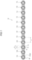
- FIG. 1 is a cross-sectional view perpendicular to a longitudinal direction of an optical fiber ribbon 1A according to an embodiment of the present disclosure.
- the optical fiber ribbon 1A includes a plurality of optical fibers 11 and a collective coating layer 20 that covers the plurality of optical fibers 11.
- 12 optical fibers 11A to 11L are arranged in parallel in a direction orthogonal to the longitudinal direction of the optical fiber ribbon 1A.
- the plurality of optical fibers 11 are arranged at regular intervals. Outer peripheries of the plurality of optical fibers 11 are covered with the collective coating layer 20, and the entire optical fibers 11 are connected by the collective coating layer 20.
- Each optical fiber 11 includes, for example, a glass fiber 12 including a core and a cladding, a primary resin layer 13 covering an outer periphery of the glass fiber 12, and a secondary resin layer 14 covering an outer periphery of the primary resin layer 13.
- the glass fiber 12 may include pure silica glass, silica glass doped with germanium, or silica glass doped with fluorine.
- the primary resin layer 13 may include a soft material having a relatively low Young's modulus, as a buffer layer.
- the secondary resin layer 14 may include a hard material having a relatively high Young's modulus, as a protective layer.
- the Young's modulus of the primary resin layer 13 at 23°C is preferably 0.04 MPa or more and 0.8 MPa or less, more preferably 0.05 MPa or more and 0.7 MPa or less, and still more preferably 0.05 MPa or more and 0.6 MPa or less. Since the Young's modulus of the primary resin layer 13 is 0.04 MPa or more and 0.8 MPa or less, voids are less likely to be generated in the optical fiber.
- the Young's modulus of the secondary resin layer 14 at 23°C is preferably 900 MPa or more, more preferably 1000 MPa or more, and still more preferably 1200 MPa or more.
- the Young's modulus of the secondary resin layer 14 at 23°C may be 3000 MPa or less, 2500 MPa or less, 2000 MPa or less, or 1800 MPa or less. Since the Young's modulus of the secondary resin layer 14 is 900 MPa or more, lateral pressure resistance is likely to be improved. When the Young's modulus of the secondary resin layer 14 is 3000 MPa or less, since the secondary resin layer 14 has appropriate elongation at break, stripping is easily performed.
- the collective coating layer 20 includes connected portions 21 at each of which adjacent optical fibers are connected in at least a part of the plurality of optical fibers 11.
- the connected portions 21 are disposed between all adjacent optical fibers.
- the connected portions 21 are disposed such that a distance P between centers of adjacent optical fibers is 220 ⁇ m or more and 280 ⁇ m or less.
- the collective coating layer 20 may contain, for example, an ultraviolet curable resin.
- a Young's modulus of the collective coating layer 20 at 23°C is preferably 50 MPa or more and 900 MPa or less, and more preferably 100 MPa or more and 800 MPa or less, from the viewpoint of lateral pressure resistance and flexibility of the optical fiber ribbon.
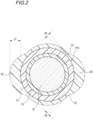
- FIG. 2 is a cross-sectional view of one optical fiber 11B among the plurality of optical fibers 11 in the optical fiber ribbon 1A shown in FIG. 1 . Since configurations of other optical fibers 11A and 11C to 11L are the same as the configuration of the optical fiber 11B shown in FIG. 2 , repeated description will be omitted.
- the collective coating layer 20 includes a thick portion 22 and at least two thin portions 23.
- a thickness of the collective coating layer 20 is non-uniform on the outer periphery of the optical fiber 11B.
- the thickness of the collective coating layer 20 on the outer periphery of the optical fiber 11B is measured at a total of five locations except for the connected portion 21. Among the five locations, a portion around a location where the thickness of the collective coating layer 20 is largest is defined as the thick portion 22, and a portion around a location where the thickness of the collective coating layer 20 is thinner than the thick portion 22 by 5 ⁇ m or more is defined as the thin portion 23.
- Positions of the thick portion 22 and the thin portion 23 on the outer periphery of the optical fiber 11B shown in FIG. 2 are merely examples, and the present disclosure is not limited thereto. Further, since the collective coating layer 20 covers the outer periphery of the optical fiber 11B, there is no location where the optical fiber 11B is exposed from the collective coating layer 20.
- a thickness d2 of the collective coating layer 20 in the thin portion 23 is smaller than a thickness d1 of the collective coating layer 20 in the thick portion 22. Specifically, a difference between the thickness d1 of the collective coating layer 20 in the thick portion 22 and the thickness d2 of the collective coating layer 20 in the thin portion 23 is 5 ⁇ m or more and 19 ⁇ m or less.
- the thickness d1 of the collective coating layer 20 in the thick portion 22 is, for example, 20 ⁇ m or less.
- the thickness d2 of the collective coating layer 20 in the thin portion 23 is, for example, 1 ⁇ m or more and 15 ⁇ m or less.
- the thickness of the collective coating layer between the optical fiber 11B and the optical fiber 11A or 11C refers to a thickness excluding the connected portion 21.
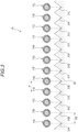
- FIG. 3 is a schematic view showing a relationship between a pitch of the optical fiber ribbon 1A (distance P between the centers of the adjacent optical fibers) and a V-groove base 30 of the fusion machine.
- the fusion splicer includes the V-groove base 30 including a plurality of V-grooves 31 in which the plurality of optical fibers 11 are arranged.
- the 12 optical fibers 11A to 11L are respectively arranged in 12 V-grooves 31A to 31L.
- a pitch P0 of the V-grooves 31A to 31L is 250 ⁇ m according to an international standard of an outer diameter of the optical fiber.
- the optical fibers 11A to 11L in a state in which the collective coating layer 20 is stripped are arranged above the V-groove base 30.
- the optical fibers 11A to 11L are arranged such that, for example, center positions of the V-grooves 31A to 31L in a parallel arrangement direction and center positions of the optical fibers 11A to 11L in a parallel arrangement direction are aligned.
- a clamp cover (not shown) of the multi optical fiber fusion splicer is closed, and the optical fibers 11A to 11L are pushed down from above by the clamp cover.
- the distance between the centers is smaller than the pitch P0 of the V-grooves 31A to 31L.
- the plurality of optical fibers are arranged in a manner of being gathered toward a center position of the V-groove base 30, and are not arranged in a manner of facing the V-grooves 31A to 31L. Accordingly, the plurality of optical fibers are not necessarily accommodated in the V-grooves 31A to 31L, respectively, and for example, a case in which the optical fibers are not accommodated in the V-grooves 31A and 31L occurs. This may also occur in a case in which the distance P between the centers of adjacent optical fibers is less than 220 ⁇ m.
- the optical fibers 11A to 11L are arranged in a manner of facing the V-grooves 3 1Ato 31L respectively. Therefore, when the optical fibers 11A to 11L are pushed down substantially vertically, the optical fibers 11A to 11L are accommodated in the V-grooves 31A to 31L respectively.
- FIG. 3 shows that the optical fibers 11A to 11L in a state in which the collective coating layer 20 is stripped are to be accommodated in the V-grooves 31A to 31L respectively, but for example, the primary resin layer 13 and the secondary resin layer 14 may be further stripped in addition to the collective coating layer 20, and only the glass fiber 12 may be accommodated in each of the V-grooves 31A to 31L.
- the collective coating layer 20 includes the thick portion 22 and at least two thin portions 23, and the thickness of the collective coating layer 20 is non-uniform.
- the difference between the thickness d1 of the collective coating layer 20 in the thick portion 22 and the thickness d2 of the collective coating layer 20 in the thin portion 23 is as relatively large as 5 ⁇ m or more and 19 ⁇ m or less, even when a plurality of optical fiber ribbon 1A are mounted in an optical fiber cable at high density, a contact area between the optical fibers in adjacent optical fiber ribbons 1A and a contact area between the optical fiber ribbons can be reduced. Accordingly, friction is less likely to occur between adjacent optical fiber ribbons, cable meandering can be prevented, and cable laying work can be improved.
- the collective coating layer 20 covers the outer peripheries of the plurality of optical fibers. If the outer periphery of any optical fiber 11 is not completely covered with the collective coating layer 20 and there is a portion exposed from the collective coating layer 20, the collective coating layer 20 may be peeled off from the optical fiber 11 starting from the exposed portion, and as a result, the optical fiber 11 may be single core-separated from the optical fiber ribbon. However, in this example, since the outer peripheries of the plurality of optical fibers are covered with the collective coating layer 20, the single core-separation does not occur.
- each optical fiber 11 of the optical fiber ribbon 1A of this example is 215 ⁇ m or less, a cross-sectional area of the optical fiber 11 is small, and the optical fiber ribbons 1A can be mounted in an optical fiber cable at high density.
- the optical fiber ribbon can be used in a general multi-core fusion machine or splicing device. Even if each of the optical fibers 11 is small in diameter, it is not necessary to prepare a multi-core fusion machine dedicated to small-diameter fibers, such as a multi-core fusion machine in which V-grooves are formed at a narrow pitch, so that versatility of the optical fiber ribbon 1A is high and a manufacturing cost can be reduced.
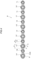
- FIG. 4 is a cross-sectional view perpendicular to a longitudinal direction of an optical fiber ribbon 1B according to a first modification.
- elements substantially the same as or corresponding to those in the configuration shown in FIG. 1 are denoted by the same reference numerals, and repeated description thereof will be omitted.
- the plurality of optical fibers 11 of the optical fiber ribbon 1B include first optical fibers each having an outer diameter D1 (an example of a first outer diameter), and second optical fibers each having an outer diameter D2 (an example of a second outer diameter).
- the outer diameter D1 of the first optical fibers 11A', 11C', 11E', 11G', 11I', and 11K' is different from the outer diameter D2 of the second optical fibers 11B, 11D, 11F, 11H, 11J, and 11L, and the first optical fibers each having the outer diameter D1 and the second optical fibers each having the outer diameter D2 are alternately arranged.
- the outer diameter D1 of the first optical fiber and the outer diameter D2 of the second optical fiber are both 215 ⁇ m or less.
- the outer diameter D1 is 200 ⁇ m
- the outer diameter D2 is 180 ⁇ m.
- Each of the first optical fibers 11A', 11C', 11E', 11G', 11I', and 11K' includes the glass fiber 12, the primary resin layer 13, and the secondary resin layer 14.
- the connected portions 21 of the collective coating layer 20 are also arranged such that the distance P between the centers of adjacent optical fibers is 220 ⁇ m or more and 280 ⁇ m or less.
- the collective coating layer 20 includes the thick portion 22 and at least two thin portions 23, similar to the optical fiber ribbon 1A.
- the second optical fibers 11B, 11D, 11F, 11H, 11J, and 11L each having the small outer diameter D2 are disposed in gaps between the first optical fibers 11A', 11C', 11E', 11G', 11I', and 11K' each having the large outer diameter D1. Accordingly, as compared with a case in which the plurality of optical fibers 11 have the same outer diameter, mounting density of the optical fibers 11 with respect to the optical fiber cable is higher in a case in which the plurality of optical fibers 11 have the outer diameters D1 and D2 different from each other.
- the thick portion 22 of each optical fiber may be disposed at a position facing the thin portion 23 of another optical fiber. Accordingly, as compared with a case in which the collective coating layer 20 has a uniform thickness, the mounting density of the optical fiber 11 with respect to the optical fiber cable is higher in a case in which the thick portion 22 and the thin portion 23 are provided.
- the optical fiber ribbon 1B according to the first modification includes the plurality of optical fibers 11 including the first optical fibers each having the outer diameter D1, and the second optical fibers each having the outer diameter D2, the optical fibers 11 can be mounted in the optical fiber cable at higher density.
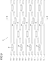
- FIG. 5 is a view showing an optical fiber ribbon 1C according to a second modification in a longitudinal direction.
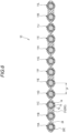
- FIG. 6 is a cross-sectional view of the optical fiber ribbon 1C.
- elements substantially the same as or corresponding to those in the configuration shown in FIG. 1 are denoted by the same reference numerals, and repeated description thereof will be omitted.
- a collective coating layer 20C of the optical fiber ribbon 1C includes non-connected portions 24 at each of which adjacent optical fiber ribbons are not connected in at least a part of the plurality of optical fibers 11.
- the non-connected portions 24 are formed between the optical fibers 11A and 11B, between the optical fibers 11C and 11D, between the optical fibers 11D and 11E, between the optical fibers 11F and 11G, between the optical fibers 11G and 11H, between the optical fibers 11I and 11J, and between the optical fibers 11J and 11K.
- the arrangement positions of the non-connected portions 24 shown in FIG. 6 is an example, and are not limited thereto.
- the non-connected portions 24 are intermittently formed in the longitudinal direction of the optical fiber ribbon 1C. Even when the non-connected portions 24 are formed, the optical fibers 11A to 11L are also arranged such that the distance P between centers of adjacent optical fibers is 220 ⁇ m or more and 280 ⁇ m or less.
- the non-connected portions 24 are intermittently formed in the longitudinal direction of the optical fiber ribbon 1C, deformability of the optical fiber ribbon 1C is enhanced in a cross section perpendicular to the longitudinal direction. Since the optical fiber ribbon 1C is easily deformed, a plurality of optical fiber ribbons 1C can be mounted in an optical fiber cable at high density.
- optical fibers 11 of the optical fiber ribbon 1C according to the second modification are all the same, the optical fibers 11 of the optical fiber ribbon 1C may have different outer diameters D1 and D2 as shown in the first modification.
- FIG. 7 is a cross-sectional view perpendicular to a longitudinal direction of an optical fiber ribbon 1X used in an evaluation experiment.
- elements substantially the same as or corresponding to those in the configuration shown in FIG. 4 or 6 are denoted by the same reference numerals, and repeated description thereof will be omitted.
- the optical fiber ribbon 1X used in the evaluation experiment includes four optical fibers 11A', 11B, 11C', and 11D.
- Each of the optical fibers includes the glass fiber 12, the primary resin layer 13, and the secondary resin layer 14.
- the outer diameter D1 of each of the optical fiber 11A' and 11C' is 200 ⁇ m.
- the outer diameter D2 of each of the optical fibers 11B and 11C is 180 ⁇ m.
- the optical fiber having the outer diameter D1 of 200 ⁇ m and the optical fiber having the outer diameter D2 of 180 ⁇ m are alternately arranged along a direction orthogonal to the longitudinal direction of the optical fiber ribbon 1X.
- outer peripheries of the four optical fibers 11A' to 11D arranged in parallel are coated with an ultraviolet curable resin. Thereafter, the ultraviolet curable resin is cured by being irradiated with ultraviolet rays, and the collective coating layer 20C is formed. At this time, the outer peripheries of the optical fibers 11A' to 11D are covered with the collective coating layer 20C.
- the thick portion 22 and the thin portion 23 are formed by adjusting a thickness of the applied ultraviolet curable resin by a shape of a die or the like.
- the non-connected portions 24 are formed by inserting a cleaving blade such as a cutter between the adjacent optical fibers 11A' and 11B and between the adjacent optical fibers 11C' and 11D intermittently in the longitudinal direction of the optical fiber ribbon 1X.
- the connected portion 21 remains between the optical fibers 11B and 11C' where no cleaving blade is inserted.
- samples No. 1 to No. 5 for the optical fiber ribbon 1X including various thicknesses of the collective coating layer 20C were prepared by adjusting the thickness of the applied ultraviolet curable resin.
- Samples No. 6 to No. 8 were prepared as comparative examples.
- the optical fiber 11A' was selected as any optical fiber of each sample, and the thickness of the collective coating layer 20C was measured at any eight measurement positions I to VIII in the optical fiber 11A'.
- the optical fiber ribbon 1X was mounted on an optical fiber cable, and the low-temperature characteristic of the optical fiber ribbon 1X was evaluated.
- the low-temperature characteristic was evaluated by measuring an attenuation amount per unit distance in a case in which light having a wavelength of 1.55 ⁇ m was incident on the fiber 11A' inside the cable under an environment of 23°C and an environment of -30°C, and evaluating a difference between measured values under the two temperature environments. Further, the optical fiber ribbon 1X was taken out from the optical fiber cable, and the presence or absence of the single core-separation of the optical fiber was examined. Evaluation results thereof are shown in Table 1. [Table 1] Sample No. 1 No. 2 No. 3 No. 4 No. 5 No. 6 No. 7 No.
- the optical fiber separation of the optical fiber ribbon 1X was not found.
- the fiber separation was not found.
- the measurement positions II, IV, VI, and VIII correspond to the thin portion 23, and the thickness of the collective coating layer 20C at each measurement position is 1 ⁇ m.
- the sample No. 6 as the comparative example, the single core-separation was found.
- the measurement positions I, III, V, and VII correspond to the thick portion 22, and the thickness of the collective coating layer 20C at each measurement position is 20 ⁇ m.
- the thickness of the collective coating layer 20C in the thin portion 23 of the sample No. 4 was 1 ⁇ m. It was confirmed that cable attenuation of the sample No. 4 was 0.3 dB/km or less. From the above, it was confirmed that the optical fiber ribbon 1X having low cable attenuation can be implemented when the difference between the thickness of the collective coating layer 20C in the thick portion 22 and the thickness of the collective coating layer 20C in the thin portion 23 is 19 ⁇ m or less.
- the cable attenuation of the samples No. 1 to No. 5 were all 0.3 dB/km or less, and it was confirmed that the low-temperature characteristic was good.
- the thicknesses of the collective coating layer 20C at the measurement positions IV and VII corresponding to the thin portions 23 are 5 ⁇ m.
- the cable attenuation of the sample No. 8 as the comparative example exceeded 0.3 dB/km.
- the thickness of the collective coating layer 20C at the measurement positions II corresponding to the thin portion 23 is 5 ⁇ m.
- the cable attenuation of the sample No. 1 including two thin portions 23 was small, whereas the cable attenuation of the sample No. 8 including only one thin portion 23 was larger than that of the sample No. 1.
- the optical fiber ribbon 1X having the small cable attenuation can be implemented.
- the cable attenuation of the sample No. 5 was 0.3 dB/km or less, whereas the cable attenuation of the sample No. 7 exceeded 0.3 dB/km.
- the measurement positions I, III, V, and VII correspond to the thick portion 22, and the measurement positions II, IV, VI, and VIII correspond to the thin portion 23.
- the thickness of the collective coating layer 20C in the thick portion 22 is 20 ⁇ m, and the thickness of the collective coating layer 20C in the thin portion 23 is 15 ⁇ m.
- the thickness of the collective coating layer 20C in the thick portion 22 is 20 ⁇ m, and the thickness of the collective coating layer 20C in the thin portion 23 is 17 ⁇ m.
- the difference between the thickness of the collective coating layer 20C in the thick portion 22 and the thickness of the collective coating layer 20C in the thin portion 23 is not sufficient, the friction between the optical fibers cannot be reduced. As a result, it was confirmed that the cable attenuation increased. From the above, it was confirmed that the optical fiber ribbon 1X having low cable attenuation can be implemented when the difference between the thickness of the collective coating layer 20C in the thick portion 22 and the thickness of the collective coating layer 20C in the thin portion 23 is 5 ⁇ m or more.
Landscapes
- Physics & Mathematics (AREA)
- General Physics & Mathematics (AREA)
- Optics & Photonics (AREA)
- Engineering & Computer Science (AREA)
- Manufacturing & Machinery (AREA)
- Mechanical Coupling Of Light Guides (AREA)
- Optical Fibers, Optical Fiber Cores, And Optical Fiber Bundles (AREA)
Abstract
Description
- The present disclosure relates to an optical fiber ribbon. The present application claims priority from
Japanese Patent Application No. 2020-175367 filed on October 19, 2020 - In recent years, there is an increasing demand to increase density of an optical fiber cable. As an example of increasing the density, it is known to reduce an outer diameter of an optical fiber to be mounted in the optical fiber cable or to use a plurality of optical fibers having different outer diameters. Further, in order to improve workability and identifiability at the time of splicing, there has been an optical fiber ribbon in which a plurality of optical fiber ribbons are arranged in parallel and integrally coated (Patent Literatures 1 and 2).
-
- Patent Literature 1:
JP2014-238480A - Patent Literature 2:
JP2014-219496A - An optical fiber ribbon according to the present disclosure includes:
- a plurality of optical fibers arranged in parallel in a direction orthogonal to a longitudinal direction of the plurality of optical fibers; and
- a collective coating layer covering an outer periphery of each of the plurality of optical fibers, in which
- the collective coating layer includes a connected portion at which the optical fibers adjacent to each other are connected in at least a part of the plurality of optical fibers,
- an outer diameter of each of the plurality of optical fibers is 215 µm or less,
- in a cross-sectional view of each of the optical fibers, the collective coating layer includes a thick portion and at least two thin portions in each of which a thickness of the collective coating layer is smaller than the thickness of the collective coating layer in the thick portion, and
- a difference between the thickness of the collective coating layer in the thick portion and the thickness of the collective coating layer in the thin portion is 5 µm or more and 19 µm or less.
-
- [
FIG. 1] FIG. 1 is a cross-sectional view of an optical fiber ribbon according to a first embodiment of the present disclosure. - [
FIG. 2] FIG. 2 is a cross-sectional view of an optical fiber of the optical fiber ribbon shown inFIG. 1 . - [
FIG. 3] FIG. 3 is a schematic view showing a relationship between a pitch of the optical fiber ribbon according to the first embodiment and V-grooves of a fusion machine in a fusion step. - [
FIG. 4] FIG. 4 is a cross-sectional view of an optical fiber ribbon according to a first modification. - [
FIG. 5] FIG. 5 is a view showing an optical fiber ribbon according to a second modification in a longitudinal direction. - [
FIG. 6] FIG. 6 is a cross-sectional view of the optical fiber ribbon shown inFIG. 5 . - [
FIG. 7] FIG. 7 is a cross-sectional view of an optical fiber ribbon used in an evaluation experiment. - In a case in which the optical fiber ribbons are mounted in the optical fiber cable at high density, since the optical fiber ribbons tend to be in contact with each other, friction may occur between the optical fiber ribbons. When the friction occurs non-uniformly in a longitudinal direction of the cable, the cable tends to meander. Further, transmission characteristics of the cable at a low temperature tend to deteriorate. In particular, in a case in which outer diameters of a plurality of optical fibers are different, the cable is more likely to meander, and the transmission characteristics are more likely to deteriorate.
- The present disclosure provides an optical fiber ribbon that enables high-density mounting of optical fibers in an optical fiber cable and prevents occurrence of cable meandering.
- First, an embodiment of the present disclosure will be listed and described.
- (1) An optical fiber ribbon according to an aspect of the present disclosure includes:
- a plurality of optical fibers arranged in parallel in a direction orthogonal to a longitudinal direction of the plurality of optical fibers; and
- a collective coating layer covering an outer periphery of each of the plurality of optical fibers, in which
- the collective coating layer includes a connected portion at which the optical fibers adjacent to each other are connected in at least a part of the plurality of optical fibers,
- an outer diameter of each of the plurality of optical fibers is 215 µm or less,
- in a cross-sectional view of each of the optical fibers, the collective coating layer includes a thick portion and at least two thin portions in each of which a thickness of the collective coating layer is smaller than the thickness of the collective coating layer in the thick portion, and
- a difference between the thickness of the collective coating layer in the thick portion and the thickness of the collective coating layer in the thin portion is 5 µm or more and 19 µm or less.
- In the optical fiber ribbon of the present disclosure, the collective coating layer includes the thick portion and at least two thin portions, and the thickness of the collective coating layer is non-uniform. In particular, since the difference between the thickness of the collective coating layer in the thick portion and the thickness of the collective coating layer in the thin portion is as relatively large as 5 µm or more and 19 µm or less, a contact area between the optical fiber ribbons can be reduced. Therefore, friction is unlikely to occur between the optical fiber ribbons adj acent to each other, and even when the optical fiber ribbons are mounted in a cable at high density, cable meandering can be further prevented.
- Further, according to the present disclosure, since the outer diameter of each optical fiber of the optical fiber ribbon is 215 µm or less, the optical fiber ribbons can be mounted in the cable at high density.
- (2) A distance between centers of the optical fibers adjacent to each other may be 220 µm or more and 280 µm or less.
- According to the present disclosure, since the distance between the centers of the optical fibers adjacent to each other is 220 µm or more and 280 µm or less, a general splicing device can be used. Even if each of the optical fibers is small in diameter, it is not necessary to prepare a dedicated splicing device for small-diameter optical fibers, so that a versatile optical fiber ribbon can be provided.
- (3) The collective coating layer may include a non-connected portion at which the optical fibers adj acent to each other are not connected in at least a part of the plurality of optical fibers.
- The connected portion may be formed intermittently in the longitudinal direction.
- According to the present disclosure, since the non-connected portion is provided intermittently in the longitudinal direction, the optical fiber ribbon is easily deformed in a cross section perpendicular to the longitudinal direction. Accordingly, the optical fibers can be mounted in the optical fiber cable at high density.
- (4) The plurality of optical fibers may include a first optical fiber having a first outer diameter and a second optical fiber having a second outer diameter.
- According to the present disclosure, since the plurality of optical fiber ribbons include the first optical fiber having the first outer diameter and the second optical fiber having the second outer diameter, the optical fibers can be mounted in the optical fiber cable at high density while preventing the cable meandering.
- According to the present disclosure, an optical fiber ribbon that enables high-density mounting of optical fibers in an optical fiber cable and prevents occurrence of cable meandering can be provided.
- Specific examples of an optical fiber ribbon according to a first embodiment of the present disclosure will be described with reference to the drawings.
- The present disclosure is not limited to these examples and is defined by the scope of the claims, and is intended to include all modifications within the scope and meaning equivalent to the scope of the claims.
-
FIG. 1 is a cross-sectional view perpendicular to a longitudinal direction of anoptical fiber ribbon 1A according to an embodiment of the present disclosure. As shown inFIG. 1 , theoptical fiber ribbon 1A includes a plurality of optical fibers 11 and acollective coating layer 20 that covers the plurality of optical fibers 11. In this example, 12optical fibers 11A to 11L are arranged in parallel in a direction orthogonal to the longitudinal direction of theoptical fiber ribbon 1A. The plurality of optical fibers 11 are arranged at regular intervals. Outer peripheries of the plurality of optical fibers 11 are covered with thecollective coating layer 20, and the entire optical fibers 11 are connected by thecollective coating layer 20. - An outer diameter D of each of the plurality of optical fibers 11 is 215 µm or less. In this example, the outer diameter D of each optical fiber is 200 µm. Each optical fiber 11 includes, for example, a
glass fiber 12 including a core and a cladding, aprimary resin layer 13 covering an outer periphery of theglass fiber 12, and asecondary resin layer 14 covering an outer periphery of theprimary resin layer 13. Theglass fiber 12 may include pure silica glass, silica glass doped with germanium, or silica glass doped with fluorine. Theprimary resin layer 13 may include a soft material having a relatively low Young's modulus, as a buffer layer. Thesecondary resin layer 14 may include a hard material having a relatively high Young's modulus, as a protective layer. - The Young's modulus of the
primary resin layer 13 at 23°C is preferably 0.04 MPa or more and 0.8 MPa or less, more preferably 0.05 MPa or more and 0.7 MPa or less, and still more preferably 0.05 MPa or more and 0.6 MPa or less. Since the Young's modulus of theprimary resin layer 13 is 0.04 MPa or more and 0.8 MPa or less, voids are less likely to be generated in the optical fiber. The Young's modulus of thesecondary resin layer 14 at 23°C is preferably 900 MPa or more, more preferably 1000 MPa or more, and still more preferably 1200 MPa or more. The Young's modulus of thesecondary resin layer 14 at 23°C may be 3000 MPa or less, 2500 MPa or less, 2000 MPa or less, or 1800 MPa or less. Since the Young's modulus of thesecondary resin layer 14 is 900 MPa or more, lateral pressure resistance is likely to be improved. When the Young's modulus of thesecondary resin layer 14 is 3000 MPa or less, since thesecondary resin layer 14 has appropriate elongation at break, stripping is easily performed. - The
collective coating layer 20 includes connectedportions 21 at each of which adjacent optical fibers are connected in at least a part of the plurality of optical fibers 11. In this example, theconnected portions 21 are disposed between all adjacent optical fibers. Theconnected portions 21 are disposed such that a distance P between centers of adjacent optical fibers is 220 µm or more and 280 µm or less. - The
collective coating layer 20 may contain, for example, an ultraviolet curable resin. A Young's modulus of thecollective coating layer 20 at 23°C is preferably 50 MPa or more and 900 MPa or less, and more preferably 100 MPa or more and 800 MPa or less, from the viewpoint of lateral pressure resistance and flexibility of the optical fiber ribbon. -
FIG. 2 is a cross-sectional view of oneoptical fiber 11B among the plurality of optical fibers 11 in theoptical fiber ribbon 1A shown inFIG. 1 . Since configurations of otheroptical fibers optical fiber 11B shown inFIG. 2 , repeated description will be omitted. - As shown in
FIG. 2 , in the cross-sectional view of theoptical fiber 11B, thecollective coating layer 20 includes athick portion 22 and at least twothin portions 23. In other words, a thickness of thecollective coating layer 20 is non-uniform on the outer periphery of theoptical fiber 11B. Here, the thickness of thecollective coating layer 20 on the outer periphery of theoptical fiber 11B is measured at a total of five locations except for the connectedportion 21. Among the five locations, a portion around a location where the thickness of thecollective coating layer 20 is largest is defined as thethick portion 22, and a portion around a location where the thickness of thecollective coating layer 20 is thinner than thethick portion 22 by 5 µm or more is defined as thethin portion 23. Positions of thethick portion 22 and thethin portion 23 on the outer periphery of theoptical fiber 11B shown inFIG. 2 are merely examples, and the present disclosure is not limited thereto. Further, since thecollective coating layer 20 covers the outer periphery of theoptical fiber 11B, there is no location where theoptical fiber 11B is exposed from thecollective coating layer 20. - A thickness d2 of the
collective coating layer 20 in thethin portion 23 is smaller than a thickness d1 of thecollective coating layer 20 in thethick portion 22. Specifically, a difference between the thickness d1 of thecollective coating layer 20 in thethick portion 22 and the thickness d2 of thecollective coating layer 20 in thethin portion 23 is 5 µm or more and 19 µm or less. The thickness d1 of thecollective coating layer 20 in thethick portion 22 is, for example, 20 µm or less. The thickness d2 of thecollective coating layer 20 in thethin portion 23 is, for example, 1 µm or more and 15 µm or less. In this example, the thickness of the collective coating layer between theoptical fiber 11B and theoptical fiber portion 21. - Next, fusion splicing of the
optical fiber ribbon 1A will be described. In general, in a case of splicing the optical fiber ribbon and another fiber ribbon, the plurality of optical fibers can be wholly fusion-spliced by using a multi-optical fiber fusion splicer (not shown).FIG. 3 is a schematic view showing a relationship between a pitch of theoptical fiber ribbon 1A (distance P between the centers of the adjacent optical fibers) and a V-groove base 30 of the fusion machine. As shown inFIG. 3 , the fusion splicer includes the V-groove base 30 including a plurality of V-grooves 31 in which the plurality of optical fibers 11 are arranged. In this example, the 12optical fibers 11A to 11L are respectively arranged in 12 V-grooves 31A to 31L. A pitch P0 of the V-grooves 31A to 31L is 250 µm according to an international standard of an outer diameter of the optical fiber. - At the time of fusion-splicing, the
optical fibers 11A to 11L in a state in which thecollective coating layer 20 is stripped are arranged above the V-groove base 30. Theoptical fibers 11A to 11L are arranged such that, for example, center positions of the V-grooves 31A to 31L in a parallel arrangement direction and center positions of theoptical fibers 11A to 11L in a parallel arrangement direction are aligned. In this state, a clamp cover (not shown) of the multi optical fiber fusion splicer is closed, and theoptical fibers 11A to 11L are pushed down from above by the clamp cover. - If there is no connected portion in the optical fiber ribbon and a distance between centers of adjacent optical fibers among the optical fibers is zero, the distance between the centers is smaller than the pitch P0 of the V-
grooves 31A to 31L. In this case, the plurality of optical fibers are arranged in a manner of being gathered toward a center position of the V-groove base 30, and are not arranged in a manner of facing the V-grooves 31A to 31L. Accordingly, the plurality of optical fibers are not necessarily accommodated in the V-grooves 31A to 31L, respectively, and for example, a case in which the optical fibers are not accommodated in the V-grooves - On the other hand, in the
optical fiber ribbon 1A in this example, since theconnected portions 21 are arranged such that the distance P between the centers of adjacent optical fibers is 220 µm or more and 280 µm or less, theoptical fibers 11A to 11L are arranged in a manner of facing the V-grooves 31Ato 31L respectively. Therefore, when theoptical fibers 11A to 11L are pushed down substantially vertically, theoptical fibers 11A to 11L are accommodated in the V-grooves 31A to 31L respectively. -
FIG. 3 shows that theoptical fibers 11A to 11L in a state in which thecollective coating layer 20 is stripped are to be accommodated in the V-grooves 31A to 31L respectively, but for example, theprimary resin layer 13 and thesecondary resin layer 14 may be further stripped in addition to thecollective coating layer 20, and only theglass fiber 12 may be accommodated in each of the V-grooves 31A to 31L. - As described above, in the
optical fiber ribbon 1A according to this example, thecollective coating layer 20 includes thethick portion 22 and at least twothin portions 23, and the thickness of thecollective coating layer 20 is non-uniform. In particular, since the difference between the thickness d1 of thecollective coating layer 20 in thethick portion 22 and the thickness d2 of thecollective coating layer 20 in thethin portion 23 is as relatively large as 5 µm or more and 19 µm or less, even when a plurality ofoptical fiber ribbon 1A are mounted in an optical fiber cable at high density, a contact area between the optical fibers in adjacentoptical fiber ribbons 1A and a contact area between the optical fiber ribbons can be reduced. Accordingly, friction is less likely to occur between adjacent optical fiber ribbons, cable meandering can be prevented, and cable laying work can be improved. - In the
optical fiber ribbon 1A of this example, thecollective coating layer 20 covers the outer peripheries of the plurality of optical fibers. If the outer periphery of any optical fiber 11 is not completely covered with thecollective coating layer 20 and there is a portion exposed from thecollective coating layer 20, thecollective coating layer 20 may be peeled off from the optical fiber 11 starting from the exposed portion, and as a result, the optical fiber 11 may be single core-separated from the optical fiber ribbon. However, in this example, since the outer peripheries of the plurality of optical fibers are covered with thecollective coating layer 20, the single core-separation does not occur. - Since the outer diameter of each optical fiber 11 of the
optical fiber ribbon 1A of this example is 215 µm or less, a cross-sectional area of the optical fiber 11 is small, and theoptical fiber ribbons 1A can be mounted in an optical fiber cable at high density. - In this example, since the distance between the centers of adjacent optical fibers is 220 µm or more and 280 µm or less, the optical fiber ribbon can be used in a general multi-core fusion machine or splicing device. Even if each of the optical fibers 11 is small in diameter, it is not necessary to prepare a multi-core fusion machine dedicated to small-diameter fibers, such as a multi-core fusion machine in which V-grooves are formed at a narrow pitch, so that versatility of the
optical fiber ribbon 1A is high and a manufacturing cost can be reduced. - In the
optical fiber ribbon 1A according to the first embodiment, the outer diameters of the optical fibers 11 are all the same, but the outer diameters of the optical fibers 11 may not be the same.FIG. 4 is a cross-sectional view perpendicular to a longitudinal direction of anoptical fiber ribbon 1B according to a first modification. In the description ofFIG. 4 , elements substantially the same as or corresponding to those in the configuration shown inFIG. 1 are denoted by the same reference numerals, and repeated description thereof will be omitted. - As shown in
FIG. 4 , the plurality of optical fibers 11 of theoptical fiber ribbon 1B include first optical fibers each having an outer diameter D1 (an example of a first outer diameter), and second optical fibers each having an outer diameter D2 (an example of a second outer diameter). In this example, the outer diameter D1 of the firstoptical fibers 11A', 11C', 11E', 11G', 11I', and 11K' is different from the outer diameter D2 of the secondoptical fibers optical fibers 11A', 11C', 11E', 11G', 11I', and 11K' includes theglass fiber 12, theprimary resin layer 13, and thesecondary resin layer 14. Further, when the outer diameters D1 and D2 are different from each other, theconnected portions 21 of thecollective coating layer 20 are also arranged such that the distance P between the centers of adjacent optical fibers is 220 µm or more and 280 µm or less. Further, thecollective coating layer 20 includes thethick portion 22 and at least twothin portions 23, similar to theoptical fiber ribbon 1A. - When the
optical fiber ribbon 1B according to the first modification is mounted in an optical fiber cable, the secondoptical fibers optical fibers 11A', 11C', 11E', 11G', 11I', and 11K' each having the large outer diameter D1. Accordingly, as compared with a case in which the plurality of optical fibers 11 have the same outer diameter, mounting density of the optical fibers 11 with respect to the optical fiber cable is higher in a case in which the plurality of optical fibers 11 have the outer diameters D1 and D2 different from each other. Furthermore, thethick portion 22 of each optical fiber may be disposed at a position facing thethin portion 23 of another optical fiber. Accordingly, as compared with a case in which thecollective coating layer 20 has a uniform thickness, the mounting density of the optical fiber 11 with respect to the optical fiber cable is higher in a case in which thethick portion 22 and thethin portion 23 are provided. - As described above, since the
optical fiber ribbon 1B according to the first modification includes the plurality of optical fibers 11 including the first optical fibers each having the outer diameter D1, and the second optical fibers each having the outer diameter D2, the optical fibers 11 can be mounted in the optical fiber cable at higher density. - The
connected portions 21 of theoptical fiber ribbon 1A according to the first embodiment connect all adjacent optical fibers, but the arrangement of the connected portions is not limited thereto.FIG. 5 is a view showing anoptical fiber ribbon 1C according to a second modification in a longitudinal direction.FIG. 6 is a cross-sectional view of theoptical fiber ribbon 1C. In the description ofFIG. 6 , elements substantially the same as or corresponding to those in the configuration shown inFIG. 1 are denoted by the same reference numerals, and repeated description thereof will be omitted. - As shown in
FIGS. 5 and6 , acollective coating layer 20C of theoptical fiber ribbon 1C includesnon-connected portions 24 at each of which adjacent optical fiber ribbons are not connected in at least a part of the plurality of optical fibers 11. In the second modification, thenon-connected portions 24 are formed between theoptical fibers optical fibers optical fibers optical fibers optical fibers optical fibers optical fibers non-connected portions 24 shown inFIG. 6 is an example, and are not limited thereto. Thenon-connected portions 24 are intermittently formed in the longitudinal direction of theoptical fiber ribbon 1C. Even when thenon-connected portions 24 are formed, theoptical fibers 11A to 11L are also arranged such that the distance P between centers of adjacent optical fibers is 220 µm or more and 280 µm or less. - As described above, according to the
optical fiber ribbon 1C of the second modification, since thenon-connected portions 24 are intermittently formed in the longitudinal direction of theoptical fiber ribbon 1C, deformability of theoptical fiber ribbon 1C is enhanced in a cross section perpendicular to the longitudinal direction. Since theoptical fiber ribbon 1C is easily deformed, a plurality ofoptical fiber ribbons 1C can be mounted in an optical fiber cable at high density. - Although outer diameters of the optical fibers 11 of the
optical fiber ribbon 1C according to the second modification are all the same, the optical fibers 11 of theoptical fiber ribbon 1C may have different outer diameters D1 and D2 as shown in the first modification. - A low-temperature characteristic and the presence or absence of single core-separation of the optical fiber ribbon of the present disclosure were evaluated.
FIG. 7 is a cross-sectional view perpendicular to a longitudinal direction of anoptical fiber ribbon 1X used in an evaluation experiment. In the description ofFIG. 7 , elements substantially the same as or corresponding to those in the configuration shown inFIG. 4 or6 are denoted by the same reference numerals, and repeated description thereof will be omitted. - As shown in
FIG. 7 , theoptical fiber ribbon 1X used in the evaluation experiment includes fouroptical fibers 11A', 11B, 11C', and 11D. Each of the optical fibers includes theglass fiber 12, theprimary resin layer 13, and thesecondary resin layer 14. The outer diameter D1 of each of theoptical fiber 11A' and 11C' is 200 µm. The outer diameter D2 of each of theoptical fibers optical fiber ribbon 1X. - In manufacturing steps of the
optical fiber ribbon 1X, outer peripheries of the fouroptical fibers 11A' to 11D arranged in parallel are coated with an ultraviolet curable resin. Thereafter, the ultraviolet curable resin is cured by being irradiated with ultraviolet rays, and thecollective coating layer 20C is formed. At this time, the outer peripheries of theoptical fibers 11A' to 11D are covered with thecollective coating layer 20C. Thethick portion 22 and thethin portion 23 are formed by adjusting a thickness of the applied ultraviolet curable resin by a shape of a die or the like. Further, after the ultraviolet curable resin is cured and theconnected portions 21 are formed between all the adjacent optical fibers, thenon-connected portions 24 are formed by inserting a cleaving blade such as a cutter between the adjacentoptical fibers 11A' and 11B and between the adjacentoptical fibers 11C' and 11D intermittently in the longitudinal direction of theoptical fiber ribbon 1X. The connectedportion 21 remains between theoptical fibers - In the evaluation experiment, samples No. 1 to No. 5 for the
optical fiber ribbon 1X including various thicknesses of thecollective coating layer 20C were prepared by adjusting the thickness of the applied ultraviolet curable resin. Samples No. 6 to No. 8 were prepared as comparative examples. In the evaluation experiment, theoptical fiber 11A' was selected as any optical fiber of each sample, and the thickness of thecollective coating layer 20C was measured at any eight measurement positions I to VIII in theoptical fiber 11A'. Further, theoptical fiber ribbon 1X was mounted on an optical fiber cable, and the low-temperature characteristic of theoptical fiber ribbon 1X was evaluated. Here, the low-temperature characteristic was evaluated by measuring an attenuation amount per unit distance in a case in which light having a wavelength of 1.55 µm was incident on thefiber 11A' inside the cable under an environment of 23°C and an environment of -30°C, and evaluating a difference between measured values under the two temperature environments. Further, theoptical fiber ribbon 1X was taken out from the optical fiber cable, and the presence or absence of the single core-separation of the optical fiber was examined. Evaluation results thereof are shown in Table 1.[Table 1] Sample No. 1 No. 2 No. 3 No. 4 No. 5 No. 6 No. 7 No. 8 Thickness of collective coating layer (µm) I 20 20 20 20 20 20 20 20 II 20 20 5 1 15 0 17 5 III 20 20 20 20 20 20 20 20 IV 5 5 5 1 15 0 17 20 V 20 20 20 20 20 20 20 20 VI 5 5 5 1 15 20 17 20 VII 20 20 20 20 20 20 20 20 VIII 20 5 5 1 15 20 17 20 Low-temperature characteristic 0.3 dB/km or less 0.3 dB/km or less 0.3 dB/km or less 0.3 dB/km or less 0.3 dB/km or less 0.3 dB/km or less Exceed 0.3 dB/km Exceed 0.3 dB/km Presence or absence of optical fiber separation Absence Absence Absence Absence Absence Presence Absence Absence - As shown in Table 1, in the samples No. 1 to No. 5, the optical fiber separation of the
optical fiber ribbon 1X was not found. In particular, in the sample No. 4, the fiber separation was not found. In the sample No. 4, the measurement positions II, IV, VI, and VIII correspond to thethin portion 23, and the thickness of thecollective coating layer 20C at each measurement position is 1 µm. On the other hand, in the sample No. 6 as the comparative example, the single core-separation was found. The sample No. 6 includes two portions where the thicknesses of thecollective coating layer 20C are zero at the measurement positions II and IV Portions at which theoptical fiber 11A' is not covered with thecollective coating layer 20C and is exposed from thecollective coating layer 20C are at the measurement positions II and IV It was confirmed that thecollective coating layer 20C was peeled off from theoptical fiber 11A' starting from the exposed portion, and as a result, theoptical fiber 11A' was separated from theoptical fiber ribbon 1X. From the above, it was confirmed that when the outer peripheries of the plurality of optical fibers 11 were covered with thecollective coating layer 20C, there was no fiber separation. - In the sample No. 4, the measurement positions I, III, V, and VII correspond to the
thick portion 22, and the thickness of thecollective coating layer 20C at each measurement position is 20 µm. The thickness of thecollective coating layer 20C in thethin portion 23 of the sample No. 4 was 1 µm. It was confirmed that cable attenuation of the sample No. 4 was 0.3 dB/km or less. From the above, it was confirmed that theoptical fiber ribbon 1X having low cable attenuation can be implemented when the difference between the thickness of thecollective coating layer 20C in thethick portion 22 and the thickness of thecollective coating layer 20C in thethin portion 23 is 19 µm or less. - As shown in Table 1, the cable attenuation of the samples No. 1 to No. 5 were all 0.3 dB/km or less, and it was confirmed that the low-temperature characteristic was good. In particular, in the sample No. 1, the thicknesses of the
collective coating layer 20C at the measurement positions IV and VII corresponding to thethin portions 23 are 5 µm. On the other hand, the cable attenuation of the sample No. 8 as the comparative example exceeded 0.3 dB/km. In the sample No. 8, the thickness of thecollective coating layer 20C at the measurement positions II corresponding to thethin portion 23 is 5 µm. In other words, the cable attenuation of the sample No. 1 including twothin portions 23 was small, whereas the cable attenuation of the sample No. 8 including only onethin portion 23 was larger than that of the sample No. 1. As described above, it was confirmed that when thecollective coating layer 20C of each optical fiber 11 includes at least two thin portions, theoptical fiber ribbon 1X having the small cable attenuation can be implemented. - As shown in Table 1, it was confirmed that the cable attenuation of the sample No. 5 was 0.3 dB/km or less, whereas the cable attenuation of the sample No. 7 exceeded 0.3 dB/km. In the samples No. 5 and No. 7, the measurement positions I, III, V, and VII correspond to the
thick portion 22, and the measurement positions II, IV, VI, and VIII correspond to thethin portion 23. In the sample No. 5, the thickness of thecollective coating layer 20C in thethick portion 22 is 20 µm, and the thickness of thecollective coating layer 20C in thethin portion 23 is 15 µm. On the other hand, in the sample No. 7, the thickness of thecollective coating layer 20C in thethick portion 22 is 20 µm, and the thickness of thecollective coating layer 20C in thethin portion 23 is 17 µm. In the sample No. 7, since the difference between the thickness of thecollective coating layer 20C in thethick portion 22 and the thickness of thecollective coating layer 20C in thethin portion 23 is not sufficient, the friction between the optical fibers cannot be reduced. As a result, it was confirmed that the cable attenuation increased. From the above, it was confirmed that theoptical fiber ribbon 1X having low cable attenuation can be implemented when the difference between the thickness of thecollective coating layer 20C in thethick portion 22 and the thickness of thecollective coating layer 20C in thethin portion 23 is 5 µm or more. - Although the present disclosure has been described in detail with reference to specific embodiments, it will be apparent to those skilled in the art that various changes and modifications can be made without departing from the spirit and scope of the present disclosure. The numbers, positions, shapes or the like of components described above are not limited to the above embodiment, and can be changed to suitable numbers, positions, shapes or the like during carrying out the present disclosure.
-
- 1A, 1B, 1C, 1X optical fiber ribbon
- 11, 11A to 11L optical fiber
- 12 glass fiber
- 13 primary resin layer
- 14 secondary resin layer
- 20, 20C collective coating layer
- 21 connected portion
- 22 thick portion
- 23 thin portion
- 24 non-connected portion
- 30 V-groove base
- 31, 31A to 31L V-groove
- D, D1, D2 outer diameter of optical fiber
- P distance between centers of adjacent optical fiber ribbons
- P0 V-groove pitch
- d1 thickness of collective coating layer in thick portion
- d2 thickness of collective coating layer in thin portion
Claims (4)
- An optical fiber ribbon comprising:a plurality of optical fibers arranged in parallel in a direction orthogonal to a longitudinal direction of the plurality of optical fibers; anda collective coating layer covering an outer periphery of each of the plurality of optical fibers, whereinthe collective coating layer includes a connected portion at which the optical fibers adjacent to each other are connected in at least a part of the plurality of optical fibers,an outer diameter of each of the plurality of optical fibers is 215 µm or less,in a cross-sectional view of each of the optical fibers, the collective coating layer includes a thick portion and at least two thin portions in each of which a thickness of the collective coating layer is smaller than a thickness of the collective coating layer in the thick portion, anda difference between the thickness of the collective coating layer in the thick portion and the thickness of the collective coating layer in the thin portion is 5 µm or more and 19 µm or less.
- The optical fiber ribbon according to claim 1, wherein
a distance between centers of the adjacent optical fibers is 220 µm or more and 280 µm or less. - The optical fiber ribbon according to claim 1 or 2, whereinthe collective coating layer includes a non-connected portion at which the optical fibers adjacent to each other are not connected in at least a part of the plurality of optical fibers, andthe connected portion is formed intermittently in the longitudinal direction.
- The optical fiber ribbon according to any one of claims 1 to 3, wherein
the plurality of optical fibers includes a first optical fiber having a first outer diameter and a second optical fiber having a second outer diameter.
Applications Claiming Priority (2)
| Application Number | Priority Date | Filing Date | Title |
|---|---|---|---|
| JP2020175367 | 2020-10-19 | ||
| PCT/JP2021/038286 WO2022085595A1 (en) | 2020-10-19 | 2021-10-15 | Optical fiber ribbon |
Publications (3)
| Publication Number | Publication Date |
|---|---|
| EP4231073A1 true EP4231073A1 (en) | 2023-08-23 |
| EP4231073A4 EP4231073A4 (en) | 2024-04-17 |
| EP4231073B1 EP4231073B1 (en) | 2026-01-28 |
Family
ID=81290508
Family Applications (1)
| Application Number | Title | Priority Date | Filing Date |
|---|---|---|---|
| EP21882736.8A Active EP4231073B1 (en) | 2020-10-19 | 2021-10-15 | Optical fiber ribbon |
Country Status (5)
| Country | Link |
|---|---|
| US (1) | US12529857B2 (en) |
| EP (1) | EP4231073B1 (en) |
| JP (1) | JP7816160B2 (en) |
| CN (1) | CN116420102A (en) |
| WO (1) | WO2022085595A1 (en) |
Cited By (1)
| Publication number | Priority date | Publication date | Assignee | Title |
|---|---|---|---|---|
| EP4556977A4 (en) * | 2022-07-13 | 2025-10-29 | Sumitomo Electric Industries | FIBER OPTICAL TAPE AND OPTICAL CABLE |
Families Citing this family (1)
| Publication number | Priority date | Publication date | Assignee | Title |
|---|---|---|---|---|
| IT202300014184A1 (en) * | 2023-07-06 | 2025-01-06 | Prysmian Spa | Optical cable module |
Family Cites Families (26)
| Publication number | Priority date | Publication date | Assignee | Title |
|---|---|---|---|---|
| TW420757B (en) * | 1996-11-18 | 2001-02-01 | Sumitomo Electric Industries | Divided type optical fiber tape core wires |
| US6097866A (en) * | 1998-05-01 | 2000-08-01 | Alcatel | Optical fiber ribbon |
| CA2339009C (en) * | 1999-06-03 | 2008-10-14 | Ube-Nitto Kasei Co., Ltd. | Spacer for optical fiber cable, method for producing said spacer, and optical fiber cable using said spacer |
| US6748148B2 (en) | 2002-05-31 | 2004-06-08 | Corning Cable Systems Llc | Optical fiber ribbons having a non-uniform thickness and/or preferential tear portions |
| JP4795288B2 (en) * | 2007-03-26 | 2011-10-19 | 古河電気工業株式会社 | Unit type optical fiber ribbon |
| CN102681119B (en) * | 2008-06-30 | 2015-01-28 | 日本电信电话株式会社 | Optical fiber cable and optical fiber ribbon |
| JP2011232733A (en) * | 2010-04-07 | 2011-11-17 | Sumitomo Electric Ind Ltd | Coated optical fiber ribbon, optical fiber cable and manufacturing method for coated optical fiber ribbon |
| JP5564026B2 (en) | 2011-10-18 | 2014-07-30 | 株式会社フジクラ | Optical fiber tape core and optical fiber cable storing the optical fiber core |
| JP5450687B2 (en) | 2012-02-15 | 2014-03-26 | 昭和電線ケーブルシステム株式会社 | Optical fiber ribbon manufacturing method and optical fiber ribbon manufacturing apparatus |
| JP5465741B2 (en) * | 2012-02-17 | 2014-04-09 | 古河電気工業株式会社 | Optical fiber core, optical fiber tape core and optical cable |
| JP2013221966A (en) * | 2012-04-13 | 2013-10-28 | Sumitomo Electric Ind Ltd | Optical fiber ribbon and optical fiber cable |
| JP2014211512A (en) * | 2013-04-18 | 2014-11-13 | 住友電気工業株式会社 | Optical fiber cord |
| JP5852045B2 (en) | 2013-05-07 | 2016-02-03 | 株式会社フジクラ | Optical fiber ribbon and optical fiber cable |
| JP6083803B2 (en) * | 2013-06-07 | 2017-02-22 | 株式会社フジクラ | Tape core |
| JP5802309B2 (en) * | 2014-06-06 | 2015-10-28 | 株式会社フジクラ | Optical fiber tape core and optical fiber cable storing the optical fiber core |
| CN107076945A (en) * | 2014-10-17 | 2017-08-18 | 住友电气工业株式会社 | Optical fibre core and optical fiber core |
| JP6440591B2 (en) * | 2015-08-06 | 2018-12-19 | 古河電気工業株式会社 | Optical fiber ribbon, optical fiber cable |
| WO2017095541A1 (en) * | 2015-11-30 | 2017-06-08 | Corning Optical Communications LLC | Flexible optical fiber ribbon with ribbon body flexibility recesses |
| JP2017219691A (en) * | 2016-06-07 | 2017-12-14 | 旭硝子株式会社 | Plastic optical fiber ribbon |
| JP2018035048A (en) | 2016-09-02 | 2018-03-08 | 住友電気工業株式会社 | Manufacturing method of striate body and manufacturing device of striate body |
| JP7052727B2 (en) * | 2016-12-06 | 2022-04-12 | 住友電気工業株式会社 | Intermittent connection type optical fiber tape core wire, its manufacturing method, optical fiber cable and optical fiber cord |
| US20190293891A1 (en) * | 2016-12-13 | 2019-09-26 | Corning Research & Development Corporation | Drop cable with attachment webbing |
| US20190219783A1 (en) * | 2018-01-12 | 2019-07-18 | Ofs Fitel, Llc | Multi-fiber unit tube optical fiber microcable incorporating rollable optical fibers ribbons |
| AU2020247710B2 (en) * | 2019-03-28 | 2023-02-16 | Corning Research & Development Corporation | Colored ribbon with discrete color layers |
| CN110193430A (en) | 2019-04-17 | 2019-09-03 | 厦门磊莎茶具有限公司 | A kind of Centrifuge Cup |
| CN111175887A (en) * | 2020-02-13 | 2020-05-19 | 江苏亨通光电股份有限公司 | Optical fiber ribbon, optical cable, and method for manufacturing optical fiber ribbon |
-
2021
- 2021-10-15 WO PCT/JP2021/038286 patent/WO2022085595A1/en not_active Ceased
- 2021-10-15 US US18/249,285 patent/US12529857B2/en active Active
- 2021-10-15 JP JP2022557489A patent/JP7816160B2/en active Active
- 2021-10-15 EP EP21882736.8A patent/EP4231073B1/en active Active
- 2021-10-15 CN CN202180070917.7A patent/CN116420102A/en active Pending
Cited By (1)
| Publication number | Priority date | Publication date | Assignee | Title |
|---|---|---|---|---|
| EP4556977A4 (en) * | 2022-07-13 | 2025-10-29 | Sumitomo Electric Industries | FIBER OPTICAL TAPE AND OPTICAL CABLE |
Also Published As
| Publication number | Publication date |
|---|---|
| EP4231073A4 (en) | 2024-04-17 |
| EP4231073B1 (en) | 2026-01-28 |
| US12529857B2 (en) | 2026-01-20 |
| CN116420102A (en) | 2023-07-11 |
| US20230400653A1 (en) | 2023-12-14 |
| WO2022085595A1 (en) | 2022-04-28 |
| JPWO2022085595A1 (en) | 2022-04-28 |
| JP7816160B2 (en) | 2026-02-18 |
Similar Documents
| Publication | Publication Date | Title |
|---|---|---|
| CN100365458C (en) | Peelable cushioning layer with preferential tearing portion and method of making the same | |
| US7050688B2 (en) | Fiber optic articles, assemblies, and cables having optical waveguides | |
| US7471862B2 (en) | Dry fiber optic cables and assemblies | |
| EP2946238B1 (en) | Fiber optic ribbon cable | |
| US20060291787A1 (en) | Fiber optic cable having strength component | |
| US7242841B2 (en) | Cross-connect fiber optic cables and associated cross-connect sections | |
| EP0853248A2 (en) | Buffered optical fiber | |
| CN1190469A (en) | Fiber optic ribbon cable and method for its manufacture | |
| WO2006107687A1 (en) | Fiber optic drop cables suitable for outdoor fiber to the subscriber applications | |
| WO2008016642A2 (en) | Fiber optic cables and assemblies suitable for distribution | |
| CN113316733B (en) | Intermittent connection type optical fiber ribbon core wire, optical fiber cable and manufacturing method of intermittent connection type optical fiber ribbon core wire | |
| EP4231073B1 (en) | Optical fiber ribbon | |
| WO2006108031A1 (en) | Protective casings for optical fibers | |
| EP3978976B1 (en) | Optical fiber tape core wire, optical fiber cable, and method of manufacturing optical fiber tape core wire | |
| CN100549742C (en) | Optical interconnect device | |
| EP3943992B1 (en) | Intermittent connection-type optical fiber tape core, optical fiber cable and connector-equipped optical fiber cord | |
| US20050084221A1 (en) | Apparatus and method for transitioning fiber optic cables | |
| KR20130106818A (en) | Plastic optical fiber unit and plastic optical fiber cable using same | |
| US20140090538A1 (en) | Method for stripping long segments of buffered optical fiber and a tool for performing the same | |
| EP4231074A1 (en) | Optical fiber ribbon | |
| EP3869251A1 (en) | Optical fiber cable | |
| EP4579304A1 (en) | Optical fiber cable with multifibre tight-buffered unit |
Legal Events
| Date | Code | Title | Description |
|---|---|---|---|
| STAA | Information on the status of an ep patent application or granted ep patent |
Free format text: STATUS: THE INTERNATIONAL PUBLICATION HAS BEEN MADE |
|
| PUAI | Public reference made under article 153(3) epc to a published international application that has entered the european phase |
Free format text: ORIGINAL CODE: 0009012 |
|
| STAA | Information on the status of an ep patent application or granted ep patent |
Free format text: STATUS: REQUEST FOR EXAMINATION WAS MADE |
|
| 17P | Request for examination filed |
Effective date: 20230419 |
|
| AK | Designated contracting states |
Kind code of ref document: A1 Designated state(s): AL AT BE BG CH CY CZ DE DK EE ES FI FR GB GR HR HU IE IS IT LI LT LU LV MC MK MT NL NO PL PT RO RS SE SI SK SM TR |
|
| DAV | Request for validation of the european patent (deleted) | ||
| DAX | Request for extension of the european patent (deleted) | ||
| A4 | Supplementary search report drawn up and despatched |
Effective date: 20240315 |
|
| RIC1 | Information provided on ipc code assigned before grant |
Ipc: G02B 6/44 20060101AFI20240311BHEP |
|
| GRAP | Despatch of communication of intention to grant a patent |
Free format text: ORIGINAL CODE: EPIDOSNIGR1 |
|
| STAA | Information on the status of an ep patent application or granted ep patent |
Free format text: STATUS: GRANT OF PATENT IS INTENDED |
|
| INTG | Intention to grant announced |
Effective date: 20250813 |
|
| GRAS | Grant fee paid |
Free format text: ORIGINAL CODE: EPIDOSNIGR3 |
|
| GRAA | (expected) grant |
Free format text: ORIGINAL CODE: 0009210 |
|
| STAA | Information on the status of an ep patent application or granted ep patent |
Free format text: STATUS: THE PATENT HAS BEEN GRANTED |
|
| P01 | Opt-out of the competence of the unified patent court (upc) registered |
Free format text: CASE NUMBER: UPC_APP_0016550_4231073/2025 Effective date: 20251210 |
|
| AK | Designated contracting states |
Kind code of ref document: B1 Designated state(s): AL AT BE BG CH CY CZ DE DK EE ES FI FR GB GR HR HU IE IS IT LI LT LU LV MC MK MT NL NO PL PT RO RS SE SI SK SM TR |
|
| REG | Reference to a national code |
Ref country code: CH Ref legal event code: F10 Free format text: ST27 STATUS EVENT CODE: U-0-0-F10-F00 (AS PROVIDED BY THE NATIONAL OFFICE) Effective date: 20260128 Ref country code: GB Ref legal event code: FG4D |
|
| REG | Reference to a national code |
Ref country code: DE Ref legal event code: R096 Ref document number: 602021047294 Country of ref document: DE |
|
| REG | Reference to a national code |
Ref country code: IE Ref legal event code: FG4D |
|
| REG | Reference to a national code |
Ref country code: NL Ref legal event code: MP Effective date: 20260128 |
|
| PG25 | Lapsed in a contracting state [announced via postgrant information from national office to epo] |
Ref country code: NL Free format text: LAPSE BECAUSE OF FAILURE TO SUBMIT A TRANSLATION OF THE DESCRIPTION OR TO PAY THE FEE WITHIN THE PRESCRIBED TIME-LIMIT Effective date: 20260128 |
|
| REG | Reference to a national code |
Ref country code: AT Ref legal event code: MK05 Ref document number: 1882017 Country of ref document: AT Kind code of ref document: T Effective date: 20260128 |
|
| PG25 | Lapsed in a contracting state [announced via postgrant information from national office to epo] |
Ref country code: RS Free format text: LAPSE BECAUSE OF FAILURE TO SUBMIT A TRANSLATION OF THE DESCRIPTION OR TO PAY THE FEE WITHIN THE PRESCRIBED TIME-LIMIT Effective date: 20260428 |
|
| PG25 | Lapsed in a contracting state [announced via postgrant information from national office to epo] |
Ref country code: ES Free format text: LAPSE BECAUSE OF FAILURE TO SUBMIT A TRANSLATION OF THE DESCRIPTION OR TO PAY THE FEE WITHIN THE PRESCRIBED TIME-LIMIT Effective date: 20260128 |
|
| PG25 | Lapsed in a contracting state [announced via postgrant information from national office to epo] |
Ref country code: PL Free format text: LAPSE BECAUSE OF FAILURE TO SUBMIT A TRANSLATION OF THE DESCRIPTION OR TO PAY THE FEE WITHIN THE PRESCRIBED TIME-LIMIT Effective date: 20260128 |
|
| PG25 | Lapsed in a contracting state [announced via postgrant information from national office to epo] |
Ref country code: GR Free format text: LAPSE BECAUSE OF FAILURE TO SUBMIT A TRANSLATION OF THE DESCRIPTION OR TO PAY THE FEE WITHIN THE PRESCRIBED TIME-LIMIT Effective date: 20260429 |
|
| REG | Reference to a national code |
Ref country code: LT Ref legal event code: MG9D |
|
| PG25 | Lapsed in a contracting state [announced via postgrant information from national office to epo] |
Ref country code: LT Free format text: LAPSE BECAUSE OF FAILURE TO SUBMIT A TRANSLATION OF THE DESCRIPTION OR TO PAY THE FEE WITHIN THE PRESCRIBED TIME-LIMIT Effective date: 20260128 |
|
| PG25 | Lapsed in a contracting state [announced via postgrant information from national office to epo] |
Ref country code: NO Free format text: LAPSE BECAUSE OF FAILURE TO SUBMIT A TRANSLATION OF THE DESCRIPTION OR TO PAY THE FEE WITHIN THE PRESCRIBED TIME-LIMIT Effective date: 20260428 |
|
| PG25 | Lapsed in a contracting state [announced via postgrant information from national office to epo] |
Ref country code: FI Free format text: LAPSE BECAUSE OF FAILURE TO SUBMIT A TRANSLATION OF THE DESCRIPTION OR TO PAY THE FEE WITHIN THE PRESCRIBED TIME-LIMIT Effective date: 20260128 Ref country code: SE Free format text: LAPSE BECAUSE OF FAILURE TO SUBMIT A TRANSLATION OF THE DESCRIPTION OR TO PAY THE FEE WITHIN THE PRESCRIBED TIME-LIMIT Effective date: 20260128 Ref country code: AT Free format text: LAPSE BECAUSE OF FAILURE TO SUBMIT A TRANSLATION OF THE DESCRIPTION OR TO PAY THE FEE WITHIN THE PRESCRIBED TIME-LIMIT Effective date: 20260128 |
|
| PG25 | Lapsed in a contracting state [announced via postgrant information from national office to epo] |
Ref country code: HR Free format text: LAPSE BECAUSE OF FAILURE TO SUBMIT A TRANSLATION OF THE DESCRIPTION OR TO PAY THE FEE WITHIN THE PRESCRIBED TIME-LIMIT Effective date: 20260128 |
|
| PG25 | Lapsed in a contracting state [announced via postgrant information from national office to epo] |
Ref country code: IS Free format text: LAPSE BECAUSE OF FAILURE TO SUBMIT A TRANSLATION OF THE DESCRIPTION OR TO PAY THE FEE WITHIN THE PRESCRIBED TIME-LIMIT Effective date: 20260528 Ref country code: PT Free format text: LAPSE BECAUSE OF FAILURE TO SUBMIT A TRANSLATION OF THE DESCRIPTION OR TO PAY THE FEE WITHIN THE PRESCRIBED TIME-LIMIT Effective date: 20260528 |
|
| PG25 | Lapsed in a contracting state [announced via postgrant information from national office to epo] |
Ref country code: LV Free format text: LAPSE BECAUSE OF FAILURE TO SUBMIT A TRANSLATION OF THE DESCRIPTION OR TO PAY THE FEE WITHIN THE PRESCRIBED TIME-LIMIT Effective date: 20260128 |
|
| PG25 | Lapsed in a contracting state [announced via postgrant information from national office to epo] |
Ref country code: BG Free format text: LAPSE BECAUSE OF FAILURE TO SUBMIT A TRANSLATION OF THE DESCRIPTION OR TO PAY THE FEE WITHIN THE PRESCRIBED TIME-LIMIT Effective date: 20260128 |