EP4230972A1 - Wheel load estimation device and program - Google Patents
Wheel load estimation device and program Download PDFInfo
- Publication number
- EP4230972A1 EP4230972A1 EP21879715.7A EP21879715A EP4230972A1 EP 4230972 A1 EP4230972 A1 EP 4230972A1 EP 21879715 A EP21879715 A EP 21879715A EP 4230972 A1 EP4230972 A1 EP 4230972A1
- Authority
- EP
- European Patent Office
- Prior art keywords
- gravity
- center
- wheel load
- rigid body
- wheel
- Prior art date
- Legal status (The legal status is an assumption and is not a legal conclusion. Google has not performed a legal analysis and makes no representation as to the accuracy of the status listed.)
- Granted
Links
Images






Classifications
-
- G—PHYSICS
- G01—MEASURING; TESTING
- G01G—WEIGHING
- G01G19/00—Weighing apparatus or methods adapted for special purposes not provided for in the preceding groups
- G01G19/08—Weighing apparatus or methods adapted for special purposes not provided for in the preceding groups for incorporation in vehicles
- G01G19/083—Weighing apparatus or methods adapted for special purposes not provided for in the preceding groups for incorporation in vehicles lift truck scale
-
- B—PERFORMING OPERATIONS; TRANSPORTING
- B60—VEHICLES IN GENERAL
- B60W—CONJOINT CONTROL OF VEHICLE SUB-UNITS OF DIFFERENT TYPE OR DIFFERENT FUNCTION; CONTROL SYSTEMS SPECIALLY ADAPTED FOR HYBRID VEHICLES; ROAD VEHICLE DRIVE CONTROL SYSTEMS FOR PURPOSES NOT RELATED TO THE CONTROL OF A PARTICULAR SUB-UNIT
- B60W40/00—Estimation or calculation of non-directly measurable driving parameters for road vehicle drive control systems not related to the control of a particular sub unit, e.g. by using mathematical models
- B60W40/12—Estimation or calculation of non-directly measurable driving parameters for road vehicle drive control systems not related to the control of a particular sub unit, e.g. by using mathematical models related to parameters of the vehicle itself, e.g. tyre models
- B60W40/13—Load or weight
-
- B—PERFORMING OPERATIONS; TRANSPORTING
- B60—VEHICLES IN GENERAL
- B60T—VEHICLE BRAKE CONTROL SYSTEMS OR PARTS THEREOF; BRAKE CONTROL SYSTEMS OR PARTS THEREOF, IN GENERAL; ARRANGEMENT OF BRAKING ELEMENTS ON VEHICLES IN GENERAL; PORTABLE DEVICES FOR PREVENTING UNWANTED MOVEMENT OF VEHICLES; VEHICLE MODIFICATIONS TO FACILITATE COOLING OF BRAKES
- B60T8/00—Arrangements for adjusting wheel-braking force to meet varying vehicular or ground-surface conditions, e.g. limiting or varying distribution of braking force
- B60T8/17—Using electrical or electronic regulation means to control braking
- B60T8/172—Determining control parameters used in the regulation, e.g. by calculations involving measured or detected parameters
-
- B—PERFORMING OPERATIONS; TRANSPORTING
- B66—HOISTING; LIFTING; HAULING
- B66F—HOISTING, LIFTING, HAULING OR PUSHING, NOT OTHERWISE PROVIDED FOR, e.g. DEVICES WHICH APPLY A LIFTING OR PUSHING FORCE DIRECTLY TO THE SURFACE OF A LOAD
- B66F17/00—Safety devices, e.g. for limiting or indicating lifting force
- B66F17/003—Safety devices, e.g. for limiting or indicating lifting force for fork-lift trucks
-
- B—PERFORMING OPERATIONS; TRANSPORTING
- B66—HOISTING; LIFTING; HAULING
- B66F—HOISTING, LIFTING, HAULING OR PUSHING, NOT OTHERWISE PROVIDED FOR, e.g. DEVICES WHICH APPLY A LIFTING OR PUSHING FORCE DIRECTLY TO THE SURFACE OF A LOAD
- B66F9/00—Devices for lifting or lowering bulky or heavy goods for loading or unloading purposes
- B66F9/06—Devices for lifting or lowering bulky or heavy goods for loading or unloading purposes movable, with their loads, on wheels or the like, e.g. fork-lift trucks
- B66F9/075—Constructional features or details
- B66F9/0755—Position control; Position detectors
-
- B—PERFORMING OPERATIONS; TRANSPORTING
- B66—HOISTING; LIFTING; HAULING
- B66F—HOISTING, LIFTING, HAULING OR PUSHING, NOT OTHERWISE PROVIDED FOR, e.g. DEVICES WHICH APPLY A LIFTING OR PUSHING FORCE DIRECTLY TO THE SURFACE OF A LOAD
- B66F9/00—Devices for lifting or lowering bulky or heavy goods for loading or unloading purposes
- B66F9/06—Devices for lifting or lowering bulky or heavy goods for loading or unloading purposes movable, with their loads, on wheels or the like, e.g. fork-lift trucks
- B66F9/075—Constructional features or details
- B66F9/20—Means for actuating or controlling masts, platforms, or forks
- B66F9/24—Electrical devices or systems
-
- B—PERFORMING OPERATIONS; TRANSPORTING
- B60—VEHICLES IN GENERAL
- B60T—VEHICLE BRAKE CONTROL SYSTEMS OR PARTS THEREOF; BRAKE CONTROL SYSTEMS OR PARTS THEREOF, IN GENERAL; ARRANGEMENT OF BRAKING ELEMENTS ON VEHICLES IN GENERAL; PORTABLE DEVICES FOR PREVENTING UNWANTED MOVEMENT OF VEHICLES; VEHICLE MODIFICATIONS TO FACILITATE COOLING OF BRAKES
- B60T2240/00—Monitoring, detecting wheel/tyre behaviour; counteracting thereof
- B60T2240/06—Wheel load; Wheel lift
-
- B—PERFORMING OPERATIONS; TRANSPORTING
- B60—VEHICLES IN GENERAL
- B60W—CONJOINT CONTROL OF VEHICLE SUB-UNITS OF DIFFERENT TYPE OR DIFFERENT FUNCTION; CONTROL SYSTEMS SPECIALLY ADAPTED FOR HYBRID VEHICLES; ROAD VEHICLE DRIVE CONTROL SYSTEMS FOR PURPOSES NOT RELATED TO THE CONTROL OF A PARTICULAR SUB-UNIT
- B60W40/00—Estimation or calculation of non-directly measurable driving parameters for road vehicle drive control systems not related to the control of a particular sub unit, e.g. by using mathematical models
- B60W40/12—Estimation or calculation of non-directly measurable driving parameters for road vehicle drive control systems not related to the control of a particular sub unit, e.g. by using mathematical models related to parameters of the vehicle itself, e.g. tyre models
- B60W40/13—Load or weight
- B60W2040/1307—Load distribution on each wheel suspension
-
- B—PERFORMING OPERATIONS; TRANSPORTING
- B60—VEHICLES IN GENERAL
- B60W—CONJOINT CONTROL OF VEHICLE SUB-UNITS OF DIFFERENT TYPE OR DIFFERENT FUNCTION; CONTROL SYSTEMS SPECIALLY ADAPTED FOR HYBRID VEHICLES; ROAD VEHICLE DRIVE CONTROL SYSTEMS FOR PURPOSES NOT RELATED TO THE CONTROL OF A PARTICULAR SUB-UNIT
- B60W40/00—Estimation or calculation of non-directly measurable driving parameters for road vehicle drive control systems not related to the control of a particular sub unit, e.g. by using mathematical models
- B60W40/12—Estimation or calculation of non-directly measurable driving parameters for road vehicle drive control systems not related to the control of a particular sub unit, e.g. by using mathematical models related to parameters of the vehicle itself, e.g. tyre models
- B60W40/13—Load or weight
- B60W2040/1315—Location of the centre of gravity
-
- B—PERFORMING OPERATIONS; TRANSPORTING
- B60—VEHICLES IN GENERAL
- B60W—CONJOINT CONTROL OF VEHICLE SUB-UNITS OF DIFFERENT TYPE OR DIFFERENT FUNCTION; CONTROL SYSTEMS SPECIALLY ADAPTED FOR HYBRID VEHICLES; ROAD VEHICLE DRIVE CONTROL SYSTEMS FOR PURPOSES NOT RELATED TO THE CONTROL OF A PARTICULAR SUB-UNIT
- B60W40/00—Estimation or calculation of non-directly measurable driving parameters for road vehicle drive control systems not related to the control of a particular sub unit, e.g. by using mathematical models
- B60W40/12—Estimation or calculation of non-directly measurable driving parameters for road vehicle drive control systems not related to the control of a particular sub unit, e.g. by using mathematical models related to parameters of the vehicle itself, e.g. tyre models
- B60W40/13—Load or weight
- B60W2040/1323—Moment of inertia of the vehicle body
- B60W2040/1338—Moment of inertia of the vehicle body about the pitch axis
-
- B—PERFORMING OPERATIONS; TRANSPORTING
- B60—VEHICLES IN GENERAL
- B60W—CONJOINT CONTROL OF VEHICLE SUB-UNITS OF DIFFERENT TYPE OR DIFFERENT FUNCTION; CONTROL SYSTEMS SPECIALLY ADAPTED FOR HYBRID VEHICLES; ROAD VEHICLE DRIVE CONTROL SYSTEMS FOR PURPOSES NOT RELATED TO THE CONTROL OF A PARTICULAR SUB-UNIT
- B60W2300/00—Indexing codes relating to the type of vehicle
- B60W2300/12—Trucks; Load vehicles
- B60W2300/121—Fork lift trucks, Clarks
Definitions
- the present invention relates to a wheel load estimation device and a wheel load estimation program.
- Patent Documents 1 and 2 are intended for use in general four-wheel vehicles, and travelling situation while a loading object having a heavy weight is loaded in various states as in the case of forklifts, for example, is not considered. For that reason, there is a problem that the wheel load of a vehicle that travels while a loading object having a heavy weight is loaded in various states is not estimated appropriately by the techniques described in Patent Documents 1 and 2.
- the present invention which has been made in view of the above circumstance, is to provide a wheel load estimation device and program that accurately estimate a wheel load without decreasing a rigidity of a rigid body even in a case where a center of gravity of the rigid body fluctuates.
- a wheel load estimation device includes an obtaining unit obtaining angular velocities and angular accelerations of a rigid body around three axes of the rigid body including an element, accelerations of the rigid body in a front-rear direction being a traveling direction of the rigid body and in a lateral direction being a width direction of the rigid body, a weight of the element, and a position including a height of the element, the element fluctuating a center of gravity of the rigid body, a center-of-gravity inertia value calculation unit calculating information relevant to the center of gravity of the rigid body and an inertia value including an inertial principal axis around the center of gravity of the rigid body, a wheel load variation calculation unit calculating variation amounts of wheel loads that each act on a corresponding one of a plurality of wheels supporting the rigid body based on the angular velocities, the angular accelerations, and the accelerations in the front-rear direction and the lateral direction
- the obtaining unit obtains the angular velocities and angular accelerations of the rigid body around the three axes of the rigid body including the element that fluctuates the center of gravity of the rigid body, the accelerations in the front-rear direction being the traveling direction of the rigid body and the lateral direction being the width direction of the rigid body, the weight of element, and the position including the height of the element.
- the center-of-gravity inertia value calculation unit calculates the information relevant to the center of gravity of the rigid body, and calculates the inertia value including the inertial principal axis around the center of gravity of the rigid body.
- the wheel load variation amount calculation unit calculates the variation amounts of the wheel loads that each act on the corresponding one of the plurality of wheels supporting the rigid body based on the angular velocities, the angular accelerations, the accelerations in the front-rear direction and the lateral direction obtained by the obtaining unit, and the information relevant to the center of gravity of the rigid body and the inertia value calculated by the center-of-gravity inertia value calculation unit.
- the wheel load estimation unit estimates the wheel loads based on the variation amounts of the wheel loads calculated by the wheel load variation calculation unit, and the static loads that act on the respective wheels. Thus, it is possible to accurately estimate the wheel load without decreasing the rigidity of the rigid body even in the case where the center of gravity of the rigid body fluctuates.
- the center-of-gravity inertia value calculation unit calculates a position of the center of gravity of the rigid body including the element and respective positions of centers of gravity of a plurality of constituent parts constituting the rigid body based on the weight and the position of the element obtained by the obtaining unit and respective structures of the constituent parts, and calculates the inertia value using differences between the position of the center-of-gravity of the rigid body including the element and the respective positions of the centers of gravity of the constituent parts.
- the center-of-gravity inertia value calculation unit may calculate the inertia value further including inertial products.
- the inertia value depending on the fluctuation of the center of gravity is more appropriately calculated, and it is possible to more accurately estimate the wheel load.
- the obtaining unit obtains lateral forces and front-rear forces that act on the wheels, and the wheel load variation calculation unit calculates the variation amounts of the wheel loads further using a yaw moment around the center of gravity of the rigid body, the yaw moment being calculated based on the lateral forces and the front-rear forces obtained by the obtaining unit.
- the wheel load it is possible to estimate the wheel load in consideration of the yaw moment around the center of gravity of the rigid body.
- the wheel load variation calculation unit may calculate a yaw moment around the center of gravity of the rigid body together with the variation amounts of the wheel loads under the constraint that the total sum of the respective variation amounts of the wheel loads on the plurality of wheels is 0. Thus, it is possible to calculate the yaw moment together with the wheel load based on the information obtained by the obtaining unit.
- the rigid body may be a vehicle, and the element fluctuating the center of gravity may be a loading object that is loaded on the vehicle. Further, the vehicle may be a forklift, and the loading object may be loaded on forks being operable vertically. Thus, it is possible to accurately estimate the wheel load for a vehicle that travels while the loading object is loaded in various states, as exemplified by a forklift.
- the information relevant to the center of gravity of the rigid body may include a distance in a vertical direction between the position of the center of gravity of the rigid body and a roll center of the rigid body, a position of the center of gravity of the rigid body in the lateral direction, and respective distances in the lateral direction between the plurality of wheels and the position of the center of gravity of the rigid body.
- a wheel load estimation program is a program for causing a computer to function as the units of the above-described wheel load estimation device.
- the forklift serves as an example of a rigid body including an element that fluctuates the center of gravity. Further, in the first embodiment, it is premised that a vehicle behavior including the front-rear acceleration, lateral acceleration, roll angular velocity, pitch angular velocity, and yaw angular velocity of the forklift is measured. In the first embodiment, it is also premised that the weight of the loading object, the lift height, and the loading position of the loading object with respect to the forks may be detected.
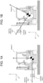
- FIG. 1 is an image diagram schematically illustrating the difference in the inertial principal axis depending on the difference in the lift height of the loading object.
- the orientation of the inertial principal axis varies between a case where the height of the lift on which the loading object is loaded is low as illustrated in FIG. 1A and a case where the height of the lift is high as illustrated in FIG. 1B .
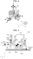
- a vehicle motion will be described using a six degree-of-freedom model for vehicles that is illustrated in FIG. 2 and expressed by the following equations (1) to (3) in order to dealing with the difference in the loading state of the loading object illustrated in FIG. 1 .
- the equation (1) is an equation that expresses the rotary motion of the vehicle
- the equation (2) is an equation that expresses the translational motion of the vehicle
- the equation (3) is an equation that expresses the attitude of a vehicle coordinate system (an x-y-z coordinate system in FIG. 2 ) relative to a ground coordinate system (x e -y e -z e coordinate system in FIG. 2 ).
- the front-rear direction (travelling direction) of the vehicle corresponds to the x-axis direction
- the lateral direction (width direction) of the vehicle corresponds to the y-axis direction
- the vertical direction corresponds to the z-axis direction.
- P, Q, and R are respective angular velocities [rad/s] for roll, pitch, and yaw
- L v , M v , and N v are respective moments [Nm] for roll, pitch, and yaw
- U, V, and W are velocities [m/s] in the respective directions of the x, y, and z-axes in the vehicle coordinate system
- ⁇ , ⁇ , and ⁇ are attitude angles [rad] of the vehicle coordinate system relative to the ground coordinate system.
- X v , Y v , and Z v are a front-rear force, lateral force, and vertical force [N] that act on the vehicle.
- J all is an inertial tensor [kg ⁇ m 2 ] constituted by the inertial principal axis and the inertial products in the respective directions of the x, y, and z-axes
- M all is a total mass [kg] obtained from adding the mass of the loading object to the mass of the vehicle.
- the inertia tensor corresponds to an example of an "inertia value" in the present invention.
- FIG. 3 illustrates outlines of respective constituent parts of a forklift (referred to as a "whole vehicle", hereinafter) 100 including the loading object, the centers of gravity of the respective constituent parts, the centers of gravity of the whole vehicle, and the coordinate origin.
- a vehicle body 102, a loading object 104, forks 106, an outer mast 108, and an inner mast 110 are assumed as the constituent parts of the forklift.
- the constituent parts of the forklift also includes an IMU (Inertial Measurement Unit) 112, but the IMU 112 is regarded as being very light and having no influence on the center of gravity of the whole vehicle 100.
- IMU Inertial Measurement Unit
- FIG. 3 a mark indicating the center of gravity is illustrated at a position of the center-of-gravity of each constituent part, and the position of the center of gravity of each constituent part is represented by a reference character in which "A" is added to the tail end of the reference character for the constituent part.
- the size of a circle of the mark indicating the positions of the centers of gravity schematically expresses the magnitude of the weight of each constituent part.
- an index j represents a variable that specifies each constituent part
- N represents the total number of constituent parts
- m j represents the weight of a constituent part j.
- ⁇ x j x j ⁇ x all
- ⁇ y j y j ⁇ y all
- ⁇ z j z j ⁇ z all
- the respective accelerations (P, Q, and R) for roll, pitch, and yaw and the front-rear acceleration and lateral acceleration of the center of gravity CG all of the whole vehicle 100 are measured by the IMU 112, and a yaw moment N v is obtained by the detection of a tire front-rear force and a tire lateral force.
- P in the equations, " ⁇ (dot)" is above "P”; the same goes for Q and R described below
- Q, and R in the equation (1) are calculated by the approximate differentiation, or the like of P, Q, and R measured at each sampling timing. In this case, only the wheel load is an unknown parameter in the equation (1).
- the roll moment L v and the pitch moment M v in the equation (1) are expressed as the sum of a moment acting on the vehicle by the tire lateral force and the tire front-rear force and a moment by the reaction force of a tire spring (vertical spring) by the following equation (6) and equation (7).
- G xall and G yall in the equation (6) and the equation (7) represent the front-rear acceleration and lateral acceleration [m/s 2 ] of the center of gravity CG all of the whole vehicle 100.
- t l and t r represent y-directional distances [m] from CG all to the right and left wheels, and If and l r represent x-directional distances [m] from CG all to the front and rear wheels.
- ⁇ FL z , ⁇ FR z , ⁇ RL z , and ⁇ RR z represent variation amounts [N] of the wheel loads on the front, rear, right, and left wheels.
- the equation (6) and the equation (7) express moments around the center of gravity CG all of the whole vehicle 100, and express a tire front-rear force sum and a lateral force sum for the respective wheels using the front-rear acceleration G xall and lateral acceleration G yall of the center of gravity CG all of the vehicle and the mass M all .
- measurement values G x , G y of the IMU 112 are converted into the acceleration at the position of the center of gravity CG all of the whole vehicle 100.
- N v ⁇ FL Fx ⁇ t l + FR Fx ⁇ t r + FL Fy + FR Fy ⁇ l f ⁇ RL Fy + RR Fy ⁇ l r
- the tire front-rear forces FL Fx , FR Fx and the tire lateral forces FL Fy , FR Fy , RL Fy , RR Fy are values converted to values in the vehicle coordinate system.
- J all , R (i) , and N v(i) do not influence the variation of each wheel load, so that J all , R (i) , and N v(i) may be any suitable value.
- Each wheel load may be estimated based on the sum of a static load of the wheel load and the variation amount of the wheel load that is calculated by the equation (9).
- J all * is expressed by the following equation (13) transformed from the equation (4).
- J all2 * is expressed by the following equation (17) transformed from the equation (4).
- the IMU 112 As illustrated in FIG. 4 , the IMU 112, a pressure sensor 114, an encoder 116, and an operation amount sensor 118 are connected to a wheel load estimation device 10 according to the first embodiment.
- the wheel load estimation device 10 is installed at any suitable position in the vehicle (forklift).
- the IMU 112 which is installed at any suitable position in the vehicle (forklift) as described above, detects the angular accelerations around the respective axes of the three axes of the vehicle coordinate system and the accelerations in the respective axis directions, and outputs detection values.
- the pressure sensor 114 is, for example, a sheet-shaped sensor provided on the whole surface of a loading surface of each fork 106 on which the loading object 104 is loaded.
- the pressure sensor 114 detects pressures that are applied to positions on the loading surface, and outputs detection values.
- the encoder 116 detects the rotation angle of a hydraulic lifting motor for moving the inner mast 110 up and down, and outputs a detection value.
- the operation amount sensor 118 detects each of an accelerator pedal stepping amount, a brake pedal stepping amount, and a steering angle, and outputs detection values.
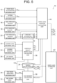
- the wheel load estimation device 10 functionally includes a front-rear acceleration obtaining unit 12, a lateral acceleration obtaining unit 14, a roll angular velocity obtaining unit 16, a pitch angular velocity obtaining unit 18, and a yaw angular velocity obtaining unit 20.
- the wheel load estimation device 10 also includes a loading load obtaining unit 22, a loading position obtaining unit 24, a lift height obtaining unit 26, a tire front-rear force obtaining unit 28, and a tire lateral force obtaining unit 30.
- the wheel load estimation device 10 also includes an angular acceleration calculation unit 32, a vehicle specification DB (Database) 34, a center-of-gravity inertia value calculation unit 36, a yaw moment calculation unit 38, a wheel load variation calculation unit 40, and a wheel load estimation unit 42.
- the front-rear acceleration obtaining unit 12, the lateral acceleration obtaining unit 14, the roll angular velocity obtaining unit 16, the pitch angular velocity obtaining unit 18, the yaw angular velocity obtaining unit 20, the loading load obtaining unit 22, the loading position obtaining unit 24, the lift height obtaining unit 26, the tire front-rear force obtaining unit 28, the tire lateral force obtaining unit 30, and the angular acceleration calculation unit 32 constitute the obtaining unit in the present disclosure.
- the front-rear acceleration obtaining unit 12 receives the detection values output from the IMU 112, and obtains, from the detection values, the acceleration G x in the x-axis direction as the front-rear acceleration G xall of the center of gravity CG all of the whole vehicle 100.
- the lateral acceleration obtaining unit 14 receives the detection values output from the IMU 112, and obtains, from the detection values, the acceleration G y in the y-axis direction as the lateral acceleration G yall of the center of gravity CG all of the whole vehicle 100.
- the roll angular velocity obtaining unit 16 receives the detection values output from the IMU 112, and obtains, from the detection values, the angular velocity around the x-axis as a roll angular velocity P.
- the pitch angular velocity obtaining unit 18 receives the detection values output from the IMU 112, and obtains, from the detection values, the angular velocity around the y-axis as a pitch angular velocity Q.
- the yaw angular velocity obtaining unit 20 receives the detection values output from the IMU 112, and obtains, from the detection values, the angular velocity around the z-axis as a yaw angular velocity R.
- the loading load obtaining unit 22 receives the detection values output from the pressure sensor 114, and obtains the weight M ⁇ of the loading object 104 loaded on the forks 106 by converting the detection values indicating the pressure into the weight.
- the loading position obtaining unit 24 receives the detection values output from the pressure sensor 114, and obtains a position where the highest detection value is detected on the loading surfaces of the forks 106, as the position of the loading object 104 loaded on the forks 106.
- the lift height obtaining unit 26 receives the detection value output from the encoder 116, calculates the height of the forks 106 with respect to a reference position (for example, the lowest portion) using the rotation angle of the hydraulic lifting motor indicated by the detection value, and obtains this height as the lift height.
- the tire front-rear force obtaining unit 28 receives the detection values output from the operation amount sensor 118, and obtains the tire front-rear forces FL Fx , FR Fx by inputting each of a breaking/driving force based on the accelerator pedal stepping amount and breaking pedal stepping amount indicated by the detection values and the steering angle, to a tire characteristic model defined in advance.
- the tire lateral force obtaining unit 30 receives the detection values output from the operation amount sensor 118, and obtains the tire lateral forces FL Fy , FR Fy , RL Fy , RR Fy by inputting the breaking/driving force based on the accelerator pedal stepping amount and breaking pedal stepping amount indicated by the detection values, the steering angle, the vehicle speed, the yaw rate, and the like, to tire characteristics defined in advance.
- the angular acceleration calculation unit 32 calculates each of a roll angular acceleration P, a pitch angular acceleration Q, and a yaw angular acceleration R by performing the approximate differentiation, or the like of the roll angular velocity P, the pitch angular velocity Q, and the yaw angular velocity R that are respectively obtained by the roll angular velocity obtaining unit 16, the pitch angular velocity obtaining unit 18, and the yaw angular velocity obtaining unit 20 at each sampling timing.
- the vehicle specification DB 34 stores a variety of data relevant to the vehicle. Specifically, information including the arrangement of the respective wheels and structures having the roll center h R , a weight M ⁇ , static loads FL z0 , FR z0 , RL z0 , RR z0 on the respective wheels, the shapes of the respective constituent parts, a weight m j , or the like, is stored.
- the center-of-gravity inertia value calculation unit 36 calculates the weight M all of the whole vehicle 100 including the loading object 104 by adding the weight M ⁇ of the loading object 104 obtained by the loading load obtaining unit 22 to the weight M ⁇ of the vehicle that is stored in the vehicle specification DB 34. Further, the center-of-gravity inertia value calculation unit 36 calculates the position 104A of the center of gravity of the loading object based on the information obtained by each of the loading load obtaining unit 22, the loading position obtaining unit 24, and the lift height obtaining unit 26. As the calculation method of the position 104A of the center of gravity of the loading object, for example, a method described in Japanese Patent Application Publication No. 2020-093741 may be employed.
- the center-of-gravity inertia value calculation unit 36 calculates the position 100A of the center of gravity CG all of the whole vehicle 100 and the positions 102A, 106A, 108A, 110A of the centers of gravity of the constituent parts j based on the position 104A of the center of gravity of the loading object and the structures of the respective constituent parts stored in the vehicle specification DB 34.
- the center-of-gravity inertia value calculation unit 36 calculates the differences ( ⁇ x j , ⁇ y j , and ⁇ z j ) in the respective axis directions between the position 100A of the center of gravity CG all of the whole vehicle 100 and the positions 102A, 104A, 106A, 108A, 110A of the centers of gravity of the constituent parts j. Further, by the equation (4), the center-of-gravity inertia value calculation unit 36 calculates the inertial tensor J all using the calculated ⁇ x j , ⁇ y j , and ⁇ z j and the weights m j of the constituent parts j stored in the vehicle specification DB 34.
- the center-of-gravity inertia value calculation unit 36 determines the z-axis directional position (z all ) of the calculated position 100A of the center of gravity CG all of the whole vehicle 100 as h CG .
- the center-of-gravity inertia value calculation unit 36 calculates the information (M all , the position 100A of CG all , the positions 102A, 106A, 108A, 110A of the centers of gravity of the constituent parts j, the position 104A of the center of gravity of the loading object, the differences ( ⁇ x j , ⁇ y j , and ⁇ z j ) in the respective axis directions between the position 100A of the center of gravity CG all of the whole vehicle 100 and the positions 102A, 104A, 106A, 108A, 110A of the centers of gravity of the constituent parts j, and h CG ) relevant to the center of gravity, and calculates the inertia tensor J all that represents the inertia value including the inertial principal axis around the center of gravity of the rigid body.
- the yaw moment calculation unit 38 calculates the respective y-directional distances t l and t r from CG all to the right and left wheels and the respective x-directional distances If and l r from CG all to the front and rear wheels based on the position 100A of the center of gravity CG all of the whole vehicle 100 calculated by the center-of-gravity inertia value calculation unit 36 and the information about the arrangement of the respective wheels stored in the vehicle specification DB 34.
- the yaw moment calculation unit 38 calculates the yaw moment N v around the center of gravity CG all of the whole vehicle 100 using the calculated ti, t r , If, and l r , the tire front-rear forces FL Fx , FR Fx obtained by the tire front-rear force obtaining unit 28, and the tire lateral forces FL Fy , FR Fy , RL Fy , RR Fy obtained by the tire lateral force obtaining unit 30.
- the wheel load variation calculation unit 40 calculates the z-directional distance h R_CG between CG all and the roll center h R from h CG calculated by the center-of-gravity inertia value calculation unit 36 and the roll center h R stored in the vehicle specification DB 34.
- the wheel load variation calculation unit 40 calculates the variation amounts ⁇ FL z , ⁇ FR z , ⁇ RL z , and ⁇ RR z of the respective wheel loads using the front-rear acceleration G xall obtained by the front-rear acceleration obtaining unit 12, the lateral acceleration G yall obtained by the lateral acceleration obtaining unit 14, the roll angular velocity P obtained by the roll angular velocity obtaining unit 16, the pitch angular velocity Q obtained by the pitch angular velocity obtaining unit 18, the yaw angular velocity R obtained by the yaw angular velocity obtaining unit 20, the roll angular acceleration P, the pitch angular acceleration Q, and the yaw angular acceleration R calculated by the angular acceleration calculation unit 32, the weight M all of the whole vehicle 100 calculated by the center-of-gravity inertia value calculation unit 36, the inertia tensor J all , the z-directional position hcc of CG all , the calculated
- the wheel load estimation unit 42 estimates the respective wheel loads FL z , FR z , RL z , and RR z from the sum of the variation amounts ⁇ FL z , ⁇ FR z , ⁇ RL z , and ⁇ RR z of the respective wheel loads calculated by the wheel load variation calculation unit 40 and the static loads FL z0 , FR z0 , RL z0 , RR z0 on the respective wheels stored in the vehicle specification DB 34, and outputs an estimation result.
- FIG. 6 is a block diagram illustrating the hardware configuration of the wheel load estimation device 10 according to the first embodiment.
- the wheel load estimation device 10 includes a CPU (Central Processing Unit) 52, a memory 54, a storage device 56, an input device 58, an output device 60, a storage medium reader 62, and a communication I/F (Interface) 64.
- the respective constituent parts are connected through a bus 66 in a mutually communicable manner.
- the storage device 56 stores a wheel load estimation program for executing a wheel load estimation process.
- the CPU 52 which is a central arithmetic processing unit, executes a variety of programs and controls the respective constituent parts. That is, the CPU 52 reads programs from the storage device 56 and executes programs using the memory 54 as a working area. The CPU 52 performs the control of the above respective constituent parts and a variety of arithmetic processes in accordance with the programs stored in the storage device 56.
- the memory 54 is constituted by a RAM (Random Access Memory) and temporarily stores programs and data as a working area.
- the storage device 56 is constituted by a ROM (Read Only Memory), an HDD (Hard Disk Drive), an SSD (Solid State Drive), and the like, and contains a variety of data and a variety of programs including an operating system.
- the input device 58 is a device such as a keyboard or a mouse for inputting a variety of information.
- the output device 60 is a device such as a display or a printer for outputting a variety of information.
- the output device 60 may function as the input device 58 by employing a touch panel display.
- the storage medium reader 62 reads data stored in a variety of storage media such as a CD (Compact Disc)-ROM, a DVD (Digital Versatile Disc)-ROM, a Blu-ray disc, or a USB (Universal Serial Bus) memory, the writing of data to such a storage media, and the like.
- the communication I/F 64 is an interface for communicating with other apparatuses.
- a standard such as Ethernet (registered trademark), FDDI or Wi-Fi (registered trademark) is used for the communication I/F 64.
- the wheel load estimation device 10 executes the wheel load estimation process illustrated in FIG. 7 .
- Step S10 the loading load obtaining unit 22 obtains the weight M ⁇ of the loading object 104 loaded on the forks 106 from the detection values of the pressure sensor 114, the loading position obtaining unit 24 obtains the position of the loading object 104 from the detection values of the pressure sensor 114, and the lift height obtaining unit 26 obtains the lift height from the detection value of the encoder 116.
- Step S12 the center-of-gravity inertia value calculation unit 36 calculates the weight M all of the whole vehicle 100, the position 100A of the center of gravity CG all , and the positions 102A, 104A, 106A, 108A, 110A of the centers of gravity of the constituent parts j based on the information obtained in the above Step S10 and the information stored in the vehicle specification DB 34, and calculates the inertia tensor J all by the equation (4).
- Step S14 the tire front-rear force obtaining unit 28 obtains the tire front-rear forces FL Fx , FR Fx and the tire lateral force obtaining unit 30 obtains the tire lateral forces FL Fy , FR Fy , RL Fy , RR Fy , based on the detection values of the operation amount sensor 118 and the tire characteristic model defined in advance.
- Step S16 the front-rear acceleration obtaining unit 12, the lateral acceleration obtaining unit 14, the roll angular velocity obtaining unit 16, the pitch angular velocity obtaining unit 18, and the yaw angular velocity obtaining unit 20 respectively obtain the front-rear acceleration G xall , the lateral acceleration G yall , the roll angular velocity P, the pitch angular velocity Q, and the yaw angular velocity R, from the detection values of the IMU 112.
- Step S18 the angular acceleration calculation unit 32 calculates each of the roll angular acceleration P, the pitch angular acceleration Q, and the yaw angular acceleration R, by performing the approximate differentiation, or the like of each of the roll angular velocity P, the pitch angular velocity Q, and the yaw angular velocity R obtained in the above-described Step S16.
- Step S20 the yaw moment calculation unit 38 calculates the respective y-directional distances t l and t r from CG all to the right and left wheels and the respective x-directional distances If and l r from CG all to the front and rear wheels. Then, by the equation (8), the yaw moment calculation unit 38 calculates the yaw moment N v using the calculated ti, t r , If, and l r and the tire front-rear forces FL Fx , FR Fx and tire lateral forces FL Fy , FR Fy , RL Fy , RR Fy obtained in the above-described Step S14.
- the wheel load variation calculation unit 40 calculates the variation amounts ⁇ FL z , ⁇ FR z , ⁇ RL z , and ⁇ RR z of the respective wheel loads using G xall , G yall , P, Q, R, P, Q, R, M all , J all , hcc, h R_CG , N v , t l , t r , l f , and l r obtained or calculated in the above-described Steps S12 to S20.
- Step S24 the wheel load estimation unit 42 estimates the respective wheel loads from the sum of the variation amounts ⁇ FL z , ⁇ FR z , ⁇ RL z , and ⁇ RR z of the respective wheel loads calculated in the above-described Step S22 and the static loads FL z0 , FR z0 , RL z0 , RR z0 on the respective wheels stored in the vehicle specification DB 34, and outputs the estimation result. Then, the process returns to Step S10. While the forklift is travelling, the processes in Steps S10 to S24 are repeatedly executed.
- the output estimation result of the wheel load is used for the control of preventing the overturn of the forklift, or the like.
- the wheel loads are accurately estimated by setting the inertial principal axis and the inertial products according to the loading state of the loading object and estimating the respective wheel loads. Further, since the wheel loads are estimated only by mounting a light sensor such as the IMU, it is not necessary to perform a general load measurement using a strain gauge, a load cell, or the like. Accordingly, the wheel loads are estimated without decreasing the rigidity of a portion of each fork, so that it is possible to avoid the risk of decreasing the rigidity of the portion of the fork.
- the yaw moment in addition to the respective wheel loads may be calculated using the constraint that the total sum of the variation amounts of the respective wheel loads is 0.
- the estimated yaw moment may be used for the control of torque vectoring.
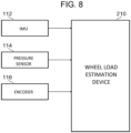
- the IMU 112, the pressure sensor 114, and the encoder 116 are connected to a wheel load estimation device 210 according to the second embodiment.
- the wheel load estimation device 210 is installed at any suitable position in the vehicle (forklift).
- the wheel load estimation device 210 functionally includes the front-rear acceleration obtaining unit 12, the lateral acceleration obtaining unit 14, the roll angular velocity obtaining unit 16, the pitch angular velocity obtaining unit 18, and the yaw angular velocity obtaining unit 20.
- the wheel load estimation device 210 also includes the loading load obtaining unit 22, the loading position obtaining unit 24, and the lift height obtaining unit 26.
- the wheel load estimation device 210 also includes the angular acceleration calculation unit 32, the vehicle specification DB 34, a center-of-gravity inertia value calculation unit 236, a wheel load variation calculation unit 240, and a wheel load estimation unit 242.
- the center-of-gravity inertia value calculation unit 236 calculates the weight M all of the whole vehicle 100 including the loading object 104, the inertia tensor J all , and the z-axis directional position h CG of the center of gravity CG all of the whole vehicle 100, similarly to the center-of-gravity inertia value calculation unit 36 in the first embodiment.
- the center-of-gravity inertia value calculation unit 236 calculates the respective y-directional distances t l and t r from CG all to the front right and front left wheels and the respective x-directional distances If and l r from CG all to the front and rear wheels, based on the position 100A of the center of gravity CG all of the whole vehicle 100 and the information about the arrangement of the respective wheels stored in the vehicle specification DB 34.
- the center-of-gravity inertia value calculation unit 236 calculates the information (M all , the position 100A of CG all , the positions 102A, 106A, 108A, 110A of the centers of gravity of the constituent parts j, the position 104A of the center of gravity of the loading object, the differences ( ⁇ x j , ⁇ y j , and ⁇ z j ) in the respective axis directions between the position 100A of the center of gravity CG all of the whole vehicle 100 and the positions 102A, 104A, 106A, 108A, 110A of the centers of gravity of the constituent parts j, h CG , the respective y-directional distances t l and t r from CG all to the front right and front left wheels, and the respective x-directional distances If and l r from CG all to the front and rear wheels) relevant to the center of gravity, and calculates the inertia tensor J all that represents the inerti
- the wheel load variation calculation unit 240 calculates the z-directional distance h R_CG between CG all and the roll center h R , similarly to the wheel load variation calculation unit 40 in the first embodiment. Then, by the equation (20), the wheel load variation calculation unit 240 calculates the variation amounts ⁇ FL z , ⁇ FR z , and ⁇ R z of the respective wheel loads and the yaw moment N v around the center of gravity CG all of the whole vehicle 100 using the front-rear acceleration G xall , the lateral acceleration G yall , the roll angular velocity P, the pitch angular velocity Q, the yaw angular velocity R, the roll angular acceleration P, the pitch angular acceleration Q, the yaw angular acceleration R, the weight M all of the whole vehicle 100, the inertia tensor J all , the z-axis directional position hcc of CG all , the calculated z-directional distance h R_CG between CG all and
- the wheel load estimation unit 242 estimates the respective wheel loads FL z , FR z and R z , from the sum of the variation amounts ⁇ FL z , ⁇ FR z , and ⁇ R z of the respective wheel loads calculated by the wheel load variation calculation unit 240 and the static loads FL z0 , FR z0 , and R z0 on the respective wheels stored in the vehicle specification DB 34. Then, the wheel load estimation unit 242 outputs the respective estimated wheel loads and the yaw moment N v calculated by the wheel load variation calculation unit 240 as estimation results.
- the hardware configuration of the wheel load estimation device 210 according to the second embodiment is the same as the hardware configuration of the wheel load estimation device 10 according to the first embodiment illustrated in FIG. 6 , and therefore descriptions are omitted.
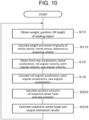
- a wheel load estimation process illustrated in FIG. 10 is executed in the wheel load estimation device 210.
- the same processes as those of the wheel load estimation process in the first embodiment are denoted by the same step reference numerals, and detailed descriptions are omitted.
- the center-of-gravity inertia value calculation unit 236 calculates the weight M all of the whole vehicle 100 including the loading object 104, the inertia tensor J all , the y-axis directional position h CG of the center of gravity CG all of the whole vehicle 100, the respective y-directional distances t l and t r from CG all to the front right and front left wheels, and the respective x-directional distances l f and l r from CG all to the front and rear wheels.
- the wheel load variation calculation unit 240 calculates the variation amounts ⁇ FL z , ⁇ FR z , and ⁇ R z of the respective wheel loads and the yaw moment N v using G xall , G yall , P, Q, R, P, Q, R, M all , J all , hcc, h R_CG , t l , t r , l f , l r obtained or calculated in the above-described Steps S212 to S18.
- Step S224 the wheel load estimation unit 242 estimates the respective wheel loads from the sum of the variation amounts ⁇ FL z , ⁇ FR z , and ⁇ R z of the respective wheel loads calculated in the above-described Step S222 and the static loads FL z0 , FR z0 , and R z0 , and outputs the respective wheel loads as estimation results, together with the yaw moment N v calculated in the above-described Step S222. Then, the process returns to Step S10. While the forklift is travelling, the processes in Steps S10 to S224 are repeatedly executed. Similarly to the first embodiment, the output estimation result of the wheel loads is used for the control of preventing the overturn of the forklift, or the like, and the output yaw moment is used for the control of torque vectoring, or the like.
- the wheel load estimation device provides the same advantageous effects as those in the first embodiment, also for the three-wheel forklift.
- the tire front-rear force obtaining unit 28, the tire lateral force obtaining unit 30, and the yaw moment calculation unit 38 may be provided in order to calculate the yaw moment.
- the variation amounts of the respective wheel loads may be calculated using the equation (18).
- the tire front-rear force obtaining unit 28, the tire lateral force obtaining unit 30, and the yaw moment calculation unit 38 may be excluded, and in the wheel load variation calculation unit 40, the yaw moment may be calculated together with the variation amounts of the respective wheel loads using the equation (12) under the constraint of the equation (11), which expresses that the total sum of the variation amounts of the wheel loads about the respective wheels is 0.
- the forks may have a wire, and the lift height may be obtained by measuring the change in the length of the wire at the time of lifting.
- the other values to be obtained by the respective obtaining units are also not limited to the case where the other values are obtained by the methods described in the above-described embodiments, and may be obtained by other methods.
- the wheel load estimation device may be configured as an external device.
- the forklift include a communication unit that sends, to the wheel load estimation device, the respective detection values of the IMU 112, the pressure sensor 114, the encoder 116, and the operation amount sensor 118, and the wheel load estimation device configured as the external device may obtain a variety of information sent from the communication unit of the forklift, and may estimate the wheel loads by the same process as those in the above embodiments.
- the present invention may be applied to any vehicle that travels while the loading object is loaded in various states, for example, to a truck, or the like.
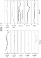
- FIG. 11 shows an example of the wheel load estimation result in the case where a three-wheel forklift travels forward and turns right.
- estimation values of the respective wheel loads estimated by the equation (20) are compared with measurement values obtained by actually measuring the wheel loads. As shown in FIG. 11 , the estimation values roughly coincide with the measurement values of the wheel loads. This means that the wheel loads are accurately estimated.
- FIG. 12 shows a result of estimating the respective wheel loads by the equation (20) in the case where the three-wheel forklift having a load of 800 kg and a lift height of 1.5 m travels at the time of rearward braking operation.
- FIG. 12A shows a case where the inertia tensor J all is set at a lift height of 0.2 m without considering the actual lift height
- FIG. 12B shows a case where the inertia tensor J all is set at a lift height of 1.5 m, which is the same as the actual lift height.
- FIG. 12 shows a result of estimating the respective wheel loads by the equation (20) in the case where the three-wheel forklift having a load of 800 kg and a lift height of 1.5 m travels at the time of rearward braking operation.
- FIG. 12A shows a case where the inertia tensor J all is set at a lift height of 0.2 m without considering the actual lift height
- FIG. 12B shows a
- FIG. 13 a comparison of estimation results of the wheel load based on whether or not the inertial products are considered when the forklift travels as in FIG. 12 will be described.
- FIG. 13A shows a case where there is no inertial product element
- FIG. 13B shows a case where there are inertial product elements.
- the lift height at the time of the calculation of the inertia tensor J all is 1.5 m, and only the influence of the setting of the inertial product elements is considered in the comparison.
- the estimation error of the wheel load is reduced.
- the off-diagonal elements of the inertia tensor J all may be 0 in the above-described embodiments.
- the wheel load estimation process that the CPU executes after reading software (program) in the above-described embodiments may be executed by a variety of processors other than the CPU.
- the processors in this case include a PLD (Programmable Logic Device) in which the circuit configuration is changeable after the production, as exemplified by an FPGA (Field-Programmable Gate Array), and a dedicated electric circuit that is a processor having a circuit configuration specially designed for executing a specified process, as exemplified by an ASIC (Application Specific Integrated Circuit).
- the wheel load estimation process may be executed by one of the variety of processors, or may be executed by a combination (for example, a combination of a plurality of FPGAs, a combination of a CPU and an FPGA, or the like) of two or more processors of the same kind or different kinds.
- the hardware structure of the variety of processors is an electric circuit in which circuit elements such as semiconductor elements are combined.
- the wheel load estimation program is stored (installed) in the storage device in advance, but the present invention is not limited to this aspect.
- the program may be stored in a storage medium such as a CD-ROM, a DVD-ROM, a Blu-ray disc, and a USB memory.
- the program may be also downloaded from an external device through a network.
Landscapes
- Engineering & Computer Science (AREA)
- Mechanical Engineering (AREA)
- Transportation (AREA)
- Structural Engineering (AREA)
- Geology (AREA)
- Life Sciences & Earth Sciences (AREA)
- Physics & Mathematics (AREA)
- Automation & Control Theory (AREA)
- Mathematical Physics (AREA)
- Civil Engineering (AREA)
- Chemical & Material Sciences (AREA)
- Combustion & Propulsion (AREA)
- General Physics & Mathematics (AREA)
- Control Of Driving Devices And Active Controlling Of Vehicle (AREA)
- Forklifts And Lifting Vehicles (AREA)
- Steering Control In Accordance With Driving Conditions (AREA)
- Regulating Braking Force (AREA)
- Arrangements For Transmission Of Measured Signals (AREA)
Abstract
Description
- The present invention relates to a wheel load estimation device and a wheel load estimation program.
- Conventionally, in a vehicle such as a forklift that lifts a loading object and travels, it has estimated the load on each wheel supporting the vehicle for avoiding the danger of wheel rise, vehicle overturn, and the like due to the deviation of the center of gravity of the vehicle.
- For example, there has been proposed a technique in which front-rear and lateral accelerations, a roll angular velocity, and a pitch angular velocity are measured in four-wheel vehicles (see Patent Document 1). In this technique, the load on each wheel is estimated based on a pitch moment for which a vertical rigidity of each wheel, a front-rear directional behavior of the vehicle, the inclination of a roll inertial principal axis, and a gyro effect are considered, and a roll moment for which a lateral directional behavior of the vehicle is considered.
- Further, for example, there has been proposed a technique in which front-rear and lateral accelerations, a roll angular velocity, and a pitch angular velocity are measured in four-wheel vehicles (see Patent Document 2). In this technique, the load on each wheel is estimated based on a pitch moment by a front-rear directional behavior of the vehicle, a roll moment by a lateral directional behavior of the vehicle, and a pitch inertia and roll inertia of the vehicle.
- Further, for example, there has been proposed a technique in which the load on each wheel and the wheel speed of two driving wheels are measured in forklifts (see Patent Document 3). In this technique, the wheel speed is used for the calculation of a turning radius, and a steering amount and a braking/driving torque are adjusted depending on the decrease in measurement value of wheel load on each wheel.
-
- Patent Document 1:
Japanese Patent Application Publication No. 2004-058960 - Patent Document 2:
Japanese Patent Application Publication No. 2013-216278 - Patent Document 3:
Japanese Patent Application Publication No. 2001-063991 - However, the techniques described in
Patent Documents 1 and 2 are intended for use in general four-wheel vehicles, and travelling situation while a loading object having a heavy weight is loaded in various states as in the case of forklifts, for example, is not considered. For that reason, there is a problem that the wheel load of a vehicle that travels while a loading object having a heavy weight is loaded in various states is not estimated appropriately by the techniques described inPatent Documents 1 and 2. - In the technique described in
Patent Document 3, the strain of a portion on which the loading object is loaded is used for measuring the wheel load. However, it is necessary to decrease the rigidity of the portion on which the loading object is loaded for obtaining the strain, and there is a problem that of occurrence of safety risk. - The present invention, which has been made in view of the above circumstance, is to provide a wheel load estimation device and program that accurately estimate a wheel load without decreasing a rigidity of a rigid body even in a case where a center of gravity of the rigid body fluctuates.
- In order to solve the above object, a wheel load estimation device according to the present invention includes an obtaining unit obtaining angular velocities and angular accelerations of a rigid body around three axes of the rigid body including an element, accelerations of the rigid body in a front-rear direction being a traveling direction of the rigid body and in a lateral direction being a width direction of the rigid body, a weight of the element, and a position including a height of the element, the element fluctuating a center of gravity of the rigid body, a center-of-gravity inertia value calculation unit calculating information relevant to the center of gravity of the rigid body and an inertia value including an inertial principal axis around the center of gravity of the rigid body, a wheel load variation calculation unit calculating variation amounts of wheel loads that each act on a corresponding one of a plurality of wheels supporting the rigid body based on the angular velocities, the angular accelerations, and the accelerations in the front-rear direction and the lateral direction obtained by the obtaining unit, and the information relevant to the center of gravity of the rigid body and the inertia value calculated by the center-of-gravity inertia value calculation unit, and a wheel load estimation unit estimating the wheel loads based on the variation amounts of the wheel loads calculated by the wheel load variation calculation unit and static loads that act on the respective wheels.
- With the wheel load estimation device according to the present invention, the obtaining unit obtains the angular velocities and angular accelerations of the rigid body around the three axes of the rigid body including the element that fluctuates the center of gravity of the rigid body, the accelerations in the front-rear direction being the traveling direction of the rigid body and the lateral direction being the width direction of the rigid body, the weight of element, and the position including the height of the element. The center-of-gravity inertia value calculation unit calculates the information relevant to the center of gravity of the rigid body, and calculates the inertia value including the inertial principal axis around the center of gravity of the rigid body. The wheel load variation amount calculation unit calculates the variation amounts of the wheel loads that each act on the corresponding one of the plurality of wheels supporting the rigid body based on the angular velocities, the angular accelerations, the accelerations in the front-rear direction and the lateral direction obtained by the obtaining unit, and the information relevant to the center of gravity of the rigid body and the inertia value calculated by the center-of-gravity inertia value calculation unit. The wheel load estimation unit estimates the wheel loads based on the variation amounts of the wheel loads calculated by the wheel load variation calculation unit, and the static loads that act on the respective wheels. Thus, it is possible to accurately estimate the wheel load without decreasing the rigidity of the rigid body even in the case where the center of gravity of the rigid body fluctuates.
- The center-of-gravity inertia value calculation unit calculates a position of the center of gravity of the rigid body including the element and respective positions of centers of gravity of a plurality of constituent parts constituting the rigid body based on the weight and the position of the element obtained by the obtaining unit and respective structures of the constituent parts, and calculates the inertia value using differences between the position of the center-of-gravity of the rigid body including the element and the respective positions of the centers of gravity of the constituent parts.
- The center-of-gravity inertia value calculation unit may calculate the inertia value further including inertial products. Thus, the inertia value depending on the fluctuation of the center of gravity is more appropriately calculated, and it is possible to more accurately estimate the wheel load.
- The obtaining unit obtains lateral forces and front-rear forces that act on the wheels, and the wheel load variation calculation unit calculates the variation amounts of the wheel loads further using a yaw moment around the center of gravity of the rigid body, the yaw moment being calculated based on the lateral forces and the front-rear forces obtained by the obtaining unit. Thus, it is possible to estimate the wheel load in consideration of the yaw moment around the center of gravity of the rigid body.
- The wheel load variation calculation unit may calculate a yaw moment around the center of gravity of the rigid body together with the variation amounts of the wheel loads under the constraint that the total sum of the respective variation amounts of the wheel loads on the plurality of wheels is 0. Thus, it is possible to calculate the yaw moment together with the wheel load based on the information obtained by the obtaining unit.
- The rigid body may be a vehicle, and the element fluctuating the center of gravity may be a loading object that is loaded on the vehicle. Further, the vehicle may be a forklift, and the loading object may be loaded on forks being operable vertically. Thus, it is possible to accurately estimate the wheel load for a vehicle that travels while the loading object is loaded in various states, as exemplified by a forklift.
- The information relevant to the center of gravity of the rigid body may include a distance in a vertical direction between the position of the center of gravity of the rigid body and a roll center of the rigid body, a position of the center of gravity of the rigid body in the lateral direction, and respective distances in the lateral direction between the plurality of wheels and the position of the center of gravity of the rigid body.
- A wheel load estimation program according to the present invention is a program for causing a computer to function as the units of the above-described wheel load estimation device.
- With the wheel load estimation device and program in the present invention, it is possible to accurately estimate the wheel load without decreasing the rigidity of the rigid body even in the case where the center of gravity of the rigid body fluctuates.
-
-
FIG. 1 is an image diagram schematically illustrating a difference in an inertial principal axis depending on a difference in a lift height of a loading object. -
FIG. 2 is a diagram for explaining a vehicle coordinate system relative to a ground coordinate system. -
FIG. 3 is a diagram illustrating outlines of constituent elements of a whole vehicle, centers of gravity, and a coordinate origin. -
FIG. 4 is a block diagram illustrating a wheel load estimation device according to a first embodiment and respective constituent parts that are connected to the wheel load estimation device. -
FIG. 5 is a functional block diagram of the wheel load estimation device according to the first embodiment. -
FIG. 6 is a block diagram illustrating a hardware configuration of the wheel load estimation device. -
FIG. 7 is a flowchart illustrating an example of a wheel load estimation process in the first embodiment. -
FIG. 8 is a block diagram illustrating a wheel load estimation device according to a second embodiment and respective constituent parts that are connected to the wheel load estimation device. -
FIG. 9 is a functional block diagram of the wheel load estimation device according to the second embodiment. -
FIG. 10 is a flowchart illustrating an example of a wheel load estimation process in the second embodiment. -
FIG. 11 is a diagram showing an example of a wheel load estimation result. -
FIG. 12 is a diagram for explaining an effect of changing an inertia value depending on a lift height. -
FIG. 13 is a diagram for explaining a comparison of wheel load estimation results based on whether inertial products are considered. - The following will describe embodiments according to the present invention with reference to the drawings.
- Firstly, a principle of a first embodiment will be described. In the first embodiment, estimation of the load on each wheel in a forklift that includes four wheels as front, rear, right, and left wheels and that travels while a loading object is loaded on forks being operatable vertically will be described. The forklift serves as an example of a rigid body including an element that fluctuates the center of gravity. Further, in the first embodiment, it is premised that a vehicle behavior including the front-rear acceleration, lateral acceleration, roll angular velocity, pitch angular velocity, and yaw angular velocity of the forklift is measured. In the first embodiment, it is also premised that the weight of the loading object, the lift height, and the loading position of the loading object with respect to the forks may be detected.
- Unlike passenger cars, the forklift travels in states where the loading object having a heavy weight is lifted at various lift heights. The loading object is sometimes located in a located position shifted from the position of the center-of-gravity of the forklift in a y-direction (lateral direction of the forklift). Depending on the loading state of the loading object, the orientation of an inertial principal axis changes with respect to the rotation axes for roll, pitch, and yaw. Hence, in the first embodiment, the inertial principal axis and inertial products are set depending on the loading state of the loading object.
FIG. 1 is an image diagram schematically illustrating the difference in the inertial principal axis depending on the difference in the lift height of the loading object. The orientation of the inertial principal axis varies between a case where the height of the lift on which the loading object is loaded is low as illustrated inFIG. 1A and a case where the height of the lift is high as illustrated inFIG. 1B . - A vehicle motion will be described using a six degree-of-freedom model for vehicles that is illustrated in
FIG. 2 and expressed by the following equations (1) to (3) in order to dealing with the difference in the loading state of the loading object illustrated inFIG. 1 . The equation (1) is an equation that expresses the rotary motion of the vehicle, the equation (2) is an equation that expresses the translational motion of the vehicle, and the equation (3) is an equation that expresses the attitude of a vehicle coordinate system (an x-y-z coordinate system inFIG. 2 ) relative to a ground coordinate system (xe-ye-ze coordinate system inFIG. 2 ). In the vehicle coordinate system, the front-rear direction (travelling direction) of the vehicle corresponds to the x-axis direction, the lateral direction (width direction) of the vehicle corresponds to the y-axis direction, and the vertical direction corresponds to the z-axis direction.
[Formula 1]


- In the equations (1) to (3), P, Q, and R are respective angular velocities [rad/s] for roll, pitch, and yaw, and Lv, Mv, and Nv are respective moments [Nm] for roll, pitch, and yaw. U, V, and W are velocities [m/s] in the respective directions of the x, y, and z-axes in the vehicle coordinate system, and φ, θ, and ϕ are attitude angles [rad] of the vehicle coordinate system relative to the ground coordinate system. Xv, Yv, and Zv are a front-rear force, lateral force, and vertical force [N] that act on the vehicle. Jall is an inertial tensor [kg·m2] constituted by the inertial principal axis and the inertial products in the respective directions of the x, y, and z-axes, and Mall is a total mass [kg] obtained from adding the mass of the loading object to the mass of the vehicle. The inertia tensor corresponds to an example of an "inertia value" in the present invention.
- In the first embodiment, a portion in the equation (1) that is relevant to the rotary motion of the vehicle is used. The setting of the inertia tensor Jall in the equation (1) will be described with reference to
FIG. 3. FIG. 3 illustrates outlines of respective constituent parts of a forklift (referred to as a "whole vehicle", hereinafter) 100 including the loading object, the centers of gravity of the respective constituent parts, the centers of gravity of the whole vehicle, and the coordinate origin. In the example inFIG. 3 , avehicle body 102, aloading object 104,forks 106, anouter mast 108, and aninner mast 110 are assumed as the constituent parts of the forklift. The constituent parts of the forklift also includes an IMU (Inertial Measurement Unit) 112, but theIMU 112 is regarded as being very light and having no influence on the center of gravity of thewhole vehicle 100. InFIG. 3 , a mark indicating the center of gravity is illustrated at a position of the center-of-gravity of each constituent part, and the position of the center of gravity of each constituent part is represented by a reference character in which "A" is added to the tail end of the reference character for the constituent part. The size of a circle of the mark indicating the positions of the centers of gravity schematically expresses the magnitude of the weight of each constituent part. - The configuration of the inertia tensor Jall is expressed by the following equation (4). On the right-hand side in the equation (4), diagonal elements represent an inertial principal axis, and off-diagonal elements represent inertial products.
[Formula 2]
- In the equation (4), an index j represents a variable that specifies each constituent part, N represents the total number of constituent parts, and mj represents the weight of a constituent part j. When the center of gravity of the
whole vehicle 100 is represented as CGall, the position (xall, yall, zall) of CGall is calculated using the weight of theloading object 104, the lift height, and the loading position of theloading object 104 with respect to theforks 106. In the equation (4), Δxj, Δyj, and Δzj are differences in the respective axis directions between aposition 100A of the center of gravity CGall of thewhole vehicle 100 andrespective positions
[Formula 3]
- The respective accelerations (P, Q, and R) for roll, pitch, and yaw and the front-rear acceleration and lateral acceleration of the center of gravity CGall of the
whole vehicle 100 are measured by theIMU 112, and a yaw moment Nv is obtained by the detection of a tire front-rear force and a tire lateral force. Further, P (in the equations, "· (dot)" is above "P"; the same goes for Q and R described below), Q, and R in the equation (1) are calculated by the approximate differentiation, or the like of P, Q, and R measured at each sampling timing. In this case, only the wheel load is an unknown parameter in the equation (1). - More details will be described below. The roll moment Lv and the pitch moment Mv in the equation (1) are expressed as the sum of a moment acting on the vehicle by the tire lateral force and the tire front-rear force and a moment by the reaction force of a tire spring (vertical spring) by the following equation (6) and equation (7).
[Formula 4]

- Gxall and Gyall in the equation (6) and the equation (7) represent the front-rear acceleration and lateral acceleration [m/s2] of the center of gravity CGall of the
whole vehicle 100. hR_CG represents a z-directional distance (= zall - hR) [m] between CGall and a roll center hR, and hCG represents a z-directional distance (= zall) [m] of CGall. tl and tr represent y-directional distances [m] from CGall to the right and left wheels, and If and lr represent x-directional distances [m] from CGall to the front and rear wheels. ΔFLz, ΔFRz, ΔRLz, and ΔRRz represent variation amounts [N] of the wheel loads on the front, rear, right, and left wheels. - The equation (6) and the equation (7) express moments around the center of gravity CGall of the
whole vehicle 100, and express a tire front-rear force sum and a lateral force sum for the respective wheels using the front-rear acceleration Gxall and lateral acceleration Gyall of the center of gravity CGall of the vehicle and the mass Mall. In the case where theIMU 112 is attached to any suitable position on thevehicle body 102 as illustrated inFIG. 3 , measurement values Gx, Gy of theIMU 112 are converted into the acceleration at the position of the center of gravity CGall of thewhole vehicle 100. The yaw moment Nv is expressed as the sum of moments by tire front-rear forces FLFx, FRFx of the two driving wheels and tire lateral forces FLFy, FRFy, RLFy, RRFy of the respective wheels, by the following equation (8).
[Formula 5]
- The tire front-rear forces FLFx, FRFx and the tire lateral forces FLFy, FRFy, RLFy, RRFy are values converted to values in the vehicle coordinate system. When the equation (1) is expressed using the equations (4) to (8) and the variation amounts of the respective wheel loads that are unknown parameters are obtained, the following equation (9) is satisfied.
[Formula 6]
- In the equation (9), '+' on the right shoulder of the first term on the right-hand side shows a pseudo inverse matrix, and the variation of the wheel load on the left-hand side is obtained as an approximate value. For that reason, the relation between the right-hand side and the left-hand side in the equation (9) is expressed using '≈'. Hereinafter, at the time of use of pseudo inverse matrixes, all relations between right-hand sides and left-hand sides are expressed using '≈'. An index i indicates a sampling timing. The reason why the elements on the third line are 0 is because the variation of each wheel load in the vertical direction does not contribute to a yaw rotary motion. In this regard, Jall, R(i), and Nv(i) do not influence the variation of each wheel load, so that Jall, R(i), and Nv(i) may be any suitable value. Each wheel load may be estimated based on the sum of a static load of the wheel load and the variation amount of the wheel load that is calculated by the equation (9).
- Further, as a transformation of the equation (9), the variation amount of each wheel load and the yaw moment may be estimated as unknown parameters. In this case, the equation (9) is transformed as shown in the following equation (10).
[Formula 7]
- Further, the total sum of the variation amounts of the respective wheel loads at each sampling timing i is 0, and therefore, a constraint in the following equation (11) is satisfied.
[Formula 8]
- When the constraint in the equation (11) is added to the equation (10), the following equation (12) is satisfied, and the variation amounts of the respective wheel loads and the yaw moment may be calculated using the equation (12).
[Formula 9]
- In the equation (12), Jall* is expressed by the following equation (13) transformed from the equation (4).
[Formula 10]
- Furthermore, when roll rigidity distribution ratios at, ar based on vertical rigidities kf, kr of the front and rear wheels are applied to the equation (12), the following equation (14) is satisfied.
[Formula 11]
- In the equation (14), '-1' on the right shoulder of the first term on the right-hand side shows an inverse matrix. Further, the roll rigidity distribution ratios at, ar in the equation (14) are calculated by the following equation (15) and equation (16).
[Formula 12]

- Further, in the equation (14), Jall2* is expressed by the following equation (17) transformed from the equation (4).
[Formula 13]
- The following will describe a configuration of a wheel load estimation device according to the first embodiment.
- As illustrated in
FIG. 4 , theIMU 112, apressure sensor 114, anencoder 116, and anoperation amount sensor 118 are connected to a wheelload estimation device 10 according to the first embodiment. The wheelload estimation device 10 is installed at any suitable position in the vehicle (forklift). - The
IMU 112, which is installed at any suitable position in the vehicle (forklift) as described above, detects the angular accelerations around the respective axes of the three axes of the vehicle coordinate system and the accelerations in the respective axis directions, and outputs detection values. Thepressure sensor 114 is, for example, a sheet-shaped sensor provided on the whole surface of a loading surface of eachfork 106 on which theloading object 104 is loaded. Thepressure sensor 114 detects pressures that are applied to positions on the loading surface, and outputs detection values. Theencoder 116 detects the rotation angle of a hydraulic lifting motor for moving theinner mast 110 up and down, and outputs a detection value. Theoperation amount sensor 118 detects each of an accelerator pedal stepping amount, a brake pedal stepping amount, and a steering angle, and outputs detection values. - As illustrated in
FIG. 5 , the wheelload estimation device 10 functionally includes a front-rearacceleration obtaining unit 12, a lateralacceleration obtaining unit 14, a roll angularvelocity obtaining unit 16, a pitch angularvelocity obtaining unit 18, and a yaw angularvelocity obtaining unit 20. The wheelload estimation device 10 also includes a loadingload obtaining unit 22, a loadingposition obtaining unit 24, a liftheight obtaining unit 26, a tire front-rearforce obtaining unit 28, and a tire lateralforce obtaining unit 30. The wheelload estimation device 10 also includes an angularacceleration calculation unit 32, a vehicle specification DB (Database) 34, a center-of-gravity inertiavalue calculation unit 36, a yawmoment calculation unit 38, a wheel loadvariation calculation unit 40, and a wheelload estimation unit 42. The front-rearacceleration obtaining unit 12, the lateralacceleration obtaining unit 14, the roll angularvelocity obtaining unit 16, the pitch angularvelocity obtaining unit 18, the yaw angularvelocity obtaining unit 20, the loadingload obtaining unit 22, the loadingposition obtaining unit 24, the liftheight obtaining unit 26, the tire front-rearforce obtaining unit 28, the tire lateralforce obtaining unit 30, and the angularacceleration calculation unit 32 constitute the obtaining unit in the present disclosure. - The front-rear
acceleration obtaining unit 12 receives the detection values output from theIMU 112, and obtains, from the detection values, the acceleration Gx in the x-axis direction as the front-rear acceleration Gxall of the center of gravity CGall of thewhole vehicle 100. Similarly, the lateralacceleration obtaining unit 14 receives the detection values output from theIMU 112, and obtains, from the detection values, the acceleration Gy in the y-axis direction as the lateral acceleration Gyall of the center of gravity CGall of thewhole vehicle 100. - The roll angular
velocity obtaining unit 16 receives the detection values output from theIMU 112, and obtains, from the detection values, the angular velocity around the x-axis as a roll angular velocity P. The pitch angularvelocity obtaining unit 18 receives the detection values output from theIMU 112, and obtains, from the detection values, the angular velocity around the y-axis as a pitch angular velocity Q. The yaw angularvelocity obtaining unit 20 receives the detection values output from theIMU 112, and obtains, from the detection values, the angular velocity around the z-axis as a yaw angular velocity R. - The loading
load obtaining unit 22 receives the detection values output from thepressure sensor 114, and obtains the weight Mα of theloading object 104 loaded on theforks 106 by converting the detection values indicating the pressure into the weight. The loadingposition obtaining unit 24 receives the detection values output from thepressure sensor 114, and obtains a position where the highest detection value is detected on the loading surfaces of theforks 106, as the position of theloading object 104 loaded on theforks 106. The liftheight obtaining unit 26 receives the detection value output from theencoder 116, calculates the height of theforks 106 with respect to a reference position (for example, the lowest portion) using the rotation angle of the hydraulic lifting motor indicated by the detection value, and obtains this height as the lift height. - The tire front-rear
force obtaining unit 28 receives the detection values output from theoperation amount sensor 118, and obtains the tire front-rear forces FLFx, FRFx by inputting each of a breaking/driving force based on the accelerator pedal stepping amount and breaking pedal stepping amount indicated by the detection values and the steering angle, to a tire characteristic model defined in advance. Similarly, the tire lateralforce obtaining unit 30 receives the detection values output from theoperation amount sensor 118, and obtains the tire lateral forces FLFy, FRFy, RLFy, RRFy by inputting the breaking/driving force based on the accelerator pedal stepping amount and breaking pedal stepping amount indicated by the detection values, the steering angle, the vehicle speed, the yaw rate, and the like, to tire characteristics defined in advance. - The angular
acceleration calculation unit 32 calculates each of a roll angular acceleration P, a pitch angular acceleration Q, and a yaw angular acceleration R by performing the approximate differentiation, or the like of the roll angular velocity P, the pitch angular velocity Q, and the yaw angular velocity R that are respectively obtained by the roll angularvelocity obtaining unit 16, the pitch angularvelocity obtaining unit 18, and the yaw angularvelocity obtaining unit 20 at each sampling timing. - The
vehicle specification DB 34 stores a variety of data relevant to the vehicle. Specifically, information including the arrangement of the respective wheels and structures having the roll center hR, a weight Mβ, static loads FLz0, FRz0, RLz0, RRz0 on the respective wheels, the shapes of the respective constituent parts, a weight mj, or the like, is stored. - The center-of-gravity inertia
value calculation unit 36 calculates the weight Mall of thewhole vehicle 100 including theloading object 104 by adding the weight Mα of theloading object 104 obtained by the loadingload obtaining unit 22 to the weight Mβ of the vehicle that is stored in thevehicle specification DB 34. Further, the center-of-gravity inertiavalue calculation unit 36 calculates theposition 104A of the center of gravity of the loading object based on the information obtained by each of the loadingload obtaining unit 22, the loadingposition obtaining unit 24, and the liftheight obtaining unit 26. As the calculation method of theposition 104A of the center of gravity of the loading object, for example, a method described inJapanese Patent Application Publication No. 2020-093741 - Further, the center-of-gravity inertia
value calculation unit 36 calculates theposition 100A of the center of gravity CGall of thewhole vehicle 100 and thepositions position 104A of the center of gravity of the loading object and the structures of the respective constituent parts stored in thevehicle specification DB 34. Then, by the equations (5), the center-of-gravity inertiavalue calculation unit 36 calculates the differences (Δxj, Δyj, and Δzj) in the respective axis directions between theposition 100A of the center of gravity CGall of thewhole vehicle 100 and thepositions value calculation unit 36 calculates the inertial tensor Jall using the calculated Δxj, Δyj, and Δzj and the weights mj of the constituent parts j stored in thevehicle specification DB 34. - The center-of-gravity inertia
value calculation unit 36 determines the z-axis directional position (zall) of thecalculated position 100A of the center of gravity CGall of thewhole vehicle 100 as hCG. - Consequently, the center-of-gravity inertia
value calculation unit 36 calculates the information (Mall, theposition 100A of CGall, thepositions position 104A of the center of gravity of the loading object, the differences (Δxj, Δyj, and Δzj) in the respective axis directions between theposition 100A of the center of gravity CGall of thewhole vehicle 100 and thepositions - The yaw
moment calculation unit 38 calculates the respective y-directional distances tl and tr from CGall to the right and left wheels and the respective x-directional distances If and lr from CGall to the front and rear wheels based on theposition 100A of the center of gravity CGall of thewhole vehicle 100 calculated by the center-of-gravity inertiavalue calculation unit 36 and the information about the arrangement of the respective wheels stored in thevehicle specification DB 34. Then, by the equation (8), the yawmoment calculation unit 38 calculates the yaw moment Nv around the center of gravity CGall of thewhole vehicle 100 using the calculated ti, tr, If, and lr, the tire front-rear forces FLFx, FRFx obtained by the tire front-rearforce obtaining unit 28, and the tire lateral forces FLFy, FRFy, RLFy, RRFy obtained by the tire lateralforce obtaining unit 30. - The wheel load
variation calculation unit 40 calculates the z-directional distance hR_CG between CGall and the roll center hR from hCG calculated by the center-of-gravity inertiavalue calculation unit 36 and the roll center hR stored in thevehicle specification DB 34. Then, by the equation (9), the wheel loadvariation calculation unit 40 calculates the variation amounts ΔFLz, ΔFRz, ΔRLz, and ΔRRz of the respective wheel loads using the front-rear acceleration Gxall obtained by the front-rearacceleration obtaining unit 12, the lateral acceleration Gyall obtained by the lateralacceleration obtaining unit 14, the roll angular velocity P obtained by the roll angularvelocity obtaining unit 16, the pitch angular velocity Q obtained by the pitch angularvelocity obtaining unit 18, the yaw angular velocity R obtained by the yaw angularvelocity obtaining unit 20, the roll angular acceleration P, the pitch angular acceleration Q, and the yaw angular acceleration R calculated by the angularacceleration calculation unit 32, the weight Mall of thewhole vehicle 100 calculated by the center-of-gravity inertiavalue calculation unit 36, the inertia tensor Jall, the z-directional position hcc of CGall, the calculated z-directional distance hR_CG between CGall and the roll center hR, the yaw moment Nv calculated by the yawmoment calculation unit 38, and the x or y-directional distances ti, tr, If, lr from CGall to the respective wheels. - The wheel
load estimation unit 42 estimates the respective wheel loads FLz, FRz, RLz, and RRz from the sum of the variation amounts ΔFLz, ΔFRz, ΔRLz, and ΔRRz of the respective wheel loads calculated by the wheel loadvariation calculation unit 40 and the static loads FLz0, FRz0, RLz0, RRz0 on the respective wheels stored in thevehicle specification DB 34, and outputs an estimation result. -
FIG. 6 is a block diagram illustrating the hardware configuration of the wheelload estimation device 10 according to the first embodiment. As illustrated inFIG. 6 , the wheelload estimation device 10 includes a CPU (Central Processing Unit) 52, amemory 54, astorage device 56, aninput device 58, anoutput device 60, astorage medium reader 62, and a communication I/F (Interface) 64. The respective constituent parts are connected through abus 66 in a mutually communicable manner. - The
storage device 56 stores a wheel load estimation program for executing a wheel load estimation process. TheCPU 52, which is a central arithmetic processing unit, executes a variety of programs and controls the respective constituent parts. That is, theCPU 52 reads programs from thestorage device 56 and executes programs using thememory 54 as a working area. TheCPU 52 performs the control of the above respective constituent parts and a variety of arithmetic processes in accordance with the programs stored in thestorage device 56. - The
memory 54 is constituted by a RAM (Random Access Memory) and temporarily stores programs and data as a working area. Thestorage device 56 is constituted by a ROM (Read Only Memory), an HDD (Hard Disk Drive), an SSD (Solid State Drive), and the like, and contains a variety of data and a variety of programs including an operating system. - The
input device 58 is a device such as a keyboard or a mouse for inputting a variety of information. Theoutput device 60 is a device such as a display or a printer for outputting a variety of information. Theoutput device 60 may function as theinput device 58 by employing a touch panel display. Thestorage medium reader 62 reads data stored in a variety of storage media such as a CD (Compact Disc)-ROM, a DVD (Digital Versatile Disc)-ROM, a Blu-ray disc, or a USB (Universal Serial Bus) memory, the writing of data to such a storage media, and the like. - The communication I/
F 64 is an interface for communicating with other apparatuses. For example, a standard such as Ethernet (registered trademark), FDDI or Wi-Fi (registered trademark) is used for the communication I/F 64. - The following will describe an operation of the wheel
load estimation device 10 according to the first embodiment. When the forklift starts to travel, the wheelload estimation device 10 executes the wheel load estimation process illustrated inFIG. 7 . - In Step S10, the loading
load obtaining unit 22 obtains the weight Mα of theloading object 104 loaded on theforks 106 from the detection values of thepressure sensor 114, the loadingposition obtaining unit 24 obtains the position of theloading object 104 from the detection values of thepressure sensor 114, and the liftheight obtaining unit 26 obtains the lift height from the detection value of theencoder 116. - Next, in Step S12, the center-of-gravity inertia
value calculation unit 36 calculates the weight Mall of thewhole vehicle 100, theposition 100A of the center of gravity CGall, and thepositions vehicle specification DB 34, and calculates the inertia tensor Jall by the equation (4). - Next, in Step S14, the tire front-rear
force obtaining unit 28 obtains the tire front-rear forces FLFx, FRFx and the tire lateralforce obtaining unit 30 obtains the tire lateral forces FLFy, FRFy, RLFy, RRFy, based on the detection values of theoperation amount sensor 118 and the tire characteristic model defined in advance. - Next, in Step S16, the front-rear
acceleration obtaining unit 12, the lateralacceleration obtaining unit 14, the roll angularvelocity obtaining unit 16, the pitch angularvelocity obtaining unit 18, and the yaw angularvelocity obtaining unit 20 respectively obtain the front-rear acceleration Gxall, the lateral acceleration Gyall, the roll angular velocity P, the pitch angular velocity Q, and the yaw angular velocity R, from the detection values of theIMU 112. - Next, in Step S18, the angular
acceleration calculation unit 32 calculates each of the roll angular acceleration P, the pitch angular acceleration Q, and the yaw angular acceleration R, by performing the approximate differentiation, or the like of each of the roll angular velocity P, the pitch angular velocity Q, and the yaw angular velocity R obtained in the above-described Step S16. - Next, in Step S20, the yaw
moment calculation unit 38 calculates the respective y-directional distances tl and tr from CGall to the right and left wheels and the respective x-directional distances If and lr from CGall to the front and rear wheels. Then, by the equation (8), the yawmoment calculation unit 38 calculates the yaw moment Nv using the calculated ti, tr, If, and lr and the tire front-rear forces FLFx, FRFx and tire lateral forces FLFy, FRFy, RLFy, RRFy obtained in the above-described Step S14. - Next, in Step S22, by the equation (9), the wheel load
variation calculation unit 40 calculates the variation amounts ΔFLz, ΔFRz, ΔRLz, and ΔRRz of the respective wheel loads using Gxall, Gyall, P, Q, R, P, Q, R, Mall, Jall, hcc, hR_CG, Nv, tl, tr, lf, and lr obtained or calculated in the above-described Steps S12 to S20. - Next, in Step S24, the wheel
load estimation unit 42 estimates the respective wheel loads from the sum of the variation amounts ΔFLz, ΔFRz, ΔRLz, and ΔRRz of the respective wheel loads calculated in the above-described Step S22 and the static loads FLz0, FRz0, RLz0, RRz0 on the respective wheels stored in thevehicle specification DB 34, and outputs the estimation result. Then, the process returns to Step S10. While the forklift is travelling, the processes in Steps S10 to S24 are repeatedly executed. The output estimation result of the wheel load is used for the control of preventing the overturn of the forklift, or the like. - As described above, with the wheel load estimation device according to the first embodiment, the wheel loads are accurately estimated by setting the inertial principal axis and the inertial products according to the loading state of the loading object and estimating the respective wheel loads. Further, since the wheel loads are estimated only by mounting a light sensor such as the IMU, it is not necessary to perform a general load measurement using a strain gauge, a load cell, or the like. Accordingly, the wheel loads are estimated without decreasing the rigidity of a portion of each fork, so that it is possible to avoid the risk of decreasing the rigidity of the portion of the fork.
- With the wheel load estimation device according to the first embodiment, the yaw moment in addition to the respective wheel loads may be calculated using the constraint that the total sum of the variation amounts of the respective wheel loads is 0. The estimated yaw moment may be used for the control of torque vectoring.
- The following will describe a second embodiment. Firstly, a principle of the second embodiment will be described. In the second embodiment, a case where the respective wheel loads of a three-wheel forklift having two front wheels and one rear wheel are estimated will be described. Further, the premise condition is the same as that in the first embodiment.
- In the three-wheel forklift, based on the fact that the rear wheel is disposed at the midpoint of a rear axle to contribute to only the pitch behavior without contributing to the roll behavior, the equation (9) in the first embodiment is rewritten as shown in the following equation (18).
[Formula 14]
- When the equation (10) and the equation (12) in the first embodiment are rewritten similarly to the equation (9), the following equation (19) and equation (20) are obtained.
[Formula 15]

- As described above, also in the case of the three-wheel forklift, it is possible to estimate the respective wheel loads, similarly to the case of the four-wheel forklift described in the first embodiment.
- The following will describe the configuration of a wheel load estimation device according to the second embodiment. In the wheel load estimation device according to the second embodiment, the same constituent parts as those of the wheel
load estimation device 10 according to the first embodiment are denoted by the same reference characters, and detailed descriptions are omitted. - As illustrated in
FIG. 8 , theIMU 112, thepressure sensor 114, and theencoder 116 are connected to a wheelload estimation device 210 according to the second embodiment. The wheelload estimation device 210 is installed at any suitable position in the vehicle (forklift). - As illustrated in
FIG. 9 , the wheelload estimation device 210 functionally includes the front-rearacceleration obtaining unit 12, the lateralacceleration obtaining unit 14, the roll angularvelocity obtaining unit 16, the pitch angularvelocity obtaining unit 18, and the yaw angularvelocity obtaining unit 20. The wheelload estimation device 210 also includes the loadingload obtaining unit 22, the loadingposition obtaining unit 24, and the liftheight obtaining unit 26. The wheelload estimation device 210 also includes the angularacceleration calculation unit 32, thevehicle specification DB 34, a center-of-gravity inertiavalue calculation unit 236, a wheel loadvariation calculation unit 240, and a wheelload estimation unit 242. - The center-of-gravity inertia
value calculation unit 236 calculates the weight Mall of thewhole vehicle 100 including theloading object 104, the inertia tensor Jall, and the z-axis directional position hCG of the center of gravity CGall of thewhole vehicle 100, similarly to the center-of-gravity inertiavalue calculation unit 36 in the first embodiment. Furthermore, the center-of-gravity inertiavalue calculation unit 236 calculates the respective y-directional distances tl and tr from CGall to the front right and front left wheels and the respective x-directional distances If and lr from CGall to the front and rear wheels, based on theposition 100A of the center of gravity CGall of thewhole vehicle 100 and the information about the arrangement of the respective wheels stored in thevehicle specification DB 34. That is, the center-of-gravity inertiavalue calculation unit 236 calculates the information (Mall, theposition 100A of CGall, thepositions position 104A of the center of gravity of the loading object, the differences (Δxj, Δyj, and Δzj) in the respective axis directions between theposition 100A of the center of gravity CGall of thewhole vehicle 100 and thepositions - The wheel load
variation calculation unit 240 calculates the z-directional distance hR_CG between CGall and the roll center hR, similarly to the wheel loadvariation calculation unit 40 in the first embodiment. Then, by the equation (20), the wheel loadvariation calculation unit 240 calculates the variation amounts ΔFLz, ΔFRz, and ΔRz of the respective wheel loads and the yaw moment Nv around the center of gravity CGall of thewhole vehicle 100 using the front-rear acceleration Gxall, the lateral acceleration Gyall, the roll angular velocity P, the pitch angular velocity Q, the yaw angular velocity R, the roll angular acceleration P, the pitch angular acceleration Q, the yaw angular acceleration R, the weight Mall of thewhole vehicle 100, the inertia tensor Jall, the z-axis directional position hcc of CGall, the calculated z-directional distance hR_CG between CGall and the roll center hR, and the x or y-directional distances ti, tr, If, lr from CGall to the respective wheels. - The wheel
load estimation unit 242 estimates the respective wheel loads FLz, FRz and Rz, from the sum of the variation amounts ΔFLz, ΔFRz, and ΔRz of the respective wheel loads calculated by the wheel loadvariation calculation unit 240 and the static loads FLz0, FRz0, and Rz0 on the respective wheels stored in thevehicle specification DB 34. Then, the wheelload estimation unit 242 outputs the respective estimated wheel loads and the yaw moment Nv calculated by the wheel loadvariation calculation unit 240 as estimation results. - The hardware configuration of the wheel
load estimation device 210 according to the second embodiment is the same as the hardware configuration of the wheelload estimation device 10 according to the first embodiment illustrated inFIG. 6 , and therefore descriptions are omitted. - The following will describe an operation of the wheel
load estimation device 210 according to the second embodiment. When the forklift starts to travel, a wheel load estimation process illustrated inFIG. 10 is executed in the wheelload estimation device 210. In the wheel load estimation process in the second embodiment, the same processes as those of the wheel load estimation process in the first embodiment are denoted by the same step reference numerals, and detailed descriptions are omitted. - After Step S10, in the next Step S212, the center-of-gravity inertia
value calculation unit 236 calculates the weight Mall of thewhole vehicle 100 including theloading object 104, the inertia tensor Jall, the y-axis directional position hCG of the center of gravity CGall of thewhole vehicle 100, the respective y-directional distances tl and tr from CGall to the front right and front left wheels, and the respective x-directional distances lf and lr from CGall to the front and rear wheels. - Next, after Steps S16 and S18, in the next Step S222, by the equation (20), the wheel load
variation calculation unit 240 calculates the variation amounts ΔFLz, ΔFRz, and ΔRz of the respective wheel loads and the yaw moment Nv using Gxall, Gyall, P, Q, R, P, Q, R, Mall, Jall, hcc, hR_CG, tl, tr, lf, lr obtained or calculated in the above-described Steps S212 to S18. - Next, in Step S224, the wheel
load estimation unit 242 estimates the respective wheel loads from the sum of the variation amounts ΔFLz, ΔFRz, and ΔRz of the respective wheel loads calculated in the above-described Step S222 and the static loads FLz0, FRz0, and Rz0, and outputs the respective wheel loads as estimation results, together with the yaw moment Nv calculated in the above-described Step S222. Then, the process returns to Step S10. While the forklift is travelling, the processes in Steps S10 to S224 are repeatedly executed. Similarly to the first embodiment, the output estimation result of the wheel loads is used for the control of preventing the overturn of the forklift, or the like, and the output yaw moment is used for the control of torque vectoring, or the like. - As described above, the wheel load estimation device according to the second embodiment provides the same advantageous effects as those in the first embodiment, also for the three-wheel forklift.
- In the second embodiment, similarly to the first embodiment, the tire front-rear
force obtaining unit 28, the tire lateralforce obtaining unit 30, and the yawmoment calculation unit 38 may be provided in order to calculate the yaw moment. In this case, the variation amounts of the respective wheel loads may be calculated using the equation (18). Further, in the first embodiment, similarly to the second embodiment, the tire front-rearforce obtaining unit 28, the tire lateralforce obtaining unit 30, and the yawmoment calculation unit 38 may be excluded, and in the wheel loadvariation calculation unit 40, the yaw moment may be calculated together with the variation amounts of the respective wheel loads using the equation (12) under the constraint of the equation (11), which expresses that the total sum of the variation amounts of the wheel loads about the respective wheels is 0. - In the above-described embodiments, the case where the lift height is obtained from the rotation angle of the hydraulic lifting motor detected by the
encoder 116 has been described, but the present invention is not limited to this case. For example, the forks may have a wire, and the lift height may be obtained by measuring the change in the length of the wire at the time of lifting. Further, the other values to be obtained by the respective obtaining units are also not limited to the case where the other values are obtained by the methods described in the above-described embodiments, and may be obtained by other methods. - In the above embodiments, the case where the wheel load estimation device is mounted in the forklift has been described. However, the present invention is not limited to this case, and the wheel load estimation device may be configured as an external device. In this case, the forklift include a communication unit that sends, to the wheel load estimation device, the respective detection values of the
IMU 112, thepressure sensor 114, theencoder 116, and theoperation amount sensor 118, and the wheel load estimation device configured as the external device may obtain a variety of information sent from the communication unit of the forklift, and may estimate the wheel loads by the same process as those in the above embodiments. - In the above embodiments, the case where the vehicle is a forklift has been described, but the present invention may be applied to any vehicle that travels while the loading object is loaded in various states, for example, to a truck, or the like.
-
FIG. 11 shows an example of the wheel load estimation result in the case where a three-wheel forklift travels forward and turns right. InFIG. 11 , estimation values of the respective wheel loads estimated by the equation (20) are compared with measurement values obtained by actually measuring the wheel loads. As shown inFIG. 11 , the estimation values roughly coincide with the measurement values of the wheel loads. This means that the wheel loads are accurately estimated. - The following will describe a result of confirming the effect of changing an inertia value depending on the lift height.
FIG. 12 shows a result of estimating the respective wheel loads by the equation (20) in the case where the three-wheel forklift having a load of 800 kg and a lift height of 1.5 m travels at the time of rearward braking operation.FIG. 12A shows a case where the inertia tensor Jall is set at a lift height of 0.2 m without considering the actual lift height, andFIG. 12B shows a case where the inertia tensor Jall is set at a lift height of 1.5 m, which is the same as the actual lift height. As shown inFIG. 12 , in the case where the wheel load is estimated using Jall when the lift height is set to 0.2 m, an estimation error is large. On the other hand, in the case where the wheel load is estimated using Jall when the lift height is set to 1.5 m, which is the same as the actual lift height, the estimation error is small. As a result, it is possible to confirm the effect of changing the inertia value depending on the lift height. - Next, in
FIG. 13 , a comparison of estimation results of the wheel load based on whether or not the inertial products are considered when the forklift travels as inFIG. 12 will be described.FIG. 13A shows a case where there is no inertial product element, andFIG. 13B shows a case where there are inertial product elements. In each case, the lift height at the time of the calculation of the inertia tensor Jall is 1.5 m, and only the influence of the setting of the inertial product elements is considered in the comparison. As shown inFIG. 13 , due to the setting of the inertial product elements, the estimation error of the wheel load is reduced. Even in the case where there is no inertial product element, it is possible to accurately estimate the wheel load to some extent, so that the consideration of the inertial products is not essential in the present invention. In the case where the inertial products are not considered, the off-diagonal elements of the inertia tensor Jall may be 0 in the above-described embodiments. - The wheel load estimation process that the CPU executes after reading software (program) in the above-described embodiments may be executed by a variety of processors other than the CPU. Examples of the processors in this case include a PLD (Programmable Logic Device) in which the circuit configuration is changeable after the production, as exemplified by an FPGA (Field-Programmable Gate Array), and a dedicated electric circuit that is a processor having a circuit configuration specially designed for executing a specified process, as exemplified by an ASIC (Application Specific Integrated Circuit). The wheel load estimation process may be executed by one of the variety of processors, or may be executed by a combination (for example, a combination of a plurality of FPGAs, a combination of a CPU and an FPGA, or the like) of two or more processors of the same kind or different kinds. More specifically, the hardware structure of the variety of processors is an electric circuit in which circuit elements such as semiconductor elements are combined.
- In the above embodiments, the aspect in which the wheel load estimation program is stored (installed) in the storage device in advance is described, but the present invention is not limited to this aspect. The program may be stored in a storage medium such as a CD-ROM, a DVD-ROM, a Blu-ray disc, and a USB memory. The program may be also downloaded from an external device through a network.
-
- 10, 210 wheel load estimation device
- 12 front-rear acceleration obtaining unit
- 14 lateral acceleration obtaining unit
- 16 roll angular velocity obtaining unit
- 18 pitch angular velocity obtaining unit
- 20 yaw angular velocity obtaining unit
- 22 loading load obtaining unit
- 24 loading position obtaining unit
- 26 lift height obtaining unit
- 28 tire front-rear force obtaining unit
- 30 tire lateral force obtaining unit
- 32 angular acceleration calculation unit
- 34 vehicle specification DB
- 36, 236 center-of-gravity inertia value calculation unit
- 38 yaw moment calculation unit
- 40, 240 wheel load variation calculation unit
- 42, 242 wheel load estimation unit
- 44 communication I/F
- 52 CPU
- 54 memory
- 56 storage device
- 58 input device
- 60 output device
- 62 storage medium reader
- 66 bus
- 100 whole vehicle
- 102 vehicle body
- 104 loading object
- 106 fork
- 108 outer mast
- 110 inner mast
- 114 pressure sensor
- 116 encoder
- 118 operation amount sensor
Claims (9)
- A wheel load estimation device comprising:an obtaining unit obtaining angular velocities and angular accelerations of a rigid body around three axes of the rigid body including an element, accelerations of the rigid body in a front-rear direction being a traveling direction of the rigid body and in a lateral direction being a width direction of the rigid body, a weight of the element, and a position including a height of the element, the element fluctuating a center of gravity of the rigid body;a center-of-gravity inertia value calculation unit calculating information relevant to the center of gravity of the rigid body and an inertia value including an inertial principal axis around the center of gravity of the rigid body;a wheel load variation calculation unit calculating variation amounts of wheel loads that each act on a corresponding one of a plurality of wheels supporting the rigid body based on the angular velocities, the angular accelerations, the accelerations in the front-rear direction and the lateral direction obtained by the obtaining unit, and the information relevant to the center of gravity of the rigid body and the inertia value calculated by the center-of-gravity inertia value calculation unit; anda wheel load estimation unit estimating the wheel loads based on the variation amounts of the wheel loads calculated by the wheel load variation calculation unit and static loads that act on the respective wheels.
- The wheel load estimation device according to claim 1, whereinthe center-of-gravity inertia value calculation unit calculates a position of the center of gravity of the rigid body including the element and respective positions of centers of gravity of a plurality of constituent parts constituting the rigid body based on the weight and the position of the element obtained by the obtaining unit and respective structures of the constituent parts, andthe center-of-gravity inertia value calculation unit calculates the inertia value using differences between the position of the center-of-gravity of the rigid body including the element and the respective positions of the centers of gravity of the constituent parts.
- The wheel load estimation device according to claim 1 or 2, wherein
the center-of-gravity inertia value calculation unit calculates the inertia value further including inertial products. - The wheel load estimation device according to any one of claim 1 to 3,
whereinthe obtaining unit obtains lateral forces and front-rear forces that act on the wheels, andthe wheel load variation calculation unit calculates the variation amounts of the wheel loads further using a yaw moment around the center of gravity of the rigid body, the yaw moment being calculated based on the lateral forces and the front-rear forces obtained by the obtaining unit. - The wheel load estimation device according to any one of claim 1 to 3,
wherein
the wheel load variation calculation unit calculates a yaw moment around the center of gravity of the rigid body together with the variation amounts of the wheel loads under a constraint that a total sum of the respective variation amounts of the wheel loads on the plurality of wheels is 0. - The wheel load estimation device according to any one of claim 1 to 5,
wherein
the rigid body is a vehicle, and the element fluctuating the center of gravity of the rigid body is a loading object that is loaded on the vehicle. - The wheel load estimation device according to claim 6, wherein
the vehicle is a forklift, and the loading object is loaded on forks being operable vertically. - The wheel load estimation device according to any one of claim 1 to 7,
wherein
the information relevant to the center of gravity of the rigid body includes a distance in a vertical direction between the position of the center of gravity of the rigid body and a roll center of the rigid body, a position of the center of gravity of the rigid body in the lateral direction, and respective distances in the lateral direction between the plurality of wheels and the position of the center of gravity of the rigid body. - A wheel load estimation program for causing a computer to function as the units that constitute the wheel load estimation device according to any one of claim 1 to 8.
Applications Claiming Priority (2)
| Application Number | Priority Date | Filing Date | Title |
|---|---|---|---|
| JP2020172729 | 2020-10-13 | ||
| PCT/JP2021/027881 WO2022079973A1 (en) | 2020-10-13 | 2021-07-28 | Wheel load estimation device and program |
Publications (3)
| Publication Number | Publication Date |
|---|---|
| EP4230972A1 true EP4230972A1 (en) | 2023-08-23 |
| EP4230972A4 EP4230972A4 (en) | 2024-04-17 |
| EP4230972B1 EP4230972B1 (en) | 2026-01-28 |
Family
ID=81207962
Family Applications (1)
| Application Number | Title | Priority Date | Filing Date |
|---|---|---|---|
| EP21879715.7A Active EP4230972B1 (en) | 2020-10-13 | 2021-07-28 | Wheel load estimation device and program |
Country Status (7)
| Country | Link |
|---|---|
| US (1) | US12269487B2 (en) |
| EP (1) | EP4230972B1 (en) |
| JP (1) | JP7699520B2 (en) |
| CN (1) | CN116348746B (en) |
| AU (1) | AU2021362270B2 (en) |
| CA (1) | CA3195339A1 (en) |
| WO (1) | WO2022079973A1 (en) |
Cited By (1)
| Publication number | Priority date | Publication date | Assignee | Title |
|---|---|---|---|---|
| EP4556338A1 (en) * | 2023-11-17 | 2025-05-21 | Kabushiki Kaisha Toyota Jidoshokki | Wheel load estimation device, vehicle, program, and wheel load estimation method |
Families Citing this family (8)
| Publication number | Priority date | Publication date | Assignee | Title |
|---|---|---|---|---|
| US12680860B2 (en) * | 2022-01-27 | 2026-07-14 | Illinois Tool Works Inc. | Systems and methods for measurement of a vehicle load |
| JP7726834B2 (en) * | 2022-04-08 | 2025-08-20 | 株式会社三共 | gaming machines |
| JP7726835B2 (en) * | 2022-04-08 | 2025-08-20 | 株式会社三共 | gaming machines |
| JP7726836B2 (en) * | 2022-04-08 | 2025-08-20 | 株式会社三共 | gaming machines |
| JP7726833B2 (en) * | 2022-04-08 | 2025-08-20 | 株式会社三共 | gaming machines |
| JP2024087734A (en) * | 2022-12-19 | 2024-07-01 | 株式会社豊田中央研究所 | Wheel load estimation device, vehicle, program, and wheel load estimation method |
| JP2024090428A (en) * | 2022-12-23 | 2024-07-04 | 株式会社豊田中央研究所 | Vehicle control device, vehicle, program, and vehicle control method |
| US12151924B2 (en) * | 2022-12-28 | 2024-11-26 | Ocado Innovation Limited | Force impulse to measure load stability |
Family Cites Families (14)
| Publication number | Priority date | Publication date | Assignee | Title |
|---|---|---|---|---|
| JPS57131699A (en) * | 1981-02-04 | 1982-08-14 | Toyoda Automatic Loom Works | Method and device for displaying load of forklift truck |
| JPH07103834A (en) * | 1993-09-30 | 1995-04-21 | Tokico Ltd | Wheel load estimation device |
| US7216024B1 (en) | 1999-07-27 | 2007-05-08 | Linde Aktiengesellschaft | Industrial truck with a stabilizing device |
| JP3876605B2 (en) * | 2000-10-06 | 2007-02-07 | 株式会社豊田自動織機 | Brake control device for industrial vehicles |
| JP4193439B2 (en) | 2002-07-31 | 2008-12-10 | 日産自動車株式会社 | Ground load estimation device and vehicle behavior control device |
| GB2413547B (en) * | 2004-04-07 | 2007-06-06 | Linde Ag | Industrial truck having increased static/quasi-static and dynamic tipping stability |
| JP2008265545A (en) * | 2007-04-20 | 2008-11-06 | Toyota Motor Corp | Vehicle center-of-gravity position estimation apparatus and center-of-gravity position / yaw inertia moment estimation apparatus. |
| DE102008060711B4 (en) | 2008-01-25 | 2026-04-30 | Linde Material Handling Gmbh | Forklift truck with a force measuring device |
| DE102010023069A1 (en) | 2010-06-08 | 2011-12-08 | Robert Bosch Gmbh | Method for determining a probability of tipping on an industrial truck |
| JP2013216278A (en) | 2012-04-11 | 2013-10-24 | Mitsubishi Motors Corp | Grounding load estimation device |
| JP6011105B2 (en) | 2012-07-25 | 2016-10-19 | 株式会社ジェイテクト | Wheel load calculation method, vehicle travel control device having this calculation method, and vehicle travel device having this control device |
| JP6275416B2 (en) * | 2013-08-30 | 2018-02-07 | 日立オートモティブシステムズ株式会社 | Vehicle behavior control device |
| JP6282108B2 (en) * | 2013-12-25 | 2018-02-21 | 住友重機械工業株式会社 | Motor drive device for electric forklift and forklift using the same |
| JP7135821B2 (en) | 2018-12-14 | 2022-09-13 | 株式会社豊田自動織機 | Center of Gravity Estimation Device for Cargo Handling Vehicle |
-
2021
- 2021-07-28 WO PCT/JP2021/027881 patent/WO2022079973A1/en not_active Ceased
- 2021-07-28 US US18/031,408 patent/US12269487B2/en active Active
- 2021-07-28 AU AU2021362270A patent/AU2021362270B2/en active Active
- 2021-07-28 EP EP21879715.7A patent/EP4230972B1/en active Active
- 2021-07-28 CA CA3195339A patent/CA3195339A1/en active Pending
- 2021-07-28 CN CN202180069682.XA patent/CN116348746B/en active Active
- 2021-10-11 JP JP2021166855A patent/JP7699520B2/en active Active
Cited By (3)
| Publication number | Priority date | Publication date | Assignee | Title |
|---|---|---|---|---|
| EP4556338A1 (en) * | 2023-11-17 | 2025-05-21 | Kabushiki Kaisha Toyota Jidoshokki | Wheel load estimation device, vehicle, program, and wheel load estimation method |
| AU2024264554B2 (en) * | 2023-11-17 | 2025-11-13 | Kabushiki Kaisha Toyota Jidoshokki | Wheel load estimation device, vehicle, program, and wheel load estimation method |
| US12680900B2 (en) | 2023-11-17 | 2026-07-14 | Kabushiki Kaisha Toyota Jidoshokki | Wheel load estimation device, vehicle, program, and wheel load estimation method |
Also Published As
| Publication number | Publication date |
|---|---|
| WO2022079973A1 (en) | 2022-04-21 |
| EP4230972A4 (en) | 2024-04-17 |
| AU2021362270A1 (en) | 2023-05-18 |
| JP7699520B2 (en) | 2025-06-27 |
| AU2021362270B2 (en) | 2024-12-19 |
| CN116348746B (en) | 2026-04-21 |
| JP2022064316A (en) | 2022-04-25 |
| CA3195339A1 (en) | 2022-04-21 |
| US20230373497A1 (en) | 2023-11-23 |
| CN116348746A (en) | 2023-06-27 |
| EP4230972B1 (en) | 2026-01-28 |
| US12269487B2 (en) | 2025-04-08 |
Similar Documents
| Publication | Publication Date | Title |
|---|---|---|
| EP4230972B1 (en) | Wheel load estimation device and program | |
| US8219282B2 (en) | System for dynamically determining vehicle rear/trunk loading for use in a vehicle control system | |
| JP5029442B2 (en) | Vehicle attitude angle estimation device and program | |
| US20130151075A1 (en) | System and method for vehicle rollover prediction | |
| EP4071010B1 (en) | Vehicle control device and vehicle control program | |
| US11807249B2 (en) | Vehicle motion state estimation device, vehicle motion state estimation method, and vehicle | |
| US20190389473A1 (en) | Method and apparatus for accelerometer based tire normal force estimation | |
| JP2008265545A (en) | Vehicle center-of-gravity position estimation apparatus and center-of-gravity position / yaw inertia moment estimation apparatus. | |
| CN115534933A (en) | Vehicle rollover prevention control method, system, device, equipment and storage medium | |
| CN116279523B (en) | Four-wheel steering driving electric automobile state estimation method | |
| JP2024087734A (en) | Wheel load estimation device, vehicle, program, and wheel load estimation method | |
| Lapapong | Vehicle rollover prediction for banked surfaces | |
| US20250164335A1 (en) | Wheel load estimation device, vehicle, program, and wheel load estimation method | |
| Park et al. | Estimation of Tire Friction for Tip-Over Analysis Based on Genetic Algorithm and Long Short-Term Memory: S Park et al. | |
| JP7728716B2 (en) | Vehicle control device and vehicle control program | |
| CN114896690B (en) | A method for estimating the center of mass height of a counterbalanced forklift | |
| EP3800116B1 (en) | Tire force estimating device and tire force estimating method | |
| CN119975623B (en) | Vehicle turning radius detection method, vehicle control method, device and storage medium | |
| JP2024090428A (en) | Vehicle control device, vehicle, program, and vehicle control method | |
| Fundowicz et al. | Estimation of Wheels' Normal Reaction Forces of Automobile in Steady-State Curvilinear Motion | |
| CN118494492A (en) | Method, device, equipment and storage medium for calculating road adhesion coefficient of commercial vehicle |
Legal Events
| Date | Code | Title | Description |
|---|---|---|---|
| STAA | Information on the status of an ep patent application or granted ep patent |
Free format text: STATUS: THE INTERNATIONAL PUBLICATION HAS BEEN MADE |
|
| PUAI | Public reference made under article 153(3) epc to a published international application that has entered the european phase |
Free format text: ORIGINAL CODE: 0009012 |
|
| STAA | Information on the status of an ep patent application or granted ep patent |
Free format text: STATUS: REQUEST FOR EXAMINATION WAS MADE |
|
| 17P | Request for examination filed |
Effective date: 20230330 |
|
| AK | Designated contracting states |
Kind code of ref document: A1 Designated state(s): AL AT BE BG CH CY CZ DE DK EE ES FI FR GB GR HR HU IE IS IT LI LT LU LV MC MK MT NL NO PL PT RO RS SE SI SK SM TR |
|
| DAV | Request for validation of the european patent (deleted) | ||
| DAX | Request for extension of the european patent (deleted) | ||
| REG | Reference to a national code |
Ref country code: DE Ref legal event code: R079 Free format text: PREVIOUS MAIN CLASS: G01G0019030000 Ipc: G01G0019080000 Ref country code: DE Ref legal event code: R079 Ref document number: 602021047287 Country of ref document: DE Free format text: PREVIOUS MAIN CLASS: G01G0019030000 Ipc: G01G0019080000 |
|
| A4 | Supplementary search report drawn up and despatched |
Effective date: 20240319 |
|
| RIC1 | Information provided on ipc code assigned before grant |
Ipc: B66F 17/00 20060101ALI20240314BHEP Ipc: B66F 9/24 20060101ALI20240314BHEP Ipc: B66F 9/075 20060101ALI20240314BHEP Ipc: B60W 40/13 20120101ALI20240314BHEP Ipc: B60T 8/172 20060101ALI20240314BHEP Ipc: G01G 19/08 20060101AFI20240314BHEP |
|
| P01 | Opt-out of the competence of the unified patent court (upc) registered |
Free format text: CASE NUMBER: APP_38601/2024 Effective date: 20240627 |
|
| STAA | Information on the status of an ep patent application or granted ep patent |
Free format text: STATUS: EXAMINATION IS IN PROGRESS |
|
| 17Q | First examination report despatched |
Effective date: 20250326 |
|
| GRAP | Despatch of communication of intention to grant a patent |
Free format text: ORIGINAL CODE: EPIDOSNIGR1 |
|
| STAA | Information on the status of an ep patent application or granted ep patent |
Free format text: STATUS: GRANT OF PATENT IS INTENDED |
|
| INTG | Intention to grant announced |
Effective date: 20251010 |
|
| GRAS | Grant fee paid |
Free format text: ORIGINAL CODE: EPIDOSNIGR3 |
|
| GRAA | (expected) grant |
Free format text: ORIGINAL CODE: 0009210 |
|
| STAA | Information on the status of an ep patent application or granted ep patent |
Free format text: STATUS: THE PATENT HAS BEEN GRANTED |
|
| AK | Designated contracting states |
Kind code of ref document: B1 Designated state(s): AL AT BE BG CH CY CZ DE DK EE ES FI FR GB GR HR HU IE IS IT LI LT LU LV MC MK MT NL NO PL PT RO RS SE SI SK SM TR |
|
| REG | Reference to a national code |
Ref country code: CH Ref legal event code: F10 Free format text: ST27 STATUS EVENT CODE: U-0-0-F10-F00 (AS PROVIDED BY THE NATIONAL OFFICE) Effective date: 20260128 Ref country code: GB Ref legal event code: FG4D |
|
| REG | Reference to a national code |
Ref country code: CH Ref legal event code: R17 Free format text: ST27 STATUS EVENT CODE: U-0-0-R10-R17 (AS PROVIDED BY THE NATIONAL OFFICE) Effective date: 20260209 |
|
| REG | Reference to a national code |
Ref country code: DE Ref legal event code: R096 Ref document number: 602021047287 Country of ref document: DE |
|
| REG | Reference to a national code |
Ref country code: IE Ref legal event code: FG4D |
|
| REG | Reference to a national code |
Ref country code: NL Ref legal event code: MP Effective date: 20260128 |
|
| PG25 | Lapsed in a contracting state [announced via postgrant information from national office to epo] |
Ref country code: NL Free format text: LAPSE BECAUSE OF FAILURE TO SUBMIT A TRANSLATION OF THE DESCRIPTION OR TO PAY THE FEE WITHIN THE PRESCRIBED TIME-LIMIT Effective date: 20260128 |
|
| REG | Reference to a national code |
Ref country code: AT Ref legal event code: MK05 Ref document number: 1881799 Country of ref document: AT Kind code of ref document: T Effective date: 20260128 |
|
| PG25 | Lapsed in a contracting state [announced via postgrant information from national office to epo] |
Ref country code: RS Free format text: LAPSE BECAUSE OF FAILURE TO SUBMIT A TRANSLATION OF THE DESCRIPTION OR TO PAY THE FEE WITHIN THE PRESCRIBED TIME-LIMIT Effective date: 20260428 |
|
| PG25 | Lapsed in a contracting state [announced via postgrant information from national office to epo] |
Ref country code: ES Free format text: LAPSE BECAUSE OF FAILURE TO SUBMIT A TRANSLATION OF THE DESCRIPTION OR TO PAY THE FEE WITHIN THE PRESCRIBED TIME-LIMIT Effective date: 20260128 |
|
| PG25 | Lapsed in a contracting state [announced via postgrant information from national office to epo] |
Ref country code: PL Free format text: LAPSE BECAUSE OF FAILURE TO SUBMIT A TRANSLATION OF THE DESCRIPTION OR TO PAY THE FEE WITHIN THE PRESCRIBED TIME-LIMIT Effective date: 20260128 |
|
| PGFP | Annual fee paid to national office [announced via postgrant information from national office to epo] |
Ref country code: GB Payment date: 20260608 Year of fee payment: 6 |
|
| PG25 | Lapsed in a contracting state [announced via postgrant information from national office to epo] |
Ref country code: GR Free format text: LAPSE BECAUSE OF FAILURE TO SUBMIT A TRANSLATION OF THE DESCRIPTION OR TO PAY THE FEE WITHIN THE PRESCRIBED TIME-LIMIT Effective date: 20260429 |
|
| PGFP | Annual fee paid to national office [announced via postgrant information from national office to epo] |
Ref country code: IT Payment date: 20260622 Year of fee payment: 6 |
|
| REG | Reference to a national code |
Ref country code: LT Ref legal event code: MG9D |
|
| PG25 | Lapsed in a contracting state [announced via postgrant information from national office to epo] |
Ref country code: LT Free format text: LAPSE BECAUSE OF FAILURE TO SUBMIT A TRANSLATION OF THE DESCRIPTION OR TO PAY THE FEE WITHIN THE PRESCRIBED TIME-LIMIT Effective date: 20260128 |
|
| PG25 | Lapsed in a contracting state [announced via postgrant information from national office to epo] |
Ref country code: NO Free format text: LAPSE BECAUSE OF FAILURE TO SUBMIT A TRANSLATION OF THE DESCRIPTION OR TO PAY THE FEE WITHIN THE PRESCRIBED TIME-LIMIT Effective date: 20260428 |
|
| PG25 | Lapsed in a contracting state [announced via postgrant information from national office to epo] |
Ref country code: FI Free format text: LAPSE BECAUSE OF FAILURE TO SUBMIT A TRANSLATION OF THE DESCRIPTION OR TO PAY THE FEE WITHIN THE PRESCRIBED TIME-LIMIT Effective date: 20260128 Ref country code: AT Free format text: LAPSE BECAUSE OF FAILURE TO SUBMIT A TRANSLATION OF THE DESCRIPTION OR TO PAY THE FEE WITHIN THE PRESCRIBED TIME-LIMIT Effective date: 20260128 |
|
| PGFP | Annual fee paid to national office [announced via postgrant information from national office to epo] |
Ref country code: SE Payment date: 20260610 Year of fee payment: 6 |
|
| PG25 | Lapsed in a contracting state [announced via postgrant information from national office to epo] |
Ref country code: HR Free format text: LAPSE BECAUSE OF FAILURE TO SUBMIT A TRANSLATION OF THE DESCRIPTION OR TO PAY THE FEE WITHIN THE PRESCRIBED TIME-LIMIT Effective date: 20260128 |
|
| PG25 | Lapsed in a contracting state [announced via postgrant information from national office to epo] |
Ref country code: IS Free format text: LAPSE BECAUSE OF FAILURE TO SUBMIT A TRANSLATION OF THE DESCRIPTION OR TO PAY THE FEE WITHIN THE PRESCRIBED TIME-LIMIT Effective date: 20260528 Ref country code: PT Free format text: LAPSE BECAUSE OF FAILURE TO SUBMIT A TRANSLATION OF THE DESCRIPTION OR TO PAY THE FEE WITHIN THE PRESCRIBED TIME-LIMIT Effective date: 20260528 |
|
| PGFP | Annual fee paid to national office [announced via postgrant information from national office to epo] |
Ref country code: FR Payment date: 20260608 Year of fee payment: 6 |
|
| PG25 | Lapsed in a contracting state [announced via postgrant information from national office to epo] |
Ref country code: LV Free format text: LAPSE BECAUSE OF FAILURE TO SUBMIT A TRANSLATION OF THE DESCRIPTION OR TO PAY THE FEE WITHIN THE PRESCRIBED TIME-LIMIT Effective date: 20260128 |
|
| PG25 | Lapsed in a contracting state [announced via postgrant information from national office to epo] |
Ref country code: BG Free format text: LAPSE BECAUSE OF FAILURE TO SUBMIT A TRANSLATION OF THE DESCRIPTION OR TO PAY THE FEE WITHIN THE PRESCRIBED TIME-LIMIT Effective date: 20260128 |
|
| REG | Reference to a national code |
Ref country code: CH Ref legal event code: U11 Free format text: ST27 STATUS EVENT CODE: U-0-0-U10-U11 (AS PROVIDED BY THE NATIONAL OFFICE) Effective date: 20260801 |