EP4230959B1 - Kerr effect reduction in sbs laser gyroscope - Google Patents
Kerr effect reduction in sbs laser gyroscope Download PDFInfo
- Publication number
- EP4230959B1 EP4230959B1 EP23162940.3A EP23162940A EP4230959B1 EP 4230959 B1 EP4230959 B1 EP 4230959B1 EP 23162940 A EP23162940 A EP 23162940A EP 4230959 B1 EP4230959 B1 EP 4230959B1
- Authority
- EP
- European Patent Office
- Prior art keywords
- sbs
- pump
- signal
- ccw
- ring resonator
- Prior art date
- Legal status (The legal status is an assumption and is not a legal conclusion. Google has not performed a legal analysis and makes no representation as to the accuracy of the status listed.)
- Active
Links
Images



Classifications
-
- G—PHYSICS
- G01—MEASURING; TESTING
- G01C—MEASURING DISTANCES, LEVELS OR BEARINGS; SURVEYING; NAVIGATION; GYROSCOPIC INSTRUMENTS; PHOTOGRAMMETRY OR VIDEOGRAMMETRY
- G01C19/00—Gyroscopes; Turn-sensitive devices using vibrating masses; Turn-sensitive devices without moving masses; Measuring angular rate using gyroscopic effects
- G01C19/58—Turn-sensitive devices without moving masses
- G01C19/64—Gyrometers using the Sagnac effect, i.e. rotation-induced shifts between counter-rotating electromagnetic beams
- G01C19/66—Ring laser gyrometers
- G01C19/661—Ring laser gyrometers details
-
- H—ELECTRICITY
- H01—ELECTRIC ELEMENTS
- H01S—DEVICES USING THE PROCESS OF LIGHT AMPLIFICATION BY STIMULATED EMISSION OF RADIATION [LASER] TO AMPLIFY OR GENERATE LIGHT; DEVICES USING STIMULATED EMISSION OF ELECTROMAGNETIC RADIATION IN WAVE RANGES OTHER THAN OPTICAL
- H01S3/00—Lasers, i.e. devices using stimulated emission of electromagnetic radiation in the infrared, visible or ultraviolet wave range
- H01S3/05—Construction or shape of optical resonators; Accommodation of active medium therein; Shape of active medium
- H01S3/06—Construction or shape of active medium
- H01S3/063—Waveguide lasers, i.e. whereby the dimensions of the waveguide are of the order of the light wavelength
- H01S3/067—Fibre lasers
- H01S3/0675—Resonators including a grating structure, e.g. distributed Bragg reflectors [DBR] or distributed feedback [DFB] fibre lasers
-
- H—ELECTRICITY
- H01—ELECTRIC ELEMENTS
- H01S—DEVICES USING THE PROCESS OF LIGHT AMPLIFICATION BY STIMULATED EMISSION OF RADIATION [LASER] TO AMPLIFY OR GENERATE LIGHT; DEVICES USING STIMULATED EMISSION OF ELECTROMAGNETIC RADIATION IN WAVE RANGES OTHER THAN OPTICAL
- H01S3/00—Lasers, i.e. devices using stimulated emission of electromagnetic radiation in the infrared, visible or ultraviolet wave range
- H01S3/30—Lasers, i.e. devices using stimulated emission of electromagnetic radiation in the infrared, visible or ultraviolet wave range using scattering effects, e.g. stimulated Brillouin or Raman effects
- H01S3/302—Lasers, i.e. devices using stimulated emission of electromagnetic radiation in the infrared, visible or ultraviolet wave range using scattering effects, e.g. stimulated Brillouin or Raman effects in an optical fibre
Definitions
- the stimulated Brillouin scattering (SBS) laser gyroscope is a promising technology for next generation gyroscopes due to its simplicity and potential for miniaturization.
- the SBS lasers in such gyroscopes have very low phase noise due to short phonon lifetime.
- the SBS laser gyroscope has bias errors due to the gyroscope Kerr effect.
- the Kerr effect is caused by the difference between cross-phase modulation and self-phase modulation. These two different phase modulations generate different refractive index changes that cause a bias in rotation measurements. The variation of such differences generates the bias instability, which is one of the fundamental bias errors in waveguide based gyroscopes.
- US 2019/017824 A1 relates to an apparatus and method for diminishing mode lock induced error in stimulated Brillouin scattering waveguide ring laser gyroscopes.
- WO 2010/077527 A1 relates to optical devices, and is particularly applicable to optical devices such as optical sensors, that incorporate a substantially planar microresonator that includes a non-planar portion.
- US5351252 A relates generally to Brillouin Fiber Optic Gyroscopes, and more particularly to an apparatus and method for reducing the Kerr effect and extending the dynamic range of a Brillouin Fiber Optic Gyroscope.
- a method for Kerr effect reduction in stimulated Brillouin scattering (SBS) laser gyroscopes is described herein.
- the Kerr effect is one of the fundamental bias errors that need to be reduced to achieve navigation grade performance for SBS laser gyroscopes.
- the bias instability due to the Kerr effect mainly depends on the intracavity power difference between clockwise (CW) and counterclockwise (CCW) SBS lasers that are used for rate detection in SBS laser gyroscopes.
- the present method is based on a laser pump power clamping technique that eliminates such bias errors.
- the present approach provides for increasing the laser pump power so that a first SBS power (both CW and CCW) reaches a threshold and starts to generate a second SBS power.
- a first SBS laser becomes the pump laser for the second SBS power, and the first SBS power is clamped at a level to satisfy the steady state condition, which is that the gain should be equal to cavity loss.
- the gain of the second SBS power should be same for both the CW and CCW directions. Therefore, the first SBS power in the CW and CCW directions is the same. This reduces or eliminates the Kerr effect in the SBS laser gyroscope.
- resonator-based gyroscopes such as SBS laser gyroscopes
- one fundamental limit is the Kerr effect due to the unbalance of the CW and CCW power.
- gain is equal to loss, and the intracavity pump is clamped at the level that satisfies the lasing threshold.
- I p is the intracavity pump intensity that is clamped at threshold
- E SBS is the electric field of SBS
- I CW intensity of light propagating in the CW direction
- I CCW is the intensity of light propagating in the CCW direction
- n 2 is the nonlinear refractive index
- ⁇ is the cavity loss
- g B is the SBS gain coefficient
- ⁇ v P,S is the difference between gain peak and SBS laser peak
- ⁇ v B is the bandwidth of
- One method for reducing or eliminating bias instability in a SBS laser gyroscope comprises modulating the intensities of a CW pump signal and a CCW pump signal, such that a CCW first-order SBS signal and a CW first-order SBS signal are generated in an optical resonator of the gyroscope.
- the method increases a power level of the CW pump signal to above a threshold level such that the CCW first-order SBS signal generates a CW second-order SBS signal in the resonator.
- the method also increases a power level of the CCW pump signal to above the threshold level such that the CW first-order SBS signal generates a CCW second-order SBS signal in the resonator.
- the first-order SBS signals are clamped at substantially the same power level.
- the present methods provides the benefit of stabilizing laser power in the resonator of a SBS laser gyroscope.
- the method increases the pump power sufficiently such that the first-order SBS power becomes the pump that generates the second-order SBS power.
- the first-order SBS power is clamped and remains constant in both the CW and CCW directions.
- the method allows the CW power to be equal to the CCW power in the gyroscope.
- the present approach allows a reciprocal gyroscope to be operated with the same CW and CCW power, such that Kerr biases are eliminated.
- the constant power is ensured by operating the gyroscope above the second-order SBS threshold, thereby reducing or eliminating bias instability due to the Kerr effect.
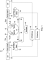
- FIG. 1 schematically illustrates a general architecture layout of a SBS laser gyroscope 100, according to one embodiment.
- the SBS laser gyroscope 100 includes an optical resonator such as a ring resonator 110, which is in optical communication with a first laser device such as a first pump laser 120, and a second laser device such as a second pump laser 124, through an optical path such as an input bus waveguide 130.
- ring resonator 110 can be a fiber optic coil wound around a core and about an axis around which rotation is sensed.
- ring resonator 110 can be formed on an optical chip using waveguides.
- a first intensity controller 122 is optically coupled between an output of first pump laser 120 and a first end 132 of input bus waveguide 130.
- a second intensity controller 126 is optically coupled between an output of second pump laser 124 and an opposite second end 134 of input bus waveguide 130.
- the input bus waveguide 130 is optically coupled to ring resonator 110 at an input coupling region 112 on a first side of ring resonator 110.
- An output bus waveguide 150 is optically coupled to ring resonator 110 at an output coupling region 114.
- a first optical detector 140 is in optical communication with ring resonator 110 through a CW transmission port 152 of output bus waveguide 150.
- a second optical detector 144 is in optical communication with ring resonator 110 through a CCW transmission port 154 of output bus waveguide 150.
- a rate detector 148 is in optical communication with ring resonator 110 through both CW and CCW transmission ports 152, 154.
- a first control loop device such as a CCW control loop 160 is operatively coupled between an output of first optical detector 140 and an input of second intensity controller 126.
- a second control loop device such as a CW control loop 164 is operatively coupled between an output of second optical detector 144 and an input of first intensity controller 122.
- first laser pump 120 emits a first optical signal that propagates in a first direction to first intensity controller 122, which processes the first optical signal to produce a first intensity modulated (IM) pump signal (Pcw).
- the first IM pump signal is modulated at frequency of f1 and is sent to ring resonator 110 through input bus waveguide 130.
- the first IM pump signal is coupled into ring resonator 110 at input coupling region 112 and propagates in a CW direction (Pin cw) in ring resonator 110.
- a CCW first-order SBS signal (P SBS-CCW ) is generated in optical resonator 110 and counter-propagates in the CCW direction.
- the intensity of the CCW first-order SBS signal is measured by optical detector 144. Without 2 nd order SBS, the intensity of the CCW first-order SBS signal is also modulated at the frequency of f1, because the input CW pump, the first IM pump, is modulated at the frequency of f1.
- the second laser pump 124 emits a second optical signal that propagates in a second opposite direction to second intensity controller 126, which processes the second optical signal to produce a second IM pump signal (P CCW ).
- the second IM pump signal is modulated at frequency of f2 and is sent to ring resonator 110 through input bus waveguide 130.
- the second IM pump signal is coupled into ring resonator 110 at input coupling region 112 and propagates in a CCW direction (Pin ccw) in ring resonator 110.
- a CW first-order SBS signal (P SBS-CW ) is generated in optical resonator 110 and counter-propagates in the CW direction.
- the intensity of the CW first-order SBS signal is measured by optical detector 140. Without 2 nd order SBS, the intensity of the CW first-order SBS signal is also modulated at the frequency of f2, because the input CCW pump, the second IM pump, is modulated at the frequency of f2.
- the first optical detector 140 is operative to receive the first transmitted IM pump signal (P in_CW ) and CW first-order SBS signal (P SBS-CW modulated at f2), which are coupled out of ring resonator 110 at output coupling region 114 and into output bus waveguide 150.
- the second optical detector 144 is operative to receives the second transmitted IM pump signal (P in_ ccw) and the CCW first-order SBS signal (P SBS-CCW modulated at f1), which are coupled out of ring resonator 110 at output coupling region 114 and into output bus waveguide 150.
- the signals coupled out of ring resonator 110 are also sent to rate detector 148 via output bus waveguide 150 for further processing to determine rotation rates.
- the CCW control loop 160 is configured to receive an electrical signal at f2 from first optical detector 140.
- the CCW control loop 160 is operative to minimize the electrical signal at f2 by adjusting intensity controller 126 to control the direct current (DC) pump power in the CCW direction.
- the CW control loop 164 is configured to receive an electrical signal at f1 from second optical detector 144.
- the CW control loop 164 is operative to minimize the electrical signal at f1 by adjusting intensity controller 122 to control the DC pump power in the CW direction.
- FIG. 2 is a schematic diagram illustrating a portion of a SBS laser gyroscope 200, according to this implementation.
- the SBS laser gyroscope 200 includes a ring resonator 210, which is in configured to receive a CW pump signal 220 and a CCW pump signal 224, from respective CW and CCW pump lasers, through an input bus waveguide 230.
- a first input pump monitor 234 is operative to monitor the intensity of CW pump signal 220
- a second input pump monitor 236 is operative to monitor the intensity of CCW pump signal 224.
- the ring resonator 210 is in optical communication with a CW transmission port 242 and a CCW transmission port 244 through an output bus waveguide 250.
- the method increases a power level of the CW pump signal 220 to above a threshold level such that a CCW first-order SBS signal generates a CW second-order SBS signal in ring resonator 210.
- the second-order SBS pump threshold is usually about four times the first-order SBS pump threshold.
- the method also increases a power level of CCW pump signal 224 to above the threshold level such that a CW first-order SBS signal generates a CCW second-order SBS signal in ring resonator 210. Above the second-order SBS threshold level, the first-order SBS signals are clamped at substantially the same power level.
- the input pump monitors 234 and 236 provide a feedback to the pump power to maintain the power level of the second-order SBS signals as needed.
- a Kerr effect bias instability of SBS laser gyroscope 200 is reduced or eliminated by the generated second-order SBS signals and the clamped first-order SBS signals.
- the pump threshold for 2 nd order SBS generation can be exactly four times the pump threshold (P Threshold ) for 1 st order SBS generation.
- the pump threshold is measured for 1 st order SBS generation, and both CW and CCW pump power can be set to a level that is slightly higher than four times (4X) of the first pump threshold (such as 4.2X). In this case, both CW and CCW 1 st order SBS are clamped at an intracavity pump threshold.
- Figure 3 is a time plot 300 illustrating the method for reducing or eliminating the Kerr effect bias instability in the SBS laser gyroscope.
- first-order SBS signals are generated in the ring resonator with a same modulation period.
- second-order SBS threshold 310 the first-order SBS signals are clamped at a given power level and generate second-order SBS signals in the ring resonator.
- the second-order SBS signals can then be intensity modulated at a second-order SBS power over a second time period.
- a plot curve 320 represents the intensity of the first-order SBS signals, which becomes stable at about 0.010 seconds and gets clamped at about 0.25 without intensity modulation. Even if the pump power is increased, the first-order SBS power does not change since it is clamped as the pump for second-order SBS generation. Above this point, the intensity of the second-order SBS signals, represented by a plot curve 330, increases with a large amplitude modulation.
- the launching pump power is defined as P P In .
- P P In To stabilize the input directly: P P In ;
- P P In P th To stabilize the SBS power: P P In P th .
- P th ⁇ Loss g B ⁇ L / 1 + 2 ⁇ GP ⁇ SBS ⁇ B 2
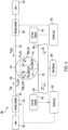
- FIG. 4 schematically illustrates a SBS laser gyroscope 400, according to another embodiment.
- the SBS laser gyroscope 400 includes a ring resonator 410, which is in optical communication with a first pump laser 420 via an input bus waveguide 430.
- a first intensity controller 422 is optically coupled between an output of first pump laser 420 and a first end 432 of input bus waveguide 430.
- the SBS laser gyroscope 400 also includes a second pump laser 424, which is in optical communication with ring resonator 410 through input bus waveguide 430.
- a second intensity controller 426 is optically coupled between an output of second pump laser 424 and an opposite second end 434 of input bus waveguide 430.
- the input bus waveguide 430 is optically coupled to ring resonator 410 at an input coupling region 412 on a first side of ring resonator 410.
- An output bus waveguide 436 is optically coupled to ring resonator 410 at an output coupling region 414 on an opposing second side of ring resonator 410.
- a first high frequency optical detector 440 such as a 21.6 GHz detector, is in optical communication with ring resonator 410 through a CW transmission port 438 of output bus waveguide 436.
- a first intensity control loop 450 is operatively coupled between an output of first optical detector 440 and an input of first intensity controller 422.
- a second high frequency optical detector 442 such as a 21.6 GHz detector, is in optical communication with ring resonator 410 through a CCW transmission port 439 of output bus waveguide 436.
- a second intensity control loop 452 is operatively coupled between an output of the second optical detector 442 and an input of second intensity controller 426.
- a rate detector 446 is in optical communication with ring resonator 410 through both CW and CCW transmission ports 438, 439.
- the SBS laser gyroscope 400 is particularly suited for a method of locking the pump laser at a level when 21.6 GHz is detected.
- first laser pump 420 emits a first optical signal that propagates to first intensity controller 422, which processes the first optical signal to produce a first pump signal (P CW ) that is sent to ring resonator 410 through input bus waveguide 430.
- the first pump signal is coupled into ring resonator 410 at input coupling region 412 and propagates in a CW direction (P in_CW ) in ring resonator 410.
- a CCW first-order SBS signal (P SBS-CCW ) is generated in optical resonator 410 and counter-propagates in the CCW direction.
- a second pump signal (P CCW ) that is sent from second pump laser 424 to ring resonator 410 through input bus waveguide 430.
- the second pump signal is coupled into ring resonator 410 at input coupling region 412 and propagates in a CCW direction (P in_CCW ) in ring resonator 410.
- a CW first-order SBS signal (P SBS-CW ) is generated in optical resonator 410 and counter-propagates in the CW direction.
- the optical detector 440 receives the first pump signal (Pin cw), the CW first-order SBS signal (P SBS-CW ), and the CW 2 nd order SBS signal (P 2nd-SBS-CW ), which are coupled out of ring resonator 410 at output coupling region 414 and into output bus waveguide 436.
- the first intensity control loop 450 is configured to receive a first electrical signal from optical detector 440.
- the optical detector 440 is used to monitor the beat frequency between first pump signal (P in_ cw) and CW 2 nd order SBS signal (P 2nd-SBS-CW ).
- the beat frequency is usually at 21.6 GHz for a silica based waveguide.
- the first intensity control loop 450 is operative to minimize the first electrical signal by adjusting first intensity controller 422 to control the DC pump power in the CW direction.
- the optical detector 442 receives the second pump signal (Pin ccw), the CCW first-order SBS signal (P SBS-CCW ), and the CCW 2 nd order SBS signal (P 2nd-SBS-CCW ), which are coupled out of ring resonator 410 at output coupling region 414 and into output bus waveguide 436.
- the second intensity control loop 452 is configured to receive a second electrical signal from second optical detector 442.
- the optical detector 442 is used to monitor the beat frequency between first pump signal (Pin ccw) and CCW 2 nd order SBS signal (P 2nd-SBS-CCW ).
- the beat frequency is usually at 21.6 GHz for a silica based waveguide.
- the second intensity control loop 452 is operative to minimize the second electrical signal by adjusting second intensity controller 426 to control the DC pump power in the CCW direction.
- the power of the pump lasers are increased to above a second-order SBS threshold to produce a CW second-order SBS signal (P 2nd_SBS-CW ) and a CCW second-order SBS signal (P 2nd_SBS-CCW ) that counter-propagate in resonator 410.
- the first-order SBS power signals are clamped, and the second-order SBS power signals are intensity modulated.
- Figure 5 is a graph representing the operation of SBS laser gyroscope 400.
- the graph of Figure 5 depicts the frequency (f) of the light at the CW transmission port with respect to intensity.
- the frequency span between the first pump signal (f P_CW ) and the CW first-order SBS signal (f SBS_CW ) is 10.8 GHz.
- the frequency span between the first pump signal and the CW second-order SBS signal (f 2nd SBS_CW ) is 21.6 GHz.
- the intensity control loops are used to keep the 21.6 GHz signal at a fixed small value.
Landscapes
- Physics & Mathematics (AREA)
- Electromagnetism (AREA)
- Engineering & Computer Science (AREA)
- Optics & Photonics (AREA)
- Plasma & Fusion (AREA)
- Power Engineering (AREA)
- General Physics & Mathematics (AREA)
- Radar, Positioning & Navigation (AREA)
- Remote Sensing (AREA)
- Lasers (AREA)
- Gyroscopes (AREA)
Description
- This invention was made with Government support under Contract No. N6600116C4017 awarded by SPAWAR (now NIWC). The Government has certain rights in the invention.
- The stimulated Brillouin scattering (SBS) laser gyroscope is a promising technology for next generation gyroscopes due to its simplicity and potential for miniaturization. The SBS lasers in such gyroscopes have very low phase noise due to short phonon lifetime. As in all optical gyroscopes based on waveguides, the SBS laser gyroscope has bias errors due to the gyroscope Kerr effect.
- The Kerr effect is caused by the difference between cross-phase modulation and self-phase modulation. These two different phase modulations generate different refractive index changes that cause a bias in rotation measurements. The variation of such differences generates the bias instability, which is one of the fundamental bias errors in waveguide based gyroscopes.
-
US 2019/017824 A1 relates to an apparatus and method for diminishing mode lock induced error in stimulated Brillouin scattering waveguide ring laser gyroscopes. -
WO 2010/077527 A1 relates to optical devices, and is particularly applicable to optical devices such as optical sensors, that incorporate a substantially planar microresonator that includes a non-planar portion. -
US5351252 A relates generally to Brillouin Fiber Optic Gyroscopes, and more particularly to an apparatus and method for reducing the Kerr effect and extending the dynamic range of a Brillouin Fiber Optic Gyroscope. - The present invention is defined by the independent claim, to which reference should now be made.
- Understanding that the drawings depict only exemplary embodiments and are not therefore to be considered limiting in scope, the exemplary embodiments will be described with additional specificity and detail through the use of the accompanying drawings, in which:
-
Figure 1 is a schematic diagram of a stimulated Brillouin scattering (SBS) laser gyroscope, according to one embodiment; -
Figure 2 is a schematic diagram of a portion of a SBS laser gyroscope, according to an exemplary implementation; -
Figure 3 is a time plot representing a method for reducing or eliminating a Kerr effect bias instability in a SBS laser gyroscope; -
Figure 4 is a schematic diagram of a SBS laser gyroscope, according to another embodiment; and -
Figure 5 is a graph representing the operation of the SBS laser gyroscope ofFigure 4 . - In the following detailed description, embodiments are described in sufficient detail to enable those skilled in the art to practice the invention. It is to be understood that other embodiments may be utilized without departing from the scope of the invention. The following detailed description is, therefore, not to be taken in a limiting sense.
- A method for Kerr effect reduction in stimulated Brillouin scattering (SBS) laser gyroscopes is described herein. The Kerr effect is one of the fundamental bias errors that need to be reduced to achieve navigation grade performance for SBS laser gyroscopes. The bias instability due to the Kerr effect mainly depends on the intracavity power difference between clockwise (CW) and counterclockwise (CCW) SBS lasers that are used for rate detection in SBS laser gyroscopes. The present method is based on a laser pump power clamping technique that eliminates such bias errors.
- In general, the present approach provides for increasing the laser pump power so that a first SBS power (both CW and CCW) reaches a threshold and starts to generate a second SBS power. A first SBS laser becomes the pump laser for the second SBS power, and the first SBS power is clamped at a level to satisfy the steady state condition, which is that the gain should be equal to cavity loss. Because the cavity loss is reciprocal, the gain of the second SBS power should be same for both the CW and CCW directions. Therefore, the first SBS power in the CW and CCW directions is the same. This reduces or eliminates the Kerr effect in the SBS laser gyroscope.
- In resonator-based gyroscopes such as SBS laser gyroscopes, one fundamental limit is the Kerr effect due to the unbalance of the CW and CCW power. In a steady state laser, gain is equal to loss, and the intracavity pump is clamped at the level that satisfies the lasing threshold. The wave propagation equation and Kerr effect can be described by the following expressions:


- Above a second-order SBS threshold, the first order SBS becomes the pump for 2nd order SBS generation, and the 1st order SBS intensity is clamped at Ip. Since the cavity loss (α) is reciprocal, the CW and CCW threshold are the same. Therefore, both CW and CCW 1st order SBS have the same intracavity intensity:

- One method for reducing or eliminating bias instability in a SBS laser gyroscope comprises modulating the intensities of a CW pump signal and a CCW pump signal, such that a CCW first-order SBS signal and a CW first-order SBS signal are generated in an optical resonator of the gyroscope. The method increases a power level of the CW pump signal to above a threshold level such that the CCW first-order SBS signal generates a CW second-order SBS signal in the resonator. The method also increases a power level of the CCW pump signal to above the threshold level such that the CW first-order SBS signal generates a CCW second-order SBS signal in the resonator. At above the threshold level, the first-order SBS signals are clamped at substantially the same power level.
- The present methods provides the benefit of stabilizing laser power in the resonator of a SBS laser gyroscope. The method increases the pump power sufficiently such that the first-order SBS power becomes the pump that generates the second-order SBS power. The first-order SBS power is clamped and remains constant in both the CW and CCW directions. The method allows the CW power to be equal to the CCW power in the gyroscope.
- The present approach allows a reciprocal gyroscope to be operated with the same CW and CCW power, such that Kerr biases are eliminated. The constant power is ensured by operating the gyroscope above the second-order SBS threshold, thereby reducing or eliminating bias instability due to the Kerr effect.
- Further details of various embodiments are described hereafter with reference to the drawings.
-
Figure 1 schematically illustrates a general architecture layout of a SBSlaser gyroscope 100, according to one embodiment. The SBSlaser gyroscope 100 includes an optical resonator such as aring resonator 110, which is in optical communication with a first laser device such as afirst pump laser 120, and a second laser device such as asecond pump laser 124, through an optical path such as aninput bus waveguide 130. In one embodiment,ring resonator 110 can be a fiber optic coil wound around a core and about an axis around which rotation is sensed. In another embodiment,ring resonator 110 can be formed on an optical chip using waveguides. - A
first intensity controller 122 is optically coupled between an output offirst pump laser 120 and afirst end 132 ofinput bus waveguide 130. Asecond intensity controller 126 is optically coupled between an output ofsecond pump laser 124 and an opposite second end 134 ofinput bus waveguide 130. - The
input bus waveguide 130 is optically coupled toring resonator 110 at aninput coupling region 112 on a first side ofring resonator 110. Anoutput bus waveguide 150 is optically coupled toring resonator 110 at anoutput coupling region 114. - A first
optical detector 140 is in optical communication withring resonator 110 through aCW transmission port 152 ofoutput bus waveguide 150. A secondoptical detector 144 is in optical communication withring resonator 110 through aCCW transmission port 154 ofoutput bus waveguide 150. Arate detector 148 is in optical communication withring resonator 110 through both CW andCCW transmission ports - A first control loop device such as a
CCW control loop 160 is operatively coupled between an output of firstoptical detector 140 and an input ofsecond intensity controller 126. A second control loop device such as aCW control loop 164 is operatively coupled between an output of secondoptical detector 144 and an input offirst intensity controller 122. - During operation,
first laser pump 120 emits a first optical signal that propagates in a first direction tofirst intensity controller 122, which processes the first optical signal to produce a first intensity modulated (IM) pump signal (Pcw). The first IM pump signal is modulated at frequency of f1 and is sent to ringresonator 110 throughinput bus waveguide 130. The first IM pump signal is coupled intoring resonator 110 atinput coupling region 112 and propagates in a CW direction (Pin cw) inring resonator 110. A CCW first-order SBS signal (PSBS-CCW) is generated inoptical resonator 110 and counter-propagates in the CCW direction. The intensity of the CCW first-order SBS signal is measured byoptical detector 144. Without 2nd order SBS, the intensity of the CCW first-order SBS signal is also modulated at the frequency of f1, because the input CW pump, the first IM pump, is modulated at the frequency of f1. - The
second laser pump 124 emits a second optical signal that propagates in a second opposite direction tosecond intensity controller 126, which processes the second optical signal to produce a second IM pump signal (PCCW). The second IM pump signal is modulated at frequency of f2 and is sent to ringresonator 110 throughinput bus waveguide 130. The second IM pump signal is coupled intoring resonator 110 atinput coupling region 112 and propagates in a CCW direction (Pin ccw) inring resonator 110. A CW first-order SBS signal (PSBS-CW) is generated inoptical resonator 110 and counter-propagates in the CW direction. The intensity of the CW first-order SBS signal is measured byoptical detector 140. Without 2nd order SBS, the intensity of the CW first-order SBS signal is also modulated at the frequency of f2, because the input CCW pump, the second IM pump, is modulated at the frequency of f2. - The first
optical detector 140 is operative to receive the first transmitted IM pump signal (Pin_CW) and CW first-order SBS signal (PSBS-CW modulated at f2), which are coupled out ofring resonator 110 atoutput coupling region 114 and intooutput bus waveguide 150. The secondoptical detector 144 is operative to receives the second transmitted IM pump signal (Pin_ccw) and the CCW first-order SBS signal (PSBS-CCW modulated at f1), which are coupled out ofring resonator 110 atoutput coupling region 114 and intooutput bus waveguide 150. The signals coupled out ofring resonator 110 are also sent torate detector 148 viaoutput bus waveguide 150 for further processing to determine rotation rates. - The
CCW control loop 160 is configured to receive an electrical signal at f2 from firstoptical detector 140. TheCCW control loop 160 is operative to minimize the electrical signal at f2 by adjustingintensity controller 126 to control the direct current (DC) pump power in the CCW direction. TheCW control loop 164 is configured to receive an electrical signal at f1 from secondoptical detector 144. TheCW control loop 164 is operative to minimize the electrical signal at f1 by adjustingintensity controller 122 to control the DC pump power in the CW direction. - In another implementation without a feedback control loop, the pump is preset at a level that can generate 2nd order SBS in the cavity.
Figure 2 is a schematic diagram illustrating a portion of aSBS laser gyroscope 200, according to this implementation. - The
SBS laser gyroscope 200 includes aring resonator 210, which is in configured to receive aCW pump signal 220 and aCCW pump signal 224, from respective CW and CCW pump lasers, through aninput bus waveguide 230. A first input pump monitor 234 is operative to monitor the intensity ofCW pump signal 220, and a second input pump monitor 236 is operative to monitor the intensity ofCCW pump signal 224. Thering resonator 210 is in optical communication with aCW transmission port 242 and aCCW transmission port 244 through anoutput bus waveguide 250. - In a method for reducing or eliminating bias instability in
SBS laser gyroscope 200, the method increases a power level of theCW pump signal 220 to above a threshold level such that a CCW first-order SBS signal generates a CW second-order SBS signal inring resonator 210. The second-order SBS pump threshold is usually about four times the first-order SBS pump threshold. The method also increases a power level ofCCW pump signal 224 to above the threshold level such that a CW first-order SBS signal generates a CCW second-order SBS signal inring resonator 210. Above the second-order SBS threshold level, the first-order SBS signals are clamped at substantially the same power level. The input pump monitors 234 and 236 provide a feedback to the pump power to maintain the power level of the second-order SBS signals as needed. A Kerr effect bias instability ofSBS laser gyroscope 200 is reduced or eliminated by the generated second-order SBS signals and the clamped first-order SBS signals. - In the SBS laser gyroscope 200 (
Fig. 2 ), the pump threshold for 2nd order SBS generation can be exactly four times the pump threshold (PThreshold) for 1st order SBS generation. In the implementation ofFigure 2 , the pump threshold is measured for 1st order SBS generation, and both CW and CCW pump power can be set to a level that is slightly higher than four times (4X) of the first pump threshold (such as 4.2X). In this case, both CW and CCW 1st order SBS are clamped at an intracavity pump threshold. -
Figure 3 is atime plot 300 illustrating the method for reducing or eliminating the Kerr effect bias instability in the SBS laser gyroscope. When the pump signals are intensity modulated, first-order SBS signals are generated in the ring resonator with a same modulation period. When the pump signals are increased in intensity to above a second-order SBS threshold 310, the first-order SBS signals are clamped at a given power level and generate second-order SBS signals in the ring resonator. The second-order SBS signals can then be intensity modulated at a second-order SBS power over a second time period. - For example, as shown in
Figure 3 , aplot curve 320 represents the intensity of the first-order SBS signals, which becomes stable at about 0.010 seconds and gets clamped at about 0.25 without intensity modulation. Even if the pump power is increased, the first-order SBS power does not change since it is clamped as the pump for second-order SBS generation. Above this point, the intensity of the second-order SBS signals, represented by aplot curve 330, increases with a large amplitude modulation. - The foregoing method is described in further detail as follows. To stabilize the SBS power, the launching pump power is defined as


- The intracavity SBS power is defined by the expression:

- At the CW transmission port, the transmitted power (PTX,CW)is described by:

-
Figure 4 schematically illustrates aSBS laser gyroscope 400, according to another embodiment. TheSBS laser gyroscope 400 includes aring resonator 410, which is in optical communication with afirst pump laser 420 via aninput bus waveguide 430. Afirst intensity controller 422 is optically coupled between an output offirst pump laser 420 and afirst end 432 ofinput bus waveguide 430. - The
SBS laser gyroscope 400 also includes asecond pump laser 424, which is in optical communication withring resonator 410 throughinput bus waveguide 430. Asecond intensity controller 426 is optically coupled between an output ofsecond pump laser 424 and an oppositesecond end 434 ofinput bus waveguide 430. - The
input bus waveguide 430 is optically coupled toring resonator 410 at aninput coupling region 412 on a first side ofring resonator 410. Anoutput bus waveguide 436 is optically coupled toring resonator 410 at anoutput coupling region 414 on an opposing second side ofring resonator 410. A first high frequencyoptical detector 440, such as a 21.6 GHz detector, is in optical communication withring resonator 410 through aCW transmission port 438 ofoutput bus waveguide 436. A firstintensity control loop 450 is operatively coupled between an output of firstoptical detector 440 and an input offirst intensity controller 422. - A second high frequency
optical detector 442, such as a 21.6 GHz detector, is in optical communication withring resonator 410 through aCCW transmission port 439 ofoutput bus waveguide 436. A secondintensity control loop 452 is operatively coupled between an output of the secondoptical detector 442 and an input ofsecond intensity controller 426. Arate detector 446 is in optical communication withring resonator 410 through both CW andCCW transmission ports - The
SBS laser gyroscope 400 is particularly suited for a method of locking the pump laser at a level when 21.6 GHz is detected. During operation,first laser pump 420 emits a first optical signal that propagates tofirst intensity controller 422, which processes the first optical signal to produce a first pump signal (PCW) that is sent to ringresonator 410 throughinput bus waveguide 430. The first pump signal is coupled intoring resonator 410 atinput coupling region 412 and propagates in a CW direction (Pin_CW) inring resonator 410. A CCW first-order SBS signal (PSBS-CCW) is generated inoptical resonator 410 and counter-propagates in the CCW direction. - A second pump signal (PCCW) that is sent from
second pump laser 424 to ringresonator 410 throughinput bus waveguide 430. The second pump signal is coupled intoring resonator 410 atinput coupling region 412 and propagates in a CCW direction (Pin_CCW) inring resonator 410. A CW first-order SBS signal (PSBS-CW) is generated inoptical resonator 410 and counter-propagates in the CW direction. - The
optical detector 440 receives the first pump signal (Pin cw), the CW first-order SBS signal (PSBS-CW), and the CW 2nd order SBS signal (P2nd-SBS-CW), which are coupled out ofring resonator 410 atoutput coupling region 414 and intooutput bus waveguide 436. The firstintensity control loop 450 is configured to receive a first electrical signal fromoptical detector 440. Theoptical detector 440 is used to monitor the beat frequency between first pump signal (Pin_cw) and CW 2nd order SBS signal (P2nd-SBS-CW). The beat frequency is usually at 21.6 GHz for a silica based waveguide. The firstintensity control loop 450 is operative to minimize the first electrical signal by adjustingfirst intensity controller 422 to control the DC pump power in the CW direction. - The
optical detector 442 receives the second pump signal (Pin ccw), the CCW first-order SBS signal (PSBS-CCW), and the CCW 2nd order SBS signal (P2nd-SBS-CCW), which are coupled out ofring resonator 410 atoutput coupling region 414 and intooutput bus waveguide 436. The secondintensity control loop 452 is configured to receive a second electrical signal from secondoptical detector 442. Theoptical detector 442 is used to monitor the beat frequency between first pump signal (Pin ccw) and CCW 2nd order SBS signal (P2nd-SBS-CCW). The beat frequency is usually at 21.6 GHz for a silica based waveguide. The secondintensity control loop 452 is operative to minimize the second electrical signal by adjustingsecond intensity controller 426 to control the DC pump power in the CCW direction. - The power of the pump lasers are increased to above a second-order SBS threshold to produce a CW second-order SBS signal (P2nd_SBS-CW ) and a CCW second-order SBS signal (P2nd_SBS-CCW) that counter-propagate in
resonator 410. The first-order SBS power signals are clamped, and the second-order SBS power signals are intensity modulated. -
Figure 5 is a graph representing the operation ofSBS laser gyroscope 400. The graph ofFigure 5 depicts the frequency (f) of the light at the CW transmission port with respect to intensity. As shown, the frequency span between the first pump signal (fP_CW) and the CW first-order SBS signal (fSBS_CW) is 10.8 GHz. The frequency span between the first pump signal and the CW second-order SBS signal (f2nd SBS_CW) is 21.6 GHz. The intensity control loops are used to keep the 21.6 GHz signal at a fixed small value.
Claims (1)
- A stimulated Brillouin scattering, SBS, laser gyroscope, comprising:a first input pump laser configured to emit a clockwise, CW, pump signal;a second input pump laser configured to emit a counterclockwise, CCW, pump signal;a first input pump monitor operative to monitor an intensity of the CW pump signal (220);a second input pump monitor operative to monitor an intensity of the CCW pump signal (224); anda ring resonator (110, 210, 410) in optical communication with the first pump laser (120, 420) and the second pump laser (124, 424), the ring resonator (110, 210, 410) configured to receive the CW pump signal (220) and the CCW pump signal (224) through an input bus waveguide (130, 230, 430);characterized in that:
the ring resonator (110, 210, 410) is in optical communication with a CW transmission port (242) and a CCW transmission port (244) through an output bus waveguide (150, 250, 436), wherein:a power level of the CW pump signal (220) is increased to above a threshold level such that a CCW first-order SBS signal generates a CW second-order SBS signal in the ring resonator (110, 210, 410);the first input pump monitor is operative to maintain the power level of the CW pump signal (220) above the threshold level to generate the CW second-order SBS signal;a power level of the CCW pump signal (224) is increased to above the threshold level such that a CW first-order SBS signal generates a CCW second-order SBS signal in the ring resonator (110, 210, 410);the second input pump monitor is operative to maintain the power level of the CCW pump signal (224) above the threshold level to generate the CCW second-order SBS signal;above the threshold level, the first-order SBS signals are clamped at substantially the same power level; anda Kerr effect bias instability of the SBS laser gyroscope (100, 200, 400) is reduced or eliminated by the clamped first-order SBS signals.
Applications Claiming Priority (2)
| Application Number | Priority Date | Filing Date | Title |
|---|---|---|---|
| US16/858,272 US11486706B2 (en) | 2020-04-24 | 2020-04-24 | Kerr effect reduction in SBS laser gyroscope |
| EP21157733.3A EP3961152B1 (en) | 2020-04-24 | 2021-02-17 | Kerr effect reduction in sbs laser gyroscope |
Related Parent Applications (1)
| Application Number | Title | Priority Date | Filing Date |
|---|---|---|---|
| EP21157733.3A Division EP3961152B1 (en) | 2020-04-24 | 2021-02-17 | Kerr effect reduction in sbs laser gyroscope |
Publications (2)
| Publication Number | Publication Date |
|---|---|
| EP4230959A1 EP4230959A1 (en) | 2023-08-23 |
| EP4230959B1 true EP4230959B1 (en) | 2024-08-28 |
Family
ID=74668619
Family Applications (2)
| Application Number | Title | Priority Date | Filing Date |
|---|---|---|---|
| EP21157733.3A Active EP3961152B1 (en) | 2020-04-24 | 2021-02-17 | Kerr effect reduction in sbs laser gyroscope |
| EP23162940.3A Active EP4230959B1 (en) | 2020-04-24 | 2021-02-17 | Kerr effect reduction in sbs laser gyroscope |
Family Applications Before (1)
| Application Number | Title | Priority Date | Filing Date |
|---|---|---|---|
| EP21157733.3A Active EP3961152B1 (en) | 2020-04-24 | 2021-02-17 | Kerr effect reduction in sbs laser gyroscope |
Country Status (2)
| Country | Link |
|---|---|
| US (1) | US11486706B2 (en) |
| EP (2) | EP3961152B1 (en) |
Families Citing this family (4)
| Publication number | Priority date | Publication date | Assignee | Title |
|---|---|---|---|---|
| US12614889B1 (en) * | 2022-01-18 | 2026-04-28 | Hqphotonics Inc. | Narrow-linewidth brillouin laser stabilized by optical self-injection locking |
| US12492902B2 (en) | 2022-06-22 | 2025-12-09 | Honeywell International Inc. | Modulation methods and systems for non-reciprocal Kerr reduction in resonator fiber optic gyroscopes |
| US12516936B2 (en) * | 2023-08-22 | 2026-01-06 | Honeywell International Inc. | Apparatus and method for enhanced beat note detection |
| CN117856759B (en) * | 2024-03-07 | 2024-05-24 | 山东大学 | Method and apparatus for achieving frequency tuning and spectral broadening of cantilever microresonators |
Family Cites Families (10)
| Publication number | Priority date | Publication date | Assignee | Title |
|---|---|---|---|---|
| US4396290A (en) * | 1979-09-24 | 1983-08-02 | University Of Utah Research Institute | Two pump-frequency-stimulated Brillouin scattering ring laser gyroscope |
| US5351252A (en) | 1993-02-26 | 1994-09-27 | The Board Of Trustees Of The Leland Stanford University | Technique of reducing the Kerr effect and extending the dynamic range in a Brillouin fiber optic gyroscope |
| US5537671A (en) | 1995-02-10 | 1996-07-16 | The Board Of Trustees Of The Leland Stanford Junior University | Technique of reducing the Kerr effect and extending the dynamic range in a brillouin fiber optic gyroscope |
| WO2010077527A1 (en) * | 2008-12-29 | 2010-07-08 | 3M Innovative Properties Company | Optical microresonator |
| US9083147B2 (en) | 2011-10-28 | 2015-07-14 | Ofs Fitel, Llc | Distributed feedback (DFB) Brillouin fiber lasers |
| US8830478B2 (en) | 2012-12-04 | 2014-09-09 | Honeywell International Inc. | Optical frequency comb stimulated Brillouin scattering gyroscope |
| US9733084B2 (en) | 2015-09-09 | 2017-08-15 | Honeywell International Inc. | Single pump cascaded stimulated Brillouin scattering (SBS) ring laser gyro |
| US10288429B2 (en) * | 2017-06-01 | 2019-05-14 | Honeywell International Inc. | Apparatus and method for diminishing mode lock induced error in stimulated brillouin scattering waveguide ring laser gyroscopes |
| US10992097B2 (en) * | 2017-06-09 | 2021-04-27 | Honeywell International Inc. | Apparatus and method for an optical resonator with an integrated Bragg grating |
| WO2019213401A1 (en) | 2018-05-02 | 2019-11-07 | Massachusetts Institute Of Technology | Narrow-linewidth microcavity brillouin laser with suppressed temperature fluctuations |
-
2020
- 2020-04-24 US US16/858,272 patent/US11486706B2/en active Active
-
2021
- 2021-02-17 EP EP21157733.3A patent/EP3961152B1/en active Active
- 2021-02-17 EP EP23162940.3A patent/EP4230959B1/en active Active
Also Published As
| Publication number | Publication date |
|---|---|
| EP4230959A1 (en) | 2023-08-23 |
| EP3961152B1 (en) | 2023-04-05 |
| EP3961152A1 (en) | 2022-03-02 |
| US20210333106A1 (en) | 2021-10-28 |
| US11486706B2 (en) | 2022-11-01 |
Similar Documents
| Publication | Publication Date | Title |
|---|---|---|
| EP4230959B1 (en) | Kerr effect reduction in sbs laser gyroscope | |
| EP1562315B1 (en) | Pump light source device for raman amplification | |
| US6738408B2 (en) | Mode-locked laser apparatus | |
| US8885678B1 (en) | Ultra-low frequency noise external cavity semiconductor laser with integrated waveguide grating and modulation section electronically stabilized by dual frequency feedback control circuitry | |
| US5331404A (en) | Low noise fiber gyroscope system which includes excess noise subtraction | |
| US8054539B2 (en) | Optical system for reducing stimulated Brillouin scattering by controllably changing polarization direction of an optical signal | |
| US6377391B1 (en) | Gain flattening with nonlinear Sagnac amplifiers | |
| EP2423641B1 (en) | Resonator fiber optic gyroscopes with reduced rotation rate instability from back reflections | |
| EP2293014A2 (en) | Resonator optical gyroscope having input beam modulation optimized for high sensitivity and low bias | |
| EP2698605B1 (en) | Fiber resonator gyroscope with low round trip loss and high output power | |
| US10928200B1 (en) | Frequency pulling reduction in SBS laser | |
| US6744947B2 (en) | High power, low noise, fluorescent device and methods related thereto | |
| US4968110A (en) | Apparatus and method for optimizing the modulation efficiency of a remotely-located, polarization-sensitive, integrated optic modulator which is addressed with a non-polarization-preserving fiber | |
| US12546603B2 (en) | Optical gyroscope with broadband comb interrogation | |
| EP4481327A1 (en) | Integrated photonics gyroscope with common intensity modulation | |
| EP4484892A1 (en) | Closed loop operation of broadband resonator optical gyroscope using sawtooth phase modulations | |
| US12405111B2 (en) | Resonator optical gyroscopes with dual broadband light sources | |
| US12618674B2 (en) | Interferometric resonator optical gyroscope with optical frequency comb | |
| EP4462074B1 (en) | Resonant optical gyroscope with broadband light source and rin reduction techniques | |
| US20260063422A1 (en) | Interferometric resonator optical gyroscope with optical frequency comb | |
| EP4495548A1 (en) | Broadband resonator optical gyroscope with efficient optical power management for low shot noise | |
| He et al. | Parity-time-symmetric optomechanically microwave oscillator based on the torsional radial acoustic modes with a single dual-polarization optical loop | |
| Hui et al. | Pump RIN to Carrier Phase Noise Transfer in Distributed Fiber Raman System Evaluated through Carrier FM Noise Spectrum | |
| JPH0240632A (en) | Fiber brillouin optical amplifying repeater | |
| Belkin et al. | Phase Stabilization in Onboard Microwave-Band Fiber-Optic Link |
Legal Events
| Date | Code | Title | Description |
|---|---|---|---|
| PUAI | Public reference made under article 153(3) epc to a published international application that has entered the european phase |
Free format text: ORIGINAL CODE: 0009012 |
|
| STAA | Information on the status of an ep patent application or granted ep patent |
Free format text: STATUS: THE APPLICATION HAS BEEN PUBLISHED |
|
| AC | Divisional application: reference to earlier application |
Ref document number: 3961152 Country of ref document: EP Kind code of ref document: P |
|
| AK | Designated contracting states |
Kind code of ref document: A1 Designated state(s): AL AT BE BG CH CY CZ DE DK EE ES FI FR GB GR HR HU IE IS IT LI LT LU LV MC MK MT NL NO PL PT RO RS SE SI SK SM TR |
|
| STAA | Information on the status of an ep patent application or granted ep patent |
Free format text: STATUS: REQUEST FOR EXAMINATION WAS MADE |
|
| 17P | Request for examination filed |
Effective date: 20230918 |
|
| RBV | Designated contracting states (corrected) |
Designated state(s): AL AT BE BG CH CY CZ DE DK EE ES FI FR GB GR HR HU IE IS IT LI LT LU LV MC MK MT NL NO PL PT RO RS SE SI SK SM TR |
|
| GRAP | Despatch of communication of intention to grant a patent |
Free format text: ORIGINAL CODE: EPIDOSNIGR1 |
|
| STAA | Information on the status of an ep patent application or granted ep patent |
Free format text: STATUS: GRANT OF PATENT IS INTENDED |
|
| INTG | Intention to grant announced |
Effective date: 20240328 |
|
| GRAS | Grant fee paid |
Free format text: ORIGINAL CODE: EPIDOSNIGR3 |
|
| GRAA | (expected) grant |
Free format text: ORIGINAL CODE: 0009210 |
|
| STAA | Information on the status of an ep patent application or granted ep patent |
Free format text: STATUS: THE PATENT HAS BEEN GRANTED |
|
| AC | Divisional application: reference to earlier application |
Ref document number: 3961152 Country of ref document: EP Kind code of ref document: P |
|
| AK | Designated contracting states |
Kind code of ref document: B1 Designated state(s): AL AT BE BG CH CY CZ DE DK EE ES FI FR GB GR HR HU IE IS IT LI LT LU LV MC MK MT NL NO PL PT RO RS SE SI SK SM TR |
|
| REG | Reference to a national code |
Ref country code: CH Ref legal event code: EP |
|
| P01 | Opt-out of the competence of the unified patent court (upc) registered |
Free format text: CASE NUMBER: APP_45294/2024 Effective date: 20240805 |
|
| REG | Reference to a national code |
Ref country code: DE Ref legal event code: R096 Ref document number: 602021018117 Country of ref document: DE |
|
| REG | Reference to a national code |
Ref country code: IE Ref legal event code: FG4D |
|
| REG | Reference to a national code |
Ref country code: LT Ref legal event code: MG9D |
|
| PG25 | Lapsed in a contracting state [announced via postgrant information from national office to epo] |
Ref country code: NO Free format text: LAPSE BECAUSE OF FAILURE TO SUBMIT A TRANSLATION OF THE DESCRIPTION OR TO PAY THE FEE WITHIN THE PRESCRIBED TIME-LIMIT Effective date: 20241128 |
|
| REG | Reference to a national code |
Ref country code: AT Ref legal event code: MK05 Ref document number: 1718388 Country of ref document: AT Kind code of ref document: T Effective date: 20240828 |
|
| PG25 | Lapsed in a contracting state [announced via postgrant information from national office to epo] |
Ref country code: PT Free format text: LAPSE BECAUSE OF FAILURE TO SUBMIT A TRANSLATION OF THE DESCRIPTION OR TO PAY THE FEE WITHIN THE PRESCRIBED TIME-LIMIT Effective date: 20241230 Ref country code: PL Free format text: LAPSE BECAUSE OF FAILURE TO SUBMIT A TRANSLATION OF THE DESCRIPTION OR TO PAY THE FEE WITHIN THE PRESCRIBED TIME-LIMIT Effective date: 20240828 Ref country code: NL Free format text: LAPSE BECAUSE OF FAILURE TO SUBMIT A TRANSLATION OF THE DESCRIPTION OR TO PAY THE FEE WITHIN THE PRESCRIBED TIME-LIMIT Effective date: 20240828 Ref country code: GR Free format text: LAPSE BECAUSE OF FAILURE TO SUBMIT A TRANSLATION OF THE DESCRIPTION OR TO PAY THE FEE WITHIN THE PRESCRIBED TIME-LIMIT Effective date: 20241129 Ref country code: FI Free format text: LAPSE BECAUSE OF FAILURE TO SUBMIT A TRANSLATION OF THE DESCRIPTION OR TO PAY THE FEE WITHIN THE PRESCRIBED TIME-LIMIT Effective date: 20240828 |
|
| PG25 | Lapsed in a contracting state [announced via postgrant information from national office to epo] |
Ref country code: BG Free format text: LAPSE BECAUSE OF FAILURE TO SUBMIT A TRANSLATION OF THE DESCRIPTION OR TO PAY THE FEE WITHIN THE PRESCRIBED TIME-LIMIT Effective date: 20240828 |
|
| PG25 | Lapsed in a contracting state [announced via postgrant information from national office to epo] |
Ref country code: LV Free format text: LAPSE BECAUSE OF FAILURE TO SUBMIT A TRANSLATION OF THE DESCRIPTION OR TO PAY THE FEE WITHIN THE PRESCRIBED TIME-LIMIT Effective date: 20240828 |
|
| REG | Reference to a national code |
Ref country code: NL Ref legal event code: MP Effective date: 20240828 |
|
| PG25 | Lapsed in a contracting state [announced via postgrant information from national office to epo] |
Ref country code: IS Free format text: LAPSE BECAUSE OF FAILURE TO SUBMIT A TRANSLATION OF THE DESCRIPTION OR TO PAY THE FEE WITHIN THE PRESCRIBED TIME-LIMIT Effective date: 20241228 Ref country code: AT Free format text: LAPSE BECAUSE OF FAILURE TO SUBMIT A TRANSLATION OF THE DESCRIPTION OR TO PAY THE FEE WITHIN THE PRESCRIBED TIME-LIMIT Effective date: 20240828 |
|
| PG25 | Lapsed in a contracting state [announced via postgrant information from national office to epo] |
Ref country code: HR Free format text: LAPSE BECAUSE OF FAILURE TO SUBMIT A TRANSLATION OF THE DESCRIPTION OR TO PAY THE FEE WITHIN THE PRESCRIBED TIME-LIMIT Effective date: 20240828 |
|
| PG25 | Lapsed in a contracting state [announced via postgrant information from national office to epo] |
Ref country code: ES Free format text: LAPSE BECAUSE OF FAILURE TO SUBMIT A TRANSLATION OF THE DESCRIPTION OR TO PAY THE FEE WITHIN THE PRESCRIBED TIME-LIMIT Effective date: 20240828 Ref country code: RS Free format text: LAPSE BECAUSE OF FAILURE TO SUBMIT A TRANSLATION OF THE DESCRIPTION OR TO PAY THE FEE WITHIN THE PRESCRIBED TIME-LIMIT Effective date: 20241128 |
|
| PG25 | Lapsed in a contracting state [announced via postgrant information from national office to epo] |
Ref country code: RS Free format text: LAPSE BECAUSE OF FAILURE TO SUBMIT A TRANSLATION OF THE DESCRIPTION OR TO PAY THE FEE WITHIN THE PRESCRIBED TIME-LIMIT Effective date: 20241128 Ref country code: PT Free format text: LAPSE BECAUSE OF FAILURE TO SUBMIT A TRANSLATION OF THE DESCRIPTION OR TO PAY THE FEE WITHIN THE PRESCRIBED TIME-LIMIT Effective date: 20241230 Ref country code: PL Free format text: LAPSE BECAUSE OF FAILURE TO SUBMIT A TRANSLATION OF THE DESCRIPTION OR TO PAY THE FEE WITHIN THE PRESCRIBED TIME-LIMIT Effective date: 20240828 Ref country code: NO Free format text: LAPSE BECAUSE OF FAILURE TO SUBMIT A TRANSLATION OF THE DESCRIPTION OR TO PAY THE FEE WITHIN THE PRESCRIBED TIME-LIMIT Effective date: 20241128 Ref country code: NL Free format text: LAPSE BECAUSE OF FAILURE TO SUBMIT A TRANSLATION OF THE DESCRIPTION OR TO PAY THE FEE WITHIN THE PRESCRIBED TIME-LIMIT Effective date: 20240828 Ref country code: LV Free format text: LAPSE BECAUSE OF FAILURE TO SUBMIT A TRANSLATION OF THE DESCRIPTION OR TO PAY THE FEE WITHIN THE PRESCRIBED TIME-LIMIT Effective date: 20240828 Ref country code: IS Free format text: LAPSE BECAUSE OF FAILURE TO SUBMIT A TRANSLATION OF THE DESCRIPTION OR TO PAY THE FEE WITHIN THE PRESCRIBED TIME-LIMIT Effective date: 20241228 Ref country code: HR Free format text: LAPSE BECAUSE OF FAILURE TO SUBMIT A TRANSLATION OF THE DESCRIPTION OR TO PAY THE FEE WITHIN THE PRESCRIBED TIME-LIMIT Effective date: 20240828 Ref country code: GR Free format text: LAPSE BECAUSE OF FAILURE TO SUBMIT A TRANSLATION OF THE DESCRIPTION OR TO PAY THE FEE WITHIN THE PRESCRIBED TIME-LIMIT Effective date: 20241129 Ref country code: FI Free format text: LAPSE BECAUSE OF FAILURE TO SUBMIT A TRANSLATION OF THE DESCRIPTION OR TO PAY THE FEE WITHIN THE PRESCRIBED TIME-LIMIT Effective date: 20240828 Ref country code: ES Free format text: LAPSE BECAUSE OF FAILURE TO SUBMIT A TRANSLATION OF THE DESCRIPTION OR TO PAY THE FEE WITHIN THE PRESCRIBED TIME-LIMIT Effective date: 20240828 Ref country code: BG Free format text: LAPSE BECAUSE OF FAILURE TO SUBMIT A TRANSLATION OF THE DESCRIPTION OR TO PAY THE FEE WITHIN THE PRESCRIBED TIME-LIMIT Effective date: 20240828 Ref country code: AT Free format text: LAPSE BECAUSE OF FAILURE TO SUBMIT A TRANSLATION OF THE DESCRIPTION OR TO PAY THE FEE WITHIN THE PRESCRIBED TIME-LIMIT Effective date: 20240828 |
|
| PG25 | Lapsed in a contracting state [announced via postgrant information from national office to epo] |
Ref country code: RO Free format text: LAPSE BECAUSE OF FAILURE TO SUBMIT A TRANSLATION OF THE DESCRIPTION OR TO PAY THE FEE WITHIN THE PRESCRIBED TIME-LIMIT Effective date: 20240828 Ref country code: SM Free format text: LAPSE BECAUSE OF FAILURE TO SUBMIT A TRANSLATION OF THE DESCRIPTION OR TO PAY THE FEE WITHIN THE PRESCRIBED TIME-LIMIT Effective date: 20240828 Ref country code: DK Free format text: LAPSE BECAUSE OF FAILURE TO SUBMIT A TRANSLATION OF THE DESCRIPTION OR TO PAY THE FEE WITHIN THE PRESCRIBED TIME-LIMIT Effective date: 20240828 |
|
| PG25 | Lapsed in a contracting state [announced via postgrant information from national office to epo] |
Ref country code: EE Free format text: LAPSE BECAUSE OF FAILURE TO SUBMIT A TRANSLATION OF THE DESCRIPTION OR TO PAY THE FEE WITHIN THE PRESCRIBED TIME-LIMIT Effective date: 20240828 |
|
| PG25 | Lapsed in a contracting state [announced via postgrant information from national office to epo] |
Ref country code: CZ Free format text: LAPSE BECAUSE OF FAILURE TO SUBMIT A TRANSLATION OF THE DESCRIPTION OR TO PAY THE FEE WITHIN THE PRESCRIBED TIME-LIMIT Effective date: 20240828 |
|
| PG25 | Lapsed in a contracting state [announced via postgrant information from national office to epo] |
Ref country code: IT Free format text: LAPSE BECAUSE OF FAILURE TO SUBMIT A TRANSLATION OF THE DESCRIPTION OR TO PAY THE FEE WITHIN THE PRESCRIBED TIME-LIMIT Effective date: 20240828 Ref country code: SK Free format text: LAPSE BECAUSE OF FAILURE TO SUBMIT A TRANSLATION OF THE DESCRIPTION OR TO PAY THE FEE WITHIN THE PRESCRIBED TIME-LIMIT Effective date: 20240828 |
|
| REG | Reference to a national code |
Ref country code: DE Ref legal event code: R097 Ref document number: 602021018117 Country of ref document: DE |
|
| PLBE | No opposition filed within time limit |
Free format text: ORIGINAL CODE: 0009261 |
|
| STAA | Information on the status of an ep patent application or granted ep patent |
Free format text: STATUS: NO OPPOSITION FILED WITHIN TIME LIMIT |
|
| 26N | No opposition filed |
Effective date: 20250530 |
|
| REG | Reference to a national code |
Ref country code: DE Ref legal event code: R119 Ref document number: 602021018117 Country of ref document: DE |
|
| PG25 | Lapsed in a contracting state [announced via postgrant information from national office to epo] |
Ref country code: SE Free format text: LAPSE BECAUSE OF FAILURE TO SUBMIT A TRANSLATION OF THE DESCRIPTION OR TO PAY THE FEE WITHIN THE PRESCRIBED TIME-LIMIT Effective date: 20240828 |
|
| PG25 | Lapsed in a contracting state [announced via postgrant information from national office to epo] |
Ref country code: MC Free format text: LAPSE BECAUSE OF FAILURE TO SUBMIT A TRANSLATION OF THE DESCRIPTION OR TO PAY THE FEE WITHIN THE PRESCRIBED TIME-LIMIT Effective date: 20240828 |
|
| REG | Reference to a national code |
Ref country code: CH Ref legal event code: PL |
|
| PG25 | Lapsed in a contracting state [announced via postgrant information from national office to epo] |
Ref country code: LU Free format text: LAPSE BECAUSE OF NON-PAYMENT OF DUE FEES Effective date: 20250217 |
|
| PG25 | Lapsed in a contracting state [announced via postgrant information from national office to epo] |
Ref country code: CH Free format text: LAPSE BECAUSE OF NON-PAYMENT OF DUE FEES Effective date: 20250228 |
|
| GBPC | Gb: european patent ceased through non-payment of renewal fee |
Effective date: 20250217 |
|
| REG | Reference to a national code |
Ref country code: BE Ref legal event code: MM Effective date: 20250228 |
|
| PG25 | Lapsed in a contracting state [announced via postgrant information from national office to epo] |
Ref country code: DE Free format text: LAPSE BECAUSE OF NON-PAYMENT OF DUE FEES Effective date: 20250902 |
|
| PG25 | Lapsed in a contracting state [announced via postgrant information from national office to epo] |
Ref country code: GB Free format text: LAPSE BECAUSE OF NON-PAYMENT OF DUE FEES Effective date: 20250217 |
|
| PG25 | Lapsed in a contracting state [announced via postgrant information from national office to epo] |
Ref country code: BE Free format text: LAPSE BECAUSE OF NON-PAYMENT OF DUE FEES Effective date: 20250228 |
|
| PG25 | Lapsed in a contracting state [announced via postgrant information from national office to epo] |
Ref country code: IE Free format text: LAPSE BECAUSE OF NON-PAYMENT OF DUE FEES Effective date: 20250217 |
|
| PGFP | Annual fee paid to national office [announced via postgrant information from national office to epo] |
Ref country code: FR Payment date: 20260224 Year of fee payment: 6 |