EP4230888A1 - Bearing housing - Google Patents
Bearing housing Download PDFInfo
- Publication number
- EP4230888A1 EP4230888A1 EP23158074.7A EP23158074A EP4230888A1 EP 4230888 A1 EP4230888 A1 EP 4230888A1 EP 23158074 A EP23158074 A EP 23158074A EP 4230888 A1 EP4230888 A1 EP 4230888A1
- Authority
- EP
- European Patent Office
- Prior art keywords
- housing
- race
- bearing
- interior
- holes
- Prior art date
- Legal status (The legal status is an assumption and is not a legal conclusion. Google has not performed a legal analysis and makes no representation as to the accuracy of the status listed.)
- Granted
Links
Images




Classifications
-
- F—MECHANICAL ENGINEERING; LIGHTING; HEATING; WEAPONS; BLASTING
- F01—MACHINES OR ENGINES IN GENERAL; ENGINE PLANTS IN GENERAL; STEAM ENGINES
- F01D—NON-POSITIVE DISPLACEMENT MACHINES OR ENGINES, e.g. STEAM TURBINES
- F01D25/00—Component parts, details, or accessories, not provided for in, or of interest apart from, other groups
- F01D25/18—Lubricating arrangements
-
- F—MECHANICAL ENGINEERING; LIGHTING; HEATING; WEAPONS; BLASTING
- F16—ENGINEERING ELEMENTS AND UNITS; GENERAL MEASURES FOR PRODUCING AND MAINTAINING EFFECTIVE FUNCTIONING OF MACHINES OR INSTALLATIONS; THERMAL INSULATION IN GENERAL
- F16C—SHAFTS; FLEXIBLE SHAFTS; ELEMENTS OR CRANKSHAFT MECHANISMS; ROTARY BODIES OTHER THAN GEARING ELEMENTS; BEARINGS
- F16C35/00—Rigid support of bearing units; Housings, e.g. caps, covers
- F16C35/04—Rigid support of bearing units; Housings, e.g. caps, covers in the case of ball or roller bearings
- F16C35/042—Housings for rolling element bearings for rotary movement
-
- F—MECHANICAL ENGINEERING; LIGHTING; HEATING; WEAPONS; BLASTING
- F01—MACHINES OR ENGINES IN GENERAL; ENGINE PLANTS IN GENERAL; STEAM ENGINES
- F01D—NON-POSITIVE DISPLACEMENT MACHINES OR ENGINES, e.g. STEAM TURBINES
- F01D25/00—Component parts, details, or accessories, not provided for in, or of interest apart from, other groups
- F01D25/16—Arrangement of bearings; Supporting or mounting bearings in casings
- F01D25/162—Bearing supports
-
- F—MECHANICAL ENGINEERING; LIGHTING; HEATING; WEAPONS; BLASTING
- F16—ENGINEERING ELEMENTS AND UNITS; GENERAL MEASURES FOR PRODUCING AND MAINTAINING EFFECTIVE FUNCTIONING OF MACHINES OR INSTALLATIONS; THERMAL INSULATION IN GENERAL
- F16C—SHAFTS; FLEXIBLE SHAFTS; ELEMENTS OR CRANKSHAFT MECHANISMS; ROTARY BODIES OTHER THAN GEARING ELEMENTS; BEARINGS
- F16C33/00—Parts of bearings; Special methods for making bearings or parts thereof
- F16C33/30—Parts of ball or roller bearings
- F16C33/66—Special parts or details in view of lubrication
- F16C33/6637—Special parts or details in view of lubrication with liquid lubricant
- F16C33/6685—Details of collecting or draining, e.g. returning the liquid to a sump
-
- F—MECHANICAL ENGINEERING; LIGHTING; HEATING; WEAPONS; BLASTING
- F16—ENGINEERING ELEMENTS AND UNITS; GENERAL MEASURES FOR PRODUCING AND MAINTAINING EFFECTIVE FUNCTIONING OF MACHINES OR INSTALLATIONS; THERMAL INSULATION IN GENERAL
- F16F—SPRINGS; SHOCK-ABSORBERS; MEANS FOR DAMPING VIBRATION
- F16F15/00—Suppression of vibrations in systems; Means or arrangements for avoiding or reducing out-of-balance forces, e.g. due to motion
- F16F15/02—Suppression of vibrations of non-rotating, e.g. reciprocating systems; Suppression of vibrations of rotating systems by use of members not moving with the rotating systems
- F16F15/023—Suppression of vibrations of non-rotating, e.g. reciprocating systems; Suppression of vibrations of rotating systems by use of members not moving with the rotating systems using fluid means
- F16F15/0237—Suppression of vibrations of non-rotating, e.g. reciprocating systems; Suppression of vibrations of rotating systems by use of members not moving with the rotating systems using fluid means involving squeeze-film damping
-
- F—MECHANICAL ENGINEERING; LIGHTING; HEATING; WEAPONS; BLASTING
- F16—ENGINEERING ELEMENTS AND UNITS; GENERAL MEASURES FOR PRODUCING AND MAINTAINING EFFECTIVE FUNCTIONING OF MACHINES OR INSTALLATIONS; THERMAL INSULATION IN GENERAL
- F16C—SHAFTS; FLEXIBLE SHAFTS; ELEMENTS OR CRANKSHAFT MECHANISMS; ROTARY BODIES OTHER THAN GEARING ELEMENTS; BEARINGS
- F16C2360/00—Engines or pumps
- F16C2360/23—Gas turbine engines
Definitions
- the application relates generally to bearings and, more particularly, to bearing housings.
- Bearings are widely used in machinery to support rotatable components about corresponding rotation axes, for example in powerplants to support a shaft thereof.
- the performance and durability of a bearing is largely driven by its structural and dimensional characteristics, but also by the loading conditions in play, whether they pertain to components supporting the bearing or to components supported by the bearing. Whereas some deformation of the bearing and of its adjoining components may be expected under typical loading conditions, controlling such deformation may be beneficial to bearing durability.
- a bearing housing for a bearing having an outer race comprising: an annular wall extending about an axis and axially between a first end and a second end, the annular wall including: a plurality of holes spaced circumferentially from one another and spaced axially from the first end, the plurality of holes extending through the annular wall toward the axis; and an interior housing surface extending about the axis and defining interior openings of the plurality of holes, the interior housing surface having a cylindrical portion defining a seat for radial engagement with the outer race, the cylindrical portion extending axially from a first location proximate to the first end to at least a second location between the first location and the interior openings.
- a bearing assembly comprising: a housing including an annular wall extending about an axis and axially between a first housing end and a second housing end, the annular wall including: a plurality of holes spaced circumferentially from one another and spaced axially from the first housing end, the plurality of holes extending through the annular wall toward the axis; and an interior housing surface extending about the axis and defining interior openings of the plurality of holes, the interior housing surface having a cylindrical portion circumscribing a bearing cavity, the cylindrical portion extending axially from a first location proximate to the first housing end to at least a second location between the first location and the interior openings; a bearing including an outer race extending about the axis and axially between a first outer-race end and a second outer-race end, the outer race received by the housing inside the bearing cavity such that the first outer-race end is proximate to the first housing end and the second outer
- a turbine engine comprising: a casting defining a wet cavity; a housing including an annular wall extending about an axis and axially between a first housing end away from the casting and a second housing end proximate to the casting, the annular wall including: a plurality of holes spaced circumferentially from one another and spaced axially from the first housing end, the plurality of holes extending through the annular wall toward the axis; and an interior housing surface extending about the axis and defining interior openings of the plurality of holes, the interior housing surface having a cylindrical portion circumscribing a bearing cavity in fluid communication with the wet cavity, the cylindrical portion extending axially from a first location proximate to the first housing end to at least a second location between the first location and the interior openings, the plurality of holes in fluid communication with the wet cavity via the bearing cavity; a bearing including an outer race extending about the axis and axially between
- Fig. 1 illustrates a gas turbine engine 10 of a type preferably provided for use in subsonic flight, generally comprising in serial flow communication a fan 12 through which ambient air is propelled, a centrifugal compressor 14 for pressurizing the air, a combustor 16 in which the compressed air is mixed with fuel and ignited for generating an annular stream of hot combustion gases, and turbines 18 for extracting energy from the combustion gases.
- a low-pressure turbine shaft 20 along a longitudinal axis A1 interconnects a low pressure turbine of the turbines 18 and the fan 12, whereas a high-pressure turbine shaft 22 also along the longitudinal axis A1 interconnects a high pressure turbine of the turbines 18 and the compressor 14.
- the shafts 20, 22, 24 are supported about their respective axes A1, A2 via bearings. While the Figures and this description discuss the gas turbine engine 10 and more particularly a turbofan gas turbine engine, it shall be understood that the present disclosure is applicable to other types of machinery comprising bearing-supported rotatable components.
- the bearing assembly 40 generally includes a housing 50 defining a bearing cavity C b and a bearing 60 fitted to the housing 50 inside the bearing cavity C b .
- the bearing cavity C b is in fluid communication with the casting cavity C c , such that the bearing 60 is exposed to oil having flowed from the casting cavity C c and into the bearing cavity C b .
- Fig. 2 only the housing 50 is shown, the shaft 24, the gear 28 and the bearing 60 having been removed in order to show the bearing cavity C b in detail.
- the housing 50 will now be generally described with reference to Fig. 2 .
- the housing 50 generally comprises an annular wall W extending circumferentially about the axis A2 and axially between opposite first and second housing ends 52, 54.
- the annular wall W surrounds the bearing cavity C b .
- the first housing end 52 is spaced from the casting 30, and defines an open side of the bearing cavity C b via which the bearing 60 is received into the bearing cavity C b . In this case, the first housing end 52 is free of any contact except with the bearing 60.
- the second housing end 54 is fitted to a complementary portion of the casting 30 so as to be constrained thereby. Thus, the housing 50 is held by the casting 30 at the second housing end 54.
- the housing 50 and the casting 30 are arranged relative to one another such that the casting 30 opposes axial and radial displacements of the second housing end 54 which may otherwise occur under certain loading conditions of the housing 50, for example loads exerted onto the housing 50 via the bearing 60.
- the second housing end 54 is affixed to the casting 30 via welding, friction or other suitable means, whether directly or indirectly by way of an intermediate structure.
- the housing 50 and the casting 30 form an integral piece, such that the annular wall W may be described as a projection of the casting 30.
- the housing 50 also has an interior housing surface 56 extending circumferentially about the axis A2 and axially between the first and second housing ends 52, 54.
- the interior housing surface 56 has a cylindrical portion 56a that defines a seat 56b.
- the seat 56b defines a first housing radius R h1 of the housing 50 and circumscribes the bearing cavity C b .
- the seat 56b is configured to radially engage the bearing 60, as will be described in greater detail below.
- the cylindrical portion 56a of the interior housing surface 56 extends axially from a first housing location L h1 proximate to the first housing end 52 to at least a second housing location L h2 .
- first housing location L h1 and the second housing location L h2 may be said to axially delimit the seat 56b.
- the interior housing surface 56 defines a housing cavity in fluid communication between a casting cavity C c of the casting 30 and the bearing cavity C b .
- the bearing cavity C b may be said to be a portion of the housing cavity sized for receiving the bearing 60.
- the housing 50 also has an exterior housing surface 58 extending circumferentially about the axis A2 and axially between the first and second housing ends 52, 54.
- the exterior housing surface 58 is cylindrical in shape, defines a second housing radius R h2 of the housing 50, and is disposed radially outward of the interior housing surface 56.
- the second housing radius R h2 is greater than the first housing radius R h1 .
- a difference between the second and first housing radii R h2 , R h1 corresponds to a radial thickness T r of the housing 50.
- the annular wall W Proximate to the first housing end 52, the annular wall W may thus be said to be cylindrical in shape and to have the radial thickness T r .
- the exterior housing surface 58 is also cylindrical in shape, and yet defines a third housing radius R h3 of the housing 50 that is greater than the second housing radius R h2 . Indeed, as the exterior housing surface 58 extends away from the first housing end 52 and toward the second housing end 54, the exterior housing surface 58 transitions from the second housing radius R h2 to the third housing radius R h3 by way of a shoulder 58a. It is contemplated that in other embodiments, a shape of the housing 50 may be different. For example, the exterior housing surface 58 could transition from the second housing radius R h2 to the third housing radius R h3 by way of a conical shape. In other embodiments, the annular wall W could be cylindrical in shape from the first housing end 52 to the second housing end 54.
- the housing 50 can include additional structures located adjacent to the annular wall W at either one or both of the first housing end 52 and the second housing end 54.
- the housing 50 may extend away from the casting 30 to a location past the first housing end 52.
- the housing 50 at the first housing end 52, the housing 50 has a first housing axial surface 52a extending circumferentially about the axis A2.
- a plurality of keyways 52b are defined in the first housing axial surface 52a.
- the keyways 52b are circumferentially spaced from one another and extend radially through the housing 50 from the exterior housing surface 58 to the interior housing surface 56.
- the first housing axial surface 52a may thus be said to be formed of sectors that are circumferentially spaced from one another by one of the keyways 52b.
- the annular wall W of the housing 50 also defines a plurality of holes H that are spaced circumferentially from one another relative to the axis A2 and that extend through the annular wall W toward the axis A2, from the exterior housing surface 58 to the interior housing surface 56.
- the holes H are thus in fluid communication with inside the bearing cavity C b , and with inside the casting cavity C c via the bearing cavity C b .
- the holes H are spaced axially relative to the first housing end 52 so as to be proximate to a side of the bearing 60 that faces toward the second housing end 54 upon the bearing 60 being received by the bearing cavity C b .
- the holes H serve as drain ports, as they allow drainage of oil which would otherwise accumulate onto the bearing 60.
- the holes H are structured and arranged relative to the seat 56b so as to relieve stress exerted by the housing 50 onto the bearing 60. Further characteristics of the holes H and their relationship with the bearing 60 will be discussed hereinbelow.
- the bearing 60 will now be generally described with reference to Fig. 3 .
- the bearing 60 generally includes an inner race 70 extending circumferentially about the axis A2 and mounted to the shaft 24, a series of rolling elements 80 disposed circumferentially about the axis A2 and around the inner race 70, an annular cage 90 shaped for maintaining each rolling element of the series of rolling elements 80 in a suitable spatial relationship relative to one another, and an outer race 100 extending circumferentially about the axis A2 and around the series of rolling elements 80.
- the inner race 70 includes a first inner-race end 72 and a second inner-race end 74 axially opposite to the first inner-race end 72.
- the first inner-race end 72 faces toward a recess 28a of a gear 28 mounted to the shaft 24, and the second inner-race end faces toward a shoulder 24a of the shaft 24.
- the inner race 70 also includes an interior inner-race surface 76 extending circumferentially about the axis A2 and axially between the first and second inner-race ends 72, 74.
- the inner race 70 is mounted to the shaft 24 via the interior inner-race surface 76.
- the inner race 70 also includes an exterior inner-race surface 78 shaped for interfacing with the series of rolling elements 80. In this embodiment, the exterior inner-race surface 78 defines a recess sized for receiving the series of rolling elements 80.
- the outer race 100 includes a first outer-race end 102 and a second outer-race end 104 opposite the first outer-race end 102.
- the first outer-race end 102 faces toward the gear 28, and the second outer-race end 104 faces toward the casting 30.
- the outer race 100 also includes an interior outer-race surface 106 that extends circumferentially about the axis A2 and axially between the first and second outer-race ends 102, 104.
- the interior outer-race surface 106 defines a first outer-race radius R o1 of the outer race 100 that is suitable for interfacing with the series of rolling elements 80.
- the outer race 100 also includes an exterior outer-race surface 108 that extends circumferentially about the axis A2 and axially between the first and second outer-race ends 102, 104.
- the exterior outer-race surface 108 extends axially from a first edge 108a to a second edge 108b.
- the exterior outer-race surface 108 defines a second outer-race radius R o2 of the outer race 100 that is greater than the first outer-race radius R o1 , and is suitable for interfacing with the housing 50. Indeed, the exterior outer-race surface 108 radially engages the seat 56b of the interior housing surface 56.
- the first outer-race end 102 is structured and arranged so as to engage the first housing end 52 upon the outer race 100 being mounted to the housing 50 inside the bearing cavity C b .
- the outer race 100 includes a first outer-race axial surface 102a defining a flange 102b that extends radially to outward of the exterior outer-race surface 108.
- the flange 102b is circumferentially sectored, i.e., is formed of a plurality of radial projections, or keys, that are spaced circumferentially from one another. Each one of the keys is sized and arranged to be received by a corresponding one of the keyways 52b.
- the keyways 52b are omitted, and the flange 102b engages the first housing axial surface 52a. In other embodiments, the flange 102b is omitted, and the first outer-race end 102 does not engage the first housing end 52.
- the second outer-race end 104 defines a second outer-race axial surface 104a.
- the second outer-race end 104 transitions from the second outer-race axial surface 104a to the interior outer-race surface 106 and to the exterior outer-race surface 108 by way of an inner transition surface 104b and an outer transition surface 104c respectively.
- both transition surfaces 104b, 104c are tapering, or beveled, surfaces, although other shapes are contemplated. Depending on the embodiment, either one or both of the transition surfaces 104b, 104c may be omitted.
- the outer race 100 is mounted to the housing 50 via the exterior outer-race surface 108, namely by a radial engagement between the exterior outer-race surface 108 and the seat 56b of the interior housing surface 56.
- the second outer-race radius R o2 is greater than the first housing radius R h1 , such that the second outer-race radius R o2 and the first housing radius R h1 may be said to define an interference fit.
- the exterior outer-race surface 108 overlaps the seat 56b of the interior housing surface 56 as it extends away from the first housing end 52 toward the second housing end 54.
- the outer race 100 In order to mount the outer race 100 to the housing 50, the outer race 100 must be axially forced into the bearing cavity C b , in this case via the first housing end 52.
- the outer transition surface 104c may act as a wedge that assists in radially-inwardly compressing the outer race 100 as it is axially forced in the bearing cavity C b .
- the housing 50 exerts loads onto the outer race 100 via the interior housing surface 56, namely radially-inward compression (schematically shown at F c ) as well as axially-outward friction (schematically shown at F f ), i.e., friction that is directed opposite a direction of insertion of the outer race 100.
- external support of the bearing assembly 40 is provided axisymmetrically and unilaterally (schematically shown at F s ) via the engagement of the second housing end 54 with the casting 30.
- F s external support of the bearing assembly 40
- the above-mentioned loading conditions coupled to loads exerted onto the bearing 60 via the inner race 70, lead to radial deformation of the outer race 100.
- Such deformation may be described as "coning”, as the portion of the outer race 100 loaded by the housing 50 collapses radially inwardly, and increasingly so as it extends into the housing 50 toward the second housing end 54.
- Such deformation may be of a magnitude that is greater near the second outer-race end 104 for example at the second edge 108b of the exterior outer-race surface 108, than near the first outer-race end 102, for example at the first edge 108a.
- the housing 50 is provided with features, such as the plurality of holes H, that are sized and arranged for attenuating such deformation.
- the plurality of holes H locally reduce a stiffness of the housing 50 at an axial location of the housing 50 that is proximate to the second outer-race end 104 upon the outer race 100 being mounted to the housing 50 so as to mitigate coning, i.e., to render the magnitude of any radial deformation of the outer race 100 similar from the first end 102 to the second end 104.
- a first cross-sectional dimension D1 ( Fig. 2 ) of the holes H is defined circumferentially with respect to the axis A2, whereas a second cross-sectional dimension D2 ( Fig. 3 ) of the holes H is defined perpendicularly to the first cross-sectional dimension D1.
- the holes H are cylindrical, such that the first and second cross-sectional dimensions D1, D2 correspond to diameters of the hole H having a same length.
- the holes H extend toward the axis A2 at a skew angle ⁇ relative to the axis A2.
- the skew angle may be between 20 and 90 degrees. In some such embodiments, the skew angle ⁇ is between 25 and 70 degrees.
- the skew angle ⁇ is between 30 and 40 degrees. In this embodiment, the skew angle ⁇ is of about 35 degrees, and is acute toward the first housing end 52 such that the holes H extend axially away from the first housing end 52 as they extend radially toward the axis A2.
- the exterior housing surface 58 and the interior housing surface 56 respectively define exterior openings H1 and interior openings H2 of the holes H.
- each one of the holes H may be said to extend axially away from the second housing end 54 as it extends from their corresponding one of the interior openings H2 to their corresponding one of the exterior openings H1.
- the exterior openings H1 extend axially away from the first housing end 52 from a first exterior axial location L e1 to a second exterior axial location L e2 .
- the interior openings H2 extend axially from a first interior axial location L i1 to a second interior axial location L i2 .
- the second housing location L h2 is located between the first housing location L h1 and the interior openings H2.
- the second housing location L h2 can be axially spaced from the first interior location L i1 ( Fig.
- the interior openings H2 are defined in a groove 56c of the housing 50 located axially between the cylindrical portion 56a and the second housing end 54.
- the second housing location L h2 can otherwise correspond to the first interior location L i1 ( Figs. 4 , 5 ), in which case the cylindrical portion 56a may be said to define at least a portion of the interior openings H2.
- the first exterior axial location L e1 is closer to the first housing end 52 than the first interior axial location L i1 .
- the first exterior axial location L e1 is located axially between the first and the second edges 108a, 108b of the exterior outer-race surface 108.
- the exterior openings H1 of the holes H overhang a portion of the seat 56b, and thus a portion of the exterior outer-race surface 108 via which the seat 56b of the housing 50 radially engages the outer race 100, thereby locally reducing the ability of the housing 50 to deform the underlying portion of the outer race 100.
- the interior housing surface 56 defines a radius that is greater than the first housing radius R h1 at both the first and the second interior axial locations L i1 , L i2 .
- the exterior openings H1 overlap the shoulder 58a, such that the exterior housing surface 58 defines the second housing radius R h2 at the first exterior axial location L e1 , and defines a radius that is greater than the second housing radius R h2 at the second exterior axial location L e2 .
- the interior housing surface 56 defines the first housing radius R h1 , such that the housing 50 has the radial thickness T r at the first exterior location L e1 .
- the housing 50 and the outer race 100 are arranged relative to one another such that the interior openings H2 of the holes H do not overlap the exterior outer-race surface 108.
- the second edge 108b of the exterior outer-race surface 108 is fully circumscribed by the seat 56b of the interior housing surface 56. This allows to minimize circumferential variation in the radial deformation of the outer race 100 proximate to the second outer race end 104.
- the first interior axial location L i1 is spaced axially away from the first housing end 52 such that the second edge 108b of the exterior outer-race surface 108 is located axially between the first edge 108a and the first interior axial location L i1 .
- the exterior outer-race surface 108 extends axially toward the plurality of holes H from the first edge 108a located proximate to the first housing end 52 to the second edge 108b located proximate to the first interior axial location L i1 .
- the exterior outer-race surface 108 also stops short of the interior openings H2, i.e., the second edge 108b of the exterior outer-race surface 108 is spaced axially from the first interior axial location L i1 .
- the interior openings H2 of the holes H overlap a portion of the second outer-race end 104.
- the outer transition surface 104c extends across the first interior axial location L i1 as it extends from the second edge 108b to the second outer-race axial surface 104a. It should be noted however that the portion of the second outer-race end 104 overlapped by the interior openings H2 is spaced radially inwardly from the interior housing surface 56 and thus from the interior openings H2.
- Fig. 4 shows another embodiment of the bearing assembly 40.
- the cylindrical portion 56a of the interior housing surface 56 extends axially from the first housing location L h1 to across the interior openings H2 toward the second housing end 54, and thus defines the interior openings H2.
- the seat 56b is adjacent to the interior openings H2 of the holes H at the first interior axial location L i1 .
- the skew angle ⁇ of the holes H is acute toward the first housing end 52.
- the exterior housing surface 58 defines the second housing radius R h2 at the first exterior axial location L e1 and at the second exterior axial location L e2 .
- the interior housing surface 56 defines the first housing radius R h1 at the first interior axial location L i1 and at the second interior axial location L i2 .
- the interior openings H2 of the holes H do not overlap the exterior outer-race surface 108 nor any other portion of the outer race 100.
- the second edge 108b of the exterior outer-race surface 108 and the second outer-race end 104 are at the first interior axial location L i1 .
- Fig. 5 shows another embodiment of the bearing assembly 40.
- the cylindrical portion 56a of the interior housing surface 56 extends axially from the first housing location L h1 to across the interior openings H2 toward the second housing end 54, and thus defines the interior openings H2.
- the seat 56b is adjacent to the interior openings H2 of the holes H at the first interior axial location L i1 .
- the skew angle ⁇ of the holes H is acute toward the first housing end 52.
- the exterior housing surface 58 defines the second housing radius R h2 at the first exterior axial location L e1 and at the second exterior axial location L e2 .
- the interior housing surface 56 defines the first housing radius R h1 at the first interior axial location L i1 and at the second interior axial location L i2 .
- the interior openings H2 of the holes H do not overlap the exterior outer-race surface 108.
- the second edge 108b of the exterior outer-race surface 108 is at the first interior axial location L i1 .
- the interior openings H2 of the holes H do overlap the second outer-race end 104, as the outer transition surface 104c extends past the first interior axial location L i1 toward the second interior axial location L i2 as it extends from the second edge 108b to the second axial outer-race surface 104a.
- the outer transition surface 104c tapers as it extends from the second edge 108b, such that it remains spaced radially inwardly from the interior housing surface 56 and thus of the interior openings H2.
- Fig. 6 shows yet another embodiment of the bearing assembly 40.
- the holes H extend radially relative to the axis A2, i.e., the skew angle ⁇ is a right angle.
- the holes H in this case have an elliptical cross-section, wherein the first cross-sectional dimension D1 is a length of a short axis thereof and the second cross-sectional dimension D2 is a length of a long axis thereof.
- the holes H are sized as a function of one or more dimensions of the housing 50 proximate to the second outer-race end 104 so as to achieve adequate radial deformation of the outer race 100.
- the first cross-sectional dimension D1 ( Figs. 2 , 6 ) may be sized as a function of the radial thickness T r of the housing 50 at a rated axial location of the housing 50.
- the rated axial location may be contiguous to the holes H on a side thereof that is proximate to the first housing end 52 and thus, in the depicted embodiments, corresponds to the first exterior location L e1 .
- the rated location may be between the first housing location L h1 and the first exterior location L e1 .
- the first-cross-sectional dimension D1 is greater than the radial thickness T r .
- the first cross-sectional dimension D1 is greater than 1.25 times the radial thickness T r .
- the first cross-sectional dimension D1 is less than 1.75 times the radial thickness T r .
- the first cross-sectional dimension D1 is between 1.35 and 1.55 times the radial thickness T r .
- the first cross-sectional dimension D1 may be sized as a function of a circumferential thickness T c ( Figs.
- the first-cross-sectional dimension D1 is greater than the circumferential thickness T c . In some such embodiments, the first cross-sectional dimension D1 is greater than 1.20 times the circumferential thickness T c . In some such embodiments, the first cross-sectional dimension D1 is less than 1.60 times the circumferential thickness T c . In some such embodiments, the first cross-sectional dimension D1 is between 1.30 and 1.50 times the circumferential thickness T c . Hence, depending on the embodiment, the first cross-sectional dimension D1 may be at least equal to at least one of the radial thickness T r of the annular wall W and the minimum distance between exterior openings H1 of consecutive holes of the plurality of holes H.
Landscapes
- Engineering & Computer Science (AREA)
- General Engineering & Computer Science (AREA)
- Mechanical Engineering (AREA)
- Physics & Mathematics (AREA)
- Acoustics & Sound (AREA)
- Aviation & Aerospace Engineering (AREA)
- Rolling Contact Bearings (AREA)
- Fluid Mechanics (AREA)
- Chemical & Material Sciences (AREA)
- Oil, Petroleum & Natural Gas (AREA)
Abstract
Description
- The application relates generally to bearings and, more particularly, to bearing housings.
- Bearings are widely used in machinery to support rotatable components about corresponding rotation axes, for example in powerplants to support a shaft thereof. The performance and durability of a bearing is largely driven by its structural and dimensional characteristics, but also by the loading conditions in play, whether they pertain to components supporting the bearing or to components supported by the bearing. Whereas some deformation of the bearing and of its adjoining components may be expected under typical loading conditions, controlling such deformation may be beneficial to bearing durability.
- In accordance with an aspect of the present technology, there is provided a bearing housing for a bearing having an outer race, the bearing housing comprising: an annular wall extending about an axis and axially between a first end and a second end, the annular wall including: a plurality of holes spaced circumferentially from one another and spaced axially from the first end, the plurality of holes extending through the annular wall toward the axis; and an interior housing surface extending about the axis and defining interior openings of the plurality of holes, the interior housing surface having a cylindrical portion defining a seat for radial engagement with the outer race, the cylindrical portion extending axially from a first location proximate to the first end to at least a second location between the first location and the interior openings.
- In accordance with another aspect of the present technology, there is provided a bearing assembly comprising: a housing including an annular wall extending about an axis and axially between a first housing end and a second housing end, the annular wall including: a plurality of holes spaced circumferentially from one another and spaced axially from the first housing end, the plurality of holes extending through the annular wall toward the axis; and an interior housing surface extending about the axis and defining interior openings of the plurality of holes, the interior housing surface having a cylindrical portion circumscribing a bearing cavity, the cylindrical portion extending axially from a first location proximate to the first housing end to at least a second location between the first location and the interior openings; a bearing including an outer race extending about the axis and axially between a first outer-race end and a second outer-race end, the outer race received by the housing inside the bearing cavity such that the first outer-race end is proximate to the first housing end and the second outer-race end is proximate to the interior openings.
- In accordance with another aspect of the present technology, there is provided a turbine engine comprising: a casting defining a wet cavity; a housing including an annular wall extending about an axis and axially between a first housing end away from the casting and a second housing end proximate to the casting, the annular wall including: a plurality of holes spaced circumferentially from one another and spaced axially from the first housing end, the plurality of holes extending through the annular wall toward the axis; and an interior housing surface extending about the axis and defining interior openings of the plurality of holes, the interior housing surface having a cylindrical portion circumscribing a bearing cavity in fluid communication with the wet cavity, the cylindrical portion extending axially from a first location proximate to the first housing end to at least a second location between the first location and the interior openings, the plurality of holes in fluid communication with the wet cavity via the bearing cavity; a bearing including an outer race extending about the axis and axially between a first outer-race end and a second outer-race end, the outer race received by the housing inside the bearing cavity such that the first outer-race end is located proximate to the first housing end and the second outer-race end is located proximate to the interior openings.
- Reference is now made to the accompanying figures in which:
-
Fig. 1 is a schematic cross-sectional view of an engine; -
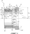
Fig. 2 is a perspective view of a casting and a housing of the engine ofFig. 1 in accordance with an embodiment; -
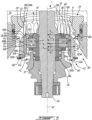
Fig. 3 is a cross-sectional view of a bearing assembly including the housing ofFig. 2 and taken along the line 3-3 ofFig. 2 ; -
Fig. 4 is a cross-sectional view of a housing and of a bearing outer race in accordance with another embodiment; -
Fig. 5 is a cross-sectional view of a housing and of a bearing outer race in accordance with another embodiment; and -
Fig. 6 is a perspective view of a housing and of a bearing outer race in accordance with another embodiment. -
Fig. 1 illustrates agas turbine engine 10 of a type preferably provided for use in subsonic flight, generally comprising in serial flow communication afan 12 through which ambient air is propelled, acentrifugal compressor 14 for pressurizing the air, acombustor 16 in which the compressed air is mixed with fuel and ignited for generating an annular stream of hot combustion gases, andturbines 18 for extracting energy from the combustion gases. A low-pressure turbine shaft 20 along a longitudinal axis A1 interconnects a low pressure turbine of theturbines 18 and thefan 12, whereas a high-pressure turbine shaft 22 also along the longitudinal axis A1 interconnects a high pressure turbine of theturbines 18 and thecompressor 14. Atower shaft 24 along a radial axis A2 interconnects the high-pressure turbine shaft 22 and anaccessory gearbox 26 of theengine 10. In use, pressurized air provided by thecompressor 14 through adiffuser 26 enters thecombustor 16 for combustion so as to drive theshafts turbines 18. Theshafts gas turbine engine 10 and more particularly a turbofan gas turbine engine, it shall be understood that the present disclosure is applicable to other types of machinery comprising bearing-supported rotatable components. - Referring to
Figs. 2 and3 , there is shown acasting 30 of theengine 10 with a bearing assembly 40 (Fig. 3 ) fitted thereto. Thecasting 30 defines a casting cavity Cc that may be described as a wet cavity as it is exposed to oil provided from an oil system of theengine 10. Thebearing assembly 40 generally includes ahousing 50 defining a bearing cavity Cb and abearing 60 fitted to thehousing 50 inside the bearing cavity Cb. The bearing cavity Cb is in fluid communication with the casting cavity Cc, such that thebearing 60 is exposed to oil having flowed from the casting cavity Cc and into the bearing cavity Cb. InFig. 2 , only thehousing 50 is shown, theshaft 24, thegear 28 and thebearing 60 having been removed in order to show the bearing cavity Cb in detail. - The
housing 50 will now be generally described with reference toFig. 2 . Thehousing 50 generally comprises an annular wall W extending circumferentially about the axis A2 and axially between opposite first andsecond housing ends first housing end 52 is spaced from thecasting 30, and defines an open side of the bearing cavity Cb via which thebearing 60 is received into the bearing cavity Cb. In this case, thefirst housing end 52 is free of any contact except with thebearing 60. Thesecond housing end 54 is fitted to a complementary portion of thecasting 30 so as to be constrained thereby. Thus, thehousing 50 is held by thecasting 30 at thesecond housing end 54. Stated otherwise, thehousing 50 and thecasting 30 are arranged relative to one another such that thecasting 30 opposes axial and radial displacements of thesecond housing end 54 which may otherwise occur under certain loading conditions of thehousing 50, for example loads exerted onto thehousing 50 via thebearing 60. Thesecond housing end 54 is affixed to thecasting 30 via welding, friction or other suitable means, whether directly or indirectly by way of an intermediate structure. In other embodiments, thehousing 50 and thecasting 30 form an integral piece, such that the annular wall W may be described as a projection of thecasting 30. Thehousing 50 also has aninterior housing surface 56 extending circumferentially about the axis A2 and axially between the first and second housing ends 52, 54. Proximate to thefirst housing end 52, theinterior housing surface 56 has acylindrical portion 56a that defines a seat 56b. The seat 56b defines a first housing radius Rh1 of thehousing 50 and circumscribes the bearing cavity Cb. The seat 56b is configured to radially engage thebearing 60, as will be described in greater detail below. Thecylindrical portion 56a of theinterior housing surface 56 extends axially from a first housing location Lh1 proximate to thefirst housing end 52 to at least a second housing location Lh2. Depending on the embodiment, first housing location Lh1 and the second housing location Lh2 may be said to axially delimit the seat 56b. Proximate to thesecond housing end 54, theinterior housing surface 56 defines a housing cavity in fluid communication between a casting cavity Cc of thecasting 30 and the bearing cavity Cb. The bearing cavity Cb may be said to be a portion of the housing cavity sized for receiving thebearing 60. Thehousing 50 also has anexterior housing surface 58 extending circumferentially about the axis A2 and axially between the first and second housing ends 52, 54. Proximate to thefirst housing end 52, theexterior housing surface 58 is cylindrical in shape, defines a second housing radius Rh2 of thehousing 50, and is disposed radially outward of theinterior housing surface 56. Hence, the second housing radius Rh2 is greater than the first housing radius Rh1. A difference between the second and first housing radii Rh2, Rh1 corresponds to a radial thickness Tr of thehousing 50. Proximate to thefirst housing end 52, the annular wall W may thus be said to be cylindrical in shape and to have the radial thickness Tr. - Proximate to the
second housing end 54, theexterior housing surface 58 is also cylindrical in shape, and yet defines a third housing radius Rh3 of thehousing 50 that is greater than the second housing radius Rh2. Indeed, as theexterior housing surface 58 extends away from thefirst housing end 52 and toward thesecond housing end 54, theexterior housing surface 58 transitions from the second housing radius Rh2 to the third housing radius Rh3 by way of ashoulder 58a. It is contemplated that in other embodiments, a shape of thehousing 50 may be different. For example, theexterior housing surface 58 could transition from the second housing radius Rh2 to the third housing radius Rh3 by way of a conical shape. In other embodiments, the annular wall W could be cylindrical in shape from thefirst housing end 52 to thesecond housing end 54. - In other embodiments, the
housing 50 can include additional structures located adjacent to the annular wall W at either one or both of thefirst housing end 52 and thesecond housing end 54. For instance, thehousing 50 may extend away from thecasting 30 to a location past thefirst housing end 52. In this embodiment, at thefirst housing end 52, thehousing 50 has a first housingaxial surface 52a extending circumferentially about the axis A2. A plurality ofkeyways 52b are defined in the first housingaxial surface 52a. Thekeyways 52b are circumferentially spaced from one another and extend radially through thehousing 50 from theexterior housing surface 58 to theinterior housing surface 56. The first housingaxial surface 52a may thus be said to be formed of sectors that are circumferentially spaced from one another by one of thekeyways 52b. - The annular wall W of the
housing 50 also defines a plurality of holes H that are spaced circumferentially from one another relative to the axis A2 and that extend through the annular wall W toward the axis A2, from theexterior housing surface 58 to theinterior housing surface 56. The holes H are thus in fluid communication with inside the bearing cavity Cb, and with inside the casting cavity Cc via the bearing cavity Cb. The holes H are spaced axially relative to thefirst housing end 52 so as to be proximate to a side of thebearing 60 that faces toward thesecond housing end 54 upon thebearing 60 being received by the bearing cavity Cb. In some embodiments, the holes H serve as drain ports, as they allow drainage of oil which would otherwise accumulate onto thebearing 60. The holes H are structured and arranged relative to the seat 56b so as to relieve stress exerted by thehousing 50 onto thebearing 60. Further characteristics of the holes H and their relationship with thebearing 60 will be discussed hereinbelow. - The bearing 60 will now be generally described with reference to
Fig. 3 . Thebearing 60 generally includes aninner race 70 extending circumferentially about the axis A2 and mounted to theshaft 24, a series ofrolling elements 80 disposed circumferentially about the axis A2 and around theinner race 70, anannular cage 90 shaped for maintaining each rolling element of the series ofrolling elements 80 in a suitable spatial relationship relative to one another, and anouter race 100 extending circumferentially about the axis A2 and around the series ofrolling elements 80. - The
inner race 70 includes a first inner-race end 72 and a second inner-race end 74 axially opposite to the first inner-race end 72. In this case, the first inner-race end 72 faces toward arecess 28a of agear 28 mounted to theshaft 24, and the second inner-race end faces toward ashoulder 24a of theshaft 24. Theinner race 70 also includes an interior inner-race surface 76 extending circumferentially about the axis A2 and axially between the first and second inner-race ends 72, 74. Theinner race 70 is mounted to theshaft 24 via the interior inner-race surface 76. Theinner race 70 also includes an exterior inner-race surface 78 shaped for interfacing with the series of rollingelements 80. In this embodiment, the exterior inner-race surface 78 defines a recess sized for receiving the series of rollingelements 80. - The
outer race 100 includes a first outer-race end 102 and a second outer-race end 104 opposite the first outer-race end 102. In this case, the first outer-race end 102 faces toward thegear 28, and the second outer-race end 104 faces toward the casting 30. Theouter race 100 also includes an interior outer-race surface 106 that extends circumferentially about the axis A2 and axially between the first and second outer-race ends 102, 104. The interior outer-race surface 106 defines a first outer-race radius Ro1 of theouter race 100 that is suitable for interfacing with the series of rollingelements 80. Theouter race 100 also includes an exterior outer-race surface 108 that extends circumferentially about the axis A2 and axially between the first and second outer-race ends 102, 104. The exterior outer-race surface 108 extends axially from afirst edge 108a to a second edge 108b. The exterior outer-race surface 108 defines a second outer-race radius Ro2 of theouter race 100 that is greater than the first outer-race radius Ro1, and is suitable for interfacing with thehousing 50. Indeed, the exterior outer-race surface 108 radially engages the seat 56b of theinterior housing surface 56. - In this embodiment, the first outer-
race end 102 is structured and arranged so as to engage thefirst housing end 52 upon theouter race 100 being mounted to thehousing 50 inside the bearing cavity Cb. At the first outer-race end 102, theouter race 100 includes a first outer-raceaxial surface 102a defining aflange 102b that extends radially to outward of the exterior outer-race surface 108. In this case, theflange 102b is circumferentially sectored, i.e., is formed of a plurality of radial projections, or keys, that are spaced circumferentially from one another. Each one of the keys is sized and arranged to be received by a corresponding one of thekeyways 52b. In other embodiments, thekeyways 52b are omitted, and theflange 102b engages the first housingaxial surface 52a. In other embodiments, theflange 102b is omitted, and the first outer-race end 102 does not engage thefirst housing end 52. - In this embodiment, the second outer-
race end 104 defines a second outer-raceaxial surface 104a. The second outer-race end 104 transitions from the second outer-raceaxial surface 104a to the interior outer-race surface 106 and to the exterior outer-race surface 108 by way of an inner transition surface 104b and anouter transition surface 104c respectively. In this embodiment, both transition surfaces 104b, 104c are tapering, or beveled, surfaces, although other shapes are contemplated. Depending on the embodiment, either one or both of the transition surfaces 104b, 104c may be omitted. - With reference to
Figs. 3 and4 , loading characteristics of the bearingassembly 40 will now be described. Theouter race 100 is mounted to thehousing 50 via the exterior outer-race surface 108, namely by a radial engagement between the exterior outer-race surface 108 and the seat 56b of theinterior housing surface 56. The second outer-race radius Ro2 is greater than the first housing radius Rh1, such that the second outer-race radius Ro2 and the first housing radius Rh1 may be said to define an interference fit. Upon theouter race 100 being mounted to thehousing 50, the exterior outer-race surface 108 overlaps the seat 56b of theinterior housing surface 56 as it extends away from thefirst housing end 52 toward thesecond housing end 54. In order to mount theouter race 100 to thehousing 50, theouter race 100 must be axially forced into the bearing cavity Cb, in this case via thefirst housing end 52. Theouter transition surface 104c may act as a wedge that assists in radially-inwardly compressing theouter race 100 as it is axially forced in the bearing cavity Cb. As thehousing 50 receives theouter race 100, thehousing 50 exerts loads onto theouter race 100 via theinterior housing surface 56, namely radially-inward compression (schematically shown at Fc) as well as axially-outward friction (schematically shown at Ff), i.e., friction that is directed opposite a direction of insertion of theouter race 100. Also, external support of the bearingassembly 40 is provided axisymmetrically and unilaterally (schematically shown at Fs) via the engagement of thesecond housing end 54 with the casting 30. In use, the above-mentioned loading conditions, coupled to loads exerted onto the bearing 60 via theinner race 70, lead to radial deformation of theouter race 100. Such deformation may be described as "coning", as the portion of theouter race 100 loaded by thehousing 50 collapses radially inwardly, and increasingly so as it extends into thehousing 50 toward thesecond housing end 54. Such deformation may be of a magnitude that is greater near the second outer-race end 104 for example at the second edge 108b of the exterior outer-race surface 108, than near the first outer-race end 102, for example at thefirst edge 108a. Thehousing 50 is provided with features, such as the plurality of holes H, that are sized and arranged for attenuating such deformation. The plurality of holes H locally reduce a stiffness of thehousing 50 at an axial location of thehousing 50 that is proximate to the second outer-race end 104 upon theouter race 100 being mounted to thehousing 50 so as to mitigate coning, i.e., to render the magnitude of any radial deformation of theouter race 100 similar from thefirst end 102 to thesecond end 104. - A first cross-sectional dimension D1 (
Fig. 2 ) of the holes H is defined circumferentially with respect to the axis A2, whereas a second cross-sectional dimension D2 (Fig. 3 ) of the holes H is defined perpendicularly to the first cross-sectional dimension D1. In this embodiment, the holes H are cylindrical, such that the first and second cross-sectional dimensions D1, D2 correspond to diameters of the hole H having a same length. The holes H extend toward the axis A2 at a skew angle Φ relative to the axis A2. Depending on the embodiment, the skew angle may be between 20 and 90 degrees. In some such embodiments, the skew angle Φ is between 25 and 70 degrees. In some such embodiments, the skew angle Φ is between 30 and 40 degrees. In this embodiment, the skew angle Φ is of about 35 degrees, and is acute toward thefirst housing end 52 such that the holes H extend axially away from thefirst housing end 52 as they extend radially toward the axis A2. Theexterior housing surface 58 and theinterior housing surface 56 respectively define exterior openings H1 and interior openings H2 of the holes H. In embodiments in which the skew angle Φ is acute toward thefirst housing end 52, each one of the holes H may be said to extend axially away from thesecond housing end 54 as it extends from their corresponding one of the interior openings H2 to their corresponding one of the exterior openings H1. This arrangement of the holes H may assist drainage of oil from the bearing cavity Cb via the holes H, and in some cases deflect oil and possible contaminants away from thebearing 60. The exterior openings H1 extend axially away from thefirst housing end 52 from a first exterior axial location Le1 to a second exterior axial location Le2. The interior openings H2 extend axially from a first interior axial location Li1 to a second interior axial location Li2. The second housing location Lh2 is located between the first housing location Lh1 and the interior openings H2. Depending on the embodiment, the second housing location Lh2 can be axially spaced from the first interior location Li1 (Fig. 3 ), and hence the seat 56b of theinterior housing surface 56 may stop short of the interior openings H2. In this embodiment, the interior openings H2 are defined in a groove 56c of thehousing 50 located axially between thecylindrical portion 56a and thesecond housing end 54. The second housing location Lh2 can otherwise correspond to the first interior location Li1 (Figs. 4 ,5 ), in which case thecylindrical portion 56a may be said to define at least a portion of the interior openings H2. In this embodiment, due to the acute aspect of the skew angle Φ, the first exterior axial location Le1 is closer to thefirst housing end 52 than the first interior axial location Li1. It should also be noted that the first exterior axial location Le1 is located axially between the first and thesecond edges 108a, 108b of the exterior outer-race surface 108. By this arrangement, the exterior openings H1 of the holes H overhang a portion of the seat 56b, and thus a portion of the exterior outer-race surface 108 via which the seat 56b of thehousing 50 radially engages theouter race 100, thereby locally reducing the ability of thehousing 50 to deform the underlying portion of theouter race 100. In this embodiment, theinterior housing surface 56 defines a radius that is greater than the first housing radius Rh1 at both the first and the second interior axial locations Li1, Li2. In this embodiment, the exterior openings H1 overlap theshoulder 58a, such that theexterior housing surface 58 defines the second housing radius Rh2 at the first exterior axial location Le1, and defines a radius that is greater than the second housing radius Rh2 at the second exterior axial location Le2. It should also be noted that at the first exterior location Le1, theinterior housing surface 56 defines the first housing radius Rh1, such that thehousing 50 has the radial thickness Tr at the first exterior location Le1. - In the embodiments of
Figs. 2 and3 , ofFig. 4 , ofFig. 5 and ofFig. 6 , thehousing 50 and theouter race 100 are arranged relative to one another such that the interior openings H2 of the holes H do not overlap the exterior outer-race surface 108. By this arrangement, the second edge 108b of the exterior outer-race surface 108 is fully circumscribed by the seat 56b of theinterior housing surface 56. This allows to minimize circumferential variation in the radial deformation of theouter race 100 proximate to the secondouter race end 104. In the embodiment ofFigs. 2 and3 , the first interior axial location Li1 is spaced axially away from thefirst housing end 52 such that the second edge 108b of the exterior outer-race surface 108 is located axially between thefirst edge 108a and the first interior axial location Li1. Stated otherwise, the exterior outer-race surface 108 extends axially toward the plurality of holes H from thefirst edge 108a located proximate to thefirst housing end 52 to the second edge 108b located proximate to the first interior axial location Li1. The exterior outer-race surface 108 also stops short of the interior openings H2, i.e., the second edge 108b of the exterior outer-race surface 108 is spaced axially from the first interior axial location Li1. The interior openings H2 of the holes H overlap a portion of the second outer-race end 104. Indeed, theouter transition surface 104c extends across the first interior axial location Li1 as it extends from the second edge 108b to the second outer-raceaxial surface 104a. It should be noted however that the portion of the second outer-race end 104 overlapped by the interior openings H2 is spaced radially inwardly from theinterior housing surface 56 and thus from the interior openings H2. -
Fig. 4 shows another embodiment of the bearingassembly 40. In this embodiment, thecylindrical portion 56a of theinterior housing surface 56 extends axially from the first housing location Lh1 to across the interior openings H2 toward thesecond housing end 54, and thus defines the interior openings H2. The seat 56b is adjacent to the interior openings H2 of the holes H at the first interior axial location Li1. The skew angle Φ of the holes H is acute toward thefirst housing end 52. Theexterior housing surface 58 defines the second housing radius Rh2 at the first exterior axial location Le1 and at the second exterior axial location Le2. Theinterior housing surface 56 defines the first housing radius Rh1 at the first interior axial location Li1 and at the second interior axial location Li2. The interior openings H2 of the holes H do not overlap the exterior outer-race surface 108 nor any other portion of theouter race 100. For instance, the second edge 108b of the exterior outer-race surface 108 and the second outer-race end 104 (in this case consisting of the second outer-raceaxial surface 104a) are at the first interior axial location Li1. -
Fig. 5 shows another embodiment of the bearingassembly 40. In this embodiment, thecylindrical portion 56a of theinterior housing surface 56 extends axially from the first housing location Lh1 to across the interior openings H2 toward thesecond housing end 54, and thus defines the interior openings H2. The seat 56b is adjacent to the interior openings H2 of the holes H at the first interior axial location Li1. The skew angle Φ of the holes H is acute toward thefirst housing end 52. Theexterior housing surface 58 defines the second housing radius Rh2 at the first exterior axial location Le1 and at the second exterior axial location Le2. Theinterior housing surface 56 defines the first housing radius Rh1 at the first interior axial location Li1 and at the second interior axial location Li2. The interior openings H2 of the holes H do not overlap the exterior outer-race surface 108. For instance, the second edge 108b of the exterior outer-race surface 108 is at the first interior axial location Li1. However, the interior openings H2 of the holes H do overlap the second outer-race end 104, as theouter transition surface 104c extends past the first interior axial location Li1 toward the second interior axial location Li2 as it extends from the second edge 108b to the second axial outer-race surface 104a. Also, theouter transition surface 104c tapers as it extends from the second edge 108b, such that it remains spaced radially inwardly from theinterior housing surface 56 and thus of the interior openings H2. -
Fig. 6 shows yet another embodiment of the bearingassembly 40. In this embodiment, the holes H extend radially relative to the axis A2, i.e., the skew angle Φ is a right angle. The holes H in this case have an elliptical cross-section, wherein the first cross-sectional dimension D1 is a length of a short axis thereof and the second cross-sectional dimension D2 is a length of a long axis thereof. - In embodiments such as those described hereinabove, the holes H are sized as a function of one or more dimensions of the
housing 50 proximate to the second outer-race end 104 so as to achieve adequate radial deformation of theouter race 100. For example, the first cross-sectional dimension D1 (Figs. 2 ,6 ) may be sized as a function of the radial thickness Tr of thehousing 50 at a rated axial location of thehousing 50. The rated axial location may be contiguous to the holes H on a side thereof that is proximate to thefirst housing end 52 and thus, in the depicted embodiments, corresponds to the first exterior location Le1. The rated location may be between the first housing location Lh1 and the first exterior location Le1. In embodiments, the first-cross-sectional dimension D1 is greater than the radial thickness Tr. In some such embodiments, the first cross-sectional dimension D1 is greater than 1.25 times the radial thickness Tr. In some such embodiments, the first cross-sectional dimension D1 is less than 1.75 times the radial thickness Tr. In some such embodiments, the first cross-sectional dimension D1 is between 1.35 and 1.55 times the radial thickness Tr. Moreover, the first cross-sectional dimension D1 may be sized as a function of a circumferential thickness Tc (Figs. 2 and6 ) of thehousing 50 defined between the holes H at theexterior housing surface 58, i.e., a minimum distance between two consecutive exterior openings H1. In embodiments, the first-cross-sectional dimension D1 is greater than the circumferential thickness Tc. In some such embodiments, the first cross-sectional dimension D1 is greater than 1.20 times the circumferential thickness Tc. In some such embodiments, the first cross-sectional dimension D1 is less than 1.60 times the circumferential thickness Tc. In some such embodiments, the first cross-sectional dimension D1 is between 1.30 and 1.50 times the circumferential thickness Tc. Hence, depending on the embodiment, the first cross-sectional dimension D1 may be at least equal to at least one of the radial thickness Tr of the annular wall W and the minimum distance between exterior openings H1 of consecutive holes of the plurality of holes H. - The embodiments described in this document provide non-limiting examples of possible implementations of the present technology. Upon review of the present disclosure, a person of ordinary skill in the art will recognize that changes may be made to the embodiments described herein without departing from the scope of the present technology. Yet further modifications could be implemented by a person of ordinary skill in the art in view of the present disclosure, which modifications would be within the scope of the present technology.
Claims (13)
- A bearing housing (50) for a bearing (60) having an outer race (100), the bearing housing (50) comprising:
an annular wall (W) extending about an axis (A2) and axially between a first end (52) and a second end (54), the annular wall (W) including:a plurality of holes (H) spaced circumferentially from one another and spaced axially from the first end (52), the plurality of holes (H) extending through the annular wall (W) toward the axis (A2); andan interior housing surface (56) extending about the axis (A2) and defining interior openings (H2) of the plurality of holes (H), the interior housing surface (56) having a cylindrical portion (56a) defining a seat (56b) for radial engagement with the outer race (100), the cylindrical portion (56a) extending axially from a first location (Lh1) proximate to the first end (52) to at least a second location (Lh2) between the first location (Lh1) and the interior openings (H2). - The bearing housing (50) of claim 1, wherein the cylindrical portion (56a) defines at least a portion of the interior openings (H2).
- The bearing housing (50) of claim 2, wherein the cylindrical portion (56a) defines the interior openings (H2), the cylindrical portion (56a) extending axially from the first location (Lh1) to across the interior openings (H2) toward the second end (54).
- The bearing housing (50) of any one of claims 1 to 3, wherein each hole of the plurality of holes (H) extends toward the axis (A2) at a skew angle (Φ) relative to the axis (A2), the skew angle (Φ) being acute toward the first end (52).
- The bearing housing (50) of claim 4, wherein the skew angle (Φ) is between 30 and 40 degrees.
- The bearing housing (50) of any one of claims 1 to 5, wherein each hole (H) of the plurality of holes (H) has a cross-sectional dimension (D1, D2) being at least equal to at least one of a radial thickness (Tr) of the annular wall (W) and a minimum distance between exterior openings (H1) of consecutive holes of the plurality of holes (H).
- The bearing housing (50) of claim 6, wherein the cross-sectional dimension (D1) is defined circumferentially relative to the axis (A2).
- The bearing housing (50) of claim 6 or 7, wherein the cross-sectional dimension (D1, D2) is at least equal to the radial thickness (Tr), the cross-sectional dimension (D1, D2) being between 1.35 and 1.55 times the radial thickness (Tr).
- The bearing housing (50) of any of claims 6 to 8, wherein the cross-sectional dimension (D1, D2) is at least equal to the minimum distance, the cross-sectional dimension (D1, D2) being between 1.30 and 1.50 times the minimum distance.
- A bearing assembly (40) comprising:a bearing housing (50) according to any one of the preceding claims,the interior housing surface (56) having a cylindrical portion (56a) circumscribing a bearing cavity (Cb); anda bearing (60) including an outer race (100) extending about the axis (A2) and axially between a first outer-race end (102) and a second outer-race end (104), the outer race (100) received by the housing (50) inside the bearing cavity (Cb) such that the first outer-race end (102) is proximate to the first housing end (52) and the second outer-race end (104) is proximate to the interior openings (H2).
- The bearing assembly (40) of claim 10, wherein the outer race (100) includes an exterior outer-race surface (108) extending circumferentially about the axis (A2) and axially between the first and second outer-race ends (102, 104), and the interior openings (H2) are located axially between the exterior outer-race surface (108) and the second housing end (54).
- The bearing assembly (40) of claim 11, wherein the second outer-race end (104) includes an outer transition surface (104c) adjacent to the exterior outer-race surface (108), the outer transition surface (104c) axially overlapping the interior openings (H2).
- A turbine engine (10) comprising:a casting (30) defining a wet cavity (Cc); anda bearing assembly (40) according to any one of claims 10 to 12, wherein the first end (102) of the annular wall (W) of the bearing housing (50) extends away from the casting (30), the second end (104) of the annular wall (W) extending proximate to the casting (30).
Applications Claiming Priority (1)
| Application Number | Priority Date | Filing Date | Title |
|---|---|---|---|
| US17/651,913 US11891906B2 (en) | 2022-02-22 | 2022-02-22 | Bearing housing |
Publications (2)
| Publication Number | Publication Date |
|---|---|
| EP4230888A1 true EP4230888A1 (en) | 2023-08-23 |
| EP4230888B1 EP4230888B1 (en) | 2025-07-09 |
Family
ID=85328776
Family Applications (1)
| Application Number | Title | Priority Date | Filing Date |
|---|---|---|---|
| EP23158074.7A Active EP4230888B1 (en) | 2022-02-22 | 2023-02-22 | Bearing housing |
Country Status (3)
| Country | Link |
|---|---|
| US (1) | US11891906B2 (en) |
| EP (1) | EP4230888B1 (en) |
| CA (1) | CA3190337A1 (en) |
Families Citing this family (2)
| Publication number | Priority date | Publication date | Assignee | Title |
|---|---|---|---|---|
| US20260092566A1 (en) * | 2024-09-30 | 2026-04-02 | Pratt & Whitney Canada Corp. | Gas Turbine Engine Tower Shaft with Narrowed Support Member |
| US20260092565A1 (en) * | 2024-09-30 | 2026-04-02 | Pratt & Whitney Canada Corp. | Gas Turbine Engine Tower Shaft Assembly |
Citations (2)
| Publication number | Priority date | Publication date | Assignee | Title |
|---|---|---|---|---|
| EP0042320A1 (en) * | 1980-06-13 | 1981-12-23 | Societe Nationale D'etude Et De Construction De Moteurs D'aviation, "S.N.E.C.M.A." | Oil-film damped bearing between shafts of a multi-spool turbomachine |
| EP3527838A1 (en) * | 2018-02-19 | 2019-08-21 | Pratt & Whitney Canada Corp. | Seal and bearing assembly with bearing outer portion comprising a seal static portion |
Family Cites Families (6)
| Publication number | Priority date | Publication date | Assignee | Title |
|---|---|---|---|---|
| ITTO20130745A1 (en) * | 2013-09-13 | 2015-03-14 | Skf Ab | CANNOTTO COSTAMPABILE WITH WASHING MACHINE TANKS |
| JP6117377B2 (en) | 2013-12-04 | 2017-04-19 | 三菱重工業株式会社 | Squeeze film damper, bearing unit and turbine |
| US9841056B2 (en) * | 2015-10-21 | 2017-12-12 | General Electric Company | Bearing with drained race and squeeze film damper |
| EP3239481A1 (en) * | 2016-04-27 | 2017-11-01 | Rolls-Royce plc | Oil chamber wall with through-holes |
| US10495144B1 (en) * | 2018-05-25 | 2019-12-03 | Borgwarner Inc. | Single-row ball bearing with integrated squeeze-film damper |
| US10662998B2 (en) | 2018-08-13 | 2020-05-26 | Schaeffler Technologies AG & Co, KG | Sleeve for deep groove ball bearing |
-
2022
- 2022-02-22 US US17/651,913 patent/US11891906B2/en active Active
-
2023
- 2023-02-20 CA CA3190337A patent/CA3190337A1/en active Pending
- 2023-02-22 EP EP23158074.7A patent/EP4230888B1/en active Active
Patent Citations (2)
| Publication number | Priority date | Publication date | Assignee | Title |
|---|---|---|---|---|
| EP0042320A1 (en) * | 1980-06-13 | 1981-12-23 | Societe Nationale D'etude Et De Construction De Moteurs D'aviation, "S.N.E.C.M.A." | Oil-film damped bearing between shafts of a multi-spool turbomachine |
| EP3527838A1 (en) * | 2018-02-19 | 2019-08-21 | Pratt & Whitney Canada Corp. | Seal and bearing assembly with bearing outer portion comprising a seal static portion |
Also Published As
| Publication number | Publication date |
|---|---|
| US11891906B2 (en) | 2024-02-06 |
| CA3190337A1 (en) | 2023-08-22 |
| EP4230888B1 (en) | 2025-07-09 |
| US20230265768A1 (en) | 2023-08-24 |
Similar Documents
| Publication | Publication Date | Title |
|---|---|---|
| US7269938B2 (en) | Counter-rotating gas turbine engine and method of assembling same | |
| EP3575620B1 (en) | Single-row ball bearing with integrated squeeze-film damper | |
| CN107044346B (en) | Bearing outer race retention during high load events | |
| EP4230888B1 (en) | Bearing housing | |
| US10851671B2 (en) | Bending stiffening feature used for compliant journal bearing | |
| US20170089220A1 (en) | Bearing housing and related bearing assembly for a gas turbine engine | |
| CN114555927B (en) | Turbomachine fan assembly including roller bearing and tilt-contact double row ball bearing | |
| CN110268174B (en) | Roller element bearing with preloaded hydrodynamic cage guide | |
| EP4095360B1 (en) | Stiffening strut for a turbine exit case | |
| US12460550B2 (en) | Fan module equipped with an oil transfer device | |
| US20200191055A1 (en) | Twin-spool turbojet engine having a low-pressure shaft thrust bearing positioned in the exhaust casing | |
| US20210254659A1 (en) | Dual land journal bearings for a compound planetary system | |
| US10125630B2 (en) | Fan disk for a jet engine and jet engine | |
| EP2136090B1 (en) | Radial ball bearing | |
| US12065976B2 (en) | Oil recovery device for a turbomachine | |
| EP1087101B1 (en) | Coupling assembly and method for connecting air ducts in gas turbine rotors | |
| US10138940B2 (en) | Roller bearing cage for use in a gearbox | |
| US8475116B2 (en) | Anti-rotation feature for air turbine starter | |
| EP3835606B1 (en) | Curved beam centering spring for a thrust bearing | |
| EP3647541B1 (en) | Split vernier ring for turbine rotor stack assembly | |
| EP4621192A2 (en) | Bearing oil distribution scheme | |
| US12510094B1 (en) | Coupling joints to interconnect and transmit rotational torque between adjacent impeller bodies in a turbomachine | |
| US11268405B2 (en) | Bearing support structure with variable stiffness | |
| CN116802405A (en) | Stator blade assembly for aircraft turbine engine compressor | |
| CA3109071A1 (en) | Dual land journal bearings for a compound planetary system |
Legal Events
| Date | Code | Title | Description |
|---|---|---|---|
| PUAI | Public reference made under article 153(3) epc to a published international application that has entered the european phase |
Free format text: ORIGINAL CODE: 0009012 |
|
| STAA | Information on the status of an ep patent application or granted ep patent |
Free format text: STATUS: THE APPLICATION HAS BEEN PUBLISHED |
|
| AK | Designated contracting states |
Kind code of ref document: A1 Designated state(s): AL AT BE BG CH CY CZ DE DK EE ES FI FR GB GR HR HU IE IS IT LI LT LU LV MC ME MK MT NL NO PL PT RO RS SE SI SK SM TR |
|
| STAA | Information on the status of an ep patent application or granted ep patent |
Free format text: STATUS: REQUEST FOR EXAMINATION WAS MADE |
|
| 17P | Request for examination filed |
Effective date: 20240223 |
|
| RBV | Designated contracting states (corrected) |
Designated state(s): AL AT BE BG CH CY CZ DE DK EE ES FI FR GB GR HR HU IE IS IT LI LT LU LV MC ME MK MT NL NO PL PT RO RS SE SI SK SM TR |
|
| GRAP | Despatch of communication of intention to grant a patent |
Free format text: ORIGINAL CODE: EPIDOSNIGR1 |
|
| STAA | Information on the status of an ep patent application or granted ep patent |
Free format text: STATUS: GRANT OF PATENT IS INTENDED |
|
| INTG | Intention to grant announced |
Effective date: 20250129 |
|
| GRAS | Grant fee paid |
Free format text: ORIGINAL CODE: EPIDOSNIGR3 |
|
| GRAA | (expected) grant |
Free format text: ORIGINAL CODE: 0009210 |
|
| STAA | Information on the status of an ep patent application or granted ep patent |
Free format text: STATUS: THE PATENT HAS BEEN GRANTED |
|
| AK | Designated contracting states |
Kind code of ref document: B1 Designated state(s): AL AT BE BG CH CY CZ DE DK EE ES FI FR GB GR HR HU IE IS IT LI LT LU LV MC ME MK MT NL NO PL PT RO RS SE SI SK SM TR |
|
| REG | Reference to a national code |
Ref country code: GB Ref legal event code: FG4D |
|
| REG | Reference to a national code |
Ref country code: CH Ref legal event code: EP |
|
| REG | Reference to a national code |
Ref country code: IE Ref legal event code: FG4D |
|
| REG | Reference to a national code |
Ref country code: DE Ref legal event code: R096 Ref document number: 602023004594 Country of ref document: DE |
|
| REG | Reference to a national code |
Ref country code: NL Ref legal event code: MP Effective date: 20250709 |
|
| PG25 | Lapsed in a contracting state [announced via postgrant information from national office to epo] |
Ref country code: PT Free format text: LAPSE BECAUSE OF FAILURE TO SUBMIT A TRANSLATION OF THE DESCRIPTION OR TO PAY THE FEE WITHIN THE PRESCRIBED TIME-LIMIT Effective date: 20251110 |
|
| PG25 | Lapsed in a contracting state [announced via postgrant information from national office to epo] |
Ref country code: NL Free format text: LAPSE BECAUSE OF FAILURE TO SUBMIT A TRANSLATION OF THE DESCRIPTION OR TO PAY THE FEE WITHIN THE PRESCRIBED TIME-LIMIT Effective date: 20250709 |
|
| REG | Reference to a national code |
Ref country code: AT Ref legal event code: MK05 Ref document number: 1812049 Country of ref document: AT Kind code of ref document: T Effective date: 20250709 |
|
| PG25 | Lapsed in a contracting state [announced via postgrant information from national office to epo] |
Ref country code: IS Free format text: LAPSE BECAUSE OF FAILURE TO SUBMIT A TRANSLATION OF THE DESCRIPTION OR TO PAY THE FEE WITHIN THE PRESCRIBED TIME-LIMIT Effective date: 20251109 |
|
| PG25 | Lapsed in a contracting state [announced via postgrant information from national office to epo] |
Ref country code: NO Free format text: LAPSE BECAUSE OF FAILURE TO SUBMIT A TRANSLATION OF THE DESCRIPTION OR TO PAY THE FEE WITHIN THE PRESCRIBED TIME-LIMIT Effective date: 20251009 |
|
| REG | Reference to a national code |
Ref country code: LT Ref legal event code: MG9D |
|
| PG25 | Lapsed in a contracting state [announced via postgrant information from national office to epo] |
Ref country code: AT Free format text: LAPSE BECAUSE OF FAILURE TO SUBMIT A TRANSLATION OF THE DESCRIPTION OR TO PAY THE FEE WITHIN THE PRESCRIBED TIME-LIMIT Effective date: 20250709 |
|
| PG25 | Lapsed in a contracting state [announced via postgrant information from national office to epo] |
Ref country code: FI Free format text: LAPSE BECAUSE OF FAILURE TO SUBMIT A TRANSLATION OF THE DESCRIPTION OR TO PAY THE FEE WITHIN THE PRESCRIBED TIME-LIMIT Effective date: 20250709 |
|
| PG25 | Lapsed in a contracting state [announced via postgrant information from national office to epo] |
Ref country code: HR Free format text: LAPSE BECAUSE OF FAILURE TO SUBMIT A TRANSLATION OF THE DESCRIPTION OR TO PAY THE FEE WITHIN THE PRESCRIBED TIME-LIMIT Effective date: 20250709 |
|
| PG25 | Lapsed in a contracting state [announced via postgrant information from national office to epo] |
Ref country code: GR Free format text: LAPSE BECAUSE OF FAILURE TO SUBMIT A TRANSLATION OF THE DESCRIPTION OR TO PAY THE FEE WITHIN THE PRESCRIBED TIME-LIMIT Effective date: 20251010 |
|
| PG25 | Lapsed in a contracting state [announced via postgrant information from national office to epo] |
Ref country code: SE Free format text: LAPSE BECAUSE OF FAILURE TO SUBMIT A TRANSLATION OF THE DESCRIPTION OR TO PAY THE FEE WITHIN THE PRESCRIBED TIME-LIMIT Effective date: 20250709 |
|
| PG25 | Lapsed in a contracting state [announced via postgrant information from national office to epo] |
Ref country code: LV Free format text: LAPSE BECAUSE OF FAILURE TO SUBMIT A TRANSLATION OF THE DESCRIPTION OR TO PAY THE FEE WITHIN THE PRESCRIBED TIME-LIMIT Effective date: 20250709 |
|
| PG25 | Lapsed in a contracting state [announced via postgrant information from national office to epo] |
Ref country code: BG Free format text: LAPSE BECAUSE OF FAILURE TO SUBMIT A TRANSLATION OF THE DESCRIPTION OR TO PAY THE FEE WITHIN THE PRESCRIBED TIME-LIMIT Effective date: 20250709 Ref country code: PL Free format text: LAPSE BECAUSE OF FAILURE TO SUBMIT A TRANSLATION OF THE DESCRIPTION OR TO PAY THE FEE WITHIN THE PRESCRIBED TIME-LIMIT Effective date: 20250709 |
|
| PG25 | Lapsed in a contracting state [announced via postgrant information from national office to epo] |
Ref country code: RS Free format text: LAPSE BECAUSE OF FAILURE TO SUBMIT A TRANSLATION OF THE DESCRIPTION OR TO PAY THE FEE WITHIN THE PRESCRIBED TIME-LIMIT Effective date: 20251009 |
|
| PG25 | Lapsed in a contracting state [announced via postgrant information from national office to epo] |
Ref country code: ES Free format text: LAPSE BECAUSE OF FAILURE TO SUBMIT A TRANSLATION OF THE DESCRIPTION OR TO PAY THE FEE WITHIN THE PRESCRIBED TIME-LIMIT Effective date: 20250709 |
|
| PG25 | Lapsed in a contracting state [announced via postgrant information from national office to epo] |
Ref country code: SM Free format text: LAPSE BECAUSE OF FAILURE TO SUBMIT A TRANSLATION OF THE DESCRIPTION OR TO PAY THE FEE WITHIN THE PRESCRIBED TIME-LIMIT Effective date: 20250709 |
|
| REG | Reference to a national code |
Ref country code: DE Ref legal event code: R097 Ref document number: 602023004594 Country of ref document: DE |
|
| PG25 | Lapsed in a contracting state [announced via postgrant information from national office to epo] |
Ref country code: DK Free format text: LAPSE BECAUSE OF FAILURE TO SUBMIT A TRANSLATION OF THE DESCRIPTION OR TO PAY THE FEE WITHIN THE PRESCRIBED TIME-LIMIT Effective date: 20250709 |
|
| PGFP | Annual fee paid to national office [announced via postgrant information from national office to epo] |
Ref country code: DE Payment date: 20260121 Year of fee payment: 4 |
|
| PGFP | Annual fee paid to national office [announced via postgrant information from national office to epo] |
Ref country code: IT Payment date: 20260228 Year of fee payment: 4 |
|
| PGFP | Annual fee paid to national office [announced via postgrant information from national office to epo] |
Ref country code: FR Payment date: 20260121 Year of fee payment: 4 |
|
| PG25 | Lapsed in a contracting state [announced via postgrant information from national office to epo] |
Ref country code: CZ Free format text: LAPSE BECAUSE OF FAILURE TO SUBMIT A TRANSLATION OF THE DESCRIPTION OR TO PAY THE FEE WITHIN THE PRESCRIBED TIME-LIMIT Effective date: 20250709 |
|
| PG25 | Lapsed in a contracting state [announced via postgrant information from national office to epo] |
Ref country code: SK Free format text: LAPSE BECAUSE OF FAILURE TO SUBMIT A TRANSLATION OF THE DESCRIPTION OR TO PAY THE FEE WITHIN THE PRESCRIBED TIME-LIMIT Effective date: 20250709 Ref country code: EE Free format text: LAPSE BECAUSE OF FAILURE TO SUBMIT A TRANSLATION OF THE DESCRIPTION OR TO PAY THE FEE WITHIN THE PRESCRIBED TIME-LIMIT Effective date: 20250709 |
|
| PLBE | No opposition filed within time limit |
Free format text: ORIGINAL CODE: 0009261 |
|
| STAA | Information on the status of an ep patent application or granted ep patent |
Free format text: STATUS: NO OPPOSITION FILED WITHIN TIME LIMIT |
|
| REG | Reference to a national code |
Ref country code: CH Ref legal event code: L10 Free format text: ST27 STATUS EVENT CODE: U-0-0-L10-L00 (AS PROVIDED BY THE NATIONAL OFFICE) Effective date: 20260521 |
|
| 26N | No opposition filed |
Effective date: 20260410 |
|
| PG25 | Lapsed in a contracting state [announced via postgrant information from national office to epo] |
Ref country code: LT Free format text: LAPSE BECAUSE OF FAILURE TO SUBMIT A TRANSLATION OF THE DESCRIPTION OR TO PAY THE FEE WITHIN THE PRESCRIBED TIME-LIMIT Effective date: 20250709 |