EP4230879A1 - Assembly for connecting a plastic part to a basic part - Google Patents
Assembly for connecting a plastic part to a basic part Download PDFInfo
- Publication number
- EP4230879A1 EP4230879A1 EP23156905.4A EP23156905A EP4230879A1 EP 4230879 A1 EP4230879 A1 EP 4230879A1 EP 23156905 A EP23156905 A EP 23156905A EP 4230879 A1 EP4230879 A1 EP 4230879A1
- Authority
- EP
- European Patent Office
- Prior art keywords
- plastic part
- cylindrical spacer
- groove
- assembly
- oval opening
- Prior art date
- Legal status (The legal status is an assumption and is not a legal conclusion. Google has not performed a legal analysis and makes no representation as to the accuracy of the status listed.)
- Granted
Links
Images

Classifications
-
- F—MECHANICAL ENGINEERING; LIGHTING; HEATING; WEAPONS; BLASTING
- F16—ENGINEERING ELEMENTS AND UNITS; GENERAL MEASURES FOR PRODUCING AND MAINTAINING EFFECTIVE FUNCTIONING OF MACHINES OR INSTALLATIONS; THERMAL INSULATION IN GENERAL
- F16B—DEVICES FOR FASTENING OR SECURING CONSTRUCTIONAL ELEMENTS OR MACHINE PARTS TOGETHER, e.g. NAILS, BOLTS, CIRCLIPS, CLAMPS, CLIPS OR WEDGES; JOINTS OR JOINTING
- F16B5/00—Joining sheets or plates, e.g. panels, to one another or to strips or bars parallel to them
- F16B5/02—Joining sheets or plates, e.g. panels, to one another or to strips or bars parallel to them by means of fastening members using screw-thread
- F16B5/0216—Joining sheets or plates, e.g. panels, to one another or to strips or bars parallel to them by means of fastening members using screw-thread the position of the plates to be connected being adjustable
- F16B5/0225—Joining sheets or plates, e.g. panels, to one another or to strips or bars parallel to them by means of fastening members using screw-thread the position of the plates to be connected being adjustable allowing for adjustment parallel to the plane of the plates
-
- B—PERFORMING OPERATIONS; TRANSPORTING
- B25—HAND TOOLS; PORTABLE POWER-DRIVEN TOOLS; MANIPULATORS
- B25B—TOOLS OR BENCH DEVICES NOT OTHERWISE PROVIDED FOR, FOR FASTENING, CONNECTING, DISENGAGING, OR HOLDING
- B25B27/00—Hand tools, specially adapted for fitting together or separating parts or objects whether or not involving some deformation, not otherwise provided for
- B25B27/14—Hand tools, specially adapted for fitting together or separating parts or objects whether or not involving some deformation, not otherwise provided for for assembling objects other than by press fit or detaching same
- B25B27/143—Hand tools, specially adapted for fitting together or separating parts or objects whether or not involving some deformation, not otherwise provided for for assembling objects other than by press fit or detaching same for installing wire thread inserts or tubular threaded inserts
-
- F—MECHANICAL ENGINEERING; LIGHTING; HEATING; WEAPONS; BLASTING
- F16—ENGINEERING ELEMENTS AND UNITS; GENERAL MEASURES FOR PRODUCING AND MAINTAINING EFFECTIVE FUNCTIONING OF MACHINES OR INSTALLATIONS; THERMAL INSULATION IN GENERAL
- F16B—DEVICES FOR FASTENING OR SECURING CONSTRUCTIONAL ELEMENTS OR MACHINE PARTS TOGETHER, e.g. NAILS, BOLTS, CIRCLIPS, CLAMPS, CLIPS OR WEDGES; JOINTS OR JOINTING
- F16B13/00—Dowels or other devices fastened in walls or the like by inserting them in holes made therein for that purpose
- F16B13/02—Dowels or other devices fastened in walls or the like by inserting them in holes made therein for that purpose in one piece with protrusions or ridges on the shaft
-
- F—MECHANICAL ENGINEERING; LIGHTING; HEATING; WEAPONS; BLASTING
- F16—ENGINEERING ELEMENTS AND UNITS; GENERAL MEASURES FOR PRODUCING AND MAINTAINING EFFECTIVE FUNCTIONING OF MACHINES OR INSTALLATIONS; THERMAL INSULATION IN GENERAL
- F16B—DEVICES FOR FASTENING OR SECURING CONSTRUCTIONAL ELEMENTS OR MACHINE PARTS TOGETHER, e.g. NAILS, BOLTS, CIRCLIPS, CLAMPS, CLIPS OR WEDGES; JOINTS OR JOINTING
- F16B37/00—Nuts or like thread-engaging members
- F16B37/12—Nuts or like thread-engaging members with thread-engaging surfaces formed by inserted coil-springs, discs, or the like; Independent pieces of wound wire used as nuts; Threaded inserts for holes
- F16B37/122—Threaded inserts, e.g. "rampa bolts"
- F16B37/125—Threaded inserts, e.g. "rampa bolts" the external surface of the insert being threaded
Definitions
- the invention relates to an assembly for connecting a plastic part to a basic part, typically a metal part, by means of a screw.
- the aim of the invention is to present a structurally simple assembly of components for connecting a plastic part to a basic part with sufficient screw fixation without deformation of the plastic part and to provide freedom in the relative positioning of multiple joints during assembly.
- an assembly for connecting a plastic part to a basic part according to the invention where the oval opening of the plastic part is provided with a projecting continuous circumferential projection and a cylindrical spacer is provided with a circumferential groove on its outer circumference, wherein the continuous circumferential projection is provided in the oval opening at a height corresponding to the position of the groove on the outer circumference of the cylindrical spacer.
- the width of the circumferential groove greater than the width of the continuous circumferential projection.
- the continuous circumferential projection arranged at half the height of the oval opening and the circumferential groove on the cylindrical spacer is arranged at half the height of the cylindrical spacer.
- cylindrical spacer with groove provided with a collar at the upper end.
- cylindrical spacer made of metal as formed or machined by lathe.
- Fig.1 shows a section through the screw joint of a plastic part to a basic part using a cylindrical spacer according to the state of the art
- Fig. 2 shows a section through the screw joint of a plastic part to a basic part using an oval spacer according to the state of the art
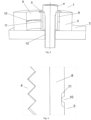
- Fig 3 shows a section through an assembly for connecting a plastic part to a basic part according to the invention
- Fig. 4 shows a detail of the connection of the circumferential groove on the spacer with the circumferential projection on the plastic part in section
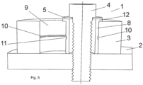
- Fig. 5 shows a section through an assembly for connecting a plastic part to a basic part according to the invention, where the spacer is provided with a collar.
- Fig. 3 shows a vertical section of the assembly 1 for connecting a plastic part 3 to a basic part 2 by means of a screw 4 with a washer 5.
- the joint consists of a cylindrical spacer 8 in the form of a tube provided with a groove 11 on its outer circumference, preferably made of metal, and machined by lathe or formed.
- the cylindrical spacer 8 with groove 11 is slidingly arranged in an oval opening 9 made in the plastic part 3.
- the cylindrical spacer 8 is provided with a groove 11 on its outer circumference, preferably in the middle of its height, and the plastic part 3 is in the oval opening 9 provided with a projecting continuous circumferential projection 10 on its inner circumference at a height corresponding to the position of the groove 11 on the cylindrical spacer 8.
- the resistance of the continuous circumferential projection 10 is overcome by pressure on the cylindrical spacer 8 with groove until it engages the groove 11 thereof.
- Fig. 4 shows in section a detail of the arrangement of the aforementioned groove 11 on the cylindrical spacer 8 and the continuous circumferential projection 10 provided in the oval opening 9 in the plastic part 3. It can be seen that the width of the groove 11 is greater than the width of the continuous circumferential projection 10, and the groove 11 extends with a slight clearance on both sides. This is to eliminate height inaccuracies in the production of the groove 11 on the cylindrical spacer 8 or the continuous circumferential projection 10 in the oval opening 9 in the plastic part 3. This allows the spacer 8 to be easily moved within the oval opening 9.
- the continuous circumferential projection 10 in the plastic part 3 is already provided when it is produced.
- a screw 4 is inserted into the cylindrical spacer 8 provided with the groove 11 and the screw 4 can move the cylindrical spacer 8 until the shank is accurately aligned with respect to the threaded opening 13 in the basic part 2.
- Fig. 5 shows a preferred embodiment of the cylindrical spacer 8 with the groove 11, wherein the oval opening 9 of the plastic part 3 with the continuous circumferential projection 10 is the same as in the previous embodiment, however, the cylindrical spacer 8 is provided with a collar 12 at the upper end. The upper face of the collar 12 then accommodates a washer 5.
Landscapes
- Engineering & Computer Science (AREA)
- General Engineering & Computer Science (AREA)
- Mechanical Engineering (AREA)
- Mutual Connection Of Rods And Tubes (AREA)
- Sewage (AREA)
- Lining Or Joining Of Plastics Or The Like (AREA)
- Forms Removed On Construction Sites Or Auxiliary Members Thereof (AREA)
- Centrifugal Separators (AREA)
Abstract
Description
- The invention relates to an assembly for connecting a plastic part to a basic part, typically a metal part, by means of a screw.
- In engineering practice, it is often necessary to connect a plastic part to a stronger, usually metal part, by means of a screw joint. An example of such an assembly, as connected according to the state of the art, is shown in vertical section in
Fig. 1 . Generally, there is a risk of deforming a plastic part when tightening the joint. This problem is solved by providing a plastic part, already when it is manufactured, with acylindrical spacer 6 fixed in its openings, as shown inFig. 1 . Nevertheless, if there are two screws, it is difficult to maintain the distance tolerances between the plastic part and the other part, so it is suitable to extend these tolerances. The plastic part is then fitted in its oval opening with anoval spacer 7, as shown inFig. 2 . This is to eliminate any inaccuracy in the relative position of two openings, so a longitudinal groove with anoval spacer 7 is used at the second type opening, thus enabling the assembler to position the joint correctly. This will reduce material degradation due to creep when the plastic part is compressed during screw tightening and damage of the plastic part. - The disadvantage of the oval spacer is the difficult and relatively expensive production and thus the price of the connection compared to the cylindrical spacer.
- The aim of the invention is to present a structurally simple assembly of components for connecting a plastic part to a basic part with sufficient screw fixation without deformation of the plastic part and to provide freedom in the relative positioning of multiple joints during assembly.
- The above mentioned deficiencies are eliminated by an assembly for connecting a plastic part to a basic part according to the invention, where the oval opening of the plastic part is provided with a projecting continuous circumferential projection and a cylindrical spacer is provided with a circumferential groove on its outer circumference, wherein the continuous circumferential projection is provided in the oval opening at a height corresponding to the position of the groove on the outer circumference of the cylindrical spacer.
- In a preferred embodiment is the width of the circumferential groove greater than the width of the continuous circumferential projection.
- In another preferred embodiment is the continuous circumferential projection arranged at half the height of the oval opening and the circumferential groove on the cylindrical spacer is arranged at half the height of the cylindrical spacer.
- In another preferred embodiment is the cylindrical spacer with groove provided with a collar at the upper end.
- In another preferred embodiment is the cylindrical spacer made of metal as formed or machined by lathe.
- The invention will be further described using drawings, where
Fig.1 shows a section through the screw joint of a plastic part to a basic part using a cylindrical spacer according to the state of the art,Fig. 2 shows a section through the screw joint of a plastic part to a basic part using an oval spacer according to the state of the art,Fig 3 shows a section through an assembly for connecting a plastic part to a basic part according to the invention,Fig. 4 shows a detail of the connection of the circumferential groove on the spacer with the circumferential projection on the plastic part in section, andFig. 5 shows a section through an assembly for connecting a plastic part to a basic part according to the invention, where the spacer is provided with a collar. -
Fig. 3 shows a vertical section of theassembly 1 for connecting aplastic part 3 to abasic part 2 by means of ascrew 4 with awasher 5. The joint consists of acylindrical spacer 8 in the form of a tube provided with agroove 11 on its outer circumference, preferably made of metal, and machined by lathe or formed. Thecylindrical spacer 8 withgroove 11 is slidingly arranged in anoval opening 9 made in theplastic part 3. Thecylindrical spacer 8 is provided with agroove 11 on its outer circumference, preferably in the middle of its height, and theplastic part 3 is in theoval opening 9 provided with a projecting continuouscircumferential projection 10 on its inner circumference at a height corresponding to the position of thegroove 11 on thecylindrical spacer 8. When assembled, the resistance of the continuouscircumferential projection 10 is overcome by pressure on thecylindrical spacer 8 with groove until it engages thegroove 11 thereof. -
Fig. 4 shows in section a detail of the arrangement of theaforementioned groove 11 on thecylindrical spacer 8 and the continuouscircumferential projection 10 provided in theoval opening 9 in theplastic part 3. It can be seen that the width of thegroove 11 is greater than the width of the continuouscircumferential projection 10, and thegroove 11 extends with a slight clearance on both sides. This is to eliminate height inaccuracies in the production of thegroove 11 on thecylindrical spacer 8 or the continuouscircumferential projection 10 in theoval opening 9 in theplastic part 3. This allows thespacer 8 to be easily moved within theoval opening 9. The continuouscircumferential projection 10 in theplastic part 3 is already provided when it is produced. - A
screw 4 is inserted into thecylindrical spacer 8 provided with thegroove 11 and thescrew 4 can move thecylindrical spacer 8 until the shank is accurately aligned with respect to the threadedopening 13 in thebasic part 2. -
Fig. 5 shows a preferred embodiment of thecylindrical spacer 8 with thegroove 11, wherein theoval opening 9 of theplastic part 3 with the continuouscircumferential projection 10 is the same as in the previous embodiment, however, thecylindrical spacer 8 is provided with acollar 12 at the upper end. The upper face of thecollar 12 then accommodates awasher 5.
Claims (5)
- Assembly for connecting a plastic part to a basic part by means of a screw, where an oval opening is made in the plastic part to allow the screw to be positioned against a threaded opening in the basic part, characterized in that the oval opening (9) of the plastic part (3) is provided with a projecting continuous circumferential projection (10) and a cylindrical spacer (8) is provided with a circumferential groove (11) on its outer circumference, wherein the continuous circumferential projection (10) is provided in the oval opening (9) at a height corresponding to the position of the groove (11) on the outer circumference of the cylindrical spacer (8).
- Assembly according to claim 1, characterized in that the width of the circumferential groove (11) is greater than the width of the continuous circumferential projection (10).
- Assembly of claim 1, characterized in that the continuous circumferential projection (10) is arranged at half the height of the oval opening (9) and the circumferential groove (11) on the cylindrical spacer (8) is arranged at half the height of the cylindrical spacer (8).
- Assembly according to claim 1, characterized in that the cylindrical spacer (8) with groove (11) is provided with a collar (12) at the upper end.
- Assembly according to claim 1, characterized in that the cylindrical spacer (8) is made of metal as formed or machined by lathe.
Applications Claiming Priority (1)
| Application Number | Priority Date | Filing Date | Title |
|---|---|---|---|
| CZ2022-81A CZ202281A3 (en) | 2022-02-22 | 2022-02-22 | Assembly for connecting the plastic part to the base part |
Publications (3)
| Publication Number | Publication Date |
|---|---|
| EP4230879A1 true EP4230879A1 (en) | 2023-08-23 |
| EP4230879C0 EP4230879C0 (en) | 2025-02-19 |
| EP4230879B1 EP4230879B1 (en) | 2025-02-19 |
Family
ID=83997715
Family Applications (1)
| Application Number | Title | Priority Date | Filing Date |
|---|---|---|---|
| EP23156905.4A Active EP4230879B1 (en) | 2022-02-22 | 2023-02-15 | Assembly for connecting a plastic part to a basic part |
Country Status (5)
| Country | Link |
|---|---|
| EP (1) | EP4230879B1 (en) |
| CZ (1) | CZ202281A3 (en) |
| ES (1) | ES3031690T3 (en) |
| HU (1) | HUE071761T2 (en) |
| PL (1) | PL4230879T3 (en) |
Citations (4)
| Publication number | Priority date | Publication date | Assignee | Title |
|---|---|---|---|---|
| EP1213186B1 (en) * | 2000-12-07 | 2008-01-09 | Bayerische Motoren Werke Aktiengesellschaft | Device for attaching two parts together |
| CN201613517U (en) * | 2010-01-18 | 2010-10-27 | 成都飞机工业(集团)有限责任公司 | Self-compensating and positioning device of assembly fixture |
| US20150075496A1 (en) * | 2013-09-18 | 2015-03-19 | Continental Automotive Gmbh | Fastening Assembly For A Fuel Rail Of A Combustion Engine |
| EP3070343B1 (en) * | 2015-03-16 | 2021-05-12 | Hellermanntyton | Device intended for being stationary including a portion with an opening and a metal band attached to said opening |
Family Cites Families (5)
| Publication number | Priority date | Publication date | Assignee | Title |
|---|---|---|---|---|
| JPH11325028A (en) * | 1998-05-13 | 1999-11-26 | Sigma Kk | Buried bush |
| US6692207B1 (en) * | 2002-09-05 | 2004-02-17 | Yardley Products Corp. | One-piece metallic threaded insert |
| JP3103899U (en) * | 2004-03-10 | 2004-08-26 | 株式会社アドバネクス | Insert collar |
| DE102009051037A1 (en) * | 2009-10-28 | 2011-09-15 | Audi Ag | Plastic-metal composite component has flat metal insert part with lower surface side and upper surface side, where threaded insert stands on lower surface side of metal insert part |
| JP2013044341A (en) * | 2011-08-22 | 2013-03-04 | Yazaki Corp | Metal member and resin product with the same |
-
2022
- 2022-02-22 CZ CZ2022-81A patent/CZ202281A3/en unknown
-
2023
- 2023-02-15 PL PL23156905.4T patent/PL4230879T3/en unknown
- 2023-02-15 EP EP23156905.4A patent/EP4230879B1/en active Active
- 2023-02-15 HU HUE23156905A patent/HUE071761T2/en unknown
- 2023-02-15 ES ES23156905T patent/ES3031690T3/en active Active
Patent Citations (4)
| Publication number | Priority date | Publication date | Assignee | Title |
|---|---|---|---|---|
| EP1213186B1 (en) * | 2000-12-07 | 2008-01-09 | Bayerische Motoren Werke Aktiengesellschaft | Device for attaching two parts together |
| CN201613517U (en) * | 2010-01-18 | 2010-10-27 | 成都飞机工业(集团)有限责任公司 | Self-compensating and positioning device of assembly fixture |
| US20150075496A1 (en) * | 2013-09-18 | 2015-03-19 | Continental Automotive Gmbh | Fastening Assembly For A Fuel Rail Of A Combustion Engine |
| EP3070343B1 (en) * | 2015-03-16 | 2021-05-12 | Hellermanntyton | Device intended for being stationary including a portion with an opening and a metal band attached to said opening |
Also Published As
| Publication number | Publication date |
|---|---|
| ES3031690T3 (en) | 2025-07-10 |
| HUE071761T2 (en) | 2025-09-28 |
| CZ309398B6 (en) | 2022-11-16 |
| EP4230879C0 (en) | 2025-02-19 |
| CZ202281A3 (en) | 2022-11-16 |
| PL4230879T3 (en) | 2025-06-09 |
| EP4230879B1 (en) | 2025-02-19 |
Similar Documents
| Publication | Publication Date | Title |
|---|---|---|
| EP0213505B1 (en) | Pipe coupling | |
| US6193239B1 (en) | Tube joint | |
| US5478122A (en) | Rotatable connector joint | |
| US3833984A (en) | Process and arrangement for double flanging of pipes | |
| US4529231A (en) | Flat-face tube connector | |
| KR960006175B1 (en) | Special male and female threads for compressed air systems | |
| JP2811233B2 (en) | Pipe fittings | |
| US20180320804A1 (en) | Conduit fitting with components adapted for facilitating assembly | |
| US5056704A (en) | Tube fitting having a saddle bead with conforming pilot | |
| US4230349A (en) | Joint | |
| JP2558726Y2 (en) | Pipe joint structure | |
| WO1997007356A1 (en) | High-pressure connection system | |
| EP0423156B1 (en) | Working cylinder | |
| US5215335A (en) | Fitting for pressurized fluid lines and method for making same | |
| DE60305849T2 (en) | Pipe coupling, coupling method and die | |
| US20020043805A1 (en) | Connection of a micro-tube to a structure | |
| EP2112414A1 (en) | Housing-shaped pipe joint | |
| EP4230879A1 (en) | Assembly for connecting a plastic part to a basic part | |
| JP2005257065A (en) | Hose fittings | |
| US20160169432A1 (en) | Hydraulic cylinder joint and hydraulic cylinder pipe including same | |
| DE10248986A1 (en) | Pipe joint assembly has annular claw which extends outwardly from joint block and crimped over flange in each pipe so that engaging recesses of joining block are engaged with flange of each pipe | |
| CN1717562A (en) | Hydraulic hose fitting and method | |
| WO1993024780A1 (en) | Multiple-piece externally swagable fitting | |
| EP2334967B1 (en) | Two-part composite fitting | |
| SK120896A3 (en) | Apparatus for attachment of pipes |
Legal Events
| Date | Code | Title | Description |
|---|---|---|---|
| PUAI | Public reference made under article 153(3) epc to a published international application that has entered the european phase |
Free format text: ORIGINAL CODE: 0009012 |
|
| STAA | Information on the status of an ep patent application or granted ep patent |
Free format text: STATUS: THE APPLICATION HAS BEEN PUBLISHED |
|
| AK | Designated contracting states |
Kind code of ref document: A1 Designated state(s): AL AT BE BG CH CY CZ DE DK EE ES FI FR GB GR HR HU IE IS IT LI LT LU LV MC ME MK MT NL NO PL PT RO RS SE SI SK SM TR |
|
| STAA | Information on the status of an ep patent application or granted ep patent |
Free format text: STATUS: REQUEST FOR EXAMINATION WAS MADE |
|
| 17P | Request for examination filed |
Effective date: 20231212 |
|
| GRAP | Despatch of communication of intention to grant a patent |
Free format text: ORIGINAL CODE: EPIDOSNIGR1 |
|
| STAA | Information on the status of an ep patent application or granted ep patent |
Free format text: STATUS: GRANT OF PATENT IS INTENDED |
|
| INTG | Intention to grant announced |
Effective date: 20241105 |
|
| GRAS | Grant fee paid |
Free format text: ORIGINAL CODE: EPIDOSNIGR3 |
|
| GRAA | (expected) grant |
Free format text: ORIGINAL CODE: 0009210 |
|
| STAA | Information on the status of an ep patent application or granted ep patent |
Free format text: STATUS: THE PATENT HAS BEEN GRANTED |
|
| AK | Designated contracting states |
Kind code of ref document: B1 Designated state(s): AL AT BE BG CH CY CZ DE DK EE ES FI FR GB GR HR HU IE IS IT LI LT LU LV MC ME MK MT NL NO PL PT RO RS SE SI SK SM TR |
|
| REG | Reference to a national code |
Ref country code: GB Ref legal event code: FG4D |
|
| REG | Reference to a national code |
Ref country code: CH Ref legal event code: EP |
|
| REG | Reference to a national code |
Ref country code: IE Ref legal event code: FG4D |
|
| REG | Reference to a national code |
Ref country code: DE Ref legal event code: R096 Ref document number: 602023002045 Country of ref document: DE |
|
| U01 | Request for unitary effect filed |
Effective date: 20250304 |
|
| U07 | Unitary effect registered |
Designated state(s): AT BE BG DE DK EE FI FR IT LT LU LV MT NL PT RO SE SI Effective date: 20250312 |
|
| REG | Reference to a national code |
Ref country code: SK Ref legal event code: T3 Ref document number: E 46316 Country of ref document: SK |
|
| PG25 | Lapsed in a contracting state [announced via postgrant information from national office to epo] |
Ref country code: RS Free format text: LAPSE BECAUSE OF FAILURE TO SUBMIT A TRANSLATION OF THE DESCRIPTION OR TO PAY THE FEE WITHIN THE PRESCRIBED TIME-LIMIT Effective date: 20250519 |
|
| REG | Reference to a national code |
Ref country code: ES Ref legal event code: FG2A Ref document number: 3031690 Country of ref document: ES Kind code of ref document: T3 Effective date: 20250710 |
|
| PG25 | Lapsed in a contracting state [announced via postgrant information from national office to epo] |
Ref country code: IS Free format text: LAPSE BECAUSE OF FAILURE TO SUBMIT A TRANSLATION OF THE DESCRIPTION OR TO PAY THE FEE WITHIN THE PRESCRIBED TIME-LIMIT Effective date: 20250619 Ref country code: NO Free format text: LAPSE BECAUSE OF FAILURE TO SUBMIT A TRANSLATION OF THE DESCRIPTION OR TO PAY THE FEE WITHIN THE PRESCRIBED TIME-LIMIT Effective date: 20250519 |
|
| PG25 | Lapsed in a contracting state [announced via postgrant information from national office to epo] |
Ref country code: HR Free format text: LAPSE BECAUSE OF FAILURE TO SUBMIT A TRANSLATION OF THE DESCRIPTION OR TO PAY THE FEE WITHIN THE PRESCRIBED TIME-LIMIT Effective date: 20250219 |
|
| PG25 | Lapsed in a contracting state [announced via postgrant information from national office to epo] |
Ref country code: GR Free format text: LAPSE BECAUSE OF FAILURE TO SUBMIT A TRANSLATION OF THE DESCRIPTION OR TO PAY THE FEE WITHIN THE PRESCRIBED TIME-LIMIT Effective date: 20250520 |
|
| REG | Reference to a national code |
Ref country code: HU Ref legal event code: AG4A Ref document number: E071761 Country of ref document: HU |
|
| PG25 | Lapsed in a contracting state [announced via postgrant information from national office to epo] |
Ref country code: SM Free format text: LAPSE BECAUSE OF FAILURE TO SUBMIT A TRANSLATION OF THE DESCRIPTION OR TO PAY THE FEE WITHIN THE PRESCRIBED TIME-LIMIT Effective date: 20250219 |
|
| PG25 | Lapsed in a contracting state [announced via postgrant information from national office to epo] |
Ref country code: CZ Free format text: LAPSE BECAUSE OF FAILURE TO SUBMIT A TRANSLATION OF THE DESCRIPTION OR TO PAY THE FEE WITHIN THE PRESCRIBED TIME-LIMIT Effective date: 20250219 |
|
| PLBE | No opposition filed within time limit |
Free format text: ORIGINAL CODE: 0009261 |
|
| STAA | Information on the status of an ep patent application or granted ep patent |
Free format text: STATUS: NO OPPOSITION FILED WITHIN TIME LIMIT |
|
| REG | Reference to a national code |
Ref country code: CH Ref legal event code: L10 Free format text: ST27 STATUS EVENT CODE: U-0-0-L10-L00 (AS PROVIDED BY THE NATIONAL OFFICE) Effective date: 20251231 |
|
| 26N | No opposition filed |
Effective date: 20251120 |
|
| U20 | Renewal fee for the european patent with unitary effect paid |
Year of fee payment: 4 Effective date: 20260108 |
|
| REG | Reference to a national code |
Ref country code: CH Ref legal event code: U11 Free format text: ST27 STATUS EVENT CODE: U-0-0-U10-U11 (AS PROVIDED BY THE NATIONAL OFFICE) Effective date: 20260301 |
|
| PGFP | Annual fee paid to national office [announced via postgrant information from national office to epo] |
Ref country code: HU Payment date: 20260212 Year of fee payment: 4 |
|
| PGFP | Annual fee paid to national office [announced via postgrant information from national office to epo] |
Ref country code: ES Payment date: 20260319 Year of fee payment: 4 |
|
| PGFP | Annual fee paid to national office [announced via postgrant information from national office to epo] |
Ref country code: CH Payment date: 20260301 Year of fee payment: 4 |
|
| PGFP | Annual fee paid to national office [announced via postgrant information from national office to epo] |
Ref country code: PL Payment date: 20260108 Year of fee payment: 4 |
|
| PGFP | Annual fee paid to national office [announced via postgrant information from national office to epo] |
Ref country code: SK Payment date: 20260109 Year of fee payment: 4 |