EP4230866A1 - Compressor anti-collision structure and electrical apparatus - Google Patents
Compressor anti-collision structure and electrical apparatus Download PDFInfo
- Publication number
- EP4230866A1 EP4230866A1 EP21885216.8A EP21885216A EP4230866A1 EP 4230866 A1 EP4230866 A1 EP 4230866A1 EP 21885216 A EP21885216 A EP 21885216A EP 4230866 A1 EP4230866 A1 EP 4230866A1
- Authority
- EP
- European Patent Office
- Prior art keywords
- compressor
- cushion pad
- hole
- strip
- chassis
- Prior art date
- Legal status (The legal status is an assumption and is not a legal conclusion. Google has not performed a legal analysis and makes no representation as to the accuracy of the status listed.)
- Granted
Links
Images







Classifications
-
- F—MECHANICAL ENGINEERING; LIGHTING; HEATING; WEAPONS; BLASTING
- F16—ENGINEERING ELEMENTS AND UNITS; GENERAL MEASURES FOR PRODUCING AND MAINTAINING EFFECTIVE FUNCTIONING OF MACHINES OR INSTALLATIONS; THERMAL INSULATION IN GENERAL
- F16M—FRAMES, CASINGS OR BEDS OF ENGINES, MACHINES OR APPARATUS, NOT SPECIFIC TO ENGINES, MACHINES OR APPARATUS PROVIDED FOR ELSEWHERE; STANDS; SUPPORTS
- F16M11/00—Stands or trestles as supports for apparatus or articles placed thereon ; Stands for scientific apparatus such as gravitational force meters
- F16M11/20—Undercarriages with or without wheels
- F16M11/22—Undercarriages with or without wheels with approximately constant height, e.g. with constant length of column or of legs
-
- F—MECHANICAL ENGINEERING; LIGHTING; HEATING; WEAPONS; BLASTING
- F04—POSITIVE - DISPLACEMENT MACHINES FOR LIQUIDS; PUMPS FOR LIQUIDS OR ELASTIC FLUIDS
- F04B—POSITIVE-DISPLACEMENT MACHINES FOR LIQUIDS; PUMPS
- F04B39/00—Component parts, details, or accessories, of pumps or pumping systems specially adapted for elastic fluids, not otherwise provided for in, or of interest apart from, groups F04B25/00 - F04B37/00
-
- F—MECHANICAL ENGINEERING; LIGHTING; HEATING; WEAPONS; BLASTING
- F04—POSITIVE - DISPLACEMENT MACHINES FOR LIQUIDS; PUMPS FOR LIQUIDS OR ELASTIC FLUIDS
- F04B—POSITIVE-DISPLACEMENT MACHINES FOR LIQUIDS; PUMPS
- F04B39/00—Component parts, details, or accessories, of pumps or pumping systems specially adapted for elastic fluids, not otherwise provided for in, or of interest apart from, groups F04B25/00 - F04B37/00
- F04B39/0027—Pulsation and noise damping means
-
- F—MECHANICAL ENGINEERING; LIGHTING; HEATING; WEAPONS; BLASTING
- F04—POSITIVE - DISPLACEMENT MACHINES FOR LIQUIDS; PUMPS FOR LIQUIDS OR ELASTIC FLUIDS
- F04B—POSITIVE-DISPLACEMENT MACHINES FOR LIQUIDS; PUMPS
- F04B39/00—Component parts, details, or accessories, of pumps or pumping systems specially adapted for elastic fluids, not otherwise provided for in, or of interest apart from, groups F04B25/00 - F04B37/00
- F04B39/0027—Pulsation and noise damping means
- F04B39/0044—Pulsation and noise damping means with vibration damping supports
-
- F—MECHANICAL ENGINEERING; LIGHTING; HEATING; WEAPONS; BLASTING
- F04—POSITIVE - DISPLACEMENT MACHINES FOR LIQUIDS; PUMPS FOR LIQUIDS OR ELASTIC FLUIDS
- F04B—POSITIVE-DISPLACEMENT MACHINES FOR LIQUIDS; PUMPS
- F04B39/00—Component parts, details, or accessories, of pumps or pumping systems specially adapted for elastic fluids, not otherwise provided for in, or of interest apart from, groups F04B25/00 - F04B37/00
- F04B39/12—Casings; Cylinders; Cylinder heads; Fluid connections
- F04B39/121—Casings
-
- F—MECHANICAL ENGINEERING; LIGHTING; HEATING; WEAPONS; BLASTING
- F04—POSITIVE - DISPLACEMENT MACHINES FOR LIQUIDS; PUMPS FOR LIQUIDS OR ELASTIC FLUIDS
- F04B—POSITIVE-DISPLACEMENT MACHINES FOR LIQUIDS; PUMPS
- F04B39/00—Component parts, details, or accessories, of pumps or pumping systems specially adapted for elastic fluids, not otherwise provided for in, or of interest apart from, groups F04B25/00 - F04B37/00
- F04B39/12—Casings; Cylinders; Cylinder heads; Fluid connections
- F04B39/127—Mounting of a cylinder block in a casing
-
- F—MECHANICAL ENGINEERING; LIGHTING; HEATING; WEAPONS; BLASTING
- F16—ENGINEERING ELEMENTS AND UNITS; GENERAL MEASURES FOR PRODUCING AND MAINTAINING EFFECTIVE FUNCTIONING OF MACHINES OR INSTALLATIONS; THERMAL INSULATION IN GENERAL
- F16F—SPRINGS; SHOCK-ABSORBERS; MEANS FOR DAMPING VIBRATION
- F16F1/00—Springs
- F16F1/36—Springs made of rubber or other material having high internal friction, e.g. thermoplastic elastomers
- F16F1/373—Springs made of rubber or other material having high internal friction, e.g. thermoplastic elastomers characterised by having a particular shape
- F16F1/3732—Springs made of rubber or other material having high internal friction, e.g. thermoplastic elastomers characterised by having a particular shape having an annular or the like shape, e.g. grommet-type resilient mountings
-
- F—MECHANICAL ENGINEERING; LIGHTING; HEATING; WEAPONS; BLASTING
- F16—ENGINEERING ELEMENTS AND UNITS; GENERAL MEASURES FOR PRODUCING AND MAINTAINING EFFECTIVE FUNCTIONING OF MACHINES OR INSTALLATIONS; THERMAL INSULATION IN GENERAL
- F16M—FRAMES, CASINGS OR BEDS OF ENGINES, MACHINES OR APPARATUS, NOT SPECIFIC TO ENGINES, MACHINES OR APPARATUS PROVIDED FOR ELSEWHERE; STANDS; SUPPORTS
- F16M1/00—Frames or casings of engines, machines or apparatus; Frames serving as machinery beds
Definitions
- the present disclosure relates to the technical field of electrical devices, in particular to a compressor anticollision structure and an electrical device.
- Electrical device such as air conditioner outdoor unit and dehumidifier
- a compressor is usually provided with a compressor. But as the product is designed to be more and more compact, the spatial structure around the compressor is excessively compressed, resulting in a relatively small distance between the compressor and external components and/or other internal components of the electrical device. In some cases, such as when the electrical device shakes violently or falls down during transportation, the compressor is likely to hit the external components and/or other internal components, resulting in damage to the external components and/or other internal components.
- the main objective of embodiments in the present disclosure is to provide a compressor anticollision structure and an electrical device with good anticollision effects.
- a compressor anticollision structure for an electrical device including:
- the anticollision strip includes a strip-shaped force-bearing body
- the support assembly includes a middle partition provided at the chassis, and the anticollision strip includes the strip-shaped force-bearing body, and two opposite ends in a length direction of the strip-shaped force-bearing body are fastened to the middle partition.
- the anticollision strip further includes at least two first positioning members, and each of the two opposite ends in the length direction of the strip-shaped force-bearing body is provided with at least one of the two first positioning members,
- the support assembly includes a middle partition provided at the chassis, and the middle partition includes a plate body and at least one enhanced boss protruding from a side of the plate body away from the compressor, the plate body is provided at the chassis, and the enhanced boss extends along a height direction of the plate body.
- the middle partition includes a first portion and a second portion along a height direction of the middle partition, the second portion is provided at a top side of the first portion, a continuous stepped surface is formed in a junction between a side of the first portion away from the compressor and a side of the second portion away from the compressor, the continuous stepped surface extends along a lateral direction of the middle partition and departs from the chassis, and a part of the enhanced boss is provided at the first portion of the middle partition, and another part of the enhanced boss is provided at the second portion of the middle partition.
- the compressor assembly further includes a support plate at a bottom of the compressor,
- the fixation assembly further includes a gasket and a nut threadedly connected to the support pillar,
- a minimum distance H1 between the cushion pad and the gasket is 0.5mm to 3mm along an axial direction of the support pillar.
- the nut and the gasket are separated and fastened to each other; or the nut and the gasket are integrated.
- the gasket comprises a folded edge folding towards the chassis, and an accommodation space is enclosed by the folded edge,
- a stepped hole is formed at the chassis, the stepped hole includes an installation sub-hole and a non-circular sub-hole at a bottom side of the installation sub-hole,
- the rod body includes a knurling section, a bare section, and a thread section,
- the stepped hole passes through the chassis, and the bolt member passes from a bottom side of the chassis into the stepped hole.
- the lock member is spaced apart from the cushion pad along an axial direction of the bolt member, to make the cushion pad have a free movement stroke along an axial direction of the cushion pad.
- the lock member includes a nut and a gasket
- the cushion pad includes a first axis hole and a second axis hole communicating with each other,
- the compressor anticollision structure further includes a surrounding plate, the surrounding plate protrudes from a top surface of the chassis and surrounds the installation sub-hole to enclose a limiting space communicating with the installation sub-hole, and a bottom of the cushion pad is located in the limiting space.
- the present disclosure further provides an electrical device, including any one of a compressor anticollision structures as mentioned above.
- Embodiments of the present disclosure provides a compressor anticollision structure.
- the anticollision strip can prevent the compressor from hitting the external components and/or other internal components of the electrical device.
- the probability of the compressor hitting the external components and/or other internal components of the electrical device can be greatly reduced, which can improve the product quality of the electrical device.
- the compressor anticollision structure includes a support assembly 10, a compressor assembly 20, and an anticollision strip 30.
- the support assembly 10 includes a chassis 11.
- the compressor assembly 20 is provided at the chassis 11 and includes a compressor 21.
- the anticollision strip 30 is connected to the support assembly 10, and a head end of the anticollision strip 30 is connected to a tail end of the anticollision strip 30 to surround a periphery of the compressor 21.
- two opposite ends in a length direction of the anticollision strip 30 are respectively connected to the support assembly 10, and the compressor 21 is located in an area enclosed by the anticollision strip 30 and the support assembly 10.
- a head end of the anticollision strip 30 is connected to a tail end of the anticollision strip 30 to form an annular structure.
- the anticollision strip 30 in the annular structure surrounds the periphery of the compressor 21.
- the anticollision strip 30 can prevent the compressor 21 from hitting the external components and/or other internal components of the electrical device.
- two opposite ends in a length direction of the anticollision strip 30 are respectively connected to the support assembly 10, to enclose an area in which the compressor 21 can be protected.
- the compressor 21 is located in the area, and when the compressor 21 shakes violently, the peripheral anticollision strip 30 of the compressor 21 or the support assembly 10 can prevent the compressor 21 from hitting the external components and/or other internal components of the electrical device.
- Another embodiment of the present disclosure provides an electrical device, including the compressor anticollision structure in any embodiment of the present disclosure.
- the electrical device which has a compressor 21, may be a dehumidifier, an air conditioner outdoor unit, or a refrigerator, and the like.
- the anticollision strip 30 is connected to the support assembly 10, which can prevent the compressor 21 from hitting the external components and/or other internal components of the electrical device when the compressor 21 shakes violently. In this case, the probability of the compressor 21 hitting the external components and/or other internal components of the electrical device can be greatly reduced, which can improve the product quality of the electrical device.
- the anticollision strip 30 can be connected to the support assembly 10 in many ways. For example, as shown in FIG.1 and FIG. 4 , two opposite ends in a length direction of the anticollision strip 30 are respectively connected to the support assembly 10.
- the support assembly 10 includes a middle partition 12 provided at the chassis 11, and two opposite ends in a length direction of the anticollision strip 30 are respectively connected to the middle partition 12.
- the middle partition 12 is mainly used for separating the compressor 21 from part internal components of the electrical device.
- the middle partition 12 separates the compressor 21 from the air flue, the water tank and other components. That is to say, the middle partition 12 can prevent the compressor 21 from hitting the internal components on the side of the middle partition 12 away from the compressor 21.
- a ring of protective structure may be formed in the periphery of the compressor 21, which may prevent the compressor 21 from hitting the nearby external components or internal components.
- the support assembly 10 can further include the support plate, the support pillar, and other structures provided at the chassis 11. Two opposite ends in the length direction of the anticollision strip 30 may be connected to the support plate or the support pillar.
- the anticollision strip 30 may be connected to the middle partition 12, the support plate or the support pillar.
- the middle partition 12, the support plate or the support pillar are only used for fixing the anticollision strip 30, but not for enclosing an area with the anticollision strip 30 to hold the compressor 21.
- the anticollision strip 30 includes a strip-shaped force-bearing body 31.
- the anticollision strip 30 is connected to the support assembly 10 through the strip-shaped force-bearing body 31. That is, two opposite ends in a length direction of the strip-shaped force-bearing body 31 may be connected to the middle partition 12, the support plate or the support pillar, to enclose an area for holding the compressor 21.
- the strip-shaped force-bearing body 31 may be components such as a sheet metal component with certain strength and rigidity. As a main force structure of the anticollision strip 30, when the compressor 21 shakes violently and hits the anticollision strip 30, the strip-shaped force-bearing body 31 may bear the impact from the compressor 21.
- the anticollision strip 30 further includes a first flexible protection strip 32 provided at a side of the strip-shaped force-bearing body 31 away from the compressor 21.
- the first flexible protection strip 32 can be made of the polyethylene (PE) sponge, the rubber foam sponge, the silicone, and the like.
- PE polyethylene
- the anticollision strip 30 is contacted to the external components or other internal components through the first flexible protection strip 32, which can play a cushion and protection role in preventing the external components or other internal components from damage.
- the anticollision strip 30 can also include a second flexible protection strip 33 provided at a side of the strip-shaped force-bearing body 31 facing the compressor 21.
- the second flexible protection strip 33 can be made of the PE sponge, the rubber foam sponge, the silicone, and the like. The second flexible protection strip 33 can prevent the strip-shaped force-bearing body 31 from hitting the compressor 21 to cause damage to the compressor 21.
- a head end of the anticollision strip 30 is connected to a tail end of the anticollision strip 30 to surround a periphery of the compressor 21.
- the first flexible protection strip 32 is provided at a side of the strip-shaped force-bearing body 31 away from the compressor 21, and/or, the second flexible protection strip 33 is provided at a side of the strip-shaped force-bearing body 31 facing the compressor 21.
- the anticollision strip 30 further includes at least two first positioning members 34, and each of the two opposite ends in the length direction of the strip-shaped force-bearing body 31 is provided with at least one of the two first positioning members 34.
- the support assembly 10 further includes at least two second positioning members 13 provided at the middle partition 12. One of the first positioning member 34 and the second positioning member 13 is a positioning hole, and another of the first positioning member 34 and the second positioning member 13 is a positioning pillar. A positioning pillar is inserted in a corresponding positioning hole.
- a fastener can be used for connecting each of the two opposite ends in a length direction of the strip-shaped force-bearing body 31 with the middle partition 12.
- a screw can be used for fixing the middle partition 12 on each of the two opposite ends, and the positioning pillar can be plugged in a corresponding positioning hole before installing the screws.
- the first fastening connection hole 31a on the strip-shaped force-bearing body 31 can be aligned with the second fastening connection hole 12a on the middle partition 12, thereby improving the assembly efficiency of the anticollision strip 30.
- the middle partition 12 includes a plate body 121 and at least one enhanced boss 122 protruding from a side of the plate body 121 away from the compressor 21. That is, the number of the enhanced boss 122 may be one or more.
- the plate body 121 is provided at the chassis 11, and the enhanced boss 122 extends along a height direction of the plate body 121.
- the enhanced boss 122 may increase structural strength and rigidity of the middle partition 12, thereby preventing the compressor 21 from hitting and damaging the middle partition 12 during the shaking process of the compressor 21.
- the size of the enhanced boss 122 in an embodiment of the present disclosure is relatively large. Therefore, a groove matching the shape of the enhanced boss 122 can be directly milled on the mold of the middle partition 12 during production. In this way, the mold processing method is simple and convenient, and the manufacturing cost of the mold can be saved, thereby reducing the production cost of the electrical device.
- the middle partition 12 includes a first portion 121a and a second portion 121b.
- the second portion 121b is provided at a top side of the first portion 121a.
- a continuous stepped surface 121c is formed in a junction between a side of the first portion 121a away from the compressor 21 and a side of the second portion 121a away from the compressor 21, and the continuous stepped surface 121c extends along a lateral direction of the middle partition 12 and departs from the chassis 11.
- a part of the enhanced boss 122 is provided at the first portion 121a of the middle partition 12, and another part of the enhanced boss 122 is provided at the second portion 121b of the middle partition 12.
- each enhanced boss 122 is divided into two sub-bosses.
- the sub-boss close to the chassis 11 is the first sub-boss 1221
- the sub-boss provided at the top side of the first sub-boss 1221 is the second sub-boss 1222.
- Apart of the continuous stepped surface 121c is located on the plate body 121, and another part of the continuous stepped surface 121c is located at a junction between the first sub-boss 1221 and the second sub-boss 1222.
- An outer wall of the second sub-boss 1222 away from the plate body 121 can be an inclined plane, to facilitate to arrange structures such as the air flue on the side of the second sub-boss 1222 away from the plate body 121. In this way, not only the structural rigidity of the middle partition 12 can be further improved, but also the internal structure of the electrical device can be more compact.
- the number of the enhanced bosses 122 is not limited, which can be one or more. In an embodiment, the number of the enhanced bosses 122 may be multiple, and multiple enhanced bosses 122 are distributed at intervals along a lateral direction of the plate body 121. In this case, the structural strength and rigidity of the middle partition 12 can be further improved.
- the compressor assembly 20 further includes a support plate 22 at a bottom of the compressor 21, and the compressor anticollision structure includes a fixation assembly 40.
- the number of the support plates 22 may be one or more.
- the number of the fixation assemblies 40 is the same as the number of the support plates 22.
- the fixation assembly 40 includes a support pillar 41 and a cushion pad 42, and a bottom of the support pillar 41 is connected to the chassis 11.
- the cushion pad 42 is sleeved outside the support pillar 41.
- the support plate 22 is sleeved outside the cushion pad 42 and is spaced apart from the support pillar 41.
- a top of the cushion pad 42 has a free movement stroke along an axial direction of the cushion pad 42.
- the top of the cushion pad 42 may move along the axial direction of the cushion pad 42.
- the support plate 22 on the cushion pad 42 may move together with the cushion pad 42, so that the cushion pad 42 can play a cushion role for the compressor 21.
- top of the cushion pad 42 have a free movement stroke.
- a bottom of the cushion pad 42 is engaged with the support pillar 41 by an interference fit, and a top of the cushion pad 42 is engaged with the support pillar 41 by a loose fit. That is, the bottom of the cushion pad 42 is fastened to the support pillar 41.
- the top of the cushion pad 42 can move along the axial direction of the cushion pad 42 on the support pillar 41, and the bottom of the cushion pad 42 cannot move.
- the bottom of the cushion pad 42 may be fastened to the chassis 11, and the top of the cushion pad 42 may be engaged with the support pillar 41 in a loose fit, as long as the top of the cushion pad 42 has a free movement stroke along an axial direction of the cushion pad 42.
- the fixation assembly 40 may further include a gasket 432 and a nut 431 threadedly connected to the support pillar 41.
- the cushion pad 42 is located between the chassis 11 and the gasket 432, and an abutment surface 41a is formed at the support pillar 41.
- the nut 431 abuts the gasket 432 on the abutment surface 41a.
- the gasket 432 is spaced apart from the cushion pad 42 and the support plate 22, to make the top of the cushion pad 42 have the free movement stroke along the axial direction of the cushion pad 42.
- the cushion pad 42 will move along an axial direction of the cushion pad 42 in a large range.
- the cushion pad 42 abuts against the gasket 432. That is, the gasket 432 can limit the cushion pad 42, to limit the top of the cushion pad 42 within a certain range.
- a minimum distance H1 between the cushion pad 42 and the gasket 432 is 0.5mm to 3mm along an axial direction of the support pillar 41.
- the cushion pad 42 may play a better cushion and damping role, and it can be avoided that the movement range of the top of the cushion pad 42 along the axial direction becomes too large to make the shaking range of the compressor 21 increased.
- the nut 431 and the gasket 432 form an integrated structure. That is, the nut 431 and the gasket 432 are integrated together. In this way, not only the assembly efficiency can be improved, but also the nut 431 and the gasket 432 can be prevented from rubbing against each other to produce an abnormal noise when the electrical device is operating.
- the gasket 432 may be shaped in a circle, a rectangular, a polygon, or an anomalous shape, which will not be limited here.
- gasket 432 The specific structure of the gasket 432 is not limited.
- the gasket 432 may be shaped in a plate, a curved plate, and the like.
- the nut 431 and the gasket 432 may be separated structures fastened to each other.
- the nut 431 and the gasket 432 can be connected together by welding.
- a folded edge 432a folding towards the chassis 11 is formed at the gasket 432, and an accommodation space 432b is enclosed by the folded edge 432a.
- An end of the cushion pad 42 away from the chassis 11 extends into the accommodation space 432b, and the folded edge 432a is configured to face the support plate 22.
- the folded edge 432a can press the support plate 22, to avoid a too large shaking range of the compressor 21. In this way, the possibility of the compressor 21 hitting the external components and/or other internal components can be further reduced.
- a distance H2 between a bottom surface of the folded edge 432a and a top surface of the support plate 22 is 0.5mm to 3mm.
- a normal shaking range of the compressor 21 can be ensured to play a better cushion and damping role, and the compressor 21 can be better protected under the abnormal shaking condition.
- a stepped hole 11a is formed at the chassis 11.
- the stepped hole 11a includes an installation sub-hole 11b and a non-circular sub-hole 11c at a bottom side of the installation sub-hole 11b.
- the compressor assembly 20 includes a support plate 22 provided at a bottom of the compressor 21.
- the compressor anticollision structure includes a fixation assembly 40, and the fixation assembly 40 includes a bolt member 41', a cushion pad 42, and a lock member 43.
- the bolt member 41' includes a rod body 411 and a position-limiting head 412 connected to a bottom of the rod body 411.
- the rod body 411 is connected to the installation sub-hole 11b by an interference fit, and the position-limiting head 412 is connected to the non-circular sub-hole 11c by a stopping fit.
- the cushion pad 42 is sleeved outside the rod body 411.
- the support plate 22 is sleeved outside the cushion pad 42 and is spaced apart from the bolt member 41'.
- the lock member 43 is connected to the rod body 411 and is provided at a top side of the cushion pad 42.
- the cushion pad 42 can play a cushion role on the compressor 21, and the lock member 43 can limit the cushion pad 42. In this way, when the electrical device shakes violently or falls down, it can be avoided that the movement range of the cushion pad 42 along the axial direction becomes too large to make the shaking range of the compressor 21 increased.
- the position-limiting head 412 is connected to the non-circular sub-hole 11c by a stopping fit.
- the bolt member 41' can be prevented from rotating with the lock member 43, so that the lock member 43 can be screwed up.
- the rod body 411 is connected to the installation sub-hole 11b by an interference fit, which can make the bolt member 41' connected to the chassis 11 tightly. That is, in the compressor anticollision structure of the embodiments of the present disclosure, the lock member 43 can be locked on the bolt member 41', and the bolt member 41' can be connected to the chassis 11 tightly.
- the compressor 21 can be fastened to the chassis 11 without a large shaking range, which can greatly reduce the possibility of the compressor 21 hitting the external components or other internal components.
- the number of the support plates 22 may be one or more.
- the number of the fixation assemblies 40 can be adjusted according to the number of the support plates 22, as long as each support plate 22 can be connected to a corresponding fixation assembly 40 respectively.
- the non-circular sub-hole 11c on the chassis 11 can be shaped in a polygon, a semicircular, an oval, or an anomalous shape, as long as the non-circular sub-hole 11c can prevent the position-limiting head 412 from rotating.
- the rod body 411 includes a knurling section 411a, a bare section 411b, and a thread section 411c.
- the bare section 411b is located between the knurling section 411a and the thread section 411c.
- the knurling section 411a passes through the installation sub-hole 11b and is connected to the installation sub-hole 11b by the interference fit.
- the cushion pad 42 is sleeved outside the bare section 411b, and the lock member 43 is threadedly connected to the thread section 411c.
- the knurling section 411a on the bolt member 41' may help increase the contact area and friction between the bolt member 41' and a corresponding side wall of the installation sub-hole 11b, to make the bolt member 41' connected to the chassis 11 more tightly.
- the bare section 411b may reduce the friction between the bolt member 41' and the cushion pad 42, so that the cushion pad 42 can play a cushion and damping role on the compressor 21 by stretching out and drawing back along the axial direction.
- the structure of the bolt member 41' is simple, and easy to process. In this case, not only the reliability of the bolt member 41' can be improved, but also the manufacturing cost of the bolt member 41' can be saved.
- the pattern on the knurling section 411a of the bolt member 41' may be straight lines or a mesh, as long as the knurling section 411a can be connected to the installation sub-hole 11b by an interference fit.
- the stepped hole 11a passes through the chassis 11, and the bolt member 41' passes from a bottom side of the chassis 11 into the stepped hole 11a.
- the chassis 11 may be an injection molding component.
- the bolt member 41' may be assembled on the chassis 11 in many ways. For example, when the chassis 11 is not completely cooled after injection molding, the bolt member 41' may be pressed from a bottom side of the chassis 11 into the stepped hole 11a through a tool. After the chassis 11 is completely cooled, due to thermal expansion and contraction of the chassis 11, the knurling section 411a on the bolt member 41' can be connected to the installation sub-hole 11b by the interference fit. For another example, after the chassis 11 is completely cooled, the bolt member 41' is heated, and the heated bolt member 41' can be pressed from the bottom side of the chassis 11 into the stepped hole 11a through the tool. After the bolt member 41' is completely cooled, the knurling section 411a on the bolt member 41' can be connected to the installation sub-hole 11b by the interference fit. The bolt member 41' can be assembled easily in both above two ways.
- the chassis 11 can be injected on the bolt member 41'.
- the knurling section 411a on the bolt member 41' and the position-limiting head 412 can be put in the injection mold of the chassis 11 in advance.
- the bolt member 41' is integrated with the chassis 11.
- the lock member 43 is spaced apart from the cushion pad 42 along an axial direction of the bolt member 41', to make the cushion pad 42 have a free movement stroke along the axial direction of the cushion pad 42.
- the cushion pad 42 can move on the bare section 411b of the bolt member 41' along the axial direction of the cushion pad 42.
- the support plate 22 sleeved outside the cushion pad 42 can move with the cushion pad 42 together, thereby improving the cushion and damping effect of the cushion pad 42.
- the lock member 43 may include a nut 431 and a gasket 432.
- An abutment surface 41a away from the bare section 411b is formed in a junction between the thread section 411c and the bare section 411b.
- the nut 431 is threadedly connected to the thread section 411c and abuts the gasket 432 on the abutment surface 41a. That is, through the gasket 432, the lock member 43 may limit the cushion pad 42, thereby limiting the cushion pad 42 within a certain movement range.
- the lock member 43 can only have a nut 431 without the gasket 432, and the nut 431 can be spaced apart from the cushion pad 42 to limit the cushion pad 42 within a certain range.
- the lock member 43 may not be spaced apart from the cushion pad 42.
- the lock member 43 can contact to the cushion pad 42, or the lock member 43 can abut against the cushion pad 42 tightly.
- the cushion pad 42 includes a first axis hole 42a and a second axis hole 42b communicated with each other.
- the first axis hole 42a is located at a bottom side of the second axis hole 42b, and a hole diameter of the first axis hole 42a is less than a hole diameter of the second axis hole 42b.
- the bare section 411b passes through the first axis hole 42a and the second axis hole 42b.
- the cushion pad 42 is generally made of elastic materials, and the specifications of the bolt member 41' may be different according to different models of the electrical device.
- the bolt member 41' with a diameter of 8mm on the bare section 411b is required in the electrical device A
- the bolt member 41' with a diameter of 10mm on the bare section 411b is required in the electrical device B
- the hole diameter of the first axis hole 42a can be about 8mm
- the second axis hole 42b can be about 10mm.
- the second axis hole 42b can be engaged with the bare section 411b.
- the cushion foot pad 42 enables the bare section 411b to match with the first axis hole 42a by the interference fit. That is, the first axis hole 42a and the second axis hole 42b with different hole diameters enable the cushion foot pad 42 to match with the bolt member 41' with different diameters on the bare section 411b. In this way, the universality of the cushion foot pad 42 can be improved.
- the compressor anticollision structure further includes a surrounding plate 50.
- the surrounding plate 50 protrudes from a top surface of the chassis 11 and surrounds the installation sub-hole 11b to enclose a limiting space 50a communicated with the installation sub-hole 11b.
- a bottom of the cushion pad 42 is located in the limiting space 50a.
- the surrounding plate 50 can limit the cushion pad 42, to avoid a too large deviation along the radial direction of the cushion pad 42 when the compressor 21 shakes.
- the degree of the surrounding plate 50 protruding from the top surface of the chassis 11 is not limited, as long as the cushion pad 42 can be limited and is not interfered with other components.
- the surrounding plate 50 and the chassis 11 can be integrated.
- the surrounding plate 50 and the chassis 11 can be integrated by injection molding.
- the surrounding plate 50 can be connected to the chassis 11 through fasteners such as the screws, which will not be limited here.
- Embodiments provided in the present disclosure can be combined with each other without contradictory.
Landscapes
- Engineering & Computer Science (AREA)
- General Engineering & Computer Science (AREA)
- Mechanical Engineering (AREA)
- Compressor (AREA)
Abstract
Description
- This application claims priority to
Chinese Patent Application No. 202022452441.9, filed on October 29, 2020 Chinese Patent Application No. 202022534870.0, filed on November 5, 2020 - The present disclosure relates to the technical field of electrical devices, in particular to a compressor anticollision structure and an electrical device.
- Electrical device, such as air conditioner outdoor unit and dehumidifier, is usually provided with a compressor. But as the product is designed to be more and more compact, the spatial structure around the compressor is excessively compressed, resulting in a relatively small distance between the compressor and external components and/or other internal components of the electrical device. In some cases, such as when the electrical device shakes violently or falls down during transportation, the compressor is likely to hit the external components and/or other internal components, resulting in damage to the external components and/or other internal components.
- In view of this, the main objective of embodiments in the present disclosure is to provide a compressor anticollision structure and an electrical device with good anticollision effects.
- In order to achieve the above objectives, embodiments of the present disclosure provides a compressor anticollision structure for an electrical device, including:
- a support assembly includes a chassis;
- a compressor assembly provided at the chassis, and the compressor assembly includes a compressor; and
- an anticollision strip connected to the support assembly, a head end of the anticollision strip is connected to a tail end of the anticollision strip to surround a periphery of the compressor, or
- two opposite ends in a length direction of the anticollision strip are connected to the support assembly, and the compressor is located in an area enclosed by the anticollision strip and the support assembly.
- In an embodiment, the anticollision strip includes a strip-shaped force-bearing body;
- the anticollision strip further includes a first flexible protection strip provided at a side of the strip-shaped force-bearing body away from the compressor; and/or
- the anticollision strip further includes a second flexible protection strip provided at a side of the strip-shaped force-bearing body facing the compressor.
- In an embodiment, the support assembly includes a middle partition provided at the chassis, and the anticollision strip includes the strip-shaped force-bearing body, and two opposite ends in a length direction of the strip-shaped force-bearing body are fastened to the middle partition.
- In an embodiment, the anticollision strip further includes at least two first positioning members, and each of the two opposite ends in the length direction of the strip-shaped force-bearing body is provided with at least one of the two first positioning members,
- the support assembly further includes at least two second positioning members provided at the middle partition, and
- one of the first positioning member and the second positioning member is a positioning hole, another of the first positioning member and the second positioning member is a positioning pillar, and a positioning pillar is inserted in a corresponding positioning hole.
- In an embodiment, the support assembly includes a middle partition provided at the chassis, and the middle partition includes a plate body and at least one enhanced boss protruding from a side of the plate body away from the compressor, the plate body is provided at the chassis, and the enhanced boss extends along a height direction of the plate body.
- In an embodiment, the middle partition includes a first portion and a second portion along a height direction of the middle partition, the second portion is provided at a top side of the first portion, a continuous stepped surface is formed in a junction between a side of the first portion away from the compressor and a side of the second portion away from the compressor, the continuous stepped surface extends along a lateral direction of the middle partition and departs from the chassis, and a part of the enhanced boss is provided at the first portion of the middle partition, and another part of the enhanced boss is provided at the second portion of the middle partition.
- In an embodiment, the compressor assembly further includes a support plate at a bottom of the compressor,
- the compressor anticollision structure includes a fixation assembly, the fixation assembly includes a support pillar and a cushion pad, a bottom of the support pillar is connected to the chassis, and the cushion pad is sleeved outside the support pillar, and
- the support plate is sleeved outside the cushion pad and is spaced apart from the support pillar and a top of the cushion pad has a free movement stroke along an axial direction of the cushion pad. In an embodiment, a bottom of the cushion pad is engaged with the support pillar by an interference fit, and a top of the cushion pad is engaged with the support pillar by a loose fit.
- In an embodiment, the fixation assembly further includes a gasket and a nut threadedly connected to the support pillar,
- the cushion pad is located between the chassis and the gasket,
- an abutment surface is formed at the support pillar, and the nut abuts the gasket on the abutment surface,
- the gasket is spaced apart from the cushion pad and the support plate along an axial direction of the support pillar, to make the top of the cushion pad have the free movement stroke along the axial direction of the cushion pad.
- In an embodiment, a minimum distance H1 between the cushion pad and the gasket is 0.5mm to 3mm along an axial direction of the support pillar.
- In an embodiment, the nut and the gasket are separated and fastened to each other; or the nut and the gasket are integrated.
- In an embodiment, the gasket comprises a folded edge folding towards the chassis, and an accommodation space is enclosed by the folded edge,
- an end of the cushion pad away from the chassis extends into the accommodation space, the folded edge faces the support plate, and
- a distance H2 between a bottom surface of the folded edge and a top surface of the support plate is 0.5mm to 3mm.
- In an embodiment, a stepped hole is formed at the chassis, the stepped hole includes an installation sub-hole and a non-circular sub-hole at a bottom side of the installation sub-hole,
- the compressor assembly includes a support plate provided at a bottom of the compressor,
- the compressor anticollision structure includes a fixation assembly, the fixation assembly includes a bolt member, a cushion pad, and a lock member,
- the bolt member includes a rod body and a position-limiting head connected to a bottom of the rod body, the rod body is connected to the installation sub-hole by an interference fit, and the position-limiting head is connected to the non-circular sub-hole by a stopping fit,
- the cushion pad is sleeved outside the rod body, and the support plate is sleeved outside the cushion pad and is spaced apart from the bolt member, and
- the lock member is connected to the rod body and is provided at a top side of the cushion pad.
- In an embodiment, the rod body includes a knurling section, a bare section, and a thread section,
- the bare section is located between the knurling section and the thread section, and
- the knurling section passes through the installation sub-hole and is connected to the installation sub-hole by an interference fit, the cushion pad is sleeved outside the bare section, and the lock member is threadedly connected to the thread section.
- In an embodiment, the stepped hole passes through the chassis, and the bolt member passes from a bottom side of the chassis into the stepped hole.
- In an embodiment, the lock member is spaced apart from the cushion pad along an axial direction of the bolt member, to make the cushion pad have a free movement stroke along an axial direction of the cushion pad.
- In an embodiment, the lock member includes a nut and a gasket,
- an abutment surface away from the bare section is formed in a junction between the thread section and the bare section, and
- the nut is threadedly connected to the thread section and abuts the gasket on the abutment surface.
- In an embodiment, the cushion pad includes a first axis hole and a second axis hole communicating with each other,
- the first axis hole is located at a bottom side of the second axis hole, and a hole diameter of the first axis hole is less than a hole diameter of the second axis hole, and
- the bare section passes through the first axis hole and the second axis hole.
- In an embodiment, the compressor anticollision structure further includes a surrounding plate, the surrounding plate protrudes from a top surface of the chassis and surrounds the installation sub-hole to enclose a limiting space communicating with the installation sub-hole, and a bottom of the cushion pad is located in the limiting space.
- The present disclosure further provides an electrical device, including any one of a compressor anticollision structures as mentioned above.
- Embodiments of the present disclosure provides a compressor anticollision structure. When the compressor shakes violently, the anticollision strip can prevent the compressor from hitting the external components and/or other internal components of the electrical device. In this case, the probability of the compressor hitting the external components and/or other internal components of the electrical device can be greatly reduced, which can improve the product quality of the electrical device.
-
-
FIG. 1 is a schematic structure view of a compressor anticollision structure from a perspective according to an embodiment of the present disclosure. -
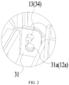
FIG. 2 is a partial enlarged view at A position inFIG. 1 . -
FIG. 3 is a schematic structure view of an anticollision strip inFIG. 1 . -
FIG. 4 is a schematic structure view of the compressor anticollision structure inFIG. 1 from another perspective. -
FIG. 5 is a partial enlarged view at B position inFIG. 4 . -
FIG. 6 is a sectional view showing connection relationships between a fixation assembly, a chassis, and a support plate inFIG. 1 . -
FIG. 7 is a schematic structure view of a nut and a gasket according to a first embodiment of the present disclosure. -
FIG. 8 is a schematic view of the structure inFIG. 7 from another perspective. -
FIG. 9 is a schematic view of the nut and the gasket according to a second embodiment of the present disclosure. -
FIG. 10 is a schematic view of the nut and the gasket according to a third embodiment of the present disclosure. -
FIG. 11 is a schematic view of the nut and the gasket according to a fourth embodiment of the present disclosure. -
FIG. 12 is a structure view of the compressor anticollision structure according to another embodiment of the present disclosure, in this view the middle partition and the anticollision strip are omitted. -
FIG. 13 is a sectional view of the compressor anticollision structure inFIG. 12 . -
FIG. 14 is an enlarged view at C position inFIG. 13 . -
FIG. 15 is a structure view of a bolt member inFIG. 14 . -
FIG. 16 is a sectional view of partial structures of the chassis inFIG. 14 , mainly showing a stepped hole, a surrounding plate, and a limiting space. -
FIG. 17 is a schematic view showing a matching relationship between the bolt member and the chassis inFIG. 14 from a perspective, in this view the bottom surface of the chassis is shown. -
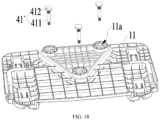
FIG. 18 is an exploded view of the structure inFIG. 17 . -
FIG. 19 is a schematic view showing a matching relationship between the bolt member and the chassis inFIG. 14 from another perspective, in this view the top surface of the chassis is shown. -
FIG. 20 is a sectional view of a fixation assembly according to another embodiment of the present disclosure. - It should be noted that, on the premise of no conflict, embodiments in the present disclosure and the technical features in the embodiments can be combined with each other. The detailed descriptions in the embodiments should be understood as explanations for the purpose of the present disclosure, and should not be regarded as improper limitations to the present disclosure. In the description of the present disclosure, the orientations or the positional relationships "top" and "bottom" are based on
FIG. 1 . The orientation or the positional relationship "lateral" is based on the orientation or positional relationship shown inFIG. 4 . The "height" refers to a direction from top to bottom inFIG. 1 . It should be understood that these orientation terms are only for the convenience of describing the present disclosure and simplifying the description, rather than indicating or implying that the device or the component must have a specific orientation, or be configured in a specific orientation and operated, and should not be understood as a limitation to the present disclosure. - An embodiment of the present disclosure provides a compressor anticollision structure for in an electrical device. As shown in
FIG. 1 andFIG. 4 , the compressor anticollision structure includes asupport assembly 10, acompressor assembly 20, and ananticollision strip 30. Thesupport assembly 10 includes achassis 11. Thecompressor assembly 20 is provided at thechassis 11 and includes acompressor 21. Theanticollision strip 30 is connected to thesupport assembly 10, and a head end of theanticollision strip 30 is connected to a tail end of theanticollision strip 30 to surround a periphery of thecompressor 21. Or, two opposite ends in a length direction of theanticollision strip 30 are respectively connected to thesupport assembly 10, and thecompressor 21 is located in an area enclosed by theanticollision strip 30 and thesupport assembly 10. - In some embodiments, a head end of the
anticollision strip 30 is connected to a tail end of theanticollision strip 30 to form an annular structure. Theanticollision strip 30 in the annular structure surrounds the periphery of thecompressor 21. When the electrical device shakes violently or falls down and causes thecompressor 21 to shake violently, theanticollision strip 30 can prevent thecompressor 21 from hitting the external components and/or other internal components of the electrical device. In other embodiments, two opposite ends in a length direction of theanticollision strip 30 are respectively connected to thesupport assembly 10, to enclose an area in which thecompressor 21 can be protected. Thecompressor 21 is located in the area, and when thecompressor 21 shakes violently, the peripheralanticollision strip 30 of thecompressor 21 or thesupport assembly 10 can prevent thecompressor 21 from hitting the external components and/or other internal components of the electrical device. - Another embodiment of the present disclosure provides an electrical device, including the compressor anticollision structure in any embodiment of the present disclosure.
- The electrical device, which has a
compressor 21, may be a dehumidifier, an air conditioner outdoor unit, or a refrigerator, and the like. - The
anticollision strip 30 is connected to thesupport assembly 10, which can prevent thecompressor 21 from hitting the external components and/or other internal components of the electrical device when thecompressor 21 shakes violently. In this case, the probability of thecompressor 21 hitting the external components and/or other internal components of the electrical device can be greatly reduced, which can improve the product quality of the electrical device. - The
anticollision strip 30 can be connected to thesupport assembly 10 in many ways. For example, as shown inFIG.1 andFIG. 4 , two opposite ends in a length direction of theanticollision strip 30 are respectively connected to thesupport assembly 10. In an embodiment, thesupport assembly 10 includes amiddle partition 12 provided at thechassis 11, and two opposite ends in a length direction of theanticollision strip 30 are respectively connected to themiddle partition 12. Themiddle partition 12 is mainly used for separating thecompressor 21 from part internal components of the electrical device. For example, themiddle partition 12 separates thecompressor 21 from the air flue, the water tank and other components. That is to say, themiddle partition 12 can prevent thecompressor 21 from hitting the internal components on the side of themiddle partition 12 away from thecompressor 21. Two opposite ends in a length direction of theanticollision strip 30 are respectively connected to themiddle partition 12. In this way, a ring of protective structure may be formed in the periphery of thecompressor 21, which may prevent thecompressor 21 from hitting the nearby external components or internal components. - It can be understood that in other embodiments, two opposite ends in a length direction of the
anticollision strip 30 may not be connected to themiddle partition 12. Thesupport assembly 10 can further include the support plate, the support pillar, and other structures provided at thechassis 11. Two opposite ends in the length direction of theanticollision strip 30 may be connected to the support plate or the support pillar. - For the connection method that a head end of the
anticollision strip 30 is connected to a tail end of theanticollision strip 30, theanticollision strip 30 may be connected to themiddle partition 12, the support plate or the support pillar. In this case, themiddle partition 12, the support plate or the support pillar are only used for fixing theanticollision strip 30, but not for enclosing an area with theanticollision strip 30 to hold thecompressor 21. - In an embodiment, as shown in
FIGS. 1 to 3 , theanticollision strip 30 includes a strip-shaped force-bearingbody 31. Theanticollision strip 30 is connected to thesupport assembly 10 through the strip-shaped force-bearingbody 31. That is, two opposite ends in a length direction of the strip-shaped force-bearingbody 31 may be connected to themiddle partition 12, the support plate or the support pillar, to enclose an area for holding thecompressor 21. - The strip-shaped force-bearing
body 31 may be components such as a sheet metal component with certain strength and rigidity. As a main force structure of theanticollision strip 30, when thecompressor 21 shakes violently and hits theanticollision strip 30, the strip-shaped force-bearingbody 31 may bear the impact from thecompressor 21. - In some embodiments, the
anticollision strip 30 further includes a firstflexible protection strip 32 provided at a side of the strip-shaped force-bearingbody 31 away from thecompressor 21. The firstflexible protection strip 32 can be made of the polyethylene (PE) sponge, the rubber foam sponge, the silicone, and the like. In some cases, when hitting the external components or other internal components of the electrical device, theanticollision strip 30 is contacted to the external components or other internal components through the firstflexible protection strip 32, which can play a cushion and protection role in preventing the external components or other internal components from damage. - In an embodiment, as shown in
FIG. 3 , theanticollision strip 30 can also include a secondflexible protection strip 33 provided at a side of the strip-shaped force-bearingbody 31 facing thecompressor 21. The secondflexible protection strip 33 can be made of the PE sponge, the rubber foam sponge, the silicone, and the like. The secondflexible protection strip 33 can prevent the strip-shaped force-bearingbody 31 from hitting thecompressor 21 to cause damage to thecompressor 21. - It can be understood that in an embodiment, a head end of the
anticollision strip 30 is connected to a tail end of theanticollision strip 30 to surround a periphery of thecompressor 21. The firstflexible protection strip 32 is provided at a side of the strip-shaped force-bearingbody 31 away from thecompressor 21, and/or, the secondflexible protection strip 33 is provided at a side of the strip-shaped force-bearingbody 31 facing thecompressor 21. - As shown in
FIG. 1 andFIG. 2 , in an embodiment, two opposite ends in a length direction of the strip-shaped force-bearingbody 31 are respectively connected to themiddle partition 12. Theanticollision strip 30 further includes at least twofirst positioning members 34, and each of the two opposite ends in the length direction of the strip-shaped force-bearingbody 31 is provided with at least one of the twofirst positioning members 34. Thesupport assembly 10 further includes at least twosecond positioning members 13 provided at themiddle partition 12. One of thefirst positioning member 34 and thesecond positioning member 13 is a positioning hole, and another of thefirst positioning member 34 and thesecond positioning member 13 is a positioning pillar. A positioning pillar is inserted in a corresponding positioning hole. - A fastener can be used for connecting each of the two opposite ends in a length direction of the strip-shaped force-bearing
body 31 with themiddle partition 12. For example, a screw can be used for fixing themiddle partition 12 on each of the two opposite ends, and the positioning pillar can be plugged in a corresponding positioning hole before installing the screws. In this way, the firstfastening connection hole 31a on the strip-shaped force-bearingbody 31 can be aligned with the secondfastening connection hole 12a on themiddle partition 12, thereby improving the assembly efficiency of theanticollision strip 30. - In an embodiment, as shown in
FIG. 4 andFIG. 5 , themiddle partition 12 includes aplate body 121 and at least oneenhanced boss 122 protruding from a side of theplate body 121 away from thecompressor 21. That is, the number of theenhanced boss 122 may be one or more. Theplate body 121 is provided at thechassis 11, and theenhanced boss 122 extends along a height direction of theplate body 121. Theenhanced boss 122 may increase structural strength and rigidity of themiddle partition 12, thereby preventing thecompressor 21 from hitting and damaging themiddle partition 12 during the shaking process of thecompressor 21. - In addition, the size of the
enhanced boss 122 in an embodiment of the present disclosure is relatively large. Therefore, a groove matching the shape of theenhanced boss 122 can be directly milled on the mold of themiddle partition 12 during production. In this way, the mold processing method is simple and convenient, and the manufacturing cost of the mold can be saved, thereby reducing the production cost of the electrical device. - In an embodiment, as shown in
FIG. 5 , along a height direction of themiddle partition 12, themiddle partition 12 includes afirst portion 121a and a second portion 121b. The second portion 121b is provided at a top side of thefirst portion 121a. A continuous steppedsurface 121c is formed in a junction between a side of thefirst portion 121a away from thecompressor 21 and a side of thesecond portion 121a away from thecompressor 21, and the continuous steppedsurface 121c extends along a lateral direction of themiddle partition 12 and departs from thechassis 11. A part of theenhanced boss 122 is provided at thefirst portion 121a of themiddle partition 12, and another part of theenhanced boss 122 is provided at the second portion 121b of themiddle partition 12. That is, eachenhanced boss 122 is divided into two sub-bosses. In order to facilitate description, the sub-boss close to thechassis 11 is the first sub-boss 1221, and the sub-boss provided at the top side of the first sub-boss 1221 is thesecond sub-boss 1222. Apart of the continuous steppedsurface 121c is located on theplate body 121, and another part of the continuous steppedsurface 121c is located at a junction between the first sub-boss 1221 and thesecond sub-boss 1222. An outer wall of the second sub-boss 1222 away from theplate body 121 can be an inclined plane, to facilitate to arrange structures such as the air flue on the side of the second sub-boss 1222 away from theplate body 121. In this way, not only the structural rigidity of themiddle partition 12 can be further improved, but also the internal structure of the electrical device can be more compact. - The number of the
enhanced bosses 122 is not limited, which can be one or more. In an embodiment, the number of theenhanced bosses 122 may be multiple, and multipleenhanced bosses 122 are distributed at intervals along a lateral direction of theplate body 121. In this case, the structural strength and rigidity of themiddle partition 12 can be further improved. - In an embodiment, as shown in
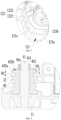
FIG. 1 andFIG. 6 , thecompressor assembly 20 further includes asupport plate 22 at a bottom of thecompressor 21, and the compressor anticollision structure includes afixation assembly 40. The number of thesupport plates 22 may be one or more. The number of thefixation assemblies 40 is the same as the number of thesupport plates 22. Thefixation assembly 40 includes asupport pillar 41 and acushion pad 42, and a bottom of thesupport pillar 41 is connected to thechassis 11. Thecushion pad 42 is sleeved outside thesupport pillar 41. Thesupport plate 22 is sleeved outside thecushion pad 42 and is spaced apart from thesupport pillar 41. A top of thecushion pad 42 has a free movement stroke along an axial direction of thecushion pad 42. When compressed 21 shakes, the top of thecushion pad 42 may move along the axial direction of thecushion pad 42. Driven by thecushion pad 42, thesupport plate 22 on thecushion pad 42 may move together with thecushion pad 42, so that thecushion pad 42 can play a cushion role for thecompressor 21. - There are many ways to make the top of the
cushion pad 42 have a free movement stroke. In an embodiment, as shown inFIG. 6 , a bottom of thecushion pad 42 is engaged with thesupport pillar 41 by an interference fit, and a top of thecushion pad 42 is engaged with thesupport pillar 41 by a loose fit. That is, the bottom of thecushion pad 42 is fastened to thesupport pillar 41. When thecompressor 21 shakes, the top of thecushion pad 42 can move along the axial direction of thecushion pad 42 on thesupport pillar 41, and the bottom of thecushion pad 42 cannot move. In some embodiments, the bottom of thecushion pad 42 may be fastened to thechassis 11, and the top of thecushion pad 42 may be engaged with thesupport pillar 41 in a loose fit, as long as the top of thecushion pad 42 has a free movement stroke along an axial direction of thecushion pad 42. - In an embodiment, as shown in
FIG. 6 , thefixation assembly 40 may further include agasket 432 and anut 431 threadedly connected to thesupport pillar 41. Thecushion pad 42 is located between thechassis 11 and thegasket 432, and anabutment surface 41a is formed at thesupport pillar 41. Thenut 431 abuts thegasket 432 on theabutment surface 41a. Along an axial direction of thesupport pillar 41, thegasket 432 is spaced apart from thecushion pad 42 and thesupport plate 22, to make the top of thecushion pad 42 have the free movement stroke along the axial direction of thecushion pad 42. - In some cases, such as the electrical device shakes violently or falls down during transportation and the
compressor 21 shakes violently, thecushion pad 42 will move along an axial direction of thecushion pad 42 in a large range. When the top of thecushion pad 42 moves to the limiting position along the axial direction close to thegasket 432, thecushion pad 42 abuts against thegasket 432. That is, thegasket 432 can limit thecushion pad 42, to limit the top of thecushion pad 42 within a certain range. - In an embodiment, as shown in
FIG. 6 , a minimum distance H1 between thecushion pad 42 and thegasket 432 is 0.5mm to 3mm along an axial direction of thesupport pillar 41. Within this distance range, thecushion pad 42 may play a better cushion and damping role, and it can be avoided that the movement range of the top of thecushion pad 42 along the axial direction becomes too large to make the shaking range of thecompressor 21 increased. - In an embodiment, as shown in
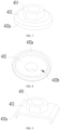
FIG. 6 to FIG. 8 , thenut 431 and thegasket 432 form an integrated structure. That is, thenut 431 and thegasket 432 are integrated together. In this way, not only the assembly efficiency can be improved, but also thenut 431 and thegasket 432 can be prevented from rubbing against each other to produce an abnormal noise when the electrical device is operating. - As shown in
FIG. 7 to FIG. 11 , thegasket 432 may be shaped in a circle, a rectangular, a polygon, or an anomalous shape, which will not be limited here. - The specific structure of the
gasket 432 is not limited. For example, thegasket 432 may be shaped in a plate, a curved plate, and the like. - In other embodiments, the
nut 431 and thegasket 432 may be separated structures fastened to each other. For example, thenut 431 and thegasket 432 can be connected together by welding. - In an embodiment, as shown in
FIG. 6 to FIG. 8 , a foldededge 432a folding towards thechassis 11 is formed at thegasket 432, and anaccommodation space 432b is enclosed by the foldededge 432a. An end of thecushion pad 42 away from thechassis 11 extends into theaccommodation space 432b, and the foldededge 432a is configured to face thesupport plate 22. When the electrical device shakes violently or falls down, the foldededge 432a can press thesupport plate 22, to avoid a too large shaking range of thecompressor 21. In this way, the possibility of thecompressor 21 hitting the external components and/or other internal components can be further reduced. - In an embodiment, as shown in
FIG. 6 , a distance H2 between a bottom surface of the foldededge 432a and a top surface of thesupport plate 22 is 0.5mm to 3mm. Within this distance range, a normal shaking range of thecompressor 21 can be ensured to play a better cushion and damping role, and thecompressor 21 can be better protected under the abnormal shaking condition. - In an embodiment, as shown in
FIG. 12 to FIG. 19 , a steppedhole 11a is formed at thechassis 11. The steppedhole 11a includes aninstallation sub-hole 11b and a non-circular sub-hole 11c at a bottom side of theinstallation sub-hole 11b. Thecompressor assembly 20 includes asupport plate 22 provided at a bottom of thecompressor 21. The compressor anticollision structure includes afixation assembly 40, and thefixation assembly 40 includes a bolt member 41', acushion pad 42, and alock member 43. The bolt member 41' includes arod body 411 and a position-limitinghead 412 connected to a bottom of therod body 411. Therod body 411 is connected to theinstallation sub-hole 11b by an interference fit, and the position-limitinghead 412 is connected to the non-circular sub-hole 11c by a stopping fit. Thecushion pad 42 is sleeved outside therod body 411. Thesupport plate 22 is sleeved outside thecushion pad 42 and is spaced apart from the bolt member 41'. Thelock member 43 is connected to therod body 411 and is provided at a top side of thecushion pad 42. - The
cushion pad 42 can play a cushion role on thecompressor 21, and thelock member 43 can limit thecushion pad 42. In this way, when the electrical device shakes violently or falls down, it can be avoided that the movement range of thecushion pad 42 along the axial direction becomes too large to make the shaking range of thecompressor 21 increased. - During the assembly process, when the
lock member 43 is screwed by the operator, the position-limitinghead 412 is connected to the non-circular sub-hole 11c by a stopping fit. In this case, the bolt member 41' can be prevented from rotating with thelock member 43, so that thelock member 43 can be screwed up. Therod body 411 is connected to theinstallation sub-hole 11b by an interference fit, which can make the bolt member 41' connected to thechassis 11 tightly. That is, in the compressor anticollision structure of the embodiments of the present disclosure, thelock member 43 can be locked on the bolt member 41', and the bolt member 41' can be connected to thechassis 11 tightly. When the electrical device shakes violently or falls down, the bolt member 41' and/or thelock member 43 are difficult to be loose. In this case, thecompressor 21 can be fastened to thechassis 11 without a large shaking range, which can greatly reduce the possibility of thecompressor 21 hitting the external components or other internal components. - In the embodiment of the present disclosure, the number of the
support plates 22 may be one or more. The number of thefixation assemblies 40 can be adjusted according to the number of thesupport plates 22, as long as eachsupport plate 22 can be connected to acorresponding fixation assembly 40 respectively. - The non-circular sub-hole 11c on the
chassis 11 can be shaped in a polygon, a semicircular, an oval, or an anomalous shape, as long as the non-circular sub-hole 11c can prevent the position-limitinghead 412 from rotating. - In an embodiment, as shown in
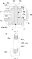
FIG. 12 to FIG. 19 , therod body 411 includes aknurling section 411a, abare section 411b, and athread section 411c. Thebare section 411b is located between theknurling section 411a and thethread section 411c. Theknurling section 411a passes through theinstallation sub-hole 11b and is connected to theinstallation sub-hole 11b by the interference fit. Thecushion pad 42 is sleeved outside thebare section 411b, and thelock member 43 is threadedly connected to thethread section 411c. - The
knurling section 411a on the bolt member 41' may help increase the contact area and friction between the bolt member 41' and a corresponding side wall of theinstallation sub-hole 11b, to make the bolt member 41' connected to thechassis 11 more tightly. Thebare section 411b may reduce the friction between the bolt member 41' and thecushion pad 42, so that thecushion pad 42 can play a cushion and damping role on thecompressor 21 by stretching out and drawing back along the axial direction. In addition, the structure of the bolt member 41' is simple, and easy to process. In this case, not only the reliability of the bolt member 41' can be improved, but also the manufacturing cost of the bolt member 41' can be saved. - The pattern on the
knurling section 411a of the bolt member 41' may be straight lines or a mesh, as long as theknurling section 411a can be connected to theinstallation sub-hole 11b by an interference fit. - In an embodiment, as shown in
FIG. 13 to FIG. 18 , the steppedhole 11a passes through thechassis 11, and the bolt member 41' passes from a bottom side of thechassis 11 into the steppedhole 11a. - In an embodiment of the present disclosure, the
chassis 11 may be an injection molding component. The bolt member 41' may be assembled on thechassis 11 in many ways. For example, when thechassis 11 is not completely cooled after injection molding, the bolt member 41' may be pressed from a bottom side of thechassis 11 into the steppedhole 11a through a tool. After thechassis 11 is completely cooled, due to thermal expansion and contraction of thechassis 11, theknurling section 411a on the bolt member 41' can be connected to theinstallation sub-hole 11b by the interference fit. For another example, after thechassis 11 is completely cooled, the bolt member 41' is heated, and the heated bolt member 41' can be pressed from the bottom side of thechassis 11 into the steppedhole 11a through the tool. After the bolt member 41' is completely cooled, theknurling section 411a on the bolt member 41' can be connected to theinstallation sub-hole 11b by the interference fit. The bolt member 41' can be assembled easily in both above two ways. - In other embodiments, the
chassis 11 can be injected on the bolt member 41'. Theknurling section 411a on the bolt member 41' and the position-limitinghead 412 can be put in the injection mold of thechassis 11 in advance. When the injection molding of thechassis 11 is finished, the bolt member 41' is integrated with thechassis 11. - In an embodiment, as shown in
FIGS. 14 to 20 , thelock member 43 is spaced apart from thecushion pad 42 along an axial direction of the bolt member 41', to make thecushion pad 42 have a free movement stroke along the axial direction of thecushion pad 42. - When the electrical device shakes violently or falls down, the
cushion pad 42 can move on thebare section 411b of the bolt member 41' along the axial direction of thecushion pad 42. Driven by thecushion pad 42, thesupport plate 22 sleeved outside thecushion pad 42 can move with thecushion pad 42 together, thereby improving the cushion and damping effect of thecushion pad 42. - In an embodiment, as shown in
FIG. 14, FIG. 15 andFIG. 20 , thelock member 43 may include anut 431 and agasket 432. Anabutment surface 41a away from thebare section 411b is formed in a junction between thethread section 411c and thebare section 411b. Thenut 431 is threadedly connected to thethread section 411c and abuts thegasket 432 on theabutment surface 41a. That is, through thegasket 432, thelock member 43 may limit thecushion pad 42, thereby limiting thecushion pad 42 within a certain movement range. - It can be understood that in some embodiments, the
lock member 43 can only have anut 431 without thegasket 432, and thenut 431 can be spaced apart from thecushion pad 42 to limit thecushion pad 42 within a certain range. - In other embodiments, the
lock member 43 may not be spaced apart from thecushion pad 42. For example, thelock member 43 can contact to thecushion pad 42, or thelock member 43 can abut against thecushion pad 42 tightly. - In an embodiment, as shown in
FIG. 14 andFIG. 20 , thecushion pad 42 includes afirst axis hole 42a and asecond axis hole 42b communicated with each other. Thefirst axis hole 42a is located at a bottom side of thesecond axis hole 42b, and a hole diameter of thefirst axis hole 42a is less than a hole diameter of thesecond axis hole 42b. Thebare section 411b passes through thefirst axis hole 42a and thesecond axis hole 42b. - The
cushion pad 42 is generally made of elastic materials, and the specifications of the bolt member 41' may be different according to different models of the electrical device. For example, the bolt member 41' with a diameter of 8mm on thebare section 411b is required in the electrical device A, and the bolt member 41' with a diameter of 10mm on thebare section 411b is required in the electrical device B, in this case, the hole diameter of thefirst axis hole 42a can be about 8mm, and thesecond axis hole 42b can be about 10mm. After the bolt member 41' with a diameter of 8mm on thebare section 411b passes through thefirst axis hole 42a and thesecond axis hole 42b, thefirst axis hole 42a can be engaged with thebare section 411b. After the bolt member 41' with a diameter of 10mm on thebare section 411b passes through thefirst axis hole 42a and thesecond axis hole 42b, thesecond axis hole 42b can be engaged with thebare section 411b. In addition, through elastic deformation, thecushion foot pad 42 enables thebare section 411b to match with thefirst axis hole 42a by the interference fit. That is, thefirst axis hole 42a and thesecond axis hole 42b with different hole diameters enable thecushion foot pad 42 to match with the bolt member 41' with different diameters on thebare section 411b. In this way, the universality of thecushion foot pad 42 can be improved. - In an embodiment, as shown in
FIG. 14 ,FIG. 16 ,FIG. 19 andFIG. 20 , the compressor anticollision structure further includes a surroundingplate 50. The surroundingplate 50 protrudes from a top surface of thechassis 11 and surrounds theinstallation sub-hole 11b to enclose a limitingspace 50a communicated with theinstallation sub-hole 11b. A bottom of thecushion pad 42 is located in the limitingspace 50a. The surroundingplate 50 can limit thecushion pad 42, to avoid a too large deviation along the radial direction of thecushion pad 42 when thecompressor 21 shakes. - The degree of the surrounding
plate 50 protruding from the top surface of thechassis 11 is not limited, as long as thecushion pad 42 can be limited and is not interfered with other components. - The surrounding
plate 50 and thechassis 11 can be integrated. For example, the surroundingplate 50 and thechassis 11 can be integrated by injection molding. The surroundingplate 50 can be connected to thechassis 11 through fasteners such as the screws, which will not be limited here. - Embodiments provided in the present disclosure can be combined with each other without contradictory.
- The above are only some embodiments of the present disclosure, and do not limit the scope of the present disclosure thereto. For those skilled in the art, various modifications and changes may be made to the present disclosure. Under the inventive concept of the present disclosure, any modifications, equivalent replacements, improvements, etc., fall within the scope of the present disclosure.
Claims (20)
- A compressor anticollision structure for an electrical device, characterized by comprising:a support assembly (10) comprising a chassis (11);a compressor assembly (20) provided at the chassis (11) and comprising a compressor (21); andan anticollision strip (30) connected to the support assembly (10),wherein:a head end of the anticollision strip (30) is connected to a tail end of the anticollision strip (30) to surround a circumference of the compressor (21), ortwo opposite ends in a length direction of the anticollision strip (30) are connected to the support assembly (10), and the compressor (21) is located in an area enclosed by the anticollision strip (30) and the support assembly (10).
- The compressor anticollision structure of claim 1, wherein the anticollision strip (30) comprises:a strip-shaped force-bearing body (31); andat least one of:a first flexible protection strip (32) provided at a side of the strip-shaped force-bearing body (31) away from the compressor (21); anda second flexible protection strip (33) provided at a side of the strip-shaped force-bearing body (31) facing the compressor (21).
- The compressor anticollision structure of claim 1 or 2, wherein:the support assembly (10) comprises a middle partition (12) provided at the chassis (11), andthe anticollision strip (30) comprises the strip-shaped force-bearing body (31), and two opposite ends in a length direction of the strip-shaped force-bearing body (31) are fastened to the middle partition (12).
- The compressor anticollision structure of claim 3, wherein:the anticollision strip (30) further comprises at least two first positioning members (34) provided at each of the two opposite ends in the length direction of the strip-shaped force-bearing body (31);the support assembly (10) further comprises at least two second positioning members (13) provided at the middle partition (12); andone of the first positioning member (34) and the second positioning member (13) is a positioning hole, another of the first positioning member (34) and the second positioning member (13) is a positioning pillar, and the positioning pillar is inserted in the positioning hole.
- The compressor anticollision structure of claim 1 or 2, wherein:the support assembly (10) comprises a middle partition (12) provided at the chassis (11), andthe middle partition (12) comprises:a plate body (121); andan enhanced boss (122) protruding from a side of the plate body (121) away from the compressor (21) and extending along a height direction of the plate body (121).
- The compressor anticollision structure of claim 5, wherein:the middle partition (12) comprises a first portion (121a) and a second portion (121b) along the height direction of the middle partition (12), the second portion (121b) is provided at a top side of the first portion (121a);a continuous stepped surface (121c) is formed at a junction between a side of the first portion (121a) away from the compressor (21) and a side of the second portion (121a) away from the compressor (21), the continuous stepped surface (121c) extending along a lateral direction of the middle partition (12) and facing away from the chassis (11); anda part of the enhanced boss (122) is provided at the first portion (121a) of the middle partition (12), and another part of the enhanced boss (122) is provided at the second portion (121b) of the middle partition (12).
- The compressor anticollision structure of claim 1 or 2, further comprising:a fixation assembly (40) comprising a support pillar (41) and a cushion pad (42), a bottom of the support pillar (41) being connected to the chassis (11), and the cushion pad (42) is sleeved outside the support pillar (41),wherein:the compressor assembly (20) further comprises a support plate (22) at a bottom of the compressor (21),the support plate (22) is sleeved outside the cushion pad (42) and is spaced apart from the support pillar (41); anda top of the cushion pad (42) has a free movement stroke along an axial direction of the cushion pad (42).
- The compressor anticollision structure of claim 7, wherein a bottom of the cushion pad (42) is engaged with the support pillar (41) by an interference fit, and a top of the cushion pad (42) is engaged with the support pillar (41) by a loose fit.
- The compressor anticollision structure of claim 7, whereinthe fixation assembly (40) further comprises:a gasket (432); anda nut (431) threadedly connected to the support pillar (41);the cushion pad (42) is located between the chassis (11) and the gasket (432);an abutment surface (41a) is formed at the support pillar (41), and the nut (431) abuts the gasket (432) on the abutment surface (41a); andthe gasket (432) is spaced apart from the cushion pad (42) and the support plate (22) along an axial direction of the support pillar (41), to allow the free movement stroke of the top of the cushion pad (42) along the axial direction of the cushion pad (42).
- The compressor anticollision structure of claim 9, wherein a minimum distance H1 between the cushion pad (42) and the gasket (432) is 0.5 mm to 3 mm along the axial direction of the support pillar (41).
- The compressor anticollision structure of claim 9, wherein:the nut (431) and the gasket (432) are separated from and fastened to each other; orthe nut (431) and the gasket (432) are integrated with each other.
- The compressor anticollision structure of claim 11, wherein:the gasket (432) comprises a folded edge (432a) folding towards the chassis (11) , and an accommodation space (432b) is enclosed by the folded edge (432a);an end of the cushion pad (42) away from the chassis (11) extends into the accommodation space (432b), and the folded edge (432a) faces the support plate (22); anda distance H2 between a bottom surface of the folded edge (432a) and a top surface of the support plate (22) is 0.5 mm to 3 mm.
- The compressor anticollision structure of claim 1 or 2, further comprising:a fixation assembly (40) comprising a bolt member (41'), a cushion pad (42), and a lock member (43);wherein:a stepped hole (11a) is formed at the chassis (11), the stepped hole (11a) comprising an installation sub-hole (11b) and a non-circular sub-hole (11c) at a bottom side of the installation sub-hole (11b);the compressor assembly (20) further comprises a support plate (22) provided at a bottom of the compressor (21);the bolt member (41') comprises:a rod body (411) connected to the installation sub-hole (11b) by an interference fit; anda position-limiting head (412) connected to a bottom of the rod body (411), the position-limiting head (412) being connected to the non-circular sub-hole (11c) by a stopping fit;the cushion pad (42) is sleeved outside the rod body (411), and the support plate (22) is sleeved outside the cushion pad (42) and is spaced apart from the bolt member (41'); andthe lock member (43) is connected to the rod body (411) and is provided at a top side of the cushion pad (42).
- The compressor anticollision structure of claim 13, wherein:the rod body (411) comprises a knurling section (411a), a bare section (411b), and a thread section (411c),
the bare section (41 1b) is located between the knurling section (411a) and the thread section (411c), andthe knurling section (411a) passes through the installation sub-hole (11b) and is connected to the installation sub-hole (11b) by an interference fit, the cushion pad (42) is sleeved outside the bare section (411b), and the lock member (43) is threadedly connected to the thread section (411c). - The compressor anticollision structure of claim 13, wherein the stepped hole (11a) passes through the chassis (11), and the bolt member (41') passes from a bottom side of the chassis (11) into the stepped hole (11a).
- The compressor anticollision structure of claim 14, wherein the lock member (43) is spaced apart from the cushion pad (42) along an axial direction of the bolt member (41'), to allow a free movement stroke of the cushion pad (42) along an axial direction of the cushion pad (42).
- The compressor anticollision structure of claim 16, wherein:the lock member (43) comprises a nut (431) and a gasket (432),an abutment surface (41a) away from the bare section (411b) is formed at a junction between the thread section (411c) and the bare section (411b), andthe nut (431) is threadedly connected to the thread section (411c) and abuts the gasket (432) on the abutment surface (41a).
- The compressor anticollision structure of claim 14, wherein:the cushion pad (42) comprises a first axis hole (42a) and a second axis hole (42b) communicating with each other,the first axis hole (42a) is located at a bottom side of the second axis hole (42b), and a hole diameter of the first axis hole (42a) is less than a hole diameter of the second axis hole (42b), andthe bare section (411b) passes through the first axis hole (42a) and the second axis hole (42b).
- The compressor anticollision structure of claim 13, further comprising:
a surrounding plate (50) protruding from a top surface of the chassis (11) and surrounding the installation sub-hole (11b) to enclose a limiting space (50a) communicating with the installation sub-hole (11b), and a bottom of the cushion pad (42) being located in the limiting space (50a). - An electrical device, characterized by comprising a compressor anticollision structure of any one of claims 1 to 19.
Applications Claiming Priority (3)
| Application Number | Priority Date | Filing Date | Title |
|---|---|---|---|
| CN202022452441.9U CN214196593U (en) | 2020-10-29 | 2020-10-29 | Compressor anti-collision structure and electrical equipment |
| CN202022534870.0U CN214405374U (en) | 2020-11-05 | 2020-11-05 | Compressor fixed knot constructs and electrical equipment |
| PCT/CN2021/126745 WO2022089489A1 (en) | 2020-10-29 | 2021-10-27 | Compressor anti-collision structure and electrical apparatus |
Publications (4)
| Publication Number | Publication Date |
|---|---|
| EP4230866A1 true EP4230866A1 (en) | 2023-08-23 |
| EP4230866A4 EP4230866A4 (en) | 2024-04-17 |
| EP4230866B1 EP4230866B1 (en) | 2025-02-26 |
| EP4230866C0 EP4230866C0 (en) | 2025-02-26 |
Family
ID=81381531
Family Applications (1)
| Application Number | Title | Priority Date | Filing Date |
|---|---|---|---|
| EP21885216.8A Active EP4230866B1 (en) | 2020-10-29 | 2021-10-27 | Compressor anti-collision structure and electrical apparatus |
Country Status (3)
| Country | Link |
|---|---|
| US (1) | US12578052B2 (en) |
| EP (1) | EP4230866B1 (en) |
| WO (1) | WO2022089489A1 (en) |
Families Citing this family (1)
| Publication number | Priority date | Publication date | Assignee | Title |
|---|---|---|---|---|
| EP4733605A1 (en) * | 2024-10-22 | 2026-04-29 | Vibracoustic SE | Fixing device for the vibration-decoupled fixing of a vehicle fastening part to a vehicle frame part |
Family Cites Families (17)
| Publication number | Priority date | Publication date | Assignee | Title |
|---|---|---|---|---|
| US4676473A (en) | 1985-06-03 | 1987-06-30 | Truckers Comfort Systems, Inc. | Compressor mounting bracket |
| KR100438613B1 (en) * | 2001-12-15 | 2004-07-02 | 엘지전자 주식회사 | Vibration damping apparatus for compressor |
| KR20040077234A (en) * | 2003-02-28 | 2004-09-04 | 엘지전자 주식회사 | shockdown rubber for compressor in refrigerator |
| CN201148721Y (en) | 2007-10-09 | 2008-11-12 | 陈天水 | Improved structure of anti-collision strip |
| CN201672634U (en) | 2010-04-12 | 2010-12-15 | Tcl集团股份有限公司 | Air-conditioner outdoor unit deflector ring anti-collision device and air-conditioner outdoor unit |
| JP6094497B2 (en) * | 2014-01-20 | 2017-03-15 | 株式会社豊田自動織機 | Electric compressor and method for manufacturing electric compressor |
| JP2017053476A (en) | 2015-09-11 | 2017-03-16 | 株式会社石黒製作所 | Strike plate for adjuster |
| CN105276073B (en) * | 2015-11-19 | 2016-06-22 | 中国人民解放军国防科学技术大学 | A kind of multidimensional multistage detection device for optics load |
| CN205783398U (en) * | 2016-07-13 | 2016-12-07 | 广东美的制冷设备有限公司 | The fixed structure of compressor and air-conditioner outdoor unit |
| CN107388419A (en) | 2017-08-24 | 2017-11-24 | 广东美的制冷设备有限公司 | Compressor and there is its air conditioner |
| CN108715120B (en) | 2017-11-20 | 2023-08-01 | 镇江康飞汽车制造股份有限公司 | Damping bracket convenient to install for refrigerator car air conditioning unit |
| CN108592242B (en) * | 2018-06-25 | 2023-07-14 | 珠海格力电器股份有限公司 | Damping structure of compressor and air conditioner |
| CN110630854B (en) * | 2019-09-12 | 2025-02-14 | 珠海格力电器股份有限公司 | A compressor vibration reduction installation structure and air conditioning equipment thereof |
| CN110645163B (en) * | 2019-10-24 | 2025-07-18 | 珠海格力电器股份有限公司 | Vibration reduction assembly for reducing vibration amplitude of compressor, compressor and air conditioner |
| CN211009011U (en) * | 2019-11-12 | 2020-07-14 | 珠海格力电器股份有限公司 | Vibration Pads, Compressors and Home Appliances |
| CN214405374U (en) | 2020-11-05 | 2021-10-15 | 广东美的制冷设备有限公司 | Compressor fixed knot constructs and electrical equipment |
| CN214196593U (en) | 2020-10-29 | 2021-09-14 | 广东美的制冷设备有限公司 | Compressor anti-collision structure and electrical equipment |
-
2021
- 2021-10-27 EP EP21885216.8A patent/EP4230866B1/en active Active
- 2021-10-27 WO PCT/CN2021/126745 patent/WO2022089489A1/en not_active Ceased
- 2021-10-27 US US18/031,553 patent/US12578052B2/en active Active
Also Published As
| Publication number | Publication date |
|---|---|
| EP4230866B1 (en) | 2025-02-26 |
| EP4230866A4 (en) | 2024-04-17 |
| WO2022089489A1 (en) | 2022-05-05 |
| US20230375126A1 (en) | 2023-11-23 |
| EP4230866C0 (en) | 2025-02-26 |
| US12578052B2 (en) | 2026-03-17 |
Similar Documents
| Publication | Publication Date | Title |
|---|---|---|
| US9133964B2 (en) | Vibration-proof clamp | |
| KR102237467B1 (en) | Fastening assembly for a fuel rail of a combustion engine | |
| EP4230866A1 (en) | Compressor anti-collision structure and electrical apparatus | |
| US20050169775A1 (en) | Apparatus for supporting compressor | |
| JP2013081043A (en) | Fixing device and antenna device | |
| US20140322979A1 (en) | Power feed socket and contact point unit used therein | |
| JP2014116132A (en) | Fixation structure and battery manufacturing method | |
| US8864116B2 (en) | Vibration insulator | |
| CN107654570B (en) | System for crankshaft damper cap | |
| CN114069198B (en) | Vehicle-mounted antenna assembly | |
| US9618071B2 (en) | Engine mount structure for apparatus equipped with engine | |
| CN214405374U (en) | Compressor fixed knot constructs and electrical equipment | |
| CN214196593U (en) | Compressor anti-collision structure and electrical equipment | |
| KR102931581B1 (en) | Power sprayer and hose guide | |
| CN221081345U (en) | Middle frame assembly and electronic equipment with same | |
| JP2009209967A (en) | Damping device | |
| JP7324635B2 (en) | Table leg structure and manufacturing method thereof | |
| CN212692916U (en) | Engine sensor protection cover and progressive die thereof | |
| CN223594705U (en) | Washers, bracket structures and electrical equipment | |
| CN222508952U (en) | Motor mounting structure and air conditioner | |
| JPS6221768Y2 (en) | ||
| CN220083292U (en) | Mounting assembly and air treatment device | |
| CN222717249U (en) | Screw guard and screw assembly | |
| CN220518102U (en) | Automobile cup stand and automobile | |
| CN107683064B (en) | Buckle structure and buckle subassembly |
Legal Events
| Date | Code | Title | Description |
|---|---|---|---|
| STAA | Information on the status of an ep patent application or granted ep patent |
Free format text: STATUS: THE INTERNATIONAL PUBLICATION HAS BEEN MADE |
|
| PUAI | Public reference made under article 153(3) epc to a published international application that has entered the european phase |
Free format text: ORIGINAL CODE: 0009012 |
|
| STAA | Information on the status of an ep patent application or granted ep patent |
Free format text: STATUS: REQUEST FOR EXAMINATION WAS MADE |
|
| 17P | Request for examination filed |
Effective date: 20230517 |
|
| AK | Designated contracting states |
Kind code of ref document: A1 Designated state(s): AL AT BE BG CH CY CZ DE DK EE ES FI FR GB GR HR HU IE IS IT LI LT LU LV MC MK MT NL NO PL PT RO RS SE SI SK SM TR |
|
| DAV | Request for validation of the european patent (deleted) | ||
| DAX | Request for extension of the european patent (deleted) | ||
| A4 | Supplementary search report drawn up and despatched |
Effective date: 20240318 |
|
| RIC1 | Information provided on ipc code assigned before grant |
Ipc: F16F 15/02 20060101ALI20240312BHEP Ipc: F04B 39/12 20060101ALI20240312BHEP Ipc: F16M 11/22 20060101ALI20240312BHEP Ipc: F04B 39/00 20060101AFI20240312BHEP |
|
| GRAP | Despatch of communication of intention to grant a patent |
Free format text: ORIGINAL CODE: EPIDOSNIGR1 |
|
| STAA | Information on the status of an ep patent application or granted ep patent |
Free format text: STATUS: GRANT OF PATENT IS INTENDED |
|
| RIC1 | Information provided on ipc code assigned before grant |
Ipc: F16F 15/02 20060101ALI20241105BHEP Ipc: F04B 39/12 20060101ALI20241105BHEP Ipc: F16M 11/22 20060101ALI20241105BHEP Ipc: F04B 39/00 20060101AFI20241105BHEP |
|
| INTG | Intention to grant announced |
Effective date: 20241121 |
|
| GRAS | Grant fee paid |
Free format text: ORIGINAL CODE: EPIDOSNIGR3 |
|
| GRAA | (expected) grant |
Free format text: ORIGINAL CODE: 0009210 |
|
| STAA | Information on the status of an ep patent application or granted ep patent |
Free format text: STATUS: THE PATENT HAS BEEN GRANTED |
|
| AK | Designated contracting states |
Kind code of ref document: B1 Designated state(s): AL AT BE BG CH CY CZ DE DK EE ES FI FR GB GR HR HU IE IS IT LI LT LU LV MC MK MT NL NO PL PT RO RS SE SI SK SM TR |
|
| REG | Reference to a national code |
Ref country code: GB Ref legal event code: FG4D |
|
| REG | Reference to a national code |
Ref country code: CH Ref legal event code: EP |
|
| REG | Reference to a national code |
Ref country code: DE Ref legal event code: R096 Ref document number: 602021026927 Country of ref document: DE |
|
| REG | Reference to a national code |
Ref country code: IE Ref legal event code: FG4D |
|
| U01 | Request for unitary effect filed |
Effective date: 20250319 |
|
| U07 | Unitary effect registered |
Designated state(s): AT BE BG DE DK EE FI FR IT LT LU LV MT NL PT RO SE SI Effective date: 20250326 |
|
| PG25 | Lapsed in a contracting state [announced via postgrant information from national office to epo] |
Ref country code: RS Free format text: LAPSE BECAUSE OF FAILURE TO SUBMIT A TRANSLATION OF THE DESCRIPTION OR TO PAY THE FEE WITHIN THE PRESCRIBED TIME-LIMIT Effective date: 20250526 |
|
| PG25 | Lapsed in a contracting state [announced via postgrant information from national office to epo] |
Ref country code: PL Free format text: LAPSE BECAUSE OF FAILURE TO SUBMIT A TRANSLATION OF THE DESCRIPTION OR TO PAY THE FEE WITHIN THE PRESCRIBED TIME-LIMIT Effective date: 20250226 |
|
| PG25 | Lapsed in a contracting state [announced via postgrant information from national office to epo] |
Ref country code: ES Free format text: LAPSE BECAUSE OF FAILURE TO SUBMIT A TRANSLATION OF THE DESCRIPTION OR TO PAY THE FEE WITHIN THE PRESCRIBED TIME-LIMIT Effective date: 20250226 |
|
| PG25 | Lapsed in a contracting state [announced via postgrant information from national office to epo] |
Ref country code: IS Free format text: LAPSE BECAUSE OF FAILURE TO SUBMIT A TRANSLATION OF THE DESCRIPTION OR TO PAY THE FEE WITHIN THE PRESCRIBED TIME-LIMIT Effective date: 20250626 Ref country code: NO Free format text: LAPSE BECAUSE OF FAILURE TO SUBMIT A TRANSLATION OF THE DESCRIPTION OR TO PAY THE FEE WITHIN THE PRESCRIBED TIME-LIMIT Effective date: 20250526 |
|
| PG25 | Lapsed in a contracting state [announced via postgrant information from national office to epo] |
Ref country code: HR Free format text: LAPSE BECAUSE OF FAILURE TO SUBMIT A TRANSLATION OF THE DESCRIPTION OR TO PAY THE FEE WITHIN THE PRESCRIBED TIME-LIMIT Effective date: 20250226 |
|
| PG25 | Lapsed in a contracting state [announced via postgrant information from national office to epo] |
Ref country code: GR Free format text: LAPSE BECAUSE OF FAILURE TO SUBMIT A TRANSLATION OF THE DESCRIPTION OR TO PAY THE FEE WITHIN THE PRESCRIBED TIME-LIMIT Effective date: 20250527 |
|
| PG25 | Lapsed in a contracting state [announced via postgrant information from national office to epo] |
Ref country code: SM Free format text: LAPSE BECAUSE OF FAILURE TO SUBMIT A TRANSLATION OF THE DESCRIPTION OR TO PAY THE FEE WITHIN THE PRESCRIBED TIME-LIMIT Effective date: 20250226 |
|
| PG25 | Lapsed in a contracting state [announced via postgrant information from national office to epo] |
Ref country code: CZ Free format text: LAPSE BECAUSE OF FAILURE TO SUBMIT A TRANSLATION OF THE DESCRIPTION OR TO PAY THE FEE WITHIN THE PRESCRIBED TIME-LIMIT Effective date: 20250226 |
|
| PG25 | Lapsed in a contracting state [announced via postgrant information from national office to epo] |
Ref country code: SK Free format text: LAPSE BECAUSE OF FAILURE TO SUBMIT A TRANSLATION OF THE DESCRIPTION OR TO PAY THE FEE WITHIN THE PRESCRIBED TIME-LIMIT Effective date: 20250226 |
|
| U20 | Renewal fee for the european patent with unitary effect paid |
Year of fee payment: 5 Effective date: 20251021 |
|
| PLBE | No opposition filed within time limit |
Free format text: ORIGINAL CODE: 0009261 |
|
| STAA | Information on the status of an ep patent application or granted ep patent |
Free format text: STATUS: NO OPPOSITION FILED WITHIN TIME LIMIT |
|
| 26N | No opposition filed |
Effective date: 20251127 |