EP4230861A1 - A method for controlling a gasoline internal combustion engine, having two spark plugs for each cylinder - Google Patents
A method for controlling a gasoline internal combustion engine, having two spark plugs for each cylinder Download PDFInfo
- Publication number
- EP4230861A1 EP4230861A1 EP23155033.6A EP23155033A EP4230861A1 EP 4230861 A1 EP4230861 A1 EP 4230861A1 EP 23155033 A EP23155033 A EP 23155033A EP 4230861 A1 EP4230861 A1 EP 4230861A1
- Authority
- EP
- European Patent Office
- Prior art keywords
- engine
- spark plug
- crank angle
- ignition
- value
- Prior art date
- Legal status (The legal status is an assumption and is not a legal conclusion. Google has not performed a legal analysis and makes no representation as to the accuracy of the status listed.)
- Granted
Links
Images





Classifications
-
- F—MECHANICAL ENGINEERING; LIGHTING; HEATING; WEAPONS; BLASTING
- F02—COMBUSTION ENGINES; HOT-GAS OR COMBUSTION-PRODUCT ENGINE PLANTS
- F02P—IGNITION, OTHER THAN COMPRESSION IGNITION, FOR INTERNAL-COMBUSTION ENGINES; TESTING OF IGNITION TIMING IN COMPRESSION-IGNITION ENGINES
- F02P5/00—Advancing or retarding ignition; Control therefor
- F02P5/04—Advancing or retarding ignition; Control therefor automatically, as a function of the working conditions of the engine or vehicle or of the atmospheric conditions
- F02P5/145—Advancing or retarding ignition; Control therefor automatically, as a function of the working conditions of the engine or vehicle or of the atmospheric conditions using electrical means
- F02P5/15—Digital data processing
- F02P5/153—Digital data processing dependent on combustion pressure
-
- F—MECHANICAL ENGINEERING; LIGHTING; HEATING; WEAPONS; BLASTING
- F02—COMBUSTION ENGINES; HOT-GAS OR COMBUSTION-PRODUCT ENGINE PLANTS
- F02P—IGNITION, OTHER THAN COMPRESSION IGNITION, FOR INTERNAL-COMBUSTION ENGINES; TESTING OF IGNITION TIMING IN COMPRESSION-IGNITION ENGINES
- F02P5/00—Advancing or retarding ignition; Control therefor
- F02P5/04—Advancing or retarding ignition; Control therefor automatically, as a function of the working conditions of the engine or vehicle or of the atmospheric conditions
- F02P5/145—Advancing or retarding ignition; Control therefor automatically, as a function of the working conditions of the engine or vehicle or of the atmospheric conditions using electrical means
-
- F—MECHANICAL ENGINEERING; LIGHTING; HEATING; WEAPONS; BLASTING
- F02—COMBUSTION ENGINES; HOT-GAS OR COMBUSTION-PRODUCT ENGINE PLANTS
- F02B—INTERNAL-COMBUSTION PISTON ENGINES; COMBUSTION ENGINES IN GENERAL
- F02B19/00—Engines characterised by precombustion chambers
- F02B19/12—Engines characterised by precombustion chambers with positive ignition
-
- F—MECHANICAL ENGINEERING; LIGHTING; HEATING; WEAPONS; BLASTING
- F02—COMBUSTION ENGINES; HOT-GAS OR COMBUSTION-PRODUCT ENGINE PLANTS
- F02P—IGNITION, OTHER THAN COMPRESSION IGNITION, FOR INTERNAL-COMBUSTION ENGINES; TESTING OF IGNITION TIMING IN COMPRESSION-IGNITION ENGINES
- F02P15/00—Electric spark ignition having characteristics not provided for in, or of interest apart from, groups F02P1/00 - F02P13/00 and combined with layout of ignition circuits
- F02P15/02—Arrangements having two or more sparking plugs
-
- F—MECHANICAL ENGINEERING; LIGHTING; HEATING; WEAPONS; BLASTING
- F02—COMBUSTION ENGINES; HOT-GAS OR COMBUSTION-PRODUCT ENGINE PLANTS
- F02P—IGNITION, OTHER THAN COMPRESSION IGNITION, FOR INTERNAL-COMBUSTION ENGINES; TESTING OF IGNITION TIMING IN COMPRESSION-IGNITION ENGINES
- F02P9/00—Electric spark ignition control, not otherwise provided for
-
- F—MECHANICAL ENGINEERING; LIGHTING; HEATING; WEAPONS; BLASTING
- F02—COMBUSTION ENGINES; HOT-GAS OR COMBUSTION-PRODUCT ENGINE PLANTS
- F02B—INTERNAL-COMBUSTION PISTON ENGINES; COMBUSTION ENGINES IN GENERAL
- F02B23/00—Other engines characterised by special shape or construction of combustion chambers to improve operation
- F02B23/08—Other engines characterised by special shape or construction of combustion chambers to improve operation with positive ignition
- F02B2023/085—Other engines characterised by special shape or construction of combustion chambers to improve operation with positive ignition using several spark plugs per cylinder
-
- Y—GENERAL TAGGING OF NEW TECHNOLOGICAL DEVELOPMENTS; GENERAL TAGGING OF CROSS-SECTIONAL TECHNOLOGIES SPANNING OVER SEVERAL SECTIONS OF THE IPC; TECHNICAL SUBJECTS COVERED BY FORMER USPC CROSS-REFERENCE ART COLLECTIONS [XRACs] AND DIGESTS
- Y02—TECHNOLOGIES OR APPLICATIONS FOR MITIGATION OR ADAPTATION AGAINST CLIMATE CHANGE
- Y02T—CLIMATE CHANGE MITIGATION TECHNOLOGIES RELATED TO TRANSPORTATION
- Y02T10/00—Road transport of goods or passengers
- Y02T10/10—Internal combustion engine [ICE] based vehicles
- Y02T10/12—Improving ICE efficiencies
Definitions
- the present invention relates to a method for controlling a gasoline internal combustion engine, wherein the engine is of the type comprising:
- the present invention relates to a method for controlling an engine of this type.
- the invention is of general application and can be used in any engine having two spark plugs per cylinder, not necessarily, therefore, in the engine illustrated in the document identified above, which constitutes only one example of application of the invention.
- the object of the present invention is to develop a new method for controlling the operation of a gasoline internal combustion engine with two spark plugs per cylinder, which is capable of obtaining maximum engine efficiency in all engine operating conditions, through a control method that is as simple as possible and - at the same time - reliable.
- the invention relates to a method for checking the operation of a gasoline internal combustion engine of the type indicated at the beginning of the present description, said method comprising the operations of:
- the optimal torque (Torque opt) that the engine can deliver is determined on the basis of the IMEPH/MFB50 curve corresponding to the engine operating point, by referring to a maximum value (IMEPh opt) assumed by IMEPh along said curve, where said maximum value corresponds to a maximum point of said curve or to a maximum point defined by an extension of said curve obtained by extrapolation.
- optimal values SA1 opt and SA2 opt of the engine crank angle of ignition of the first spark plug and the engine crank angle of ignition of the second spark plug are determined for which the value of IMEPh given by said IMEPh/MFB50 curve is a maximum value, wherein said maximum value corresponds to a maximum point defined by said curve or to a maximum point defined by an extension of said curve obtained by extrapolation
- the differentials SA1 opt - SA1 and SA2 opt - SA2 are calculated.
- a value of efficiency of the engine is determined as a function of said calculated values of the differentials SA1 opt - SA1 and SA2 opt - SA2.
- the value of the torque delivered by the engine is determined.
- said values are varied on the basis of said single normalized reference surface, moving on said surface according to a predetermined path, so as to arrive at a point on the normalized reference surface with an efficiency value corresponding to a given target value of the torque delivered by the engine.
- Said predetermined path on the xy plane of the diagram of said normalized reference surface corresponds to a sequence of lines that, for example, includes at least one straight line inclined at 45° with respect to the x, y axes, along which the variation of the differential SA1 opt - SA1 is equal to the variation of the differential SA2 opt - SA2.
- the aforesaid predetermined path is chosen on the basis of empirical data, so as to promote stability of the combustion so as to avoid a cyclic dispersion of the torque delivered by the engine.
- the invention also relates to an internal combustion engine including an electronic controller configured to implement the method described above.
- this engine is described here as an example of an engine to which the present invention is applicable.
- the method of the invention is generally applicable to any engine with two spark plugs per cylinder.
- Figure 1 is a schematic cross-sectional view of the engine, in a sectional plane showing the combustion pre-chamber with the first spark plug (which in the example is centrally located on the cylinder axis), and the main combustion chamber with the second spark plug (which in the example is lateral to the cylinder axis).
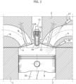
- Figure 2 is a further cross-sectional view of the engine of Figure 1 in a sectional plane showing the combustion pre-chamber with the associated spark plug, the intake duct and the exhaust duct associated with the cylinder, and respective gasoline injectors, one associated with an intake duct and the other directly associated with the main combustion chamber.
- the engine illustrated in Figures 1 , 2 comprises a crankcase 1 defining a plurality of cylinders 2 (one of which is illustrated in the drawings).
- a crankcase 1 defining a plurality of cylinders 2 (one of which is illustrated in the drawings).
- the engine configuration described below with reference to a cylinder is repeated on each of the other cylinders of the engine.
- a cylinder head 3 is mounted on the crankcase 1, in which, at each cylinder 2 the following are formed: a combustion chamber 4, at least one intake duct 5, and at least one exhaust duct 6, with which respective intake and discharge valves 7, 8 are associated (see Figure 2 ).
- a piston 9 is movable, produced according to any known configuration, connected by a piston rod 10 (shown only partially in the drawings) to a respective crank of the engine crankshaft (not shown).
- a first spark plug 11 is provided, mounted within a support element 12 defining a combustion pre-chamber 13 inside it.
- the support element 12 is configured to be mounted within a seat of the engine head 3, which leads into the combustion chamber 4.
- the support element 12 has a relatively elongated configuration, with one end carrying the spark plug 11 and the opposite end facing the combustion chamber 4 and having a plurality of orifices 14 for communication of the combustion pre-chamber 13 with the combustion chamber 4.
- the combustion pre-chamber is centrally arranged with respect to the main combustion chamber 4, and has its main axis parallel to the axis of the respective cylinder.
- different positions and orientations of the pre-chamber 13 with respect to the cylinder 2 are not excluded.
- One side of the combustion chamber 4 is provided with a second spark plug 15, with electrodes 15A directly facing the combustion chamber 4.
- the engine described here can be designed for producing a direct injection of gasoline into the combustion chamber 4, by means of an electromagnetically-controlled injector 16 directly associated with the combustion chamber 4, or to produce an indirect injection of gasoline, by means of an electromagnetically-controlled injector 17, associated with the intake duct 5, or to produce a mixed direct and indirect injection, by providing both injector devices 16, 17.
- the injector devices 16 and 17, the first spark plug 11 and the second spark plug 15 arranged for each cylinder of the engine are controlled by an electronic control unit (not illustrated).
- the engine combustion pre-chamber of the invention is of a "passive" type in that it is not associated with any device for injecting fuel or air, or a mixture of air and fuel, directly into the combustion pre-chamber 13.
- the combustion pre-chamber fills with the load of the cylinder that enters the combustion pre-chamber passing through the orifices 14, driven by the piston 9 during the compression step of the load in the cylinder.
- the electronic control unit is programmed to control the injector device 16 and/or the injector device 17 in order to produce an air/gasoline mixture in the combustion chamber according to a ratio essentially corresponding to a stoichiometric dose, or a richer dose than the stoichiometric dose.
- the electronic control unit is also programmed in such a way that the second ignition spark plug, having electrodes directly facing the combustion chamber, is only activated at low and medium engine loads to stabilize the combustion, and is inactive or kept active but without any influence on the combustion, for example, by activating it during the expansion or discharge step of the cylinder, at higher loads,
- the present invention has been developed in particular with reference to the engine described above, but is in any case applicable in general to any gasoline internal combustion engine having two spark plugs for each cylinder.
- the problem that arises in engines of this type is that of controlling the ignition of the two spark plugs of each cylinder of the engine so as to obtain maximum engine efficiency in any engine operating condition.
- Figure 3 shows a block diagram of an example of a method for controlling the ignition, which can be implemented in the electronic controller of a gasoline internal combustion engine of the conventional type, having a single spark plug for each cylinder.
- the electronic control unit of the engine is capable of commanding, for each cylinder, in each cylinder operating cycle, the ignition of the single spark plug with which the cylinder is equipped at a determined crank angle, as a function of the operating point of the engine (that is, of the values of the engine load and of the rotation speed of the engine) and as a function of a required value of the torque delivered by the engine.
- the torque (Torque) delivered by the engine is closely linked to the value of the gross mean effective pressure (IMEPh) obtained at each cycle inside the cylinder.
- Figure 3 is a flowchart showing the operations with which, in a gasoline internal combustion engine with a single spark plug per cylinder, the control unit can determine the value of the torque delivered by the engine as a function of the operating point of the engine, and as a function of the value of the engine crank angle which causes the ignition of the spark plug.
- reference maps are used, obtained empirically for a given engine, to supply an output signal 111 indicative of the optimal torque (Torque opt) which can be delivered by the engine as a function of signals 101 and 102 entering the block 100, respectively indicative of the engine load and engine rotation speed values.
- Torque opt the optimal torque
- Each pair of engine load and engine speed values represents an engine operating point.
- the block 100 makes use of different reference maps for different engine operating points.
- the block 103 makes use of reference maps, obtained empirically for a certain type of engine, to supply an output signal 105 indicative of the optimum engine crank angle for spark plug ignition ("SA opt") as a function of signals 101, 102 entering the block 103, which supply information on the engine load and engine rotation speed.
- SA opt spark plug ignition
- the block 104 receives the signal 105 containing the information relating to the value "SA opt" supplied by the block 103, and a signal 106 which supplies information on the current value of the engine crank angle "SA” which causes ignition of the spark plug.
- the block 104 outputs a signal 107 that supplies information on the difference Delta SA between the current engine crank angle of ignition of the spark plug and the optimum engine crank angle for ignition of the spark plug.
- the signal 107 containing the information on the Delta SA value is sent to a block 108, in which a single normalized curve F is used (illustrated in Figure 4 ), which supplies the engine efficiency as a function of the Delta SA value.
- the curve F is a normalized curve which is always the same whatever the operating point of the engine.
- a block 110 receives at its input both the signal 111 indicative of the optimal torque (Torque opt) which can be delivered by the engine, and the signal 109 indicative of the efficiency of the engine, and emits an output signal 112 indicative of the effective torque delivered by the engine for the operating point considered (engine load and engine speed) and for the current value of the engine crank angle at which the spark plug is ignited.
- the engine control in the case of an engine having a single spark plug per cylinder is relatively simple, thanks to the fact that it is possible to refer to a single normalized curve F ( Figure 4 ), which gives the efficiency of the engine operating the Delta SA difference between the optimum engine crank angle for spark plug ignition and the actual engine crank angle at which the spark plug ignites.
- the engine crank angle SA1 of ignition of the first spark plug and the engine crank angle SA2 of ignition of the second spark plug are determined on the basis of the operations described below.
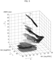
- a first operation consists in detecting empirically, for a given engine, a plurality of three-dimensional reference surfaces C1, C2, ..., Cn in a diagram with three orthogonal axes x, y, z, wherein each three-dimensional reference surface C1, C2, ..., Cn corresponds to a respective engine operating point, i.e.
- each of the aforesaid three-dimensional reference surfaces C1, C2, ..., Cn supplies on the z axis an IMEPh value (measured in bar) of the gross indicated mean effective pressure established at each cycle inside the cylinder, according to the value shown on the x axis of the engine crank angle SA1 of ignition of the first spark plug (measured in degrees BTDC, i.e. in degrees before the Top Dead Center of the piston in the cylinder) and the value reported on the y axis of the engine crank angle SA2 of ignition of the second spark plug (also measured in degrees BTDC, i.e. in degrees before Top Dead Center of the piston in the cylinder).
- a further operation envisaged in the method according to the invention consists of empirically determining, for the aforesaid engine operating points, and as a function of the engine crank angle SA1 at which the first spark plug is ignited and the engine crank angle SA2 at which the second spark plug is ignited, the value MFB50 of the engine crank angle at which 50% of the mass of fuel is burnt,
- the values of MFB50 on the x-axis are measured in degrees ATDC, i.e. in degrees after Top Dead Center, while the ordinate values of the indicated gross mean effective pressure IMEPh are expressed in bar.
- the method of the invention includes the operation of calculating, for each point of an IMEPh/MFB50 curve corresponding to a given operating point of the engine, the ratio between the value of IMEPh at that point and a maximum value (IMEPh opt) of IMEPh along said curve.
- Maximum value of the curve means the maximum value corresponding to a maximum point of the curve (as in the case of the curve Ln in Figure 6 ) or to a maximum point corresponding to an extension of the curve obtained by extrapolation (as in the case of the curves L1, L2 of Figure 6 ).
- the aforesaid ratio between the value of IMEPh at a given point of a curve in the diagram of Figure 6 and the corresponding maximum value IMEPh opt is taken as representative of the engine efficiency, since it substantially corresponds to the ratio between the torque delivered by the engine and the optimum torque that would be delivered for the aforesaid maximum value IMEPh opt of the gross indicated mean effective pressure.
- the method according to the invention therefore, includes the transformation of the aforesaid three-dimensional reference surfaces C1, C2, ... Cn illustrated in the diagram of Figure 5 in transformed three-dimensional surfaces T1, T2, ..., Tn (see Figure 7 ), which in a diagram with x, y, z axes, supply on the z axis the value of the efficiency of the engine as a function of the values SA1 of the engine crank angle of ignition of the first spark plug plotted on the x-axis, and of the values SA2 of the engine crank angle of ignition of the second spark plug plotted on the y-axis.
- the method according to the invention envisages the operation of translating each of the aforesaid transformed three-dimensional surfaces T1, T2, ..., Tn, parallel to the x axis and to the y axis (see Figure 8 ) by assigning:
- the surfaces globally indicated with G in Figure 8 are approximated with a single normalized reference surface G (see also Figure 9 ), which can be taken as a single reference, for any operating point of the engine, to determine the relationship between the torque delivered from the engine and the values SA1 and SA2 of the ignition crank angle of the first spark plug and of the ignition crank angle of the second spark plug.
- the single normalized reference surface G supplies the efficiency value of the engine (the maximum efficiency is 1) as a function of the Delta SA1 and Delta SA2 values expressed in degrees.
- the optimum torque (Torque opt) that the engine can deliver is determined, starting from given values SA1 and SA2 of the engine crank angle of ignition of the first spark plug and of the engine crank angle of ignition of the second spark plug, on the basis of the IMEPh/MFB50 curve corresponding to the engine operating point considered, referring to a maximum value (IMEPh opt) assumed by IMEPh along said curve, where this maximum value corresponds to a maximum point of the curve or a maximum point defined by an extension of the curve obtained by extrapolation.
- IMEPh opt a maximum value assumed by IMEPh along said curve
- the signal 203 leaving the block 200 and containing the information on the optimal torque (Torque opt) is sent to a block 204 for calculating the torque delivered by the engine.
- the optimal values SA1 opt and SA2 opt are determined of the engine crank angle of ignition of the first spark plug and of the engine crank angle of ignition of the second spark plug, for which the IMEPh value given by the aforesaid IMEPh/MFB50 curve is a maximum value, where maximum value means the value corresponding to a maximum point of the aforesaid curve or to a maximum point defined by an extension of the curve obtained by extrapolation.
- the signal 207 leaving from the block 205, containing the information on the optimal value SA1 opt, is sent to a block 208 which also receives a signal 209 containing the information on the current engine crank angle of ignition of the first spark plug.
- the signal 210 leaving from the block 206, containing the information on the optimal value SA2 opt, is sent to a block 211, which also receives a signal 217 containing information on the current engine crank angle of ignition of the second spark plug.
- Signals 212, 213 leave from the blocks 208, 211, indicative of the differential values SA1 opt - SA1 (Delta SA1) and SA2 opt - SA2 (Delta SA2).
- an efficiency value of the engine is determined as a function of the calculated values Delta SA1 and Delta SA2.
- the signal 215 leaving the block 214 and containing the information on the efficiency of the engine in the conditions considered, is sent to the block 204, which, on the basis of the signal 215 indicative of the efficiency of the engine and of the signal 203 indicative of the optimal torque (Torque opt), is consequently capable of outputting a signal 216 containing information on the effective torque delivered by the engine.
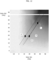
- Figure 11 illustrates the projection onto the xy plane of the normalized reference surface G.
- the zero value of Delta SA1 and the zero value of Delta SA2 correspond to the condition wherein the engine crank angle of ignition of the first spark plug and the engine crank angle of ignition of the second spark plug are the optimal values, at which the engine efficiency has value 1.
- lines such as for example the line q, the points of which correspond to the same value of the engine efficiency.
- a variation of the Delta SA1 and Delta SA2 values which corresponds to a point always situated on the line q always gives rise to the same efficiency value of the engine.
- the diagram of Figure 11 is taken as a base reference to determine how to vary the engine crank angle of ignition of the first spark plug and the engine crank angle of ignition of the second spark plug, in order to reach a point in the diagram with an efficiency value corresponding to a given target value of the torque delivered by the engine.
- the Delta SA1 and Delta SA2 values are varied by the electronic controller of the engine in order to travel the predetermined path indicated by m in Figure 11 , which starting from point A, first reaches a point B (through a variation of Delta SA1, without variation of Delta SA2) and then from point B to a target point C moving on a straight line, which in this example is inclined at 45° with respect to the x, y axes of the diagram (which corresponds to varying Delta SA1 in an identical way to varying Delta SA2).
- the predetermined path m is chosen on the basis of empirical data in such a way as to favor combustion stability and consequently reduce the cyclic dispersion of the torque delivered by the engine.
- Figures 12 , 13 illustrate two further examples of predetermined paths to be followed in the projection on the xy plane of the normalized reference surface G. Each trajectory starts from a point A, passes through a point B and arrives at a point C.
- the first section AB is covered by keeping the Delta SA2 value constant, and varying only the Delta SA1 value, after which a straight line inclined at 45° is followed, in a similar way to what has been illustrated in Figure 11 .
- point 1 is the start, in a condition wherein only the first spark plug is ignited.
- the Delta SA1 value is varied until it reaches point B, after which the curved path BC is followed by also triggering the second spark plug and varying both the Delta SA1 and Delta SA2 values.
- point C From point C to the final point D, a straight line is followed, varying both the Delta SA1 and Delta SA2 values until reaching a point with an engine efficiency corresponding to the target value of the torque delivered.
- the method according to the invention makes it possible to manage spark plug ignition control in a gasoline internal combustion engine wherein each cylinder is equipped with two spark plugs, in any case referring to a single normalized surface (surface G of Figure 9 ), usable for any operating point of the engine, which gives the advantage of simplifying the control of the engine, while still guaranteeing the reliability and robustness of the control method.
Landscapes
- Engineering & Computer Science (AREA)
- Chemical & Material Sciences (AREA)
- Combustion & Propulsion (AREA)
- Mechanical Engineering (AREA)
- General Engineering & Computer Science (AREA)
- Signal Processing (AREA)
- Ignition Installations For Internal Combustion Engines (AREA)
Abstract
Description
- The present invention relates to a method for controlling a gasoline internal combustion engine, wherein the engine is of the type comprising:
- a crankcase having a plurality of cylinders and a cylinder head defining a combustion chamber and a combustion pre-chamber associated with each cylinder, and a plurality of pistons movable within the cylinders and operatively connected to a engine shaft,
- a first spark plug and a second spark plug associated with the combustion pre-chamber and with the combustion chamber of each cylinder, respectively.
- An engine of the type indicated above has, for example, been the subject of the
European patent EP 3 453 856 B1 by the same Applicant. - The present invention relates to a method for controlling an engine of this type. Of course, the invention is of general application and can be used in any engine having two spark plugs per cylinder, not necessarily, therefore, in the engine illustrated in the document identified above, which constitutes only one example of application of the invention.
- The object of the present invention is to develop a new method for controlling the operation of a gasoline internal combustion engine with two spark plugs per cylinder, which is capable of obtaining maximum engine efficiency in all engine operating conditions, through a control method that is as simple as possible and - at the same time - reliable.
- With a view to achieving this object, the invention relates to a method for checking the operation of a gasoline internal combustion engine of the type indicated at the beginning of the present description, said method comprising the operations of:
- controlling, for each cylinder, in each cylinder operating cycle, the ignition of the first spark plug at a given engine crank angle SA1 and the ignition of the second spark plug at a given engine crank angle SA2, depending on the engine load and the engine rotational speed and depending on the required value of a torque delivered by the engine,
- determining said engine crank angle SA1 of ignition of the first spark plug and said engine crank angle SA2 of ignition of the second spark plug on the basis of the following operations:
- empirically detecting, for said engine, a plurality of three-dimensional reference surfaces, in a diagram with three orthogonal axes x, y, z, wherein each three-dimensional reference surface corresponds to a respective engine operating point, that is, to a determined pair of values of engine rotational speed and engine load, and wherein each of said three-dimensional reference surfaces provides, on the z axis, a value IMEPh of a gross indicated mean effective pressure obtained at each cycle inside the cylinder, (or other equivalent parameter indicative of the work generated in the step of the operating cycle in the cylinder which goes from the end of the intake step to the beginning of the discharge step), as a function of the value reported on the x axis of the engine crank angle SA1 of ignition of the first spark plug and the value reported on the y axis of the engine crank angle SA2 of ignition of the second spark plug,
- empirically determining, for each of the aforesaid engine operating points, and as a function of the engine crank angle SA1 at which the first spark plug is ignited and the engine crank angle SA2 at which the second spark plug is ignited, the value MFB50 of the engine crank angle at which 50% of the mass of fuel is burnt,
- on the basis of these empirical measurements, for each of the aforesaid engine operating points, defining a respective IMEPh/MFB50 curve of the variation of said gross indicated mean effective pressure IMEPh as a function of the value MFB50 of the engine crank angle at which 50% of the mass of fuel is burnt,
- calculating, for each point on said respective IMEPh/MFB50 curve, the ratio between the value of IMEPh at that point and a maximum value (IMEPh opt) of IMEPh along said curve, where said maximum value corresponds to a maximum point on said curve or to a maximum point defined by an extension of said curve obtained by extrapolation,
- taking said ratio as representative of the efficiency of the engine, corresponding substantially to the ratio between a torque delivered by the engine and an optimum torque which would be delivered for said maximum value (IMEPh opt) of IMEPh,
- on the basis of said calculation, transforming each of aforesaid three-dimensional reference surfaces, into a transformed three-dimensional surface, which, in a diagram with axes x, y, z, provides on the z axis the value of said efficiency of the engine, as a function of the values SA1 of the engine crank angle of ignition of the first spark plug reported on the x axis and of the values SA2 of the engine crank angle of ignition of the second spark plug reported on the y axis,
- translating each of said transformed three-dimensional surfaces, parallel to the x-axis and the y-axis, assigning:
- to the x-axis the values of the differential (Delta SA1) between an optimum value (SA1 opt) of the ignition crank angle of the first spark plug for which said efficiency is unitary, and the value SA1 of the ignition crank angle of the first spark plug, and
- to the y-axis the values of the differential (Delta SA2) between an optimum value (SA2 opt) of the engine crank angle of ignition of the second spark plug for which said efficiency is unitary, and the value SA2 of the ignition engine crank angle of the second spark plug,
- defining a single normalized reference surface that approximates all the aforesaid transformed and translated three-dimensional surfaces, said single normalized reference surface being used to determine, as a function of the engine operating point, the relationship between the torque delivered by the engine and the values of the engine crank angle of ignition of the first spark plug and of the engine crank angle of ignition of the second spark plug, and
- determining the values of the engine crank angle of ignition of the first spark plug and of the engine crank angle of ignition of the second spark plug using said single normalized reference surface, so as to reach a predetermined target value of the torque delivered at a given operating point of the engine.
- In the present description, and in the claims that follow, the expression "gross indicated mean effective pressure (IMEPh)" is used to indicate the indicated effective mean pressure during the operating cycle in the cylinder which goes from the end of the intake step to the beginning of the discharge step.
- In the method according to the invention, starting from determined values SA1 and/or SA2 of the engine crank angle of ignition of the first spark plug and the engine crank angle of ignition of the second spark plug, and for a determined engine operating point, the optimal torque (Torque opt) that the engine can deliver is determined on the basis of the IMEPH/MFB50 curve corresponding to the engine operating point, by referring to a maximum value (IMEPh opt) assumed by IMEPh along said curve, where said maximum value corresponds to a maximum point of said curve or to a maximum point defined by an extension of said curve obtained by extrapolation.
- According to another characteristic, for a determined engine operating point, optimal values SA1 opt and SA2 opt of the engine crank angle of ignition of the first spark plug and the engine crank angle of ignition of the second spark plug are determined for which the value of IMEPh given by said IMEPh/MFB50 curve is a maximum value, wherein said maximum value corresponds to a maximum point defined by said curve or to a maximum point defined by an extension of said curve obtained by extrapolation
- In the method according to the invention, starting from determined values SA1 and SA2 of the engine crank angle of ignition of the first spark plug and the engine crank angle of ignition of the second spark plug, and upon determining the optimal values SA1 opt and SA2 opt of said engine crank angles, the differentials SA1 opt - SA1 and SA2 opt - SA2 are calculated. On the basis of the aforesaid single normalized reference surface, a value of efficiency of the engine is determined as a function of said calculated values of the differentials SA1 opt - SA1 and SA2 opt - SA2. On the basis of said efficiency value and of said determined value of the optimal torque (Torque opt) which the engine can deliver, the value of the torque delivered by the engine is determined.
- According to another characteristic of the invention, in any engine operating condition, starting from given values of SA1 and SA2 of the engine crank angle of ignition of the first spark plug and the engine crank angle of ignition of the second spark plug, said values are varied on the basis of said single normalized reference surface, moving on said surface according to a predetermined path, so as to arrive at a point on the normalized reference surface with an efficiency value corresponding to a given target value of the torque delivered by the engine.
- Said predetermined path on the xy plane of the diagram of said normalized reference surface corresponds to a sequence of lines that, for example, includes at least one straight line inclined at 45° with respect to the x, y axes, along which the variation of the differential SA1 opt - SA1 is equal to the variation of the differential SA2 opt - SA2.
- Preferably, the aforesaid predetermined path is chosen on the basis of empirical data, so as to promote stability of the combustion so as to avoid a cyclic dispersion of the torque delivered by the engine.
- The invention also relates to an internal combustion engine including an electronic controller configured to implement the method described above.
- Further characteristics and advantages of the invention will become apparent from the description that follows with reference to the attached drawings, provided purely by way of non-limiting example, wherein:
-
Figures 1 ,2 are schematic cross-sectional views of an internal combustion engine, having two spark plugs for each cylinder, of the type that has formed the subject of theEuropean patent EP 3 453 856 B1 by the same Applicant, to which the method is applicable according to the present invention, -
Figures 3, 4 are diagrams illustrating the method for calculating the torque delivered by a conventional internal combustion engine, with a single spark plug per cylinder, as a function of the engine crank angle of ignition of the spark plug, -
Figures 5-10 are diagrams and block diagrams illustrating an example of the method according to the invention, and -
Figures 11-13 are diagrams illustrating further embodiment examples of the method according to the invention. -
Figures 1 ,2 of the attached drawings show schematic views of an embodiment example of the engine described in the Applicant'sEuropean patent EP 3 453 856 B1 . - Of course, this engine is described here as an example of an engine to which the present invention is applicable. However, as already indicated, the method of the invention is generally applicable to any engine with two spark plugs per cylinder.
-
Figure 1 is a schematic cross-sectional view of the engine, in a sectional plane showing the combustion pre-chamber with the first spark plug (which in the example is centrally located on the cylinder axis), and the main combustion chamber with the second spark plug (which in the example is lateral to the cylinder axis). -
Figure 2 is a further cross-sectional view of the engine ofFigure 1 in a sectional plane showing the combustion pre-chamber with the associated spark plug, the intake duct and the exhaust duct associated with the cylinder, and respective gasoline injectors, one associated with an intake duct and the other directly associated with the main combustion chamber. - In accordance with the conventional technique, the engine illustrated in
Figures 1 ,2 comprises acrankcase 1 defining a plurality of cylinders 2 (one of which is illustrated in the drawings). Of course, the engine configuration described below with reference to a cylinder is repeated on each of the other cylinders of the engine. Still in accordance with the conventional technique, acylinder head 3 is mounted on thecrankcase 1, in which, at eachcylinder 2 the following are formed: acombustion chamber 4, at least oneintake duct 5, and at least oneexhaust duct 6, with which respective intake anddischarge valves 7, 8 are associated (seeFigure 2 ). - Conventionally, within each
cylinder 2, apiston 9 is movable, produced according to any known configuration, connected by a piston rod 10 (shown only partially in the drawings) to a respective crank of the engine crankshaft (not shown). - Still with reference to
Figures 1 ,2 , for eachcylinder 2, afirst spark plug 11 is provided, mounted within asupport element 12 defining a combustion pre-chamber 13 inside it. Thesupport element 12 is configured to be mounted within a seat of theengine head 3, which leads into thecombustion chamber 4. Thesupport element 12 has a relatively elongated configuration, with one end carrying thespark plug 11 and the opposite end facing thecombustion chamber 4 and having a plurality oforifices 14 for communication of the combustion pre-chamber 13 with thecombustion chamber 4. - As visible in
Figures 1 ,2 , in the example shown here, the combustion pre-chamber is centrally arranged with respect to themain combustion chamber 4, and has its main axis parallel to the axis of the respective cylinder. However, different positions and orientations of the pre-chamber 13 with respect to thecylinder 2 are not excluded. - One side of the
combustion chamber 4 is provided with asecond spark plug 15, withelectrodes 15A directly facing thecombustion chamber 4. - The engine described here can be designed for producing a direct injection of gasoline into the
combustion chamber 4, by means of an electromagnetically-controlledinjector 16 directly associated with thecombustion chamber 4, or to produce an indirect injection of gasoline, by means of an electromagnetically-controlledinjector 17, associated with theintake duct 5, or to produce a mixed direct and indirect injection, by providing bothinjector devices - The
injector devices first spark plug 11 and thesecond spark plug 15 arranged for each cylinder of the engine are controlled by an electronic control unit (not illustrated). - As is apparent from the foregoing description, the engine combustion pre-chamber of the invention is of a "passive" type in that it is not associated with any device for injecting fuel or air, or a mixture of air and fuel, directly into the combustion pre-chamber 13. During operation, the combustion pre-chamber fills with the load of the cylinder that enters the combustion pre-chamber passing through the
orifices 14, driven by thepiston 9 during the compression step of the load in the cylinder. - In the case of the solution forming the subject of
EP 3 453 856 B1injector device 16 and/or theinjector device 17 in order to produce an air/gasoline mixture in the combustion chamber according to a ratio essentially corresponding to a stoichiometric dose, or a richer dose than the stoichiometric dose. The electronic control unit is also programmed in such a way that the second ignition spark plug, having electrodes directly facing the combustion chamber, is only activated at low and medium engine loads to stabilize the combustion, and is inactive or kept active but without any influence on the combustion, for example, by activating it during the expansion or discharge step of the cylinder, at higher loads, - As already indicated above, the present invention has been developed in particular with reference to the engine described above, but is in any case applicable in general to any gasoline internal combustion engine having two spark plugs for each cylinder.
- The problem that arises in engines of this type is that of controlling the ignition of the two spark plugs of each cylinder of the engine so as to obtain maximum engine efficiency in any engine operating condition.
-
Figure 3 shows a block diagram of an example of a method for controlling the ignition, which can be implemented in the electronic controller of a gasoline internal combustion engine of the conventional type, having a single spark plug for each cylinder. In an engine of this type, the electronic control unit of the engine is capable of commanding, for each cylinder, in each cylinder operating cycle, the ignition of the single spark plug with which the cylinder is equipped at a determined crank angle, as a function of the operating point of the engine (that is, of the values of the engine load and of the rotation speed of the engine) and as a function of a required value of the torque delivered by the engine. - The torque (Torque) delivered by the engine is closely linked to the value of the gross mean effective pressure (IMEPh) obtained at each cycle inside the cylinder. The efficiency (η) of the engine, understood as the ratio between the torque ("Torque") delivered by the engine and the optimal torque ("Torque opt") delivered by the engine is equal to the ratio between the IMEPh in the cylinder and the maximum value IMEPh opt which can be obtained in the cylinder:

- If SA is the engine crank angle at which the ignition of the single spark plug of each cylinder is commanded and SAopt is the engine crank angle of ignition of the spark plug that gives rise to the optimal value IMEPh opt in the cylinder, it follows that the efficiency of the engine is a function of the difference between the optimum ignition angle and the effective ignition angle:

-
Figure 3 is a flowchart showing the operations with which, in a gasoline internal combustion engine with a single spark plug per cylinder, the control unit can determine the value of the torque delivered by the engine as a function of the operating point of the engine, and as a function of the value of the engine crank angle which causes the ignition of the spark plug. - In
Figure 3 , inblock 100 reference maps are used, obtained empirically for a given engine, to supply anoutput signal 111 indicative of the optimal torque (Torque opt) which can be delivered by the engine as a function ofsignals block 100, respectively indicative of the engine load and engine rotation speed values. Each pair of engine load and engine speed values represents an engine operating point. Theblock 100 makes use of different reference maps for different engine operating points. - Again in
Figure 3 , theblock 103 makes use of reference maps, obtained empirically for a certain type of engine, to supply anoutput signal 105 indicative of the optimum engine crank angle for spark plug ignition ("SA opt") as a function ofsignals block 103, which supply information on the engine load and engine rotation speed. - The
block 104 receives thesignal 105 containing the information relating to the value "SA opt" supplied by theblock 103, and asignal 106 which supplies information on the current value of the engine crank angle "SA" which causes ignition of the spark plug. Theblock 104 outputs asignal 107 that supplies information on the difference Delta SA between the current engine crank angle of ignition of the spark plug and the optimum engine crank angle for ignition of the spark plug. - The
signal 107 containing the information on the Delta SA value is sent to ablock 108, in which a single normalized curve F is used (illustrated inFigure 4 ), which supplies the engine efficiency as a function of the Delta SA value. The curve F is a normalized curve which is always the same whatever the operating point of the engine. - A
block 110 receives at its input both thesignal 111 indicative of the optimal torque (Torque opt) which can be delivered by the engine, and thesignal 109 indicative of the efficiency of the engine, and emits anoutput signal 112 indicative of the effective torque delivered by the engine for the operating point considered (engine load and engine speed) and for the current value of the engine crank angle at which the spark plug is ignited. - Therefore, the engine control in the case of an engine having a single spark plug per cylinder is relatively simple, thanks to the fact that it is possible to refer to a single normalized curve F (
Figure 4 ), which gives the efficiency of the engine operating the Delta SA difference between the optimum engine crank angle for spark plug ignition and the actual engine crank angle at which the spark plug ignites. - In the case of a gasoline internal combustion engine having two spark plugs per cylinder, which can be controlled independently, the problem arises of identifying a simple and reliable way to control the engine crank angle of ignition of the first spark plug associated with the combustion pre-chamber (
spark plug 11 inFigure 1 ) and the engine crank angle of ignition of the second spark plug whose electrodes directly face the combustion chamber (spark plug 15 inFigure 1 ) in order to obtain a required torque from the engine in any engine operating condition. - In the method according to the invention the engine crank angle SA1 of ignition of the first spark plug and the engine crank angle SA2 of ignition of the second spark plug are determined on the basis of the operations described below.
- With reference to
Figure 5 of the attached drawings, a first operation consists in detecting empirically, for a given engine, a plurality of three-dimensional reference surfaces C1, C2, ..., Cn in a diagram with three orthogonal axes x, y, z, wherein each three-dimensional reference surface C1, C2, ..., Cn corresponds to a respective engine operating point, i.e. to a determined pair of values of the engine rotation speed and engine load, and wherein each of the aforesaid three-dimensional reference surfaces C1, C2, ..., Cn supplies on the z axis an IMEPh value (measured in bar) of the gross indicated mean effective pressure established at each cycle inside the cylinder, according to the value shown on the x axis of the engine crank angle SA1 of ignition of the first spark plug (measured in degrees BTDC, i.e. in degrees before the Top Dead Center of the piston in the cylinder) and the value reported on the y axis of the engine crank angle SA2 of ignition of the second spark plug (also measured in degrees BTDC, i.e. in degrees before Top Dead Center of the piston in the cylinder). - As an alternative to the above, instead of the aforesaid IMEPh parameter, it is possible to refer to another equivalent parameter, such as, for example, the work generated in the step of the operating cycle in the cylinder which goes from the end of the intake step to the beginning of the discharge step.
- With reference to
Figure 6 , a further operation envisaged in the method according to the invention consists of empirically determining, for the aforesaid engine operating points, and as a function of the engine crank angle SA1 at which the first spark plug is ignited and the engine crank angle SA2 at which the second spark plug is ignited, the value MFB50 of the engine crank angle at which 50% of the mass of fuel is burnt, - On the basis of the aforesaid empirical findings, for each of the aforesaid engine operating points, corresponding to a pair of values of the engine rotation speed and engine load, it is possible to define a respective curve IMEPh/MFB50 (in
Figure 6 these curves are indicated by L1, L2, ..., Ln) which supplies the value IMEPh of the gross indicated mean effective pressure as a function of the value MFB50 of the engine crank angle at which 50% of the fuel mass is burnt. - With reference to
Figure 6 , the values of MFB50 on the x-axis are measured in degrees ATDC, i.e. in degrees after Top Dead Center, while the ordinate values of the indicated gross mean effective pressure IMEPh are expressed in bar. - On the basis of the diagram of
Figure 6 , which is obtained empirically for a given engine, the method of the invention includes the operation of calculating, for each point of an IMEPh/MFB50 curve corresponding to a given operating point of the engine, the ratio between the value of IMEPh at that point and a maximum value (IMEPh opt) of IMEPh along said curve. Maximum value of the curve means the maximum value corresponding to a maximum point of the curve (as in the case of the curve Ln inFigure 6 ) or to a maximum point corresponding to an extension of the curve obtained by extrapolation (as in the case of the curves L1, L2 ofFigure 6 ). - In the method according to the invention, the aforesaid ratio between the value of IMEPh at a given point of a curve in the diagram of
Figure 6 and the corresponding maximum value IMEPh opt is taken as representative of the engine efficiency, since it substantially corresponds to the ratio between the torque delivered by the engine and the optimum torque that would be delivered for the aforesaid maximum value IMEPh opt of the gross indicated mean effective pressure. - On the basis of the aforesaid calculation, the method according to the invention, therefore, includes the transformation of the aforesaid three-dimensional reference surfaces C1, C2, ... Cn illustrated in the diagram of
Figure 5 in transformed three-dimensional surfaces T1, T2, ..., Tn (seeFigure 7 ), which in a diagram with x, y, z axes, supply on the z axis the value of the efficiency of the engine as a function of the values SA1 of the engine crank angle of ignition of the first spark plug plotted on the x-axis, and of the values SA2 of the engine crank angle of ignition of the second spark plug plotted on the y-axis. - At this point, the method according to the invention envisages the operation of translating each of the aforesaid transformed three-dimensional surfaces T1, T2, ..., Tn, parallel to the x axis and to the y axis (see
Figure 8 ) by assigning: - to the x-axis the values of the differential (Delta SA1) between an optimum value (SA1 opt) of the ignition crank angle of the first spark plug for which the efficiency is unitary and the value SA2 of the ignition crank angle of the first spark plug, and
- to the y-axis the values of the differential (Delta SA2) between an optimum value (SA2 opt) of the engine crank angle of ignition of the second spark plug for which said efficiency is unitary and the value SA2 of the engine crank angle of ignition of the second spark plug, in such a way as to obtain transformed and translated three-dimensional surfaces globally indicated with the reference G in
Figure 8 . - The surfaces globally indicated with G in
Figure 8 are approximated with a single normalized reference surface G (see alsoFigure 9 ), which can be taken as a single reference, for any operating point of the engine, to determine the relationship between the torque delivered from the engine and the values SA1 and SA2 of the ignition crank angle of the first spark plug and of the ignition crank angle of the second spark plug. InFigure 9 , the single normalized reference surface G supplies the efficiency value of the engine (the maximum efficiency is 1) as a function of the Delta SA1 and Delta SA2 values expressed in degrees. - With reference to
Figure 10 , in theblock 200, for a determined engine operating point, i.e. as a function ofsignals - The
signal 203 leaving theblock 200 and containing the information on the optimal torque (Torque opt) is sent to ablock 204 for calculating the torque delivered by the engine. - Again with reference to
Figure 10 , in theblocks signals - The
signal 207 leaving from theblock 205, containing the information on the optimal value SA1 opt, is sent to ablock 208 which also receives asignal 209 containing the information on the current engine crank angle of ignition of the first spark plug. - The
signal 210 leaving from theblock 206, containing the information on the optimal value SA2 opt, is sent to ablock 211, which also receives asignal 217 containing information on the current engine crank angle of ignition of the second spark plug.Signals blocks - Again with reference to
Figure 10 , in theblock 214, on the basis of the aforesaid single normalized surface G (Figure 9 ), an efficiency value of the engine is determined as a function of the calculated values Delta SA1 and Delta SA2. Thesignal 215 leaving theblock 214 and containing the information on the efficiency of the engine in the conditions considered, is sent to theblock 204, which, on the basis of thesignal 215 indicative of the efficiency of the engine and of thesignal 203 indicative of the optimal torque (Torque opt), is consequently capable of outputting asignal 216 containing information on the effective torque delivered by the engine. -
Figure 11 illustrates the projection onto the xy plane of the normalized reference surface G. In the xy plane illustrated inFigure 11 , the zero value of Delta SA1 and the zero value of Delta SA2 correspond to the condition wherein the engine crank angle of ignition of the first spark plug and the engine crank angle of ignition of the second spark plug are the optimal values, at which the engine efficiency hasvalue 1. In the diagram ofFigure 11 , it is therefore possible to identify lines, such as for example the line q, the points of which correspond to the same value of the engine efficiency. In other words, a variation of the Delta SA1 and Delta SA2 values, which corresponds to a point always situated on the line q always gives rise to the same efficiency value of the engine. - During engine operation, the diagram of
Figure 11 is taken as a base reference to determine how to vary the engine crank angle of ignition of the first spark plug and the engine crank angle of ignition of the second spark plug, in order to reach a point in the diagram with an efficiency value corresponding to a given target value of the torque delivered by the engine. Assuming, for example, that the starting condition of the engine corresponds to the point indicated with A inFigure 11 , the Delta SA1 and Delta SA2 values are varied by the electronic controller of the engine in order to travel the predetermined path indicated by m inFigure 11 , which starting from point A, first reaches a point B (through a variation of Delta SA1, without variation of Delta SA2) and then from point B to a target point C moving on a straight line, which in this example is inclined at 45° with respect to the x, y axes of the diagram (which corresponds to varying Delta SA1 in an identical way to varying Delta SA2). - The predetermined path m is chosen on the basis of empirical data in such a way as to favor combustion stability and consequently reduce the cyclic dispersion of the torque delivered by the engine.
-
Figures 12 ,13 illustrate two further examples of predetermined paths to be followed in the projection on the xy plane of the normalized reference surface G. Each trajectory starts from a point A, passes through a point B and arrives at a point C. In the case ofFigure 12 , the first section AB is covered by keeping the Delta SA2 value constant, and varying only the Delta SA1 value, after which a straight line inclined at 45° is followed, in a similar way to what has been illustrated inFigure 11 . - In the case of
Figure 13 ,point 1 is the start, in a condition wherein only the first spark plug is ignited. In this condition, the Delta SA1 value is varied until it reaches point B, after which the curved path BC is followed by also triggering the second spark plug and varying both the Delta SA1 and Delta SA2 values. From point C to the final point D, a straight line is followed, varying both the Delta SA1 and Delta SA2 values until reaching a point with an engine efficiency corresponding to the target value of the torque delivered. - As is evident from the preceding description, the method according to the invention makes it possible to manage spark plug ignition control in a gasoline internal combustion engine wherein each cylinder is equipped with two spark plugs, in any case referring to a single normalized surface (surface G of
Figure 9 ), usable for any operating point of the engine, which gives the advantage of simplifying the control of the engine, while still guaranteeing the reliability and robustness of the control method. - Of course, without prejudice to the principle of the invention, the details of construction of the engine and the embodiments of the method may vary widely with respect to those described and illustrated purely by way of example, without departing from the scope of the present invention, as defined by the attached claims.
Claims (9)
- A method for controlling the operation of a gasoline internal combustion engine,wherein said engine comprises:- a crankcase (1) having a plurality of cylinders (2) and a cylinder head (3) defining a combustion chamber (4) and a combustion pre-chamber (13) associated with each cylinder (2), and a plurality of pistons (9) movable within the cylinders (2) and operatively connected to an engine shaft,- a first spark plug (11) and a second spark plug (15) associated with the combustion pre-chamber (13) and the combustion chamber (4) of each cylinder (2), respectively,wherein said method comprises the operations of- controlling, for each cylinder (2), in each cylinder operating cycle, the ignition of the first spark plug (11) at a given engine crank angle (SA1) and the ignition of the second spark plug (15) at a given engine crank angle (SA2), depending on the engine load and the engine rotational speed and depending on a required value of a torque delivered by the engine,- determining said engine crank angle (SA1) of ignition of the first spark plug and said engine crank angle (SA2) of ignition of the second spark plug on the basis of the following operations:- empirically detecting, for said engine, a plurality of three-dimensional reference surfaces (C1, C2,.... Cn), in a diagram with three orthogonal axes x, y, z, wherein each three-dimensional reference surface corresponds to a respective engine operating point, that is, to a determined pair of values of engine rotational speed and engine load, and wherein each of said three-dimensional reference surfaces provides, on the z axis, a value of a gross indicated mean effective pressure (IMEPh) obtained at each cycle inside the cylinder (2), as a function of the value reported on the x axis of the engine crank angle (SA1) of ignition of the first spark plug, and the value reported on the y axis of the engine crank angle (SA2) of ignition of the second spark plug,- empirically determining, for each of the aforesaid engine operating points, and as a function of the engine crank angle (SA1) at which the first spark plug is ignited and the engine crank angle (SA2) at which the second spark plug is ignited, the value (MFB50) of the engine crank angle at which 50% of the mass of fuel is burnt,- on the basis of these empirical measurements, for each of the aforesaid engine operating points, defining a respective IMEPh/MFB50 curve of the variation of said gross indicated mean effective pressure (IMEPh) as a function of the value (MFB50) of the engine crank angle at which 50% of the fuel mass is burnt,- calculating, for each point on said IMEPh/MFB50 curve, the ratio between the value of IMEPh at that point and a maximum value (IMEPh opt) of IMEPh along said curve, where said maximum value corresponds to a maximum point on said curve or to a maximum point defined by an extension of said curve obtained by extrapolation,- taking said ratio as representative of the efficiency of the engine, corresponding substantially to the ratio between a torque delivered by the engine and an optimum torque, which would be delivered for said maximum value (IMEPh opt) of IMEPh,- on the basis of said calculation, transforming each of aforesaid three-dimensional reference surfaces (C1, C2, ...Cn), into a transformed three-dimensional surface (T1, T2, ...Tn), which, in a diagram with axes x, y, z, provides on the z axis the value of said efficiency (η) of the engine, as a function of the value (SA1) of the engine crank angle of ignition of the first spark plug on the x axis and of the value (SA2) of the engine crank angle of ignition of the second spark plug on the y axis,- translating each of said transformed three-dimensional surfaces, parallel to the x-axis and the y-axis, assigning:to the x-axis the values of the differential (Delta SA1) between an optimum value (SA1 opt) of the ignition crank angle of the first spark plug for which said efficiency (η) is unitary, and the value (SA1) of the ignition crank angle of the first spark plug, andto the y axis the values of the differential (Delta SA2) between an optimum value (SA2 opt) of the engine crank angle of ignition of the second spark plug for which said efficiency (η) is unitary, and the value (SA2) of the engine crank angle of ignition of the second spark plug,- defining a single normalized reference surface (G) which approximates all the aforesaid transformed and translated three-dimensional surfaces, said single normalized reference surface (G) being used to determine, as a function of the engine operating point, the relationship between the torque delivered by the engine (Torque) and the values (SA1 and SA2) of the engine crank angle of ignition of the first spark plug and of the engine crank angle of ignition of the second spark plug, and- determining the values (SA1 and SA2) of the engine crank angle of ignition of the first spark plug and of the engine crank angle of ignition of the second spark plug using said single normalized reference surface (G), so as to reach a target value of the torque delivered at a given operating point of the engine.
- A method according to claim 1, characterized in that starting from determined values (SA1 and SA2) of the engine crank angle of ignition of the first spark plug and/or the engine crank angle of ignition of the second spark plug, and for a determined engine operating point, the optimal torque (Torque opt) which the engine can deliver is determined on the basis of the IMEPH/MFB50 curve corresponding to the engine operating point, by referring to a maximum value (IMEPh opt) assumed by IMEPh along said curve, where said maximum value corresponds to a maximum point of said curve or to a maximum point defined by an extension of said curve obtained by extrapolation.
- A method according to claim 2, characterized in that for a determined engine operating point, optimal values (SA1 opt and SA2 opt) of the engine crank angle of ignition of the first spark plug and the engine crank angle of ignition of the second spark plug are determined, for which the value of IMEPh given by said IMEPh/MFB50 curve is a maximum value, wherein said maximum value corresponds to a maximum point defined by said curve or to a maximum point defined by an extension of said curve obtained by extrapolation.
- A method according to claim 3, characterized in that starting from determined values (SA1 and SA2) of the engine crank angle of ignition of the first spark plug and the engine crank angle of ignition of the second spark plug, and upon determining the optimal values (SA1 opt) and (SA2 opt) of said engine crank angles, the differentials SA1 opt - SA1 and SA2 opt - SA2 are calculated.
- A method according to claim 4, characterized in that, on the basis of said single normalized reference surface (G), a value of efficiency (η) of the engine is determined as a function of said calculated values of the differentials SA1 opt - SA1 and SA2 opt - SA2,
and in that on the basis of said efficiency value (η) and of said determined value of the optimal torque (Torque opt) which the engine can deliver, the value of the torque (Torque) delivered by the engine is determined. - A method according to claim 1, characterized in that in any engine operating condition, starting from given values (SA1 and SA2) of the engine crank angle of ignition of the first spark plug and the engine crank angle of ignition of the second spark plug, said values are varied on the basis of said single normalized reference surface (G), moving on said surface according to a predetermined path (m), so as to arrive at a point on the normalized reference surface (G) with an efficiency value (η) corresponding to a given target value of the torque (Torque) delivered by the engine.
- A method according to claim 6, characterized in that said predetermined path (m) corresponds to a sequence of lines in the xy plane of the diagram of said normalized reference surface (G), including at least one straight line inclined at 45° with respect to the x, y axes, along which the variation of the differential SA1 opt - SA1 is equal to the variation of the differential SA2 opt - SA2.
- A method according to claim 6, characterized in that said predetermined path (m) is chosen on the basis of empirical data, so as to favor a stable combustion, reducing the cyclic dispersion of the torque delivered by the engine.
- A gasoline internal combustion engine, comprising:- a crankcase (1) having a plurality of cylinders (2) and a cylinder head (3) defining a combustion chamber (4) and a combustion pre-chamber (13) associated with each cylinder (2), and a plurality of pistons (9) movable within the cylinders (2) and operatively connected to an engine shaft,- a first spark plug (11) and a second spark plug (15) associated with the combustion pre-chamber (13) and with the combustion chamber (4) of each cylinder (2), respectively, and- an electronic controller configured to implement a method according to any one of the preceding claims.
Applications Claiming Priority (1)
| Application Number | Priority Date | Filing Date | Title |
|---|---|---|---|
| IT102022000003029A IT202200003029A1 (en) | 2022-02-18 | 2022-02-18 | "Procedure for controlling a petrol internal combustion engine, having two spark plugs for each cylinder" |
Publications (3)
| Publication Number | Publication Date |
|---|---|
| EP4230861A1 true EP4230861A1 (en) | 2023-08-23 |
| EP4230861C0 EP4230861C0 (en) | 2024-07-24 |
| EP4230861B1 EP4230861B1 (en) | 2024-07-24 |
Family
ID=81648198
Family Applications (1)
| Application Number | Title | Priority Date | Filing Date |
|---|---|---|---|
| EP23155033.6A Active EP4230861B1 (en) | 2022-02-18 | 2023-02-06 | A method for controlling a gasoline internal combustion engine, having two spark plugs for each cylinder |
Country Status (4)
| Country | Link |
|---|---|
| US (1) | US11859591B2 (en) |
| EP (1) | EP4230861B1 (en) |
| CN (1) | CN116624307A (en) |
| IT (1) | IT202200003029A1 (en) |
Families Citing this family (1)
| Publication number | Priority date | Publication date | Assignee | Title |
|---|---|---|---|---|
| DE102024206726A1 (en) * | 2024-07-17 | 2026-01-22 | Robert Bosch Gesellschaft mit beschränkter Haftung | Methods for determining an ignition angle efficiency and methods for determining a combination of ignition angles |
Citations (3)
| Publication number | Priority date | Publication date | Assignee | Title |
|---|---|---|---|---|
| WO1994013946A1 (en) * | 1992-12-14 | 1994-06-23 | Transcom Gas Technologies Pty. Ltd. | Engine control unit |
| US20070221164A1 (en) * | 2006-03-24 | 2007-09-27 | Nissan Motor Co., Ltd. | Auxiliary combustion chamber type internal combustion engine |
| EP3453856B1 (en) | 2017-09-08 | 2019-10-16 | MASERATI S.p.A. | Gasoline internal combustion engine, with a combustion pre-chamber and two spark plugs |
-
2022
- 2022-02-18 IT IT102022000003029A patent/IT202200003029A1/en unknown
-
2023
- 2023-02-06 EP EP23155033.6A patent/EP4230861B1/en active Active
- 2023-02-16 US US18/170,005 patent/US11859591B2/en active Active
- 2023-02-20 CN CN202310137414.8A patent/CN116624307A/en active Pending
Patent Citations (3)
| Publication number | Priority date | Publication date | Assignee | Title |
|---|---|---|---|---|
| WO1994013946A1 (en) * | 1992-12-14 | 1994-06-23 | Transcom Gas Technologies Pty. Ltd. | Engine control unit |
| US20070221164A1 (en) * | 2006-03-24 | 2007-09-27 | Nissan Motor Co., Ltd. | Auxiliary combustion chamber type internal combustion engine |
| EP3453856B1 (en) | 2017-09-08 | 2019-10-16 | MASERATI S.p.A. | Gasoline internal combustion engine, with a combustion pre-chamber and two spark plugs |
Also Published As
| Publication number | Publication date |
|---|---|
| EP4230861C0 (en) | 2024-07-24 |
| US11859591B2 (en) | 2024-01-02 |
| IT202200003029A1 (en) | 2023-08-18 |
| EP4230861B1 (en) | 2024-07-24 |
| US20230265820A1 (en) | 2023-08-24 |
| CN116624307A (en) | 2023-08-22 |
Similar Documents
| Publication | Publication Date | Title |
|---|---|---|
| JP4482260B2 (en) | Method and apparatus for determining difference in control amount for each individual cylinder in a multi-cylinder internal combustion engine | |
| US5713328A (en) | Spark ignited internal combustion engine with multiple event fuel injection | |
| US6550444B2 (en) | Premixed-compression-ignition internal combustion engine and method of controlling the same | |
| US8050848B2 (en) | Method and system for igniting a lean fuel mixture in a main chamber of an internal combustion engine | |
| US5038737A (en) | Control apparatus for an internal combustion engine | |
| EP0491381A2 (en) | A fuel injection control device for an internal combustion engine | |
| JPS58222944A (en) | Control of composition of supplied air and external ignition type internal combustion engine | |
| EP4230861B1 (en) | A method for controlling a gasoline internal combustion engine, having two spark plugs for each cylinder | |
| US4727842A (en) | Engine ignition timing control apparatus | |
| US6209520B1 (en) | Method and apparatus for cylinder balancing | |
| EP1262648B1 (en) | Control apparatus of internal combustion engine | |
| FI121030B (en) | Pilot fuel control system and method for internal combustion engine | |
| CN116733651B (en) | internal combustion engine | |
| EP1164276B1 (en) | Internal combustion engine with external assist for stable auto-ignition | |
| US5067459A (en) | Fuel timing control | |
| JPS5825547A (en) | How to control the combustion process of an internal combustion engine | |
| KR102160518B1 (en) | Method for compensating a gas spring action in the case of cylinder shutoff with exhaust gas inclusion | |
| US20250244207A1 (en) | System and method for misfire detection for dual spark plug engine | |
| US4970667A (en) | Apparatus for detecting a crankshaft position at which maximum cylinder pressure appears | |
| CN118974387A (en) | Internal combustion engine | |
| US20230203998A1 (en) | Internal combustion engine | |
| JPH01208571A (en) | Device for detecting igniting condition of engine and method for controlling ignition plug | |
| CN115977846A (en) | internal combustion engine | |
| JP2021124071A (en) | Control device of internal combustion engine | |
| JP2003314342A (en) | Method and apparatus for adjusting fuel injection timing of internal combustion engine |
Legal Events
| Date | Code | Title | Description |
|---|---|---|---|
| PUAI | Public reference made under article 153(3) epc to a published international application that has entered the european phase |
Free format text: ORIGINAL CODE: 0009012 |
|
| STAA | Information on the status of an ep patent application or granted ep patent |
Free format text: STATUS: THE APPLICATION HAS BEEN PUBLISHED |
|
| AK | Designated contracting states |
Kind code of ref document: A1 Designated state(s): AL AT BE BG CH CY CZ DE DK EE ES FI FR GB GR HR HU IE IS IT LI LT LU LV MC ME MK MT NL NO PL PT RO RS SE SI SK SM TR |
|
| STAA | Information on the status of an ep patent application or granted ep patent |
Free format text: STATUS: REQUEST FOR EXAMINATION WAS MADE |
|
| 17P | Request for examination filed |
Effective date: 20231011 |
|
| RBV | Designated contracting states (corrected) |
Designated state(s): AL AT BE BG CH CY CZ DE DK EE ES FI FR GB GR HR HU IE IS IT LI LT LU LV MC ME MK MT NL NO PL PT RO RS SE SI SK SM TR |
|
| GRAP | Despatch of communication of intention to grant a patent |
Free format text: ORIGINAL CODE: EPIDOSNIGR1 |
|
| STAA | Information on the status of an ep patent application or granted ep patent |
Free format text: STATUS: GRANT OF PATENT IS INTENDED |
|
| RIC1 | Information provided on ipc code assigned before grant |
Ipc: F02B 23/08 20060101ALN20240220BHEP Ipc: F02B 19/12 20060101ALI20240220BHEP Ipc: F02B 19/10 20060101ALI20240220BHEP Ipc: F02P 15/02 20060101AFI20240220BHEP |
|
| INTG | Intention to grant announced |
Effective date: 20240312 |
|
| GRAS | Grant fee paid |
Free format text: ORIGINAL CODE: EPIDOSNIGR3 |
|
| GRAA | (expected) grant |
Free format text: ORIGINAL CODE: 0009210 |
|
| STAA | Information on the status of an ep patent application or granted ep patent |
Free format text: STATUS: THE PATENT HAS BEEN GRANTED |
|
| AK | Designated contracting states |
Kind code of ref document: B1 Designated state(s): AL AT BE BG CH CY CZ DE DK EE ES FI FR GB GR HR HU IE IS IT LI LT LU LV MC ME MK MT NL NO PL PT RO RS SE SI SK SM TR |
|
| REG | Reference to a national code |
Ref country code: GB Ref legal event code: FG4D |
|
| REG | Reference to a national code |
Ref country code: CH Ref legal event code: EP |
|
| REG | Reference to a national code |
Ref country code: IE Ref legal event code: FG4D Ref country code: DE Ref legal event code: R096 Ref document number: 602023000267 Country of ref document: DE |
|
| U01 | Request for unitary effect filed |
Effective date: 20240801 |
|
| U07 | Unitary effect registered |
Designated state(s): AT BE BG DE DK EE FI FR IT LT LU LV MT NL PT SE SI Effective date: 20240816 |
|
| PG25 | Lapsed in a contracting state [announced via postgrant information from national office to epo] |
Ref country code: NO Free format text: LAPSE BECAUSE OF FAILURE TO SUBMIT A TRANSLATION OF THE DESCRIPTION OR TO PAY THE FEE WITHIN THE PRESCRIBED TIME-LIMIT Effective date: 20241024 |
|
| PG25 | Lapsed in a contracting state [announced via postgrant information from national office to epo] |
Ref country code: GR Free format text: LAPSE BECAUSE OF FAILURE TO SUBMIT A TRANSLATION OF THE DESCRIPTION OR TO PAY THE FEE WITHIN THE PRESCRIBED TIME-LIMIT Effective date: 20241025 Ref country code: PL Free format text: LAPSE BECAUSE OF FAILURE TO SUBMIT A TRANSLATION OF THE DESCRIPTION OR TO PAY THE FEE WITHIN THE PRESCRIBED TIME-LIMIT Effective date: 20240724 |
|
| PG25 | Lapsed in a contracting state [announced via postgrant information from national office to epo] |
Ref country code: IS Free format text: LAPSE BECAUSE OF FAILURE TO SUBMIT A TRANSLATION OF THE DESCRIPTION OR TO PAY THE FEE WITHIN THE PRESCRIBED TIME-LIMIT Effective date: 20241124 |
|
| PG25 | Lapsed in a contracting state [announced via postgrant information from national office to epo] |
Ref country code: HR Free format text: LAPSE BECAUSE OF FAILURE TO SUBMIT A TRANSLATION OF THE DESCRIPTION OR TO PAY THE FEE WITHIN THE PRESCRIBED TIME-LIMIT Effective date: 20240724 |
|
| PG25 | Lapsed in a contracting state [announced via postgrant information from national office to epo] |
Ref country code: ES Free format text: LAPSE BECAUSE OF FAILURE TO SUBMIT A TRANSLATION OF THE DESCRIPTION OR TO PAY THE FEE WITHIN THE PRESCRIBED TIME-LIMIT Effective date: 20240724 Ref country code: RS Free format text: LAPSE BECAUSE OF FAILURE TO SUBMIT A TRANSLATION OF THE DESCRIPTION OR TO PAY THE FEE WITHIN THE PRESCRIBED TIME-LIMIT Effective date: 20241024 |
|
| PG25 | Lapsed in a contracting state [announced via postgrant information from national office to epo] |
Ref country code: RS Free format text: LAPSE BECAUSE OF FAILURE TO SUBMIT A TRANSLATION OF THE DESCRIPTION OR TO PAY THE FEE WITHIN THE PRESCRIBED TIME-LIMIT Effective date: 20241024 Ref country code: PL Free format text: LAPSE BECAUSE OF FAILURE TO SUBMIT A TRANSLATION OF THE DESCRIPTION OR TO PAY THE FEE WITHIN THE PRESCRIBED TIME-LIMIT Effective date: 20240724 Ref country code: NO Free format text: LAPSE BECAUSE OF FAILURE TO SUBMIT A TRANSLATION OF THE DESCRIPTION OR TO PAY THE FEE WITHIN THE PRESCRIBED TIME-LIMIT Effective date: 20241024 Ref country code: IS Free format text: LAPSE BECAUSE OF FAILURE TO SUBMIT A TRANSLATION OF THE DESCRIPTION OR TO PAY THE FEE WITHIN THE PRESCRIBED TIME-LIMIT Effective date: 20241124 Ref country code: HR Free format text: LAPSE BECAUSE OF FAILURE TO SUBMIT A TRANSLATION OF THE DESCRIPTION OR TO PAY THE FEE WITHIN THE PRESCRIBED TIME-LIMIT Effective date: 20240724 Ref country code: GR Free format text: LAPSE BECAUSE OF FAILURE TO SUBMIT A TRANSLATION OF THE DESCRIPTION OR TO PAY THE FEE WITHIN THE PRESCRIBED TIME-LIMIT Effective date: 20241025 Ref country code: ES Free format text: LAPSE BECAUSE OF FAILURE TO SUBMIT A TRANSLATION OF THE DESCRIPTION OR TO PAY THE FEE WITHIN THE PRESCRIBED TIME-LIMIT Effective date: 20240724 |
|
| U20 | Renewal fee for the european patent with unitary effect paid |
Year of fee payment: 3 Effective date: 20250203 |
|
| PG25 | Lapsed in a contracting state [announced via postgrant information from national office to epo] |
Ref country code: RO Free format text: LAPSE BECAUSE OF FAILURE TO SUBMIT A TRANSLATION OF THE DESCRIPTION OR TO PAY THE FEE WITHIN THE PRESCRIBED TIME-LIMIT Effective date: 20240724 Ref country code: SM Free format text: LAPSE BECAUSE OF FAILURE TO SUBMIT A TRANSLATION OF THE DESCRIPTION OR TO PAY THE FEE WITHIN THE PRESCRIBED TIME-LIMIT Effective date: 20240724 |
|
| PG25 | Lapsed in a contracting state [announced via postgrant information from national office to epo] |
Ref country code: CZ Free format text: LAPSE BECAUSE OF FAILURE TO SUBMIT A TRANSLATION OF THE DESCRIPTION OR TO PAY THE FEE WITHIN THE PRESCRIBED TIME-LIMIT Effective date: 20240724 |
|
| PG25 | Lapsed in a contracting state [announced via postgrant information from national office to epo] |
Ref country code: SK Free format text: LAPSE BECAUSE OF FAILURE TO SUBMIT A TRANSLATION OF THE DESCRIPTION OR TO PAY THE FEE WITHIN THE PRESCRIBED TIME-LIMIT Effective date: 20240724 |
|
| PLBE | No opposition filed within time limit |
Free format text: ORIGINAL CODE: 0009261 |
|
| STAA | Information on the status of an ep patent application or granted ep patent |
Free format text: STATUS: NO OPPOSITION FILED WITHIN TIME LIMIT |
|
| 26N | No opposition filed |
Effective date: 20250425 |
|
| PG25 | Lapsed in a contracting state [announced via postgrant information from national office to epo] |
Ref country code: MC Free format text: LAPSE BECAUSE OF FAILURE TO SUBMIT A TRANSLATION OF THE DESCRIPTION OR TO PAY THE FEE WITHIN THE PRESCRIBED TIME-LIMIT Effective date: 20240724 |
|
| PG25 | Lapsed in a contracting state [announced via postgrant information from national office to epo] |
Ref country code: IE Free format text: LAPSE BECAUSE OF NON-PAYMENT OF DUE FEES Effective date: 20250206 |
|
| U20 | Renewal fee for the european patent with unitary effect paid |
Year of fee payment: 4 Effective date: 20260202 |