EP4230857A1 - Throttle device and intake assembly - Google Patents
Throttle device and intake assembly Download PDFInfo
- Publication number
- EP4230857A1 EP4230857A1 EP22213104.7A EP22213104A EP4230857A1 EP 4230857 A1 EP4230857 A1 EP 4230857A1 EP 22213104 A EP22213104 A EP 22213104A EP 4230857 A1 EP4230857 A1 EP 4230857A1
- Authority
- EP
- European Patent Office
- Prior art keywords
- throttle
- bore
- end surface
- intake
- pair
- Prior art date
- Legal status (The legal status is an assumption and is not a legal conclusion. Google has not performed a legal analysis and makes no representation as to the accuracy of the status listed.)
- Granted
Links
Images



Classifications
-
- F—MECHANICAL ENGINEERING; LIGHTING; HEATING; WEAPONS; BLASTING
- F02—COMBUSTION ENGINES; HOT-GAS OR COMBUSTION-PRODUCT ENGINE PLANTS
- F02D—CONTROLLING COMBUSTION ENGINES
- F02D9/00—Controlling engines by throttling air or fuel-and-air induction conduits or exhaust conduits
- F02D9/08—Throttle valves specially adapted therefor; Arrangements of such valves in conduits
- F02D9/10—Throttle valves specially adapted therefor; Arrangements of such valves in conduits having pivotally-mounted flaps
- F02D9/1035—Details of the valve housing
- F02D9/104—Shaping of the flow path in the vicinity of the flap, e.g. having inserts in the housing
-
- F—MECHANICAL ENGINEERING; LIGHTING; HEATING; WEAPONS; BLASTING
- F02—COMBUSTION ENGINES; HOT-GAS OR COMBUSTION-PRODUCT ENGINE PLANTS
- F02D—CONTROLLING COMBUSTION ENGINES
- F02D9/00—Controlling engines by throttling air or fuel-and-air induction conduits or exhaust conduits
- F02D9/08—Throttle valves specially adapted therefor; Arrangements of such valves in conduits
- F02D9/10—Throttle valves specially adapted therefor; Arrangements of such valves in conduits having pivotally-mounted flaps
- F02D9/1035—Details of the valve housing
-
- F—MECHANICAL ENGINEERING; LIGHTING; HEATING; WEAPONS; BLASTING
- F02—COMBUSTION ENGINES; HOT-GAS OR COMBUSTION-PRODUCT ENGINE PLANTS
- F02D—CONTROLLING COMBUSTION ENGINES
- F02D9/00—Controlling engines by throttling air or fuel-and-air induction conduits or exhaust conduits
- F02D9/08—Throttle valves specially adapted therefor; Arrangements of such valves in conduits
- F02D9/10—Throttle valves specially adapted therefor; Arrangements of such valves in conduits having pivotally-mounted flaps
- F02D9/107—Manufacturing or mounting details
-
- F—MECHANICAL ENGINEERING; LIGHTING; HEATING; WEAPONS; BLASTING
- F02—COMBUSTION ENGINES; HOT-GAS OR COMBUSTION-PRODUCT ENGINE PLANTS
- F02D—CONTROLLING COMBUSTION ENGINES
- F02D9/00—Controlling engines by throttling air or fuel-and-air induction conduits or exhaust conduits
- F02D9/08—Throttle valves specially adapted therefor; Arrangements of such valves in conduits
- F02D9/10—Throttle valves specially adapted therefor; Arrangements of such valves in conduits having pivotally-mounted flaps
- F02D9/1005—Details of the flap
- F02D9/101—Special flap shapes, ribs, bores or the like
Definitions
- the present disclosure relates to a throttle device and an intake assembly.
- a throttle device provided in an intake passage of an internal combustion engine for adjusting the flow rate of intake air is known.
- Atypical throttle device has a throttle shaft rotatably provided in a bore of a throttle body, and a throttle valve fixed to the throttle shaft.
- the throttle valve is opened and closed as the throttle shaft rotates.
- Patent Document 1 describes a throttle device in which a diffuser is provided downstream of the throttle body.
- the diffuser has a flow-path cross-sectional area that expands downstream.
- Downstream of the throttle shaft a straightening protrusion formed to protrude inward from the inner surface of the throttle body is provided.
- the straightening protrusion has a valve insertion groove into which the throttle valve can be inserted from the diffuser side.
- the throttle device is assembled by rotatably attaching the throttle shaft to the throttle body and then attaching the throttle valve to the throttle shaft from upstream or downstream of the bore.
- Patent Document 1 JP2000-179364A
- an object of at least one embodiment of the present invention is to provide a throttle device and an intake assembly that facilitate the assembly of the throttle valve and suppress an increase in the flow path resistance in the bore.
- the throttle valve by moving the throttle valve in the bore along the grooves that run from the through holes, through which the throttle shaft passes, to the edge of the second open end of the bore, the throttle valve can be easily assembled from the second end surface of the throttle body.
- FIG. 1 is a configuration diagram of an intake assembly according to an embodiment.
- an intake assembly 100 includes a throttle device 10 having a bore 12 that forms an intake flow path 13, and an intake part 110 having an intake passage 113 that communicates with the intake flow path 13.
- the intake passage 113 is formed by an internal flow path 112 of the intake part 110.
- the intake part 110 may be an intake boot or an intake manifold.
- the material of the intake part 110 may be resin, rubber, or metal.
- the intake part 110 made of rubber can suppress vibration transmitted to the throttle device 10.
- the intake assembly 100 includes, in addition to the throttle device 10 and the intake part 110, another intake part 150 located on the opposite side of the throttle device 10 from the intake part 110.
- the intake assembly 100 constitutes an intake system for an engine 300.
- the engine 300 includes a cylinder 302 and a piston 304 that reciprocates within the cylinder 302.
- a cylinder block having the cylinder 302 is provided with an intake valve 320.
- the intake valve 320 opens and closes in conjunction with the reciprocating motion of the piston 304, thereby switching the supply state of the air-fuel mixture to the cylinder 302.
- a fuel injection device 310 for injecting fuel into the intake passage 113 is provided upstream of the intake valve 320 and downstream of a valve assembly 30, which will be described later. Fuel injected from the fuel injection device 310 is mixed with intake air flowing through the intake assembly 100 and supplied to the cylinder 302 as the air-fuel mixture.
- the piston 304 is pushed down by energy generated by combustion of the air-fuel mixture taken into the cylinder 302 via the intake valve 320.
- the reciprocating motion of the piston 304 is transmitted to a crankshaft 308 via a connecting rod 306.
- the throttle device 10 includes a throttle body 20 having a bore 12 and a valve assembly 30 disposed within the bore 12.
- the throttle body 20 has a first end surface 21 and a second end surface 22 through which the bore 12 opens.
- the first end surface 21 and the second end surface 22 are both end surfaces of the throttle body 20 in the flow direction of intake air (the direction of the center axis of the bore 12), and the second end surface 22 is opposite to the first end surface 21.
- the valve assembly 30 is provided in the intake flow path 13 communicating with the intake passage 113 of the intake part 110 and is used to adjust the amount of intake air.
- the valve assembly 30 includes a throttle shaft 40 rotatably disposed within the bore 12 and a throttle valve 50 fixed to the throttle shaft 40 so as to be located at least partially within the bore 12.
- the throttle valve 50 is opened and closed by rotating around the central axis of the throttle shaft 40 as the throttle shaft 40 rotates.
- the throttle valve 50 can be switched from a closed position, where the valve is oriented perpendicular to the intake air flow, to an open position, where the valve is oriented along the intake air flow, by turning 90 degrees in the direction of arrow A with the rotation of the throttle shaft 40.
- FIG. 1 shows the throttle valve 50 in a substantially closed position.
- valve assembly 30 The specific configuration of the valve assembly 30 will be described later in detail.
- the intake part 110 is connected to the throttle device 10.
- the second end surface 22 of the throttle body 20 is a contact surface with the intake part 110.
- the intake part 110 is connected to the throttle body 20 at the second end surface 22.
- a groove 24 is formed on the inner surface of the bore 12 of the throttle body 20.
- the groove 24 of the throttle body 20 may have a shape complementary to a protrusion 114 provided on the intake part 110. In this case, when the intake part 110 is assembled to the throttle device 10, the protrusion 114 of the intake part 110 may fit into the groove 24.
- the other intake part 150 is disposed upstream of the throttle device 10, and the intake part 110 is disposed downstream of the throttle device 10.
- the first end surface 21 connected to the other intake part 150 is an upstream end surface of the throttle body 20 in the intake air flow direction
- the second end surface 22 connected to the intake part 110 is a downstream end surface of the throttle body 20 in the intake air flow direction.
- FIG. 2 is a cross-sectional view of the throttle device 10 according to an embodiment, showing a cross-section of the throttle device 10 taken along the extension direction of the throttle shaft 40.
- FIG. 3 is a partial cross-sectional view of the throttle device 10 according to an embodiment, with a portion of the throttle body 20 cut open to expose the valve assembly 30.
- FIG. 4 is a partial cross-sectional view of the throttle body 20 according to an embodiment, with the valve assembly 30 removed from FIG. 3 .
- FIG. 5 is a perspective view of the throttle device 10 according to an embodiment, as viewed from the second end surface 22.
- FIG. 6A is a partial cross-sectional view showing a structure in the bore of the throttle device 10 according to an embodiment, where a cross-section of the throttle device 10 taken along a plane perpendicular to the extension direction of the throttle shaft 40 is viewed from the extension direction of the throttle shaft 40.
- FIG. 6B is a partial cross-sectional view showing a structure in the bore of the throttle device 10 according to another embodiment, where a cross-section of the throttle device 10 taken along a plane perpendicular to the extension direction of the throttle shaft 40 is viewed from the extension direction of the throttle shaft 40.
- the throttle device 10 includes a throttle body 20, and a valve assembly 30 for adjusting the flow rate of intake air passing through an intake flow path 13 formed in the throttle body 20.
- the throttle body 20 has a bore 12.
- the bore 12 has a first open end 14 on the first end surface 21 of the throttle body 20 and a second open end 16 on the second end surface 22 of the throttle body 20.
- the cross-sectional shape of the bore 12 is not limited, but may be circular, oval, or a shape with a profile defined by a curve combining multiple arcs.
- the intake flow path 13 formed by the inner surface of the bore 12 decreases in flow-path cross-sectional area at least partially from the first open end 14 to the second open end 16 of the bore 12.
- the flow-path cross-sectional area of the intake flow path 13 decreases continuously over the entire section of the intake flow path 13 from the first open end 14 to the second open end 16.
- the intake flow path 13 has a section where the flow-path cross-sectional area of the intake flow path 13 is constant and a section where the flow-path cross-sectional area of the intake flow path 13 decreases from the first open end 14 to the second open end 16.
- the inner surface of the bore 12 may at least partially have a tapered shape that is oblique to the center axis O of the bore 12 (see FIGs. 2 and 4 ).
- the bore 12 may have a tapered inner surface that is oblique to the center axis O so that the inner diameter of the bore 12 decreases from the first open end 14 to the second open end 16.
- the bore 12 has the above-described tapered inner surface along the entire length of the bore 12 from the first open end 14 to the second open end 16.
- the inner surface of the bore 12 includes a straight portion with a constant inner diameter and the above-described tapered portion with a varying inner diameter.
- the throttle body 20 has a pair of through holes 18 passing through the throttle body 20 in the extension direction of the throttle shaft 40. Both end portions of the throttle shaft 40 are inserted into the pair of through holes 18, respectively.
- each through hole 18 opens to the inner surface of the bore 12.
- the inner surface of the bore 12 has, in addition to the pair of through holes 18, a pair of grooves 24 leading to the respective through holes 18.
- Each groove 24 runs continuously from the corresponding through hole 18 to the edge of the second open end 16 of the bore 12. That is, one end of the groove 24 opens to the through hole 18, and the other end of the groove 24 opens to the second end surface 22 of the throttle body 20.
- the pair of grooves 24 extend along line segments 19 where a plane P including the center axis O of the bore 12 and the rotation center axis R of the throttle shaft 40 intersects the inner surface of the bore 12. In other words, each groove 24 is provided on the plane P.
- the throttle valve 50 in the fully open position is on the plane P.
- the pair of grooves 24 continuously extend from the through holes 18 to the edge of the second open end 16 along the fully open throttle valve 50.
- the total depth d(x) of the grooves 24 at that position satisfies L(x)-d ⁇ Dmax ⁇ L(x), where L(x) is a distance between the bottom surfaces 25 of the pair of grooves 24 at that position.
- d(x) and L(x) are meant to be functions of the longitudinal position x of the grooves 24.
- the bottom surface 25 of each groove 24 is a plane along the center axis O of the bore 12, and the distance L(x) between the bottom surfaces 25 of the pair of grooves 24 is constant at any longitudinal position x.
- the throttle shaft 40 includes a slit 41 into which the throttle valve 50 can be inserted, and a fastener 42 for fastening the throttle valve 50 inserted into the slit 41.
- the shape of the slit 41 is not particularly limited as long as the throttle valve 50 can be inserted.
- the slit 41 has a rectangular cross-sectional shape, where the slit width of the slit 41 corresponds to the thickness of the throttle valve 50, and the slit length of the slit 41 is larger than the maximum dimension Dmax of the throttle valve 50.
- the slit length of the slit 41 means the length of the slit 41 in the extension direction of the throttle shaft 40.
- the fastener 42 may include a bolt or a screw that passes through a through hole (not shown) provided in the throttle valve 50.
- the throttle shaft 40 may have a female threaded hole into which the fastener 42, such as a bolt or a screw, is screwed.
- the throttle shaft 40 has a flat surface 44 at least in the position of the throttle valve 50 fastened by the fastener 42.
- the flat surface 44 may be a plane along the extension direction of the throttle valve 50. In this case, the flat surface 44 may be parallel to the plane P when the throttle valve 50 is fully open, as shown in FIGs. 6A and 6B .
- the portion of the throttle shaft 40 exposed to the intake flow path 13 formed by the bore 12 has the flat surface 44.
- the portion of the throttle shaft 40 inserted into the through hole 18 formed in the throttle body 20 has a cylindrical shape.
- the thickness of the throttle valve 50 is set so as to satisfy a predetermined relationship with the width of the pair of grooves 24.
- the width w of each groove 24 is larger than the thickness t of the throttle valve 50.
- the width w of each groove 24 is constant for any longitudinal position x of the groove 24 along the center axis O of the bore 12.
- the width w of each groove 24 monotonously increases from the first end surface 21 to the second end surface 22.
- the width w of the groove 24 at the connection position with the through hole 18 i.e., the minimum value of width w of the groove 24
- FIGs. 3 to 6B show an example of the throttle valve 50 with a constant thickness t at any position, but the thickness of the throttle valve 50 may vary with position.
- the width w of each groove 24 may be determined based on the thickness t of the outer edge of the throttle valve 50 along the extension direction of the throttle shaft 40. That is, the width w of each groove 24 may be set to be larger than the thickness t of the portion (outer edge portion) of the throttle valve 50 inserted into the corresponding groove 24 or the portion (outer edge portion) of the throttle valve 50 closest to the corresponding groove 24.
- the grooves 24 on the inner surface of the bore 12 run from the through holes 18 to the edge of the second open end 16. Accordingly, by closing the grooves 24 with the protrusions 114 (see FIG. 1 ) of the intake part 110 connected to the throttle device 10 at the second end surface 22, the increase in flow path resistance in the bore 12 can be suppressed.
- the pair of grooves 24 extend along the line segments 19 where the plane P including the center axis O of the bore 12 and the rotation center axis R of the throttle shaft 40 intersects the inner surface of the bore 12. Accordingly, by linearly moving the throttle valve 50 in the bore 12 along the grooves 24 (along the plane P) while keeping the orientation of the throttle valve 50 in the fully open position ( FIGs. 3 and 5 to 6B ), the throttle valve 50 can be easily assembled to the throttle shaft 40.
- L-d ⁇ Dmax ⁇ L is satisfied, where Dmax is the maximum dimension of the throttle valve 50 along the extension direction of the throttle shaft 40, L is the distance between the bottom surfaces 25 of the pair of grooves 24 on the second end surface 22, and d is the total depth of the pair of grooves 24 on the second end surface 22.
- FIG. 7 is a perspective view of the intake part 110 according to an embodiment.
- FIG. 8 is a perspective view of an internal structure of the intake part 110 and the throttle body 20 according to an embodiment, with the intake part 110 and the throttle body 20 cut open to show the inside of the intake flow path 13 and the intake passage 113.
- FIG. 9 is a schematic view of a cross-section of the intake part 110 and the throttle body 20 according to an embodiment.
- the intake part 110 includes a contact surface 116 that contacts the second end surface 22 of the throttle body 20, and a pair of protrusions 114 that protrude from the contact surface 116 toward the throttle body 20 along the plane P.
- Each protrusion 114 has a flow path forming surface 115 continuously connected to a flow path wall of the internal flow path 112 of the intake part 110 forming the intake passage 113.
- the flow path forming surfaces 115 of the pair of protrusions 114 are arranged to face each other with the intake passage 113 interposed therebetween.
- each protrusion 114 is located on an intersection line 117 between the contact surface 116 and the plane P (see FIGs. 3 , 4 , 6A and 6B ) including the center axis O of the bore 12 and the rotation center axis R of the throttle shaft 40.
- the pair of protrusions 114 are fitted into the grooves 24 of the throttle body 20 when the intake part 110 is assembled to the throttle device 10.
- the flow path forming surface 115 of each protrusion 114 forms the flow path wall of the intake flow path 13 along the inner surface of the bore 12 around each groove 24.
- the turbulence of intake air flow in the intake flow path 13 can be suppressed more effectively, and the flow path resistance in the bore 12 can be reduced.
- Each protrusion 114 has a shape corresponding to the groove 24 to be fitted.
- each protrusion 114 has a tapered shape corresponding to each groove 24 (see FIG. 6B ) that decreases in groove width w from the second end surface 22 to the through hole 18.
- the tapered protrusion 114 can be easily fitted into the groove 24.
- each protrusion 114 has a straight shape corresponding to the groove 24 with a constant groove width w over the entire length of the groove 24 from the second end surface 22 to the through hole 18.
- the above-described embodiments mainly describe the throttle device 10 including the throttle valve 50 of a flat plate shape with a constant thickness in any position, but the shape of the throttle valve is not limited to this example.
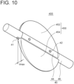
- FIG. 10 is a perspective view of a valve assembly 400 according to an embodiment.
- FIG. 11A is a partial cross-sectional view showing a structure in a bore of a throttle device 500 according to an embodiment, where a cross-section of the throttle device 500 taken along a plane perpendicular to the extension direction of a throttle shaft 40 is viewed from the extension direction of the throttle shaft 40.
- FIG. 11B is a partial cross-sectional view showing a structure in a bore of a throttle device 600 according to another embodiment, where a cross-section of the throttle device 600 taken along a plane perpendicular to the extension direction of a throttle shaft 40 is viewed from the extension direction of the throttle shaft 40.
- FIGs. 10 to 11B the configurations of the throttle body 20 and the throttle shaft 40 are the same as those described above with reference to FIGs. 2 to 6B , and the connection structure between the throttle device 500, 600 and the intake part 110 is the same as those described above with reference to FIGs. 7 to 9 .
- the throttle valve 450 includes a first portion 452 and a second portion 454 thicker than the first portion 452.
- the second portion 454 of the throttle valve 450 has a streamlined profile that decreases in thickness with increasing distance from the throttle shaft 40.
- the turbulence of intake air flow in the bore 12 due to the throttle shaft 40 and the throttle valve 450 can be suppressed, and the resistance of the intake flow path in the bore 12 can be reduced.
- the first portion 452 is set to have a thickness that allows it to pass through the slit 41 of the throttle shaft 40. That is, the thickness of the first portion 452 is equal to or smaller than the slit width of the slit 41.
- the thickness of the second portion 454 has a maximum thickness larger than the slit width of the slit 41.
- the second portion 454 having a streamlined profile should be disposed downstream of the throttle shaft 40.
- the throttle valve 450 should be oriented such that the second portion 454 is disposed on the second end surface 22 side of the throttle shaft 40 on the plane P in the fully open position.
- the first portion 452 is disposed on the first end surface 21 side of the throttle shaft 40, and the second portion 454 is disposed on the second end surface 22 side of the throttle shaft 40.
- the throttle valve 450 is inserted into the bore 12 from the second open end 16 with a narrow flow-path cross-sectional area, and the first portion 452 is inserted into the slit 41 of the throttle shaft 40.
- the contact between the throttle valve 450 and the inner surface of the bore 12 can be a problem, but since the inner surface of the bore 12 has the grooves 24 that run from the through holes 18 to the edge of the second open end 16, the grooves 24 avoid the contact between the throttle valve 450 and the inner surface of the bore 12.
- the width w of the pair of grooves 24 is larger than the maximum thickness tmax of the second portion 454 of the throttle valve 450.
- the width w of each groove 24 is constant at any longitudinal position x of the groove 24 along the center axis O of the bore 12.
- the width w of each groove 24 monotonously increases from the first end surface 21 to the second end surface 22.
- the width w of the groove 24 at the connection position with the through hole 18 i.e., the minimum value of width w of the groove 24
- the maximum thickness tmax of the second portion 454 of the throttle valve 50 is larger than the maximum thickness tmax of the second portion 454 of the throttle valve 50.
- the end portion (outer edge portion) of the second portion 454 of the throttle valve 450 can be inserted into the grooves 24, making it easier to avoid the contact between the throttle valve 450 and the inner surface of the bore 12.
- an expression of relative or absolute arrangement such as “in a direction”, “along a direction”, “parallel”, “orthogonal”, “centered”, “concentric” and “coaxial” shall not be construed as indicating only the arrangement in a strict literal sense, but also includes a state where the arrangement is relatively displaced by a tolerance, or by an angle or a distance whereby it is possible to achieve the same function.
- an expression of an equal state such as “same” “equal” and “uniform” shall not be construed as indicating only the state in which the feature is strictly equal, but also includes a state in which there is a tolerance or a difference that can still achieve the same function.
- an expression of a shape such as a rectangular shape or a cylindrical shape shall not be construed as only the geometrically strict shape, but also includes a shape with unevenness or chamfered corners within the range in which the same effect can be achieved.
Landscapes
- Engineering & Computer Science (AREA)
- Chemical & Material Sciences (AREA)
- Combustion & Propulsion (AREA)
- Mechanical Engineering (AREA)
- General Engineering & Computer Science (AREA)
- Manufacturing & Machinery (AREA)
- Control Of Throttle Valves Provided In The Intake System Or In The Exhaust System (AREA)
Abstract
Description
- The present disclosure relates to a throttle device and an intake assembly.
- Conventionally, a throttle device provided in an intake passage of an internal combustion engine for adjusting the flow rate of intake air is known.
- Atypical throttle device has a throttle shaft rotatably provided in a bore of a throttle body, and a throttle valve fixed to the throttle shaft. The throttle valve is opened and closed as the throttle shaft rotates.
- Patent Document 1 describes a throttle device in which a diffuser is provided downstream of the throttle body. The diffuser has a flow-path cross-sectional area that expands downstream. Downstream of the throttle shaft, a straightening protrusion formed to protrude inward from the inner surface of the throttle body is provided. The straightening protrusion has a valve insertion groove into which the throttle valve can be inserted from the diffuser side.
- The throttle device is assembled by rotatably attaching the throttle shaft to the throttle body and then attaching the throttle valve to the throttle shaft from upstream or downstream of the bore.
- Patent Document 1:
JP2000-179364A - When assembling the throttle valve to the throttle shaft, it is necessary to insert the throttle valve into the bore and move the throttle valve within the bore toward the throttle shaft. At this time, the maximum diameter portion of the throttle valve may come into contact with the inner surface of the bore, making it difficult to efficiently assemble the throttle valve.
- In particular, when the flow-path cross-sectional area of the intake flow path decreases at least partially from a first open end to a second open end of the bore, it is difficult to assemble the throttle valve to the throttle shaft from the second open end.
- In this regard, if a valve insertion groove is provided on the inner surface of the bore as in the throttle device described in Patent Document 1, the assembly of the throttle valve becomes easier, but the valve insertion groove increases the flow path resistance in the bore.
- In view of the above circumstances, an object of at least one embodiment of the present invention is to provide a throttle device and an intake assembly that facilitate the assembly of the throttle valve and suppress an increase in the flow path resistance in the bore.
- (1) A throttle device according to at least some embodiments of the present invention includes: a throttle body having a first end surface, a second end surface opposite to the first end surface, and a bore opening to the first end surface and the second end surface; a throttle shaft disposed rotatably within the bore; and a throttle valve fixed to the throttle shaft so as to be located at least partially within the bore. The bore has an inner surface defining an intake flow path that decreases in flow-path cross-sectional area at least partially from a first open end of the bore on the first end surface to a second open end of the bore on the second end surface. The inner surface of the bore has: a pair of through holes through which the throttle shaft passes; and a pair of grooves that run from each of the through holes to an edge of the second open end.
- (2) In some embodiments, in the above configuration (1), the pair of grooves extend along line segments where a plane including a center axis of the bore and a rotation center axis of the throttle shaft intersects the inner surface of the bore.
- (3) In some embodiments, in the above configuration (1) or (2), L-d < Dmax < L is satisfied, where Dmax is a maximum dimension of the throttle valve along an extension direction of the throttle shaft, L is a distance between bottom surfaces of the pair of grooves on the second end surface, and d is a total depth of the pair of grooves on the second end surface.
- (4) In some embodiments, in any one of the above configurations (1) to (3), the throttle valve includes: a first portion disposed on a first end surface side of the throttle shaft when the throttle valve is fully open; and a second portion thicker than the first portion and disposed on a second end surface side of the throttle shaft when the throttle valve is fully open. A width of each of the grooves is larger than a thickness of an end portion of the second portion on a side of the throttle shaft.
- (5) In an embodiment, in the above configuration (4), the second portion has a streamlined profile that decreases in thickness with increasing distance from the throttle shaft.
- (6) An intake assembly according to at least some embodiments of the present invention includes: the throttle device according to any one of the above configurations (1) to (5); and an intake part connected to the throttle body at the second end surface and having an intake passage communicating with the intake flow path formed by the bore. The intake part includes a pair of protrusions protruding toward the throttle body. The pair of protrusions are configured to fit into the pair of grooves when the intake part is connected to the second end surface of the throttle body.
- (7) In some embodiments, in the above configuration (6), each protrusion has a flow path forming surface that forms a flow path wall of the intake flow path along the inner surface of the bore around each groove.
- (8) In some embodiments, in the above configuration (6) or (7), each protrusion has a tapered shape corresponding to each groove that decreases in groove width from the second end surface toward the through hole.
- According to at least some embodiments of the present invention, by moving the throttle valve in the bore along the grooves that run from the through holes, through which the throttle shaft passes, to the edge of the second open end of the bore, the throttle valve can be easily assembled from the second end surface of the throttle body.
- Further, by closing the grooves with the protrusions of the intake part connected to the throttle device at the second end surface, the increase in flow path resistance in the bore can be suppressed.
-
-
FIG. 1 is a configuration diagram of an intake assembly according to an embodiment. -
FIG. 2 is a cross-sectional view of a throttle device according to an embodiment. -
FIG. 3 is a partial cross-sectional view of a throttle device according to an embodiment. -
FIG. 4 is a partial cross-sectional view of a throttle body according to an embodiment. -
FIG. 5 is a perspective view of a throttle device according to an embodiment. -
FIG. 6A is a partial cross-sectional view showing a structure in a bore of a throttle device according to an embodiment. -
FIG. 6B is a partial cross-sectional view showing a structure in a bore of a throttle device according to another embodiment. -
FIG. 7 is a perspective view of an intake part according to an embodiment. -
FIG. 8 is a perspective view of an internal structure of an intake part and a throttle body according to an embodiment. -
FIG. 9 is a schematic view of a cross-section of an intake part and a throttle body according to an embodiment. -
FIG. 10 is a perspective view of a valve assembly according to an embodiment. -
FIG. 11A is a partial cross-sectional view of a structure in a bore of a throttle device according to an embodiment. -
FIG. 11B is a partial cross-sectional view of a structure in a bore of a throttle device according to another embodiment. - Embodiments of the present invention will now be described in detail with reference to the accompanying drawings. It is intended, however, that unless particularly identified, dimensions, materials, shapes, relative positions, and the like of components described in the embodiments shall be interpreted as illustrative only and not intended to limit the scope of the present invention.
-
FIG. 1 is a configuration diagram of an intake assembly according to an embodiment. - As illustrated in the figure, an
intake assembly 100 includes athrottle device 10 having abore 12 that forms anintake flow path 13, and anintake part 110 having anintake passage 113 that communicates with theintake flow path 13. Theintake passage 113 is formed by aninternal flow path 112 of theintake part 110. - The
intake part 110 may be an intake boot or an intake manifold. The material of theintake part 110 may be resin, rubber, or metal. Theintake part 110 made of rubber can suppress vibration transmitted to thethrottle device 10. - In the exemplary embodiment shown in
FIG. 1 , theintake assembly 100 includes, in addition to thethrottle device 10 and theintake part 110, anotherintake part 150 located on the opposite side of thethrottle device 10 from theintake part 110. - The
intake assembly 100 constitutes an intake system for anengine 300. - In the embodiment shown in
FIG. 1 , theengine 300 includes acylinder 302 and apiston 304 that reciprocates within thecylinder 302. A cylinder block having thecylinder 302 is provided with anintake valve 320. Theintake valve 320 opens and closes in conjunction with the reciprocating motion of thepiston 304, thereby switching the supply state of the air-fuel mixture to thecylinder 302. Afuel injection device 310 for injecting fuel into theintake passage 113 is provided upstream of theintake valve 320 and downstream of avalve assembly 30, which will be described later. Fuel injected from thefuel injection device 310 is mixed with intake air flowing through theintake assembly 100 and supplied to thecylinder 302 as the air-fuel mixture. - The
piston 304 is pushed down by energy generated by combustion of the air-fuel mixture taken into thecylinder 302 via theintake valve 320. The reciprocating motion of thepiston 304 is transmitted to acrankshaft 308 via a connectingrod 306. - The
throttle device 10 includes athrottle body 20 having abore 12 and avalve assembly 30 disposed within thebore 12. - The
throttle body 20 has afirst end surface 21 and asecond end surface 22 through which thebore 12 opens. Thefirst end surface 21 and thesecond end surface 22 are both end surfaces of thethrottle body 20 in the flow direction of intake air (the direction of the center axis of the bore 12), and thesecond end surface 22 is opposite to thefirst end surface 21. - The
valve assembly 30 is provided in theintake flow path 13 communicating with theintake passage 113 of theintake part 110 and is used to adjust the amount of intake air. - The
valve assembly 30 includes athrottle shaft 40 rotatably disposed within thebore 12 and athrottle valve 50 fixed to thethrottle shaft 40 so as to be located at least partially within thebore 12. Thethrottle valve 50 is opened and closed by rotating around the central axis of thethrottle shaft 40 as thethrottle shaft 40 rotates. Specifically, thethrottle valve 50 can be switched from a closed position, where the valve is oriented perpendicular to the intake air flow, to an open position, where the valve is oriented along the intake air flow, by turning 90 degrees in the direction of arrow A with the rotation of thethrottle shaft 40.FIG. 1 shows thethrottle valve 50 in a substantially closed position. - The specific configuration of the
valve assembly 30 will be described later in detail. - The
intake part 110 is connected to thethrottle device 10. Thesecond end surface 22 of thethrottle body 20 is a contact surface with theintake part 110. In other words, theintake part 110 is connected to thethrottle body 20 at thesecond end surface 22. - As will be described later in detail, a
groove 24 is formed on the inner surface of thebore 12 of thethrottle body 20. Thegroove 24 of thethrottle body 20 may have a shape complementary to aprotrusion 114 provided on theintake part 110. In this case, when theintake part 110 is assembled to thethrottle device 10, theprotrusion 114 of theintake part 110 may fit into thegroove 24. - In the exemplary embodiment shown in
FIG. 1 , theother intake part 150 is disposed upstream of thethrottle device 10, and theintake part 110 is disposed downstream of thethrottle device 10. - In this case, the
first end surface 21 connected to theother intake part 150 is an upstream end surface of thethrottle body 20 in the intake air flow direction, and thesecond end surface 22 connected to theintake part 110 is a downstream end surface of thethrottle body 20 in the intake air flow direction. - Hereinafter, the
throttle device 10 according to some embodiments will be described with reference toFIGs. 2 to 6B . -
FIG. 2 is a cross-sectional view of thethrottle device 10 according to an embodiment, showing a cross-section of thethrottle device 10 taken along the extension direction of thethrottle shaft 40.FIG. 3 is a partial cross-sectional view of thethrottle device 10 according to an embodiment, with a portion of thethrottle body 20 cut open to expose thevalve assembly 30.FIG. 4 is a partial cross-sectional view of thethrottle body 20 according to an embodiment, with thevalve assembly 30 removed fromFIG. 3 .FIG. 5 is a perspective view of thethrottle device 10 according to an embodiment, as viewed from thesecond end surface 22. -
FIG. 6A is a partial cross-sectional view showing a structure in the bore of thethrottle device 10 according to an embodiment, where a cross-section of thethrottle device 10 taken along a plane perpendicular to the extension direction of thethrottle shaft 40 is viewed from the extension direction of thethrottle shaft 40.FIG. 6B is a partial cross-sectional view showing a structure in the bore of thethrottle device 10 according to another embodiment, where a cross-section of thethrottle device 10 taken along a plane perpendicular to the extension direction of thethrottle shaft 40 is viewed from the extension direction of thethrottle shaft 40. - As shown in
FIGs. 2 to 5 , in some embodiments, thethrottle device 10 includes athrottle body 20, and avalve assembly 30 for adjusting the flow rate of intake air passing through anintake flow path 13 formed in thethrottle body 20. - The
throttle body 20 has abore 12. Thebore 12 has a firstopen end 14 on thefirst end surface 21 of thethrottle body 20 and a secondopen end 16 on thesecond end surface 22 of thethrottle body 20. - The cross-sectional shape of the
bore 12 is not limited, but may be circular, oval, or a shape with a profile defined by a curve combining multiple arcs. - The
intake flow path 13 formed by the inner surface of thebore 12 decreases in flow-path cross-sectional area at least partially from the firstopen end 14 to the secondopen end 16 of thebore 12. - In an embodiment, the flow-path cross-sectional area of the
intake flow path 13 decreases continuously over the entire section of theintake flow path 13 from the firstopen end 14 to the secondopen end 16. In another embodiment, theintake flow path 13 has a section where the flow-path cross-sectional area of theintake flow path 13 is constant and a section where the flow-path cross-sectional area of theintake flow path 13 decreases from the firstopen end 14 to the secondopen end 16. - The inner surface of the
bore 12 may at least partially have a tapered shape that is oblique to the center axis O of the bore 12 (seeFIGs. 2 and4 ). Specifically, thebore 12 may have a tapered inner surface that is oblique to the center axis O so that the inner diameter of thebore 12 decreases from the firstopen end 14 to the secondopen end 16. - In the exemplary embodiment shown in
FIGs. 3 and4 , thebore 12 has the above-described tapered inner surface along the entire length of thebore 12 from the firstopen end 14 to the secondopen end 16. In another embodiment, the inner surface of thebore 12 includes a straight portion with a constant inner diameter and the above-described tapered portion with a varying inner diameter. - As shown in
FIG. 2 , thethrottle body 20 has a pair of throughholes 18 passing through thethrottle body 20 in the extension direction of thethrottle shaft 40. Both end portions of thethrottle shaft 40 are inserted into the pair of throughholes 18, respectively. - As shown in
FIGs. 3 to 5 , each throughhole 18 opens to the inner surface of thebore 12. - In some embodiments, the inner surface of the
bore 12 has, in addition to the pair of throughholes 18, a pair ofgrooves 24 leading to the respective throughholes 18. - Each
groove 24 runs continuously from the corresponding throughhole 18 to the edge of the secondopen end 16 of thebore 12. That is, one end of thegroove 24 opens to the throughhole 18, and the other end of thegroove 24 opens to thesecond end surface 22 of thethrottle body 20. - As shown in
FIGs. 3 ,4 ,6A, and 6B , the pair ofgrooves 24 extend alongline segments 19 where a plane P including the center axis O of thebore 12 and the rotation center axis R of thethrottle shaft 40 intersects the inner surface of thebore 12. In other words, eachgroove 24 is provided on the plane P. - In some embodiments, as shown in
FIGs. 3 ,6A, and 6B , thethrottle valve 50 in the fully open position is on the plane P. In this case, the pair ofgrooves 24 continuously extend from the throughholes 18 to the edge of the secondopen end 16 along the fullyopen throttle valve 50. - The depth of the
grooves 24 is determined in consideration of the maximum dimension Dmax of thethrottle valve 50 along the extension direction of thethrottle shaft 40. Specifically, as shown inFIG. 2 , the depth of the pair ofgrooves 24 is determined such that the total d (= d1 + d2) of the depths d1, d2 of thegrooves 24 on thesecond end surface 22 satisfies L-d < Dmax < L, where L is a distance between bottom surfaces 25 of the pair ofgrooves 24 on thesecond end surface 22. - In some embodiments, at any longitudinal position x of the
grooves 24 along the center axis O of thebore 12, the total depth d(x) of thegrooves 24 at that position satisfies L(x)-d < Dmax < L(x), where L(x) is a distance between the bottom surfaces 25 of the pair ofgrooves 24 at that position. Here, both d(x) and L(x) are meant to be functions of the longitudinal position x of thegrooves 24. - In the exemplary embodiment shown in
FIG. 2 , thebottom surface 25 of eachgroove 24 is a plane along the center axis O of thebore 12, and the distance L(x) between the bottom surfaces 25 of the pair ofgrooves 24 is constant at any longitudinal position x. - In some embodiments, as shown in
FIGs. 3 and5 to 6B , thethrottle shaft 40 includes aslit 41 into which thethrottle valve 50 can be inserted, and afastener 42 for fastening thethrottle valve 50 inserted into theslit 41. - The shape of the
slit 41 is not particularly limited as long as thethrottle valve 50 can be inserted. In the examples shown inFIGs. 3 and5 to 6B , theslit 41 has a rectangular cross-sectional shape, where the slit width of theslit 41 corresponds to the thickness of thethrottle valve 50, and the slit length of theslit 41 is larger than the maximum dimension Dmax of thethrottle valve 50. Here, the slit length of theslit 41 means the length of theslit 41 in the extension direction of thethrottle shaft 40. - The
fastener 42 may include a bolt or a screw that passes through a through hole (not shown) provided in thethrottle valve 50. In this case, thethrottle shaft 40 may have a female threaded hole into which thefastener 42, such as a bolt or a screw, is screwed. - In some embodiments, as shown in
FIGs. 3 and5 , thethrottle shaft 40 has aflat surface 44 at least in the position of thethrottle valve 50 fastened by thefastener 42. - The
flat surface 44 may be a plane along the extension direction of thethrottle valve 50. In this case, theflat surface 44 may be parallel to the plane P when thethrottle valve 50 is fully open, as shown inFIGs. 6A and 6B . - In the exemplary embodiments shown in
FIGs. 3 and5 to 6B , the portion of thethrottle shaft 40 exposed to theintake flow path 13 formed by thebore 12 has theflat surface 44. On the other hand, the portion of thethrottle shaft 40 inserted into the throughhole 18 formed in thethrottle body 20 has a cylindrical shape. - The thickness of the
throttle valve 50 is set so as to satisfy a predetermined relationship with the width of the pair ofgrooves 24. - In some embodiments, as shown in
FIGs. 6A and 6B , the width w of eachgroove 24 is larger than the thickness t of thethrottle valve 50. In the example shown inFIG. 6A , the width w of eachgroove 24 is constant for any longitudinal position x of thegroove 24 along the center axis O of thebore 12. In contrast, in the example shown inFIG. 6B , the width w of eachgroove 24 monotonously increases from thefirst end surface 21 to thesecond end surface 22. In the example shown inFIG. 6B , the width w of thegroove 24 at the connection position with the through hole 18 (i.e., the minimum value of width w of the groove 24) is larger than the thickness t of thethrottle valve 50. -
FIGs. 3 to 6B show an example of thethrottle valve 50 with a constant thickness t at any position, but the thickness of thethrottle valve 50 may vary with position. In this case, the width w of eachgroove 24 may be determined based on the thickness t of the outer edge of thethrottle valve 50 along the extension direction of thethrottle shaft 40. That is, the width w of eachgroove 24 may be set to be larger than the thickness t of the portion (outer edge portion) of thethrottle valve 50 inserted into the correspondinggroove 24 or the portion (outer edge portion) of thethrottle valve 50 closest to the correspondinggroove 24. - With the
throttle device 10 according to the embodiments described with reference toFIGs. 2 to 6B , since thegrooves 24 run from each of the throughholes 18 to the edge of the secondopen end 16 of thebore 12 where the flow-path cross-sectional area of theintake flow path 13 is relatively small, the assembly of thethrottle valve 50 to thethrottle shaft 40 from thesecond end surface 22 becomes easy. That is, by moving thethrottle valve 50 in thebore 12 along thegrooves 24 that run from the throughholes 18, through which thethrottle shaft 40 passes, to the edge of the secondopen end 16 of thebore 12, thethrottle valve 50 can be easily assembled from thesecond end surface 22 of thethrottle body 20. - Additionally, the
grooves 24 on the inner surface of thebore 12 run from the throughholes 18 to the edge of the secondopen end 16. Accordingly, by closing thegrooves 24 with the protrusions 114 (seeFIG. 1 ) of theintake part 110 connected to thethrottle device 10 at thesecond end surface 22, the increase in flow path resistance in thebore 12 can be suppressed. - Further, the pair of
grooves 24 extend along theline segments 19 where the plane P including the center axis O of thebore 12 and the rotation center axis R of thethrottle shaft 40 intersects the inner surface of thebore 12. Accordingly, by linearly moving thethrottle valve 50 in thebore 12 along the grooves 24 (along the plane P) while keeping the orientation of thethrottle valve 50 in the fully open position (FIGs. 3 and5 to 6B ), thethrottle valve 50 can be easily assembled to thethrottle shaft 40. - Further, in the embodiment described with reference to
FIG. 2 , L-d < Dmax < L is satisfied, where Dmax is the maximum dimension of thethrottle valve 50 along the extension direction of thethrottle shaft 40, L is the distance between the bottom surfaces 25 of the pair ofgrooves 24 on thesecond end surface 22, and d is the total depth of the pair ofgrooves 24 on thesecond end surface 22. In this case, by inserting the outer edge portion of thethrottle valve 50 into thegrooves 24 provided on the inner surface of thebore 12, contact between the inner surface of thebore 12 and thethrottle valve 50 can be avoided when assembling thethrottle valve 50. - Next, a connection structure between the
throttle device 10 and theintake part 110 according to some embodiments will be described with reference toFIGs. 7 to 9 . -
FIG. 7 is a perspective view of theintake part 110 according to an embodiment.FIG. 8 is a perspective view of an internal structure of theintake part 110 and thethrottle body 20 according to an embodiment, with theintake part 110 and thethrottle body 20 cut open to show the inside of theintake flow path 13 and theintake passage 113.FIG. 9 is a schematic view of a cross-section of theintake part 110 and thethrottle body 20 according to an embodiment. - In some embodiments, as shown in
FIG. 7 , theintake part 110 includes acontact surface 116 that contacts thesecond end surface 22 of thethrottle body 20, and a pair ofprotrusions 114 that protrude from thecontact surface 116 toward thethrottle body 20 along the plane P. - Each
protrusion 114 has a flowpath forming surface 115 continuously connected to a flow path wall of theinternal flow path 112 of theintake part 110 forming theintake passage 113. The flowpath forming surfaces 115 of the pair ofprotrusions 114 are arranged to face each other with theintake passage 113 interposed therebetween. - As shown in
FIG. 7 , when theintake part 110 is assembled to thethrottle device 10, eachprotrusion 114 is located on anintersection line 117 between thecontact surface 116 and the plane P (seeFIGs. 3 ,4 ,6A and 6B ) including the center axis O of thebore 12 and the rotation center axis R of thethrottle shaft 40. - Therefore, as shown in
FIGs. 8 and9 , the pair ofprotrusions 114 are fitted into thegrooves 24 of thethrottle body 20 when theintake part 110 is assembled to thethrottle device 10. - Thus, by fitting the
protrusions 114 of theintake part 110 connected to thesecond end surface 22 of thethrottle body 20 into thegrooves 24 on the inner surface of thebore 12, the step of the flow path wall caused by thegrooves 24 is reduced, and the increase in flow path resistance in thebore 12 can be suppressed. - In some embodiments, as shown in
FIGs. 8 and9 , the flowpath forming surface 115 of eachprotrusion 114 forms the flow path wall of theintake flow path 13 along the inner surface of thebore 12 around eachgroove 24. - In this case, the turbulence of intake air flow in the
intake flow path 13 can be suppressed more effectively, and the flow path resistance in thebore 12 can be reduced. - Each
protrusion 114 has a shape corresponding to thegroove 24 to be fitted. - In the exemplary embodiment shown in
FIGs. 7 and8 , eachprotrusion 114 has a tapered shape corresponding to each groove 24 (seeFIG. 6B ) that decreases in groove width w from thesecond end surface 22 to the throughhole 18. - In this case, when assembling the
intake part 110 to thethrottle device 10, the taperedprotrusion 114 can be easily fitted into thegroove 24. - In another embodiment, each
protrusion 114 has a straight shape corresponding to thegroove 24 with a constant groove width w over the entire length of thegroove 24 from thesecond end surface 22 to the throughhole 18. - Some embodiments have been described above, but modifications may be made to the above-described embodiments without departing from the spirit of the present invention.
- For example, the above-described embodiments mainly describe the
throttle device 10 including thethrottle valve 50 of a flat plate shape with a constant thickness in any position, but the shape of the throttle valve is not limited to this example. -
FIG. 10 is a perspective view of avalve assembly 400 according to an embodiment. -
FIG. 11A is a partial cross-sectional view showing a structure in a bore of athrottle device 500 according to an embodiment, where a cross-section of thethrottle device 500 taken along a plane perpendicular to the extension direction of athrottle shaft 40 is viewed from the extension direction of thethrottle shaft 40.FIG. 11B is a partial cross-sectional view showing a structure in a bore of athrottle device 600 according to another embodiment, where a cross-section of thethrottle device 600 taken along a plane perpendicular to the extension direction of athrottle shaft 40 is viewed from the extension direction of thethrottle shaft 40. - In
FIGs. 10 to 11B , the configurations of thethrottle body 20 and thethrottle shaft 40 are the same as those described above with reference toFIGs. 2 to 6B , and the connection structure between thethrottle device intake part 110 is the same as those described above with reference toFIGs. 7 to 9 . - Therefore, the configuration of a
throttle valve 450 will be mainly described below. - In some embodiments, as shown in
FIGs. 10 to 11B , thethrottle valve 450 includes afirst portion 452 and asecond portion 454 thicker than thefirst portion 452. - In the exemplary embodiments shown in
FIGs. 10 to 11B , thesecond portion 454 of thethrottle valve 450 has a streamlined profile that decreases in thickness with increasing distance from thethrottle shaft 40. - In this case, the turbulence of intake air flow in the
bore 12 due to thethrottle shaft 40 and thethrottle valve 450 can be suppressed, and the resistance of the intake flow path in thebore 12 can be reduced. - The
first portion 452 is set to have a thickness that allows it to pass through theslit 41 of thethrottle shaft 40. That is, the thickness of thefirst portion 452 is equal to or smaller than the slit width of theslit 41. - On the other hand, the thickness of the
second portion 454 has a maximum thickness larger than the slit width of theslit 41. As shown inFIGs. 10 to 11B , when thesecond portion 454 has a streamlined profile that decreases in thickness with increasing distance from thethrottle shaft 40, the thickness of thesecond portion 454 reaches the maximum value (=t max) at the end portion on thethrottle shaft 40 side. In this example, the thickness (= tmax) of the end portion of thesecond portion 454 on thethrottle shaft 40 side is larger than the slit width of theslit 41. - Assuming the intake air flow in the
bore 12 from the firstopen end 14 to the secondopen end 16, in order to reduce the turbulence of intake air flow downstream of thethrottle shaft 40, thesecond portion 454 having a streamlined profile should be disposed downstream of thethrottle shaft 40. - In particular, since it is important to reduce the flow loss when the
throttle valve 450 is fully open, thethrottle valve 450 should be oriented such that thesecond portion 454 is disposed on thesecond end surface 22 side of thethrottle shaft 40 on the plane P in the fully open position. - Then, in some embodiments, as shown in
FIGs. 11A and 11B , when thethrottle valve 450 is fully open, thefirst portion 452 is disposed on thefirst end surface 21 side of thethrottle shaft 40, and thesecond portion 454 is disposed on thesecond end surface 22 side of thethrottle shaft 40. - On the other hand, in order to place the relatively thicker
second portion 454 on thesecond end surface 22 side of thethrottle shaft 40, it is necessary to mount thethrottle valve 450 to thethrottle shaft 40 from thesecond end surface 22. In this case, thethrottle valve 450 is inserted into thebore 12 from the secondopen end 16 with a narrow flow-path cross-sectional area, and thefirst portion 452 is inserted into theslit 41 of thethrottle shaft 40. - At this time, the contact between the
throttle valve 450 and the inner surface of thebore 12 can be a problem, but since the inner surface of thebore 12 has thegrooves 24 that run from the throughholes 18 to the edge of the secondopen end 16, thegrooves 24 avoid the contact between thethrottle valve 450 and the inner surface of thebore 12. - In some embodiments, as shown in
FIGs. 11A and 11B , the width w of the pair ofgrooves 24 is larger than the maximum thickness tmax of thesecond portion 454 of thethrottle valve 450. - In the example shown in
FIG. 11A , the width w of eachgroove 24 is constant at any longitudinal position x of thegroove 24 along the center axis O of thebore 12. In contrast, in the example shown inFIG. 11B , the width w of eachgroove 24 monotonously increases from thefirst end surface 21 to thesecond end surface 22. In the example shown inFIG. 11B , the width w of thegroove 24 at the connection position with the through hole 18 (i.e., the minimum value of width w of the groove 24) is larger than the maximum thickness tmax of thesecond portion 454 of thethrottle valve 50. - With the above configuration, when the
throttle valve 450 with thesecond portion 454 thicker than thefirst portion 452 is assembled to thethrottle shaft 40 from the secondopen end 16 of thebore 12, the end portion (outer edge portion) of thesecond portion 454 of thethrottle valve 450 can be inserted into thegrooves 24, making it easier to avoid the contact between thethrottle valve 450 and the inner surface of thebore 12. - Further, in the present specification, an expression of relative or absolute arrangement such as "in a direction", "along a direction", "parallel", "orthogonal", "centered", "concentric" and "coaxial" shall not be construed as indicating only the arrangement in a strict literal sense, but also includes a state where the arrangement is relatively displaced by a tolerance, or by an angle or a distance whereby it is possible to achieve the same function.
- For instance, an expression of an equal state such as "same" "equal" and "uniform" shall not be construed as indicating only the state in which the feature is strictly equal, but also includes a state in which there is a tolerance or a difference that can still achieve the same function.
- Further, an expression of a shape such as a rectangular shape or a cylindrical shape shall not be construed as only the geometrically strict shape, but also includes a shape with unevenness or chamfered corners within the range in which the same effect can be achieved.
- On the other hand, an expression such as "comprise", "include", and "have" are not intended to be exclusive of other components.
Claims (8)
- A throttle device, comprising:a throttle body having a first end surface, a second end surface opposite to the first end surface, and a bore opening to the first end surface and the second end surface;a throttle shaft disposed rotatably within the bore; anda throttle valve fixed to the throttle shaft so as to be located at least partially within the bore,wherein the bore has an inner surface defining an intake flow path that decreases in flow-path cross-sectional area at least partially from a first open end of the bore on the first end surface to a second open end of the bore on the second end surface, andwherein the inner surface of the bore has:a pair of through holes through which the throttle shaft passes; anda pair of grooves that run from each of the through holes to an edge of the second open end.
- The throttle device according to claim 1,
wherein the pair of grooves extend along line segments where a plane including a center axis of the bore and a rotation center axis of the throttle shaft intersects the inner surface of the bore. - The throttle device according to claim 1 or 2,
wherein L-d < Dmax < L is satisfied, where Dmax is a maximum dimension of the throttle valve along an extension direction of the throttle shaft, L is a distance between bottom surfaces of the pair of grooves on the second end surface, and d is a total depth of the pair of grooves on the second end surface. - The throttle device according to any one of claims 1 to 3,wherein the throttle valve includes:a first portion disposed on a first end surface side of the throttle shaft when the throttle valve is fully open; anda second portion thicker than the first portion and disposed on a second end surface side of the throttle shaft when the throttle valve is fully open, andwherein a width of each of the grooves is larger than a thickness of an end portion of the second portion on a side of the throttle shaft.
- The throttle device according to claim 4,
wherein the second portion has a streamlined profile that decreases in thickness with increasing distance from the throttle shaft. - An intake assembly, comprising:the throttle device according to any one of claims 1 to 5; andan intake part connected to the throttle body at the second end surface and having an intake passage communicating with the intake flow path formed by the bore,wherein the intake part includes a pair of protrusions protruding toward the throttle body, andwherein the pair of protrusions are configured to fit into the pair of grooves when the intake part is connected to the second end surface of the throttle body.
- The intake assembly according to claim 6,
wherein each protrusion has a flow path forming surface that forms a flow path wall of the intake flow path along the inner surface of the bore around each groove. - The intake assembly according to claim 6 or 7,
wherein each protrusion has a tapered shape corresponding to each groove that decreases in groove width from the second end surface toward the through hole.
Applications Claiming Priority (1)
| Application Number | Priority Date | Filing Date | Title |
|---|---|---|---|
| JP2022025291A JP7767179B2 (en) | 2022-02-22 | 2022-02-22 | Intake Assembly |
Publications (2)
| Publication Number | Publication Date |
|---|---|
| EP4230857A1 true EP4230857A1 (en) | 2023-08-23 |
| EP4230857B1 EP4230857B1 (en) | 2026-02-04 |
Family
ID=84519735
Family Applications (1)
| Application Number | Title | Priority Date | Filing Date |
|---|---|---|---|
| EP22213104.7A Active EP4230857B1 (en) | 2022-02-22 | 2022-12-13 | Throttle device and intake assembly |
Country Status (2)
| Country | Link |
|---|---|
| EP (1) | EP4230857B1 (en) |
| JP (1) | JP7767179B2 (en) |
Citations (7)
| Publication number | Priority date | Publication date | Assignee | Title |
|---|---|---|---|---|
| JPH04134140A (en) * | 1990-09-27 | 1992-05-08 | Fuji Oozx Kk | Butterfly type exhaust valve |
| US5329903A (en) * | 1991-11-05 | 1994-07-19 | Filterwerk Mann & Hummel Gmbh | Pivotable joint |
| JPH09133224A (en) * | 1995-11-02 | 1997-05-20 | Ngk Insulators Ltd | Butterfly valve for high-temperature fluid |
| JPH11351416A (en) * | 1998-06-12 | 1999-12-24 | Aisan Ind Co Ltd | Butterfly valve device and method for assembling butterfly valve |
| JP2000179364A (en) | 1998-12-15 | 2000-06-27 | Aisan Ind Co Ltd | Throttle body having diffuser |
| EP1213456A2 (en) * | 2000-12-05 | 2002-06-12 | Robert Bosch Gmbh | Current control unit |
| EP2881564A1 (en) * | 2013-12-04 | 2015-06-10 | Magneti Marelli S.p.A. | Throttle valve for an internal combustion engine provided with a metal valve seat overmoulded inside a valve body made of a plastic material |
Family Cites Families (5)
| Publication number | Priority date | Publication date | Assignee | Title |
|---|---|---|---|---|
| JPH07217458A (en) * | 1994-01-31 | 1995-08-15 | Jidosha Kiki Co Ltd | Butterfly valve |
| JP2009264114A (en) | 2008-04-22 | 2009-11-12 | Hitachi Ltd | Throttle valve control device of internal combustion engine |
| JP2017180439A (en) | 2016-03-31 | 2017-10-05 | 株式会社ケーヒン | Throttle device |
| JP2021021356A (en) | 2019-07-25 | 2021-02-18 | 株式会社ケーヒン | Intake control device |
| JP7566594B2 (en) | 2020-11-20 | 2024-10-15 | 株式会社ミクニ | Butterfly valve device |
-
2022
- 2022-02-22 JP JP2022025291A patent/JP7767179B2/en active Active
- 2022-12-13 EP EP22213104.7A patent/EP4230857B1/en active Active
Patent Citations (7)
| Publication number | Priority date | Publication date | Assignee | Title |
|---|---|---|---|---|
| JPH04134140A (en) * | 1990-09-27 | 1992-05-08 | Fuji Oozx Kk | Butterfly type exhaust valve |
| US5329903A (en) * | 1991-11-05 | 1994-07-19 | Filterwerk Mann & Hummel Gmbh | Pivotable joint |
| JPH09133224A (en) * | 1995-11-02 | 1997-05-20 | Ngk Insulators Ltd | Butterfly valve for high-temperature fluid |
| JPH11351416A (en) * | 1998-06-12 | 1999-12-24 | Aisan Ind Co Ltd | Butterfly valve device and method for assembling butterfly valve |
| JP2000179364A (en) | 1998-12-15 | 2000-06-27 | Aisan Ind Co Ltd | Throttle body having diffuser |
| EP1213456A2 (en) * | 2000-12-05 | 2002-06-12 | Robert Bosch Gmbh | Current control unit |
| EP2881564A1 (en) * | 2013-12-04 | 2015-06-10 | Magneti Marelli S.p.A. | Throttle valve for an internal combustion engine provided with a metal valve seat overmoulded inside a valve body made of a plastic material |
Also Published As
| Publication number | Publication date |
|---|---|
| JP7767179B2 (en) | 2025-11-11 |
| EP4230857B1 (en) | 2026-02-04 |
| JP2023121928A (en) | 2023-09-01 |
Similar Documents
| Publication | Publication Date | Title |
|---|---|---|
| US4907547A (en) | One-piece wave deflector for I.C. engine intake system | |
| EP3379051B1 (en) | Air intake device for internal combustion engine | |
| KR950001335B1 (en) | Fuel injection valve | |
| EP0281771B1 (en) | Temperature compensated fluid flow metering system | |
| EP4230857B1 (en) | Throttle device and intake assembly | |
| US6561160B2 (en) | Rotary-body type throttle valve for spark ignition internal combustion engine | |
| US20220163119A1 (en) | Butterfly valve device | |
| CN112855401B (en) | Limiting cap | |
| US20190301410A1 (en) | Intake port structure | |
| US10302051B2 (en) | Intake device | |
| US6622696B2 (en) | Throttle valve having a large diameter shaft with integral valve plate | |
| US12612884B2 (en) | Flow control restrictor | |
| US12480461B2 (en) | Fuel regulator | |
| JP2002227663A (en) | Gas flow control device | |
| US20210340919A1 (en) | Throttle device | |
| JPWO2011048674A1 (en) | Stratified scavenging two-cycle engine | |
| CN110312863A (en) | Fuel injection device | |
| EP0896131B1 (en) | Single-body reed valve for internal combustion engine, integrally joined with the intake pipe | |
| JPH1193802A (en) | Mounting structure of fuel supply pipe | |
| EP3301289B1 (en) | Throttle valve for an internal combustion engine | |
| JP2017075569A (en) | Intake device for internal combustion engine | |
| JPH1122569A (en) | Intake device for internal combustion engine | |
| JP2023141891A (en) | Intake manifold connection structure | |
| WO2007057034A1 (en) | Flow control device | |
| JPH0783144A (en) | Fuel injection valve and fuel injection device |
Legal Events
| Date | Code | Title | Description |
|---|---|---|---|
| PUAI | Public reference made under article 153(3) epc to a published international application that has entered the european phase |
Free format text: ORIGINAL CODE: 0009012 |
|
| STAA | Information on the status of an ep patent application or granted ep patent |
Free format text: STATUS: THE APPLICATION HAS BEEN PUBLISHED |
|
| AK | Designated contracting states |
Kind code of ref document: A1 Designated state(s): AL AT BE BG CH CY CZ DE DK EE ES FI FR GB GR HR HU IE IS IT LI LT LU LV MC ME MK MT NL NO PL PT RO RS SE SI SK SM TR |
|
| STAA | Information on the status of an ep patent application or granted ep patent |
Free format text: STATUS: REQUEST FOR EXAMINATION WAS MADE |
|
| 17P | Request for examination filed |
Effective date: 20240215 |
|
| RBV | Designated contracting states (corrected) |
Designated state(s): AL AT BE BG CH CY CZ DE DK EE ES FI FR GB GR HR HU IE IS IT LI LT LU LV MC ME MK MT NL NO PL PT RO RS SE SI SK SM TR |
|
| GRAP | Despatch of communication of intention to grant a patent |
Free format text: ORIGINAL CODE: EPIDOSNIGR1 |
|
| STAA | Information on the status of an ep patent application or granted ep patent |
Free format text: STATUS: GRANT OF PATENT IS INTENDED |
|
| RIC1 | Information provided on ipc code assigned before grant |
Ipc: F02D 9/10 20060101AFI20250909BHEP Ipc: F02D 9/02 20060101ALN20250909BHEP |
|
| RIC1 | Information provided on ipc code assigned before grant |
Ipc: F02D 9/10 20060101AFI20250915BHEP Ipc: F02D 9/02 20060101ALN20250915BHEP |
|
| INTG | Intention to grant announced |
Effective date: 20250926 |
|
| GRAS | Grant fee paid |
Free format text: ORIGINAL CODE: EPIDOSNIGR3 |
|
| GRAA | (expected) grant |
Free format text: ORIGINAL CODE: 0009210 |
|
| STAA | Information on the status of an ep patent application or granted ep patent |
Free format text: STATUS: THE PATENT HAS BEEN GRANTED |
|
| AK | Designated contracting states |
Kind code of ref document: B1 Designated state(s): AL AT BE BG CH CY CZ DE DK EE ES FI FR GB GR HR HU IE IS IT LI LT LU LV MC ME MK MT NL NO PL PT RO RS SE SI SK SM TR |
|
| REG | Reference to a national code |
Ref country code: CH Ref legal event code: F10 Free format text: ST27 STATUS EVENT CODE: U-0-0-F10-F00 (AS PROVIDED BY THE NATIONAL OFFICE) Effective date: 20260204 Ref country code: GB Ref legal event code: FG4D |
|
| REG | Reference to a national code |
Ref country code: IE Ref legal event code: FG4D |
|
| REG | Reference to a national code |
Ref country code: DE Ref legal event code: R096 Ref document number: 602022029592 Country of ref document: DE |