EP4230855A1 - Smart fuel supply system - Google Patents
Smart fuel supply system Download PDFInfo
- Publication number
- EP4230855A1 EP4230855A1 EP23153283.9A EP23153283A EP4230855A1 EP 4230855 A1 EP4230855 A1 EP 4230855A1 EP 23153283 A EP23153283 A EP 23153283A EP 4230855 A1 EP4230855 A1 EP 4230855A1
- Authority
- EP
- European Patent Office
- Prior art keywords
- pump
- supply system
- control
- fuel
- fuel supply
- Prior art date
- Legal status (The legal status is an assumption and is not a legal conclusion. Google has not performed a legal analysis and makes no representation as to the accuracy of the status listed.)
- Pending
Links
Images

Classifications
-
- F—MECHANICAL ENGINEERING; LIGHTING; HEATING; WEAPONS; BLASTING
- F02—COMBUSTION ENGINES; HOT-GAS OR COMBUSTION-PRODUCT ENGINE PLANTS
- F02C—GAS-TURBINE PLANTS; AIR INTAKES FOR JET-PROPULSION PLANTS; CONTROLLING FUEL SUPPLY IN AIR-BREATHING JET-PROPULSION PLANTS
- F02C9/00—Controlling gas-turbine plants; Controlling fuel supply in air- breathing jet-propulsion plants
- F02C9/26—Control of fuel supply
- F02C9/263—Control of fuel supply by means of fuel metering valves
-
- F—MECHANICAL ENGINEERING; LIGHTING; HEATING; WEAPONS; BLASTING
- F02—COMBUSTION ENGINES; HOT-GAS OR COMBUSTION-PRODUCT ENGINE PLANTS
- F02C—GAS-TURBINE PLANTS; AIR INTAKES FOR JET-PROPULSION PLANTS; CONTROLLING FUEL SUPPLY IN AIR-BREATHING JET-PROPULSION PLANTS
- F02C7/00—Features, components parts, details or accessories, not provided for in, or of interest apart form groups F02C1/00 - F02C6/00; Air intakes for jet-propulsion plants
- F02C7/22—Fuel supply systems
-
- F—MECHANICAL ENGINEERING; LIGHTING; HEATING; WEAPONS; BLASTING
- F02—COMBUSTION ENGINES; HOT-GAS OR COMBUSTION-PRODUCT ENGINE PLANTS
- F02C—GAS-TURBINE PLANTS; AIR INTAKES FOR JET-PROPULSION PLANTS; CONTROLLING FUEL SUPPLY IN AIR-BREATHING JET-PROPULSION PLANTS
- F02C9/00—Controlling gas-turbine plants; Controlling fuel supply in air- breathing jet-propulsion plants
- F02C9/26—Control of fuel supply
- F02C9/28—Regulating systems responsive to plant or ambient parameters, e.g. temperature, pressure, rotor speed
-
- F—MECHANICAL ENGINEERING; LIGHTING; HEATING; WEAPONS; BLASTING
- F02—COMBUSTION ENGINES; HOT-GAS OR COMBUSTION-PRODUCT ENGINE PLANTS
- F02C—GAS-TURBINE PLANTS; AIR INTAKES FOR JET-PROPULSION PLANTS; CONTROLLING FUEL SUPPLY IN AIR-BREATHING JET-PROPULSION PLANTS
- F02C9/00—Controlling gas-turbine plants; Controlling fuel supply in air- breathing jet-propulsion plants
- F02C9/26—Control of fuel supply
- F02C9/30—Control of fuel supply characterised by variable fuel pump output
-
- F—MECHANICAL ENGINEERING; LIGHTING; HEATING; WEAPONS; BLASTING
- F05—INDEXING SCHEMES RELATING TO ENGINES OR PUMPS IN VARIOUS SUBCLASSES OF CLASSES F01-F04
- F05D—INDEXING SCHEME FOR ASPECTS RELATING TO NON-POSITIVE-DISPLACEMENT MACHINES OR ENGINES, GAS-TURBINES OR JET-PROPULSION PLANTS
- F05D2270/00—Control
- F05D2270/30—Control parameters, e.g. input parameters
- F05D2270/301—Pressure
-
- F—MECHANICAL ENGINEERING; LIGHTING; HEATING; WEAPONS; BLASTING
- F05—INDEXING SCHEMES RELATING TO ENGINES OR PUMPS IN VARIOUS SUBCLASSES OF CLASSES F01-F04
- F05D—INDEXING SCHEME FOR ASPECTS RELATING TO NON-POSITIVE-DISPLACEMENT MACHINES OR ENGINES, GAS-TURBINES OR JET-PROPULSION PLANTS
- F05D2270/00—Control
- F05D2270/30—Control parameters, e.g. input parameters
- F05D2270/306—Mass flow
Definitions
- This application relates to calibration information integrated into a dedicated control for a fuel supply system.
- Gas turbine engines are typically provided with a fuel supply system that sends fuel to a combustor on the gas turbine engine.
- Gas turbine engines are also provided with a full authority digital electronic controller (“FADEC").
- FADEC full authority digital electronic controller
- the FADEC historically has provided demand information to the fuel supply system such that a desired volume of flow of fuel is sent to a combustor on the gas turbine engine and at a desired pressure.
- the FADEC is programmed to directly control a pump and/or metering valve in the fuel metering unit.
- a fuel supply system includes a pump to be connected to a fuel tank.
- a metering valve is downstream of the pump.
- a control is programmed to control at least one of the pump and metering valve.
- the control is operable to take in a flow demand signal and a fuel pressure signal from a controller associated with a gas turbine engine.
- the flow demand signal is indicative of a desired flow volume and the fuel pressure signal is indicative of a desired fuel pressure. Operation conditions are identified for the at least one of said pump and the metering valve.
- An engine with a fuel supply system is also disclosed.
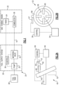
- Figure 1 shows a system 20 that incorporates a gas turbine engine 22.
- the gas turbine engine 22 has a full authority digital electronic controller (“FADEC") 24 that controls all aspects of the engine including its combustor 26.
- the gas turbine engine controller 24 takes signals from a plurality of components on the gas turbine engine and identifies a desired flow demand and fuel pressure dependent on conditions at the gas turbine engine.
- the FADEC 24 communicates with a fuel supply system 30 to demand a desired flow volume of fuel and at a desired pressure.
- Fuel tank 28 supplies fuel to a fuel pump 32 in the fuel supply system 30. Downstream of the pump 32 is a metering valve 34.
- a control 36 which is part of the fuel supply system 30, controls the pump 32 and the metering valve 34 such that a desired volume flow of fuel reaches a line 19 leading to the combustor 26. Moreover, the control 36 controls the pump 32 and metering valve 34 such that the fuel in line 19 is at a desired pressure.
- the FADEC only provides the desired volume flow and pressure to the control 36.
- the control 36 is programmed to control a variable displacement pump 32 and the metering valve 34 such that the desired volume and pressure are achieved in line 19.
- the control is supplied by the supplier of the fuel supply system 30, and is calibrated by the supplier of the pump 32 and metering valve 34. In this manner, improved accuracy is achieved.
- FIG. 2A shows a first embodiment variable displacement pump 40.
- Pump 40 incorporates a swash plate 42 having an actuator 44 that can change the eccentricity of the swash plate 42 relative to a reciprocating axis of a pump piston 48.
- the swash plate 42 is shown at a large volume flow position. However, the actuator 44 can adjust the position of the swash plate to a smaller volume position such as shown in phantom at 52.
- the piston 48 moves within a cylinder 50 to supply fuel to a downstream line 51. Although a single piston 48 is illustrated, in practice, there may a plurality of circumferentially spaced pistons 48.
- a motor 46 drives the swash plate 42 to rotate.
- a sensor 49 senses the pressure and/or volume of the fuel at line 51.
- the control 36 receives signals from the sensor 49, and operates to control the actuator 44 and motor 46 such that the swash plate 42 is operated at a desired speed and at a desired eccentricity to provide the desired flow volume and pressure to the line 51.
- the pump 40 is shown somewhat schematically, as the operation of a swash plate piston pump is known.
- FIG. 2B shows another embodiment pump 53.
- Variable displacement pump 52 is a vane pump, having a motor 54 driving a rotor 56.
- a plurality of vanes 60 are driven to move along an inner surface of a liner 58 to move fuel from an inlet to an outlet.
- the liner 58 has an actuator 57 such that the eccentricity of the liner 58 relative to a rotational axis of the rotor 56 can be controlled. In this manner the displacement of the pump can be controlled.
- This is shown schematically, as vane pumps are well known.
- Control 36 is shown here communicating with actuator 57 and motor 54 to provide the desired volume flow and pressure downstream of the pump 52.
- a sensor such as shown in Figure 2A may be provided to communicate signals back to the control 36.
- FIG. 2C shows another embodiment 70.
- Embodiment 70 includes a sharing valve 72 communicating flow to two pumps 74 and 76. While two pumps are shown, of course other plural numbers of pumps may be utilized. Pump 74 and 76 may be fixed displacement pumps. Sharing valve 72 may also send fuel into a bypass line 73 leading back to a fuel tank.
- the control 36 controls the valve 72 and the speed of the pumps 74 and 76 to provide a desired volume of flow downstream of the pump 74 and 76 to the combustor and at a desired pressure.
- the operation of such system generally is known. It is the use of the controller having calibration information to control the valve 72 and pump 74/76 which is part of this disclosure.
- a sensor such as shown in Figure 2A may be provided to communicate signals back to the control 36.
- the fuel supply system 30 is a "line replaceable" unit. That is, the fuel supply system is received within a single housing 110 that can be removed as a unit.
- the pump 32 is shown as well as a cover plate 136.
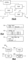
- FIG. 4 shows a flow chart.
- control 36 receives this signal and is programmed and calibrated to recognize that to achieve the flow X the pump should operate at condition A and the valve should operate at condition B.
- the control 36 is also calibrated to know that to achieve the pressure Y the pump should be operated at condition A' and the valve operated at condition B'.
- step 104 the flow downstream of the fuel supply system will be such that the flow will equal X and the pressure will equal Y.
- Figure 5 shows another embodiment 200.
- a local control 202 controls a pump 204, similar to the Figure 1 embodiment.
- control 202 still receives signals from the FADEC 206.
- the FADEC 206 directly controls the metering valve 208 in this embodiment.
- a fuel supply system includes a pump to be connected to a fuel tank.
- a metering valve is downstream of the pump.
- a control is programmed to control at least one of the pump and metering valve.
- the control is operable to take in a flow demand signal and a fuel pressure signal from a controller associated with a gas turbine engine.
- the flow demand signal is indicative of a desired flow volume and the fuel pressure signal is indicative of a desired fuel pressure.
- Operation conditions are identified for the at least one of said pump and the metering valve to achieve the desired flow volume and the desired fuel pressure.
Landscapes
- Engineering & Computer Science (AREA)
- Chemical & Material Sciences (AREA)
- Combustion & Propulsion (AREA)
- Mechanical Engineering (AREA)
- General Engineering & Computer Science (AREA)
- Feeding And Controlling Fuel (AREA)
- Control Of Positive-Displacement Pumps (AREA)
Abstract
Description
- This application relates to calibration information integrated into a dedicated control for a fuel supply system.
- Gas turbine engines are typically provided with a fuel supply system that sends fuel to a combustor on the gas turbine engine. Gas turbine engines are also provided with a full authority digital electronic controller ("FADEC").
- The FADEC historically has provided demand information to the fuel supply system such that a desired volume of flow of fuel is sent to a combustor on the gas turbine engine and at a desired pressure. The FADEC is programmed to directly control a pump and/or metering valve in the fuel metering unit.
- At times different manufacturers may manufacture the fuel supply system and the gas turbine engine.
- A fuel supply system includes a pump to be connected to a fuel tank. A metering valve is downstream of the pump. A control is programmed to control at least one of the pump and metering valve. The control is operable to take in a flow demand signal and a fuel pressure signal from a controller associated with a gas turbine engine. The flow demand signal is indicative of a desired flow volume and the fuel pressure signal is indicative of a desired fuel pressure. Operation conditions are identified for the at least one of said pump and the metering valve.
- An engine with a fuel supply system is also disclosed.
- These and other features will be best understood from the following drawings and specification, the following is a brief description.
-
-
Figure 1 schematically shows a gas turbine engine and fuel system. -
Figure 2A shows a first embodiment pump. -
Figure 2B shows a second embodiment pump. -
Figure 2C shows a third embodiment pump. -
Figure 3A shows a fuel supply system. -
Figure 3B shows a fuel supply system with a cover removed. -
Figure 4 is a flow chart of control features associated with this disclosure. -
Figure 5 shows another embodiment. -
Figure 1 shows asystem 20 that incorporates agas turbine engine 22. Thegas turbine engine 22 has a full authority digital electronic controller ("FADEC") 24 that controls all aspects of the engine including its combustor 26. The gasturbine engine controller 24 takes signals from a plurality of components on the gas turbine engine and identifies a desired flow demand and fuel pressure dependent on conditions at the gas turbine engine. The FADEC 24 communicates with afuel supply system 30 to demand a desired flow volume of fuel and at a desired pressure. -
Fuel tank 28 supplies fuel to afuel pump 32 in thefuel supply system 30. Downstream of thepump 32 is ametering valve 34. Acontrol 36, which is part of thefuel supply system 30, controls thepump 32 and themetering valve 34 such that a desired volume flow of fuel reaches aline 19 leading to the combustor 26. Moreover, thecontrol 36 controls thepump 32 andmetering valve 34 such that the fuel inline 19 is at a desired pressure. - In a feature of this disclosure, the FADEC only provides the desired volume flow and pressure to the
control 36. Thecontrol 36 is programmed to control avariable displacement pump 32 and themetering valve 34 such that the desired volume and pressure are achieved inline 19. The control is supplied by the supplier of thefuel supply system 30, and is calibrated by the supplier of thepump 32 andmetering valve 34. In this manner, improved accuracy is achieved. -
Figure 2A shows a first embodimentvariable displacement pump 40.Pump 40 incorporates aswash plate 42 having anactuator 44 that can change the eccentricity of theswash plate 42 relative to a reciprocating axis of apump piston 48. Theswash plate 42 is shown at a large volume flow position. However, theactuator 44 can adjust the position of the swash plate to a smaller volume position such as shown in phantom at 52. Thepiston 48 moves within acylinder 50 to supply fuel to a downstream line 51. Although asingle piston 48 is illustrated, in practice, there may a plurality of circumferentially spacedpistons 48. Amotor 46 drives theswash plate 42 to rotate. Asensor 49 senses the pressure and/or volume of the fuel at line 51. - The
control 36 receives signals from thesensor 49, and operates to control theactuator 44 andmotor 46 such that theswash plate 42 is operated at a desired speed and at a desired eccentricity to provide the desired flow volume and pressure to the line 51. Thepump 40 is shown somewhat schematically, as the operation of a swash plate piston pump is known. -
Figure 2B shows anotherembodiment pump 53.Variable displacement pump 52 is a vane pump, having amotor 54 driving arotor 56. As known, a plurality ofvanes 60 are driven to move along an inner surface of aliner 58 to move fuel from an inlet to an outlet. Theliner 58 has anactuator 57 such that the eccentricity of theliner 58 relative to a rotational axis of therotor 56 can be controlled. In this manner the displacement of the pump can be controlled. This is shown schematically, as vane pumps are well known. -
Control 36 is shown here communicating withactuator 57 andmotor 54 to provide the desired volume flow and pressure downstream of thepump 52. - While the sensor is not illustrated here, a sensor such as shown in
Figure 2A may be provided to communicate signals back to thecontrol 36. -
Figure 2C shows anotherembodiment 70.Embodiment 70 includes a sharingvalve 72 communicating flow to twopumps Pump valve 72 may also send fuel into abypass line 73 leading back to a fuel tank. - The
control 36 controls thevalve 72 and the speed of thepumps pump valve 72 andpump 74/76 which is part of this disclosure. - While the sensor is not illustrated here, a sensor such as shown in
Figure 2A may be provided to communicate signals back to thecontrol 36. - As shown in
Figure 3A , thefuel supply system 30 is a "line replaceable" unit. That is, the fuel supply system is received within asingle housing 110 that can be removed as a unit. Thepump 32 is shown as well as acover plate 136. - In
Figure 3B thecover plate 136 is removed and one can see thecontrol 36 is received within acompartment 140 in the line replaceablefuel metering unit 30. -
Figure 4 shows a flow chart. At step 100 a signal is received from a FADEC, and that signal is FLOW = X, PRESSURE = Y. - At
step 102 thecontrol 36 receives this signal and is programmed and calibrated to recognize that to achieve the flow X the pump should operate at condition A and the valve should operate at condition B. Thecontrol 36 is also calibrated to know that to achieve the pressure Y the pump should be operated at condition A' and the valve operated at condition B'. - At
step 104, the flow downstream of the fuel supply system will be such that the flow will equal X and the pressure will equal Y. - In sum, by moving the specific control for the fuel supply system to a dedicated controller the accuracy of the fuel downstream of the fuel supply system meeting the demanded flow and pressure requirements will be improved.
-
Figure 5 shows anotherembodiment 200. Inembodiment 200, alocal control 202 controls apump 204, similar to theFigure 1 embodiment. However,control 202 still receives signals from theFADEC 206. However, theFADEC 206 directly controls themetering valve 208 in this embodiment. - A fuel supply system includes a pump to be connected to a fuel tank. A metering valve is downstream of the pump. A control is programmed to control at least one of the pump and metering valve. The control is operable to take in a flow demand signal and a fuel pressure signal from a controller associated with a gas turbine engine. The flow demand signal is indicative of a desired flow volume and the fuel pressure signal is indicative of a desired fuel pressure. Operation conditions are identified for the at least one of said pump and the metering valve to achieve the desired flow volume and the desired fuel pressure.
- Although embodiments have been disclosed, a worker of skill in this art would recognize that modifications would come within the scope of the invention as defined by the claims.
Claims (14)
- A fuel supply system (30) comprising:a pump (32) to be connected to a fuel tank (28), a metering valve (34) downstream of said pump; anda control (36), said control programmed to control at least one of said pump and metering valve, said control operable to take in a flow demand signal and a fuel pressure signal from a controller associated with a gas turbine engine, the flow demand signal being indicative of a desired flow volume and the fuel pressure signal being indicative of a desired fuel pressure and identify operation conditions for said at least one of said pump and said metering valve to achieve the desired flow volume and the desired fuel pressure.
- The system as set forth in claim 1, wherein said fuel supply system (30) is line replaceable and is received within a housing (110).
- The system as set forth in claim 2, wherein a cover (136) is provided over said control in the housing (110) for the line replaceable fuel supply system (30).
- The system as set forth in claim 1, 2 or 3, wherein said pump (32) is a variable displacement pump.
- The system as set forth in claim 4, wherein said variable displacement pump (32) is a piston pump.
- The system as set forth in claim 4, wherein said variable displacement pump (32) is a vane pump.
- The system as set forth in any preceding claim, wherein said pump (32) includes a sharing valve (72) and a plurality of pumps.
- A combined gas turbine engine and fuel supply system comprising:a gas turbine engine (22) including a combustor (26) and an engine controller, said engine controller taking signals from a plurality of components on the gas turbine engine and identifying a desired flow demand and a desired fuel pressure dependent on conditions at the gas turbine engine;the engine controller being operable to send a flow demand signal indicative of the desired flow demand and a fuel pressure signal indicative of the desired fuel pressure to a fuel supply system (30) control in a fuel metering unit;the fuel supply system including a pump (32) connected to a fuel tank (28), a metering valve (34) downstream of said pump; anda fuel supply system control (36), said fuel supply system control programmed to control at least one of said pump and metering valve, said fuel supply system control operable to take in the flow demand signal and the fuel pressure signal from the engine controller, and identify operation conditions for said at least one of said pump and said metering valve to achieve the desired flow volume and the desired fuel pressure.
- The combination as set forth in claim 8, wherein said fuel supply system (30) is line replaceable and is received within a housing (110).
- The combination as set forth in claim 8 or 9, wherein said pump (32) is a variable displacement pump.
- The combination as set forth in claim 10, wherein said variable displacement pump (32) is a piston pump.
- The combination as set forth in claim 10, wherein said variable displacement pump (32) is a vane pump.
- The combination as set forth in any of claims 8 to 12, wherein said pump (32) includes a sharing valve (72) and a plurality of pumps.
- The combination as set forth in any of claims 8 to 13, wherein the fuel supply system control (36) controls the said pump (32) based upon the flow demands signal and fuel pressure signal from the engine controller, and the engine controller directly controlling the metering valve (34).
Applications Claiming Priority (2)
| Application Number | Priority Date | Filing Date | Title |
|---|---|---|---|
| US202263311827P | 2022-02-18 | 2022-02-18 | |
| US17/719,060 US11859564B2 (en) | 2022-02-18 | 2022-04-12 | Smart fuel supply system |
Publications (1)
| Publication Number | Publication Date |
|---|---|
| EP4230855A1 true EP4230855A1 (en) | 2023-08-23 |
Family
ID=85076085
Family Applications (1)
| Application Number | Title | Priority Date | Filing Date |
|---|---|---|---|
| EP23153283.9A Pending EP4230855A1 (en) | 2022-02-18 | 2023-01-25 | Smart fuel supply system |
Country Status (2)
| Country | Link |
|---|---|
| US (1) | US11859564B2 (en) |
| EP (1) | EP4230855A1 (en) |
Families Citing this family (1)
| Publication number | Priority date | Publication date | Assignee | Title |
|---|---|---|---|---|
| US12209750B2 (en) * | 2023-02-14 | 2025-01-28 | Collins Engine Nozzles, Inc. | Line replaceable fuel injector panels with single hatch installation |
Citations (5)
| Publication number | Priority date | Publication date | Assignee | Title |
|---|---|---|---|---|
| US20070130911A1 (en) * | 2005-12-13 | 2007-06-14 | Hamilton Sundstrand Corporation | Smart fuel control system |
| US20090235665A1 (en) * | 2008-03-19 | 2009-09-24 | Honeywell International, Inc. | Position sensors, metering valve assemblies, and fuel delivery and control systems |
| US20120156061A1 (en) * | 2010-12-20 | 2012-06-21 | Woodward Governor Company | Flow Sensing Dual Pump Switching System and Method |
| US20120219429A1 (en) * | 2011-02-24 | 2012-08-30 | Hamilton Sundstrand Corporation | Fuel system |
| EP3712415A1 (en) * | 2017-11-16 | 2020-09-23 | IHI Corporation | Fuel supply control device |
Family Cites Families (10)
| Publication number | Priority date | Publication date | Assignee | Title |
|---|---|---|---|---|
| FR2067745A5 (en) * | 1969-11-14 | 1971-08-20 | Snecma | |
| US6065946A (en) | 1997-07-03 | 2000-05-23 | Servo Magnetics, Inc. | Integrated controller pump |
| US6652249B2 (en) | 1999-12-13 | 2003-11-25 | Parker-Hannifin Corporation | Brushless DC wet motor fuel pump with integral controller |
| US6487847B1 (en) * | 2000-11-03 | 2002-12-03 | General Electric Company | Gas turbine engine fuel control system |
| FR2831209B1 (en) | 2001-10-24 | 2004-09-10 | Robert Valot | DEVICE HAVING THE OBJECTIVE OF OVERALL CONTROL OF THE COOLING FUNCTION FOR HEAT ENGINES EMPLOYING A COOLING LIQUID, BY PROVIDING A VARIABLE FLOW PUMP AND AN INTEGRATED COMPUTER |
| GB0317394D0 (en) | 2003-07-25 | 2003-08-27 | Goodrich Control Sys Ltd | Engine fuel control |
| CN1614232A (en) | 2004-12-03 | 2005-05-11 | 贵州大学 | Digital displacement variable pump |
| US8572974B2 (en) * | 2009-07-31 | 2013-11-05 | Hamilton Sundstrand Corporation | Variable speed and displacement electric fluid delivery system for a gas turbine engine |
| US11441973B2 (en) | 2020-02-21 | 2022-09-13 | Hamilton Sundstrand Corporation | Pump health monitoring |
| US20210285384A1 (en) | 2020-03-16 | 2021-09-16 | Hamilton Sundstrand Corporation | High accuracy fuel system |
-
2022
- 2022-04-12 US US17/719,060 patent/US11859564B2/en active Active
-
2023
- 2023-01-25 EP EP23153283.9A patent/EP4230855A1/en active Pending
Patent Citations (5)
| Publication number | Priority date | Publication date | Assignee | Title |
|---|---|---|---|---|
| US20070130911A1 (en) * | 2005-12-13 | 2007-06-14 | Hamilton Sundstrand Corporation | Smart fuel control system |
| US20090235665A1 (en) * | 2008-03-19 | 2009-09-24 | Honeywell International, Inc. | Position sensors, metering valve assemblies, and fuel delivery and control systems |
| US20120156061A1 (en) * | 2010-12-20 | 2012-06-21 | Woodward Governor Company | Flow Sensing Dual Pump Switching System and Method |
| US20120219429A1 (en) * | 2011-02-24 | 2012-08-30 | Hamilton Sundstrand Corporation | Fuel system |
| EP3712415A1 (en) * | 2017-11-16 | 2020-09-23 | IHI Corporation | Fuel supply control device |
Also Published As
| Publication number | Publication date |
|---|---|
| US11859564B2 (en) | 2024-01-02 |
| US20230265800A1 (en) | 2023-08-24 |
Similar Documents
| Publication | Publication Date | Title |
|---|---|---|
| EP3406903B1 (en) | Variable displacement fuel pump with position sensor | |
| EP2492473B1 (en) | Fuel system | |
| EP1700018B1 (en) | High accuracy fuel metering system for turbine engines | |
| EP2891781B1 (en) | Engine fuel control system | |
| EP2417383B1 (en) | Flow sensing shutoff valve | |
| EP1716336B1 (en) | Pumping system | |
| US10975776B2 (en) | Adaptive fuel flow estimation with flow meter feedback | |
| CN114051555B (en) | Method for determining fuel density for metering fuel in a fuel supply circuit of an aircraft engine | |
| EP2318690B1 (en) | System for metering a fuel supply | |
| EP3236050A1 (en) | Engine fuel control system | |
| EP2390484A2 (en) | Fuel pumping system for a gas turbine engine | |
| EP4296492A1 (en) | Dual pump fuel delivery for an aircraft | |
| EP4230855A1 (en) | Smart fuel supply system | |
| US20110223040A1 (en) | High-pressure pump arrangement | |
| EP3922830A1 (en) | Fuel metering system | |
| US10167752B2 (en) | Engine oil pump with electronic oil pressure control | |
| US7028659B2 (en) | Method for adjusting a volumetric flow-variable positive displacement pump in an internal combustion engine | |
| US20210088043A1 (en) | Inline piston pump | |
| US20240239474A1 (en) | Pitch change mechanism comprising an improved electrohydraulic actuator | |
| EP3406902B1 (en) | Variable displacement fuel pump | |
| CN111971463A (en) | Feed forward control of a turbine fuel supply circuit | |
| CN114033556A (en) | Lubricating system with adjustable oil supply and return flow and test method | |
| US12078157B2 (en) | Variable displacement piston pump with electronic control unit to provide direct metering control | |
| US4307451A (en) | Backup control | |
| US20200070081A1 (en) | Monitoring servo-valve filter elements |
Legal Events
| Date | Code | Title | Description |
|---|---|---|---|
| PUAI | Public reference made under article 153(3) epc to a published international application that has entered the european phase |
Free format text: ORIGINAL CODE: 0009012 |
|
| STAA | Information on the status of an ep patent application or granted ep patent |
Free format text: STATUS: THE APPLICATION HAS BEEN PUBLISHED |
|
| AK | Designated contracting states |
Kind code of ref document: A1 Designated state(s): AL AT BE BG CH CY CZ DE DK EE ES FI FR GB GR HR HU IE IS IT LI LT LU LV MC ME MK MT NL NO PL PT RO RS SE SI SK SM TR |
|
| STAA | Information on the status of an ep patent application or granted ep patent |
Free format text: STATUS: REQUEST FOR EXAMINATION WAS MADE |
|
| 17P | Request for examination filed |
Effective date: 20240220 |
|
| RBV | Designated contracting states (corrected) |
Designated state(s): AL AT BE BG CH CY CZ DE DK EE ES FI FR GB GR HR HU IE IS IT LI LT LU LV MC ME MK MT NL NO PL PT RO RS SE SI SK SM TR |
|
| STAA | Information on the status of an ep patent application or granted ep patent |
Free format text: STATUS: EXAMINATION IS IN PROGRESS |
|
| 17Q | First examination report despatched |
Effective date: 20250711 |