EP4230845A1 - Solenoid driven actuator systems - Google Patents
Solenoid driven actuator systems Download PDFInfo
- Publication number
- EP4230845A1 EP4230845A1 EP23157118.3A EP23157118A EP4230845A1 EP 4230845 A1 EP4230845 A1 EP 4230845A1 EP 23157118 A EP23157118 A EP 23157118A EP 4230845 A1 EP4230845 A1 EP 4230845A1
- Authority
- EP
- European Patent Office
- Prior art keywords
- pressure
- solenoid
- switching valve
- input
- source
- Prior art date
- Legal status (The legal status is an assumption and is not a legal conclusion. Google has not performed a legal analysis and makes no representation as to the accuracy of the status listed.)
- Granted
Links
Images




Classifications
-
- F—MECHANICAL ENGINEERING; LIGHTING; HEATING; WEAPONS; BLASTING
- F15—FLUID-PRESSURE ACTUATORS; HYDRAULICS OR PNEUMATICS IN GENERAL
- F15B—SYSTEMS ACTING BY MEANS OF FLUIDS IN GENERAL; FLUID-PRESSURE ACTUATORS, e.g. SERVOMOTORS; DETAILS OF FLUID-PRESSURE SYSTEMS, NOT OTHERWISE PROVIDED FOR
- F15B20/00—Safety arrangements for fluid actuator systems; Applications of safety devices in fluid actuator systems; Emergency measures for fluid actuator systems
- F15B20/008—Valve failure
-
- F—MECHANICAL ENGINEERING; LIGHTING; HEATING; WEAPONS; BLASTING
- F15—FLUID-PRESSURE ACTUATORS; HYDRAULICS OR PNEUMATICS IN GENERAL
- F15B—SYSTEMS ACTING BY MEANS OF FLUIDS IN GENERAL; FLUID-PRESSURE ACTUATORS, e.g. SERVOMOTORS; DETAILS OF FLUID-PRESSURE SYSTEMS, NOT OTHERWISE PROVIDED FOR
- F15B13/00—Details of servomotor systems ; Valves for servomotor systems
- F15B13/02—Fluid distribution or supply devices characterised by their adaptation to the control of servomotors
- F15B13/04—Fluid distribution or supply devices characterised by their adaptation to the control of servomotors for use with a single servomotor
- F15B13/044—Fluid distribution or supply devices characterised by their adaptation to the control of servomotors for use with a single servomotor operated by electrically-controlled means, e.g. solenoids, torque-motors
-
- F—MECHANICAL ENGINEERING; LIGHTING; HEATING; WEAPONS; BLASTING
- F01—MACHINES OR ENGINES IN GENERAL; ENGINE PLANTS IN GENERAL; STEAM ENGINES
- F01D—NON-POSITIVE DISPLACEMENT MACHINES OR ENGINES, e.g. STEAM TURBINES
- F01D17/00—Regulating or controlling by varying flow
- F01D17/10—Final actuators
-
- F—MECHANICAL ENGINEERING; LIGHTING; HEATING; WEAPONS; BLASTING
- F15—FLUID-PRESSURE ACTUATORS; HYDRAULICS OR PNEUMATICS IN GENERAL
- F15B—SYSTEMS ACTING BY MEANS OF FLUIDS IN GENERAL; FLUID-PRESSURE ACTUATORS, e.g. SERVOMOTORS; DETAILS OF FLUID-PRESSURE SYSTEMS, NOT OTHERWISE PROVIDED FOR
- F15B13/00—Details of servomotor systems ; Valves for servomotor systems
- F15B13/02—Fluid distribution or supply devices characterised by their adaptation to the control of servomotors
-
- F—MECHANICAL ENGINEERING; LIGHTING; HEATING; WEAPONS; BLASTING
- F05—INDEXING SCHEMES RELATING TO ENGINES OR PUMPS IN VARIOUS SUBCLASSES OF CLASSES F01-F04
- F05D—INDEXING SCHEME FOR ASPECTS RELATING TO NON-POSITIVE-DISPLACEMENT MACHINES OR ENGINES, GAS-TURBINES OR JET-PROPULSION PLANTS
- F05D2270/00—Control
- F05D2270/60—Control system actuates means
- F05D2270/62—Electrical actuators
-
- F—MECHANICAL ENGINEERING; LIGHTING; HEATING; WEAPONS; BLASTING
- F15—FLUID-PRESSURE ACTUATORS; HYDRAULICS OR PNEUMATICS IN GENERAL
- F15B—SYSTEMS ACTING BY MEANS OF FLUIDS IN GENERAL; FLUID-PRESSURE ACTUATORS, e.g. SERVOMOTORS; DETAILS OF FLUID-PRESSURE SYSTEMS, NOT OTHERWISE PROVIDED FOR
- F15B2211/00—Circuits for servomotor systems
- F15B2211/30—Directional control
- F15B2211/305—Directional control characterised by the type of valves
- F15B2211/3056—Assemblies of multiple valves
- F15B2211/30565—Assemblies of multiple valves having multiple valves for a single output member, e.g. for creating higher valve function by use of multiple valves like two 2/2-valves replacing a 5/3-valve
-
- F—MECHANICAL ENGINEERING; LIGHTING; HEATING; WEAPONS; BLASTING
- F15—FLUID-PRESSURE ACTUATORS; HYDRAULICS OR PNEUMATICS IN GENERAL
- F15B—SYSTEMS ACTING BY MEANS OF FLUIDS IN GENERAL; FLUID-PRESSURE ACTUATORS, e.g. SERVOMOTORS; DETAILS OF FLUID-PRESSURE SYSTEMS, NOT OTHERWISE PROVIDED FOR
- F15B2211/00—Circuits for servomotor systems
- F15B2211/30—Directional control
- F15B2211/31—Directional control characterised by the positions of the valve element
- F15B2211/3138—Directional control characterised by the positions of the valve element the positions being discrete
-
- F—MECHANICAL ENGINEERING; LIGHTING; HEATING; WEAPONS; BLASTING
- F15—FLUID-PRESSURE ACTUATORS; HYDRAULICS OR PNEUMATICS IN GENERAL
- F15B—SYSTEMS ACTING BY MEANS OF FLUIDS IN GENERAL; FLUID-PRESSURE ACTUATORS, e.g. SERVOMOTORS; DETAILS OF FLUID-PRESSURE SYSTEMS, NOT OTHERWISE PROVIDED FOR
- F15B2211/00—Circuits for servomotor systems
- F15B2211/30—Directional control
- F15B2211/32—Directional control characterised by the type of actuation
- F15B2211/327—Directional control characterised by the type of actuation electrically or electronically
-
- F—MECHANICAL ENGINEERING; LIGHTING; HEATING; WEAPONS; BLASTING
- F15—FLUID-PRESSURE ACTUATORS; HYDRAULICS OR PNEUMATICS IN GENERAL
- F15B—SYSTEMS ACTING BY MEANS OF FLUIDS IN GENERAL; FLUID-PRESSURE ACTUATORS, e.g. SERVOMOTORS; DETAILS OF FLUID-PRESSURE SYSTEMS, NOT OTHERWISE PROVIDED FOR
- F15B2211/00—Circuits for servomotor systems
- F15B2211/40—Flow control
- F15B2211/405—Flow control characterised by the type of flow control means or valve
-
- F—MECHANICAL ENGINEERING; LIGHTING; HEATING; WEAPONS; BLASTING
- F15—FLUID-PRESSURE ACTUATORS; HYDRAULICS OR PNEUMATICS IN GENERAL
- F15B—SYSTEMS ACTING BY MEANS OF FLUIDS IN GENERAL; FLUID-PRESSURE ACTUATORS, e.g. SERVOMOTORS; DETAILS OF FLUID-PRESSURE SYSTEMS, NOT OTHERWISE PROVIDED FOR
- F15B2211/00—Circuits for servomotor systems
- F15B2211/40—Flow control
- F15B2211/42—Flow control characterised by the type of actuation
- F15B2211/426—Flow control characterised by the type of actuation electrically or electronically
-
- F—MECHANICAL ENGINEERING; LIGHTING; HEATING; WEAPONS; BLASTING
- F15—FLUID-PRESSURE ACTUATORS; HYDRAULICS OR PNEUMATICS IN GENERAL
- F15B—SYSTEMS ACTING BY MEANS OF FLUIDS IN GENERAL; FLUID-PRESSURE ACTUATORS, e.g. SERVOMOTORS; DETAILS OF FLUID-PRESSURE SYSTEMS, NOT OTHERWISE PROVIDED FOR
- F15B2211/00—Circuits for servomotor systems
- F15B2211/70—Output members, e.g. hydraulic motors or cylinders or control therefor
- F15B2211/705—Output members, e.g. hydraulic motors or cylinders or control therefor characterised by the type of output members or actuators
- F15B2211/7051—Linear output members
- F15B2211/7052—Single-acting output members
-
- F—MECHANICAL ENGINEERING; LIGHTING; HEATING; WEAPONS; BLASTING
- F15—FLUID-PRESSURE ACTUATORS; HYDRAULICS OR PNEUMATICS IN GENERAL
- F15B—SYSTEMS ACTING BY MEANS OF FLUIDS IN GENERAL; FLUID-PRESSURE ACTUATORS, e.g. SERVOMOTORS; DETAILS OF FLUID-PRESSURE SYSTEMS, NOT OTHERWISE PROVIDED FOR
- F15B2211/00—Circuits for servomotor systems
- F15B2211/80—Other types of control related to particular problems or conditions
- F15B2211/86—Control during or prevention of abnormal conditions
- F15B2211/863—Control during or prevention of abnormal conditions the abnormal condition being a hydraulic or pneumatic failure
- F15B2211/8636—Circuit failure, e.g. valve or hose failure
-
- F—MECHANICAL ENGINEERING; LIGHTING; HEATING; WEAPONS; BLASTING
- F15—FLUID-PRESSURE ACTUATORS; HYDRAULICS OR PNEUMATICS IN GENERAL
- F15B—SYSTEMS ACTING BY MEANS OF FLUIDS IN GENERAL; FLUID-PRESSURE ACTUATORS, e.g. SERVOMOTORS; DETAILS OF FLUID-PRESSURE SYSTEMS, NOT OTHERWISE PROVIDED FOR
- F15B2211/00—Circuits for servomotor systems
- F15B2211/80—Other types of control related to particular problems or conditions
- F15B2211/875—Control measures for coping with failures
- F15B2211/8752—Emergency operation mode, e.g. fail-safe operation mode
-
- F—MECHANICAL ENGINEERING; LIGHTING; HEATING; WEAPONS; BLASTING
- F15—FLUID-PRESSURE ACTUATORS; HYDRAULICS OR PNEUMATICS IN GENERAL
- F15B—SYSTEMS ACTING BY MEANS OF FLUIDS IN GENERAL; FLUID-PRESSURE ACTUATORS, e.g. SERVOMOTORS; DETAILS OF FLUID-PRESSURE SYSTEMS, NOT OTHERWISE PROVIDED FOR
- F15B2211/00—Circuits for servomotor systems
- F15B2211/80—Other types of control related to particular problems or conditions
- F15B2211/875—Control measures for coping with failures
- F15B2211/8757—Control measures for coping with failures using redundant components or assemblies
Definitions
- the present disclosure relates to actuator systems and more particularly to solenoid driven actuator systems.
- effector actuation systems (vanes angle, nozzle area, etc) are usually modulated, but sometimes a two-position system may be advantageous.
- weight and space are more critical than previous engines because of the increased externals content added to improve engine efficiency.
- a traditional modulating actuator system usually has two Electro-Hydraulic Servo Valves (EHSVs) and a solenoid driven transfer valve, which tend to be heavy.
- a solenoid driven actuator system includes a first solenoid having at least one pressure input and a pressure outlet downstream from the at least one pressure input.
- the system includes a second solenoid having at least one pressure input and a pressure outlet downstream from the at least one pressure input.
- the system includes a pressure-switching valve operatively coupled to the first and second solenoids.
- the system includes an actuator operatively coupled to the pressure outlet of the second solenoid.
- the at least one pressure input of the first solenoid includes a first pressure input and a second pressure input.
- the at least one pressure input of the second solenoid can include a first pressure input and a second pressure input.
- the pressure-switching valve can be in fluid communication with the first pressure input of the second solenoid.
- the pressure outlet of the first solenoid can be in fluid communication with the second pressure input of the second solenoid.
- the pressure-switching valve can include a first side, a second side and a slidable spool therebetween.
- the first side of the pressure-switching valve can be in fluid communication with a first pressure source through a first side pressure port.
- the second side of the pressure-switching valve can be in fluid communication with the pressure outlet of the first solenoid through a second side pressure port.
- the pressure-switching valve can include a secondary pressure port between the first and second sides of the pressure-switching valve.
- the secondary pressure port can be in fluid communication with a first pressure source.
- the pressure-switching valve can include an additional secondary pressure port between the first and second sides of the pressure-switching valve.
- a method for controlling an actuator valve with a dual redundant solenoids includes providing a low pressure from a low pressure source to a first solenoid and providing a high pressure from a high pressure source to the first solenoid.
- the high pressure source is at a higher pressure relative to the low pressure source.
- the method includes providing the low pressure from the low pressure source to a pressure-switching valve.
- the method includes providing the high pressure from the high pressure source to the pressure-switching valve.
- the method includes providing a control pressure from at least one of the first solenoid or the pressure-switching valve to a second solenoid.
- the method includes controlling an actuator valve with an output of the second solenoid.
- the method includes controlling the actuator valve with the output of the second solenoid when the first solenoid is in a failure mode to the high pressure by providing the high pressure from the first solenoid to the pressure-switching valve thereby exposing a first inlet of the second solenoid to the low pressure source via the pressure-switching valve.
- the method can include controlling the actuator valve with the output of the second solenoid when the first solenoid is in a failure mode to the low pressure by providing the low pressure from the first solenoid to the pressure-switching valve thereby exposing a first inlet of the second solenoid to the high pressure source via the pressure-switching valve.
- the method can include controlling the actuator valve with an output of the first solenoid when the second solenoid is in a failure mode by exposing a first side of the pressure-switching valve to the high pressure source thereby exposing a first inlet of the second solenoid to the low pressure source.
- the method can include controlling the actuator valve with an output of the first solenoid when the second solenoid is in a failure mode by exposing a first side of the pressure-switching valve to the low pressure source thereby exposing a first inlet of the second solenoid to the high pressure source.
- Fig. 1 a schematic view of an exemplary embodiment of the solenoid driven actuator system in accordance with the disclosure is shown in Fig. 1 and is designated generally by reference character 100.
- FIGs. 2-7 Other embodiments of the solenoid driven actuator systems in accordance with the disclosure, or aspects thereof, are provided in Figs. 2-7 as will be described.
- the systems and methods described herein can be used to provide a two-position actuator valve that is lighter weight and smaller in size than traditional modulating actuator systems.
- a solenoid driven actuator system 100 is a dual-redundant actuator system having two solenoids controlled on the same or different channels.
- System 100 includes a first solenoid 102 having a first pressure input 104 and a second pressure input 105 and a pressure outlet 106 downstream from pressure inputs 104 and 105.
- the system 100 includes a second solenoid 108 having a first pressure input 110, a second pressure input 111, and a pressure outlet 112 downstream from the pressure inputs 110 and 111.
- the system 100 includes a pressure-switching valve 114 operatively coupled to the first and second solenoids 102 and 108, respectively.
- the system 100 includes an actuator valve 116 operatively coupled to the pressure outlet 112 of the second solenoid 108.
- the first solenoid 102 controls the pressure going to the second solenoid 108 both directly and through the pressure switching valve 114. With a failure of either solenoid, control over actuator valve 116 can be maintained through the working solenoid.
- the pressure-switching valve 114 is in fluid communication with the first pressure input 110 of the second solenoid 108 via a pressure outlet 129.
- the pressure-switching valve 114 includes a first side 118, a second side 120 and a slidable spool 122 therebetween.
- the pressure outlet 106 of the first solenoid 102 is in fluid communication with the second pressure input 111 of the second solenoid 108.
- the first side 118 of the pressure-switching valve 114 is in fluid communication with a first pressure source 130 through a first side pressure port 124.
- the second side 120 of the pressure-switching valve 114 is in fluid communication with the pressure outlet 106 of the first solenoid 102 through a second side pressure port 125.
- the pressure-switching valve 114 includes a secondary pressure port 126 between the first and second sides 118 and 120, respectively, of the pressure-switching valve 114.
- the secondary pressure port 126 is in fluid communication with a first pressure source 130.
- the pressure-switching valve 114 includes an additional secondary pressure port 128 between the first and second sides, 118 and 120, respectively, of the pressure-switching valve 114.
- the additional secondary pressure port 128 is in fluid communication with a second pressure source 132.
- either the secondary pressure port 126 or the additional secondary pressure port 128 of the pressure-switching valve 114 is in fluid communication with the first pressure input 110 of the second solenoid 108 via pressure outlet 129.
- system 100 is shown where both first and second solenoids 102 and 108, respectively, are both operational.
- first solenoid 102 or the second solenoid 108 can control the output to actuator valve 116.
- control of first solenoid 102 is executed through a communication channel 155 and control of second solenoid 108 is executed with separate communication channel 157, e.g., one independent from communication channel 155.
- first and second solenoids 102 and 108, respectively can be controlled via a single communication channel.
- the channels can be operatively coupled to a FADEC (Full Authority Digital Engine Control).
- FADEC Full Authority Digital Engine Control
- the second solenoid 108 is shown in control.
- Second solenoid 108 can supply an actuator control cavity 136 with a high pressure (e.g., from second pressure source 132) or a low pressure (e.g. from a first pressure source 130) via an actuator control line 134.
- Low-pressure is schematically shown with the larger dashed lines and high-pressure is schematically shown with the smaller dashed line throughout the figures.
- the pressure in actuator control cavity 136 controls whether spring 138 is compressed or released by controlling the axial position of an actuator body 140.
- the first solenoid 102 may also be used to control actuator valve 116 through the pressure-switching valve 114.
- the actuator valve 116 may be arranged differently (e.g., spring 138 may positioned within the actuator control cavity 136) or may be a two-position valve.
- the first solenoid 102 is in a failure condition where the first solenoid 102 has failed to high-pressure, e.g. the second pressure source 132.
- the second solenoid 108 can be operated to direct the output at pressure output 112 to either high pressure via second pressure source 132 and first solenoid 102 or low pressure via first pressure source 130 and pressure switching valve 114. This ability stems from the opposite nature of the first solenoid 102 and the pressure-switching valve 114.
- first solenoid 102 When first solenoid 102 outputs a high pressure from pressure outlet 106, the spool 122 of pressure switching valve 114 moves left, opening the secondary pressure port 126 and thereby exposing the low pressure from first pressure source 130 to the first pressure input 110 of the second solenoid 108 via pressure outlet 129.
- the second pressure input 111 of the second solenoid 108 is supplied high pressure from second pressure source 132 via the failed first solenoid 102.
- the second solenoid 108 As the second solenoid 108 is still functional, it is controlled to supply actuator control cavity 136 with either the high pressure or low pressure via actuator control line 134.
- the second solenoid 108 is in control when the first solenoid 102 has failed to low pressure, e.g. the first power source 130.
- the second solenoid 108 can be operated to direct the output at pressure output 112 to either low pressure via first pressure source 130 and first solenoid 102 or high pressure via second pressure source 132 and pressure switching valve 114.
- This ability stems from the opposite nature of the first solenoid 102 and the pressure-switching valve 114.
- first solenoid 102 outputs a low pressure from pressure outlet 106
- the spool 122 of pressure switching valve 114 moves right (e.g., relative to the position in Fig.
- the first solenoid 102 is in control when the second solenoid 108 has failed such that second solenoid only passes fluid to the left input, e.g., first pressure input 110.
- the first solenoid 102 can be operated to direct the output at pressure output 112 to either low pressure via first pressure source 130 and pressure switching valve 114 or high pressure via second pressure source 132 and pressure switching valve 114. This ability stems from the opposite nature of the first solenoid 102 and the pressure-switching valve 114.
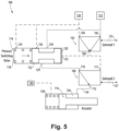
- first solenoid 102 is shown outputting a high pressure from pressure outlet 106.
- first solenoid 102 is shown outputting a low pressure from pressure outlet 106.
- the low pressure output from first solenoid 102 is received at side pressure port 125 and causes the spool 122 of pressure switching valve 114 to move right toward the second side 120 of pressure switching valve 114.
- This translation of the spool 122 causes the additional secondary pressure port 128 to open and thereby exposes the high pressure second pressure source 132 to the first pressure input 110 of the second solenoid 108 via the pressure outlet 129.
- the second solenoid 108 then provides the high-pressure to the actuator control line 134 via a pressure outlet 112.
- the first solenoid 102 is in control when the second solenoid 108 has failed such that second solenoid 108 only passes fluid to the right input, e.g., second pressure input 111.
- the first solenoid 102 can be operated to direct the output at pressure output 112 to either low pressure via first pressure source 130 or high pressure via second pressure source 132.
- the pressure-switching valve 114 does not affect any control of the second solenoid 102.
- first solenoid 102 is shown outputting a high pressure from pressure outlet 106 to the second pressure input 111 of the second solenoid 108.
- the second solenoid 108 then provides the high-pressure to the actuator control line 134 via a pressure outlet 112.
- first solenoid 102 is shown outputting a low pressure from pressure outlet 106.
- the low-pressure output from first solenoid 102 is received at the second pressure input 111 of the second solenoid 108.
- the second solenoid 108 then provides the low-pressure to the actuator control line 134 via a pressure outlet 112
- system 100 provides reduced weight and reduced size envelope as compared with traditional EHSVs. Moreover, if the effector system that the actuator body 140 controls does not have its own means of tracking performance (e.g., via position sensor, pressure sensor, temperature sensor, etc.) embodiments of system 100 can use proximity probes (which have good resolution to determine position in a non-modulated actuator) to determine the left or right position of the actuator body 140. Proximity probes are magnetic sensors that can be installed in the actuator valve 116 to determine position of actuator body 140 (e.g., is the actuator body in the left or right position).
- Proximity probes are lighter than a linear variable differential transformer (LVDT), which would typically be used to detect the position of the actuator in an EHSV system.
- LVDT linear variable differential transformer
- the ability to use these proximity probes results in further potential weight and size reduction as compared with traditional EHSV systems.
- solenoids 102 and 108 have little to no internal leakage, system 100 also provides for improved fuel system efficiency and reliability as compared with EHSVs.
- the simplified control nature of solenoids e.g., the simple I/O control structure, provides easier control as compared with EHSVs. As such, in situations where a non-modulated effector is appropriate, system 100 offers considerable benefits over traditional EHSVs.
- a method for controlling an actuator, e.g. actuator valve 116, with dual redundant solenoids, e.g. first and second solenoids 102 and 108 includes providing a low pressure from a low pressure source, e.g. first pressure source 130, to the first solenoid and providing a high pressure from a high pressure source, e.g. second pressure source 132 to the first solenoid.
- the method includes providing the low pressure from the low-pressure source to a pressure-switching valve, e.g. pressure switching valve 114.
- the method includes providing the high pressure from the high-pressure source to the pressure-switching valve.
- the method includes providing a control pressure from either the first solenoid or the second solenoid.
- the method includes controlling an actuator valve, e.g., actuator valve 116, with an output of the second solenoid.
- the method includes controlling the actuator valve with the output of the second solenoid by providing the high pressure from the first solenoid to a second pressure input, e.g., the second pressure input 111, of the second solenoid and to the pressure-switching valve thereby exposing a first inlet, e.g. a first inlet 110, of the second solenoid to the low pressure source via a pressure outlet, e.g. pressure outlet 129, of the pressure-switching valve.
- the method includes controlling the second solenoid to supply an actuator control cavity, e.g. actuator control cavity 136, with either the high pressure or low pressure via an actuator control line, e.g., the actuator control line 134.
- the method includes controlling the actuator valve with the output of the second solenoid by providing the low pressure from the first solenoid to the second pressure input of the second solenoid and to the pressure-switching valve thereby exposing a first inlet, e.g. a first inlet 110, of the second solenoid to the high pressure source via the pressure outlet of the pressure-switching valve.
- the method includes controlling the second solenoid to supply the actuator control cavity with either the high pressure or low pressure via the actuator control line.
- the method includes controlling the actuator valve with an output of the first solenoid.
- the method includes exposing the first side of the pressure-switching valve to the low-pressure source.
- the low-pressure source provided to the pressure switching valve acts to expose the first inlet of the second solenoid to the high-pressure source via the pressure outlet of the pressure-switching valve and provides a high-pressure source to the actuator control line via a pressure outlet, e.g. pressure outlet 112, of the second solenoid.
- a pressure outlet e.g. pressure outlet 112
- the method includes controlling the actuator valve with an output of the first solenoid by exposing the first side of the pressure-switching valve to the high-pressure source.
- the high-pressure source provided to the pressure-switching valve acts to expose the first inlet of the second solenoid to the low-pressure source via the pressure outlet of the pressure-switching valve, thereby providing a low-pressure source to the actuator control line via the pressure outlet of the second solenoid.
- the method includes controlling the actuator valve with an output of the first solenoid by exposing a second inlet, e.g. a second inlet 111, of the second solenoid to either the high pressure source or low pressure source.
- a second inlet e.g. a second inlet 111
- the method includes controlling the actuator valve with an output of the first solenoid by exposing the second inlet of the second solenoid to the low pressure source and thereby providing a low pressure source to the actuator control line via a pressure outlet of the second solenoid.
- the method includes controlling the actuator valve with an output of the first solenoid by exposing a second inlet of the second solenoid to the low pressure source and thereby providing a low pressure source to the actuator control line via a pressure outlet of the second solenoid.
Landscapes
- Engineering & Computer Science (AREA)
- Mechanical Engineering (AREA)
- General Engineering & Computer Science (AREA)
- Physics & Mathematics (AREA)
- Fluid Mechanics (AREA)
- Chemical & Material Sciences (AREA)
- Analytical Chemistry (AREA)
- Fluid-Pressure Circuits (AREA)
- Magnetically Actuated Valves (AREA)
Abstract
Description
- The present disclosure relates to actuator systems and more particularly to solenoid driven actuator systems.
- In many turbine engines, effector actuation systems (vanes angle, nozzle area, etc) are usually modulated, but sometimes a two-position system may be advantageous. In modern turbine engines, weight and space are more critical than previous engines because of the increased externals content added to improve engine efficiency. A traditional modulating actuator system usually has two Electro-Hydraulic Servo Valves (EHSVs) and a solenoid driven transfer valve, which tend to be heavy.
- The conventional techniques have been considered satisfactory for their intended purpose. However, there is a need for improved actuator systems. This disclosure provides a solution for this need.
- A solenoid driven actuator system includes a first solenoid having at least one pressure input and a pressure outlet downstream from the at least one pressure input. The system includes a second solenoid having at least one pressure input and a pressure outlet downstream from the at least one pressure input. The system includes a pressure-switching valve operatively coupled to the first and second solenoids. The system includes an actuator operatively coupled to the pressure outlet of the second solenoid.
- In accordance with some embodiments, the at least one pressure input of the first solenoid includes a first pressure input and a second pressure input. The at least one pressure input of the second solenoid can include a first pressure input and a second pressure input. The pressure-switching valve can be in fluid communication with the first pressure input of the second solenoid. The pressure outlet of the first solenoid can be in fluid communication with the second pressure input of the second solenoid.
- The pressure-switching valve can include a first side, a second side and a slidable spool therebetween. The first side of the pressure-switching valve can be in fluid communication with a first pressure source through a first side pressure port. The second side of the pressure-switching valve can be in fluid communication with the pressure outlet of the first solenoid through a second side pressure port. The pressure-switching valve can include a secondary pressure port between the first and second sides of the pressure-switching valve. The secondary pressure port can be in fluid communication with a first pressure source. The pressure-switching valve can include an additional secondary pressure port between the first and second sides of the pressure-switching valve. The additional secondary pressure port can be in fluid communication with a second pressure source. At least one of the secondary pressure port or the additional secondary pressure port of the pressure-switching valve can be in fluid communication with a first pressure input of the second solenoid.
- In accordance with another aspect, a method for controlling an actuator valve with a dual redundant solenoids includes providing a low pressure from a low pressure source to a first solenoid and providing a high pressure from a high pressure source to the first solenoid. The high pressure source is at a higher pressure relative to the low pressure source. The method includes providing the low pressure from the low pressure source to a pressure-switching valve. The method includes providing the high pressure from the high pressure source to the pressure-switching valve. The method includes providing a control pressure from at least one of the first solenoid or the pressure-switching valve to a second solenoid. The method includes controlling an actuator valve with an output of the second solenoid.
- In some embodiments, the method includes controlling the actuator valve with the output of the second solenoid when the first solenoid is in a failure mode to the high pressure by providing the high pressure from the first solenoid to the pressure-switching valve thereby exposing a first inlet of the second solenoid to the low pressure source via the pressure-switching valve. The method can include controlling the actuator valve with the output of the second solenoid when the first solenoid is in a failure mode to the low pressure by providing the low pressure from the first solenoid to the pressure-switching valve thereby exposing a first inlet of the second solenoid to the high pressure source via the pressure-switching valve.
- The method can include controlling the actuator valve with an output of the first solenoid when the second solenoid is in a failure mode by exposing a first side of the pressure-switching valve to the high pressure source thereby exposing a first inlet of the second solenoid to the low pressure source. The method can include controlling the actuator valve with an output of the first solenoid when the second solenoid is in a failure mode by exposing a first side of the pressure-switching valve to the low pressure source thereby exposing a first inlet of the second solenoid to the high pressure source.
- These and other features of the systems and methods of the subject disclosure will become more readily apparent to those skilled in the art from the following detailed description of the preferred embodiments taken in conjunction with the drawings.
- So that those skilled in the art to which the subject disclosure appertains will readily understand how to make and use the devices and methods of the subject disclosure without undue experimentation, preferred embodiments thereof will be described in detail herein below with reference to certain figures, wherein:
-
Fig. 1 is a schematic depiction of a solenoid driven actuator system constructed in accordance with an embodiment of the present disclosure, showing the first or second solenoid in control; -
Fig. 2 is a schematic depiction of the system ofFig. 1 , showing the second solenoid in control when the first solenoid has failed to high pressure; -
Fig. 3 is a schematic depiction of the system ofFig. 1 , showing the second solenoid in control when the first solenoid has failed to low pressure; -
Fig. 4 is a schematic depiction of the system ofFig. 1 , showing the first solenoid in control when a right side of the second solenoid has failed; -
Fig. 5 is a schematic depiction of the system ofFig. 1 , showing the first solenoid in control when a right side of the second solenoid has failed; -
Fig. 6 is a schematic depiction of the system ofFig. 1 , showing the first solenoid in control when a left side of the second solenoid has failed; and -
Fig. 7 is a schematic depiction of the system ofFig. 1 , showing the first solenoid in control when a left side of the second solenoid has failed. - Reference will now be made to the drawings wherein like reference numerals identify similar structural features or aspects of the subject disclosure. For purposes of explanation and illustration, and not limitation, a schematic view of an exemplary embodiment of the solenoid driven actuator system in accordance with the disclosure is shown in
Fig. 1 and is designated generally byreference character 100. Other embodiments of the solenoid driven actuator systems in accordance with the disclosure, or aspects thereof, are provided inFigs. 2-7 as will be described. The systems and methods described herein can be used to provide a two-position actuator valve that is lighter weight and smaller in size than traditional modulating actuator systems. - As shown in
Fig. 1 , a solenoid drivenactuator system 100 is a dual-redundant actuator system having two solenoids controlled on the same or different channels.System 100 includes afirst solenoid 102 having afirst pressure input 104 and asecond pressure input 105 and apressure outlet 106 downstream frompressure inputs system 100 includes asecond solenoid 108 having afirst pressure input 110, asecond pressure input 111, and apressure outlet 112 downstream from thepressure inputs system 100 includes a pressure-switchingvalve 114 operatively coupled to the first andsecond solenoids system 100 includes anactuator valve 116 operatively coupled to thepressure outlet 112 of thesecond solenoid 108. Thefirst solenoid 102 controls the pressure going to thesecond solenoid 108 both directly and through thepressure switching valve 114. With a failure of either solenoid, control overactuator valve 116 can be maintained through the working solenoid. - With continued reference to
Fig. 1 , the pressure-switchingvalve 114 is in fluid communication with thefirst pressure input 110 of thesecond solenoid 108 via apressure outlet 129. The pressure-switchingvalve 114 includes afirst side 118, asecond side 120 and aslidable spool 122 therebetween. Thepressure outlet 106 of thefirst solenoid 102 is in fluid communication with thesecond pressure input 111 of thesecond solenoid 108. Thefirst side 118 of the pressure-switchingvalve 114 is in fluid communication with afirst pressure source 130 through a firstside pressure port 124. Thesecond side 120 of the pressure-switchingvalve 114 is in fluid communication with thepressure outlet 106 of thefirst solenoid 102 through a secondside pressure port 125. The pressure-switchingvalve 114 includes asecondary pressure port 126 between the first andsecond sides valve 114. Thesecondary pressure port 126 is in fluid communication with afirst pressure source 130. The pressure-switchingvalve 114 includes an additionalsecondary pressure port 128 between the first and second sides, 118 and 120, respectively, of the pressure-switchingvalve 114. The additionalsecondary pressure port 128 is in fluid communication with asecond pressure source 132. As described in more detail below, depending on the output from thefirst solenoid 102 atpressure outlet 106, either thesecondary pressure port 126 or the additionalsecondary pressure port 128 of the pressure-switchingvalve 114 is in fluid communication with thefirst pressure input 110 of thesecond solenoid 108 viapressure outlet 129. - With continued reference to
Fig. 1 ,system 100 is shown where both first andsecond solenoids first solenoid 102 or thesecond solenoid 108 can control the output toactuator valve 116. In accordance with some embodiments, control offirst solenoid 102 is executed through acommunication channel 155 and control ofsecond solenoid 108 is executed withseparate communication channel 157, e.g., one independent fromcommunication channel 155. Those skilled in the art will readily appreciate that in accordance with some embodiments, first andsecond solenoids Fig. 1 , thesecond solenoid 108 is shown in control.Second solenoid 108 can supply anactuator control cavity 136 with a high pressure (e.g., from second pressure source 132) or a low pressure (e.g. from a first pressure source 130) via anactuator control line 134. Low-pressure is schematically shown with the larger dashed lines and high-pressure is schematically shown with the smaller dashed line throughout the figures. The pressure inactuator control cavity 136 controls whetherspring 138 is compressed or released by controlling the axial position of an actuator body 140. In this state, it is also contemplated that thefirst solenoid 102 may also be used to controlactuator valve 116 through the pressure-switchingvalve 114. Those skilled in the art will readily appreciate that in some embodiments, theactuator valve 116 may be arranged differently (e.g.,spring 138 may positioned within the actuator control cavity 136) or may be a two-position valve. - With reference now to
Fig. 2 , thefirst solenoid 102 is in a failure condition where thefirst solenoid 102 has failed to high-pressure, e.g. thesecond pressure source 132. In this condition, thesecond solenoid 108 can be operated to direct the output atpressure output 112 to either high pressure viasecond pressure source 132 andfirst solenoid 102 or low pressure viafirst pressure source 130 andpressure switching valve 114. This ability stems from the opposite nature of thefirst solenoid 102 and the pressure-switchingvalve 114. Whenfirst solenoid 102 outputs a high pressure frompressure outlet 106, thespool 122 ofpressure switching valve 114 moves left, opening thesecondary pressure port 126 and thereby exposing the low pressure fromfirst pressure source 130 to thefirst pressure input 110 of thesecond solenoid 108 viapressure outlet 129. Thesecond pressure input 111 of thesecond solenoid 108 is supplied high pressure fromsecond pressure source 132 via the failedfirst solenoid 102. As thesecond solenoid 108 is still functional, it is controlled to supplyactuator control cavity 136 with either the high pressure or low pressure viaactuator control line 134. - As shown in
Fig. 3 , thesecond solenoid 108 is in control when thefirst solenoid 102 has failed to low pressure, e.g. thefirst power source 130. In this condition, thesecond solenoid 108 can be operated to direct the output atpressure output 112 to either low pressure viafirst pressure source 130 andfirst solenoid 102 or high pressure viasecond pressure source 132 andpressure switching valve 114. This ability stems from the opposite nature of thefirst solenoid 102 and the pressure-switchingvalve 114. Whenfirst solenoid 102 outputs a low pressure frompressure outlet 106, thespool 122 ofpressure switching valve 114 moves right (e.g., relative to the position inFig. 2 ), opening the additionalsecondary pressure port 128 and thereby exposing the high pressure fromsecond pressure source 132 to thefirst pressure input 110 of thesecond solenoid 108 viapressure outlet 129. Thesecond pressure input 111 of thesecond solenoid 108 is supplied low pressure fromfirst pressure source 130 via the failedfirst solenoid 102. As thesecond solenoid 108 is still functional, it is controlled to supplyactuator control cavity 136 with either the high pressure or low pressure viaactuator control line 134. - As shown in
Figs. 4-5 , thefirst solenoid 102 is in control when thesecond solenoid 108 has failed such that second solenoid only passes fluid to the left input, e.g.,first pressure input 110. In this condition, thefirst solenoid 102 can be operated to direct the output atpressure output 112 to either low pressure viafirst pressure source 130 andpressure switching valve 114 or high pressure viasecond pressure source 132 andpressure switching valve 114. This ability stems from the opposite nature of thefirst solenoid 102 and the pressure-switchingvalve 114. InFig. 4 ,first solenoid 102 is shown outputting a high pressure frompressure outlet 106. The high pressure output fromfirst solenoid 102 is received atside pressure port 125 and causes thespool 122 ofpressure switching valve 114 moves left away fromsecond side 120 ofpressure switching valve 114. This translation of thespool 122 causes thesecondary pressure port 126 to open and thereby exposes the low pressurefirst pressure source 130 to thefirst pressure input 110 of thesecond solenoid 108 viapressure outlet 129. Thesecond solenoid 108 then provides the low-pressure to theactuator control line 134 via apressure outlet 112. InFig. 5 ,first solenoid 102 is shown outputting a low pressure frompressure outlet 106. The low pressure output fromfirst solenoid 102 is received atside pressure port 125 and causes thespool 122 ofpressure switching valve 114 to move right toward thesecond side 120 ofpressure switching valve 114. This translation of thespool 122 causes the additionalsecondary pressure port 128 to open and thereby exposes the high pressuresecond pressure source 132 to thefirst pressure input 110 of thesecond solenoid 108 via thepressure outlet 129. Thesecond solenoid 108 then provides the high-pressure to theactuator control line 134 via apressure outlet 112. - As shown in
Figs. 6-7 , thefirst solenoid 102 is in control when thesecond solenoid 108 has failed such thatsecond solenoid 108 only passes fluid to the right input, e.g.,second pressure input 111. In this condition, thefirst solenoid 102 can be operated to direct the output atpressure output 112 to either low pressure viafirst pressure source 130 or high pressure viasecond pressure source 132. In this condition, the pressure-switchingvalve 114 does not affect any control of thesecond solenoid 102. InFig. 6 ,first solenoid 102 is shown outputting a high pressure frompressure outlet 106 to thesecond pressure input 111 of thesecond solenoid 108. Thesecond solenoid 108 then provides the high-pressure to theactuator control line 134 via apressure outlet 112. InFig. 7 ,first solenoid 102 is shown outputting a low pressure frompressure outlet 106. The low-pressure output fromfirst solenoid 102 is received at thesecond pressure input 111 of thesecond solenoid 108. Thesecond solenoid 108 then provides the low-pressure to theactuator control line 134 via apressure outlet 112 - As
solenoids system 100 provides reduced weight and reduced size envelope as compared with traditional EHSVs. Moreover, if the effector system that the actuator body 140 controls does not have its own means of tracking performance (e.g., via position sensor, pressure sensor, temperature sensor, etc.) embodiments ofsystem 100 can use proximity probes (which have good resolution to determine position in a non-modulated actuator) to determine the left or right position of the actuator body 140. Proximity probes are magnetic sensors that can be installed in theactuator valve 116 to determine position of actuator body 140 (e.g., is the actuator body in the left or right position). Proximity probes are lighter than a linear variable differential transformer (LVDT), which would typically be used to detect the position of the actuator in an EHSV system. The ability to use these proximity probes results in further potential weight and size reduction as compared with traditional EHSV systems. Additionally, becausesolenoids system 100 also provides for improved fuel system efficiency and reliability as compared with EHSVs. The simplified control nature of solenoids, e.g., the simple I/O control structure, provides easier control as compared with EHSVs. As such, in situations where a non-modulated effector is appropriate,system 100 offers considerable benefits over traditional EHSVs. - A method for controlling an actuator,
e.g. actuator valve 116, with dual redundant solenoids, e.g. first andsecond solenoids first pressure source 130, to the first solenoid and providing a high pressure from a high pressure source, e.g.second pressure source 132 to the first solenoid. The method includes providing the low pressure from the low-pressure source to a pressure-switching valve, e.g.pressure switching valve 114. The method includes providing the high pressure from the high-pressure source to the pressure-switching valve. InFig. 1 , where both the first andsecond solenoids actuator valve 116, with an output of the second solenoid. - When the first solenoid is in a failure mode to the high-pressure source, e.g., as shown in
Fig. 2 , the method includes controlling the actuator valve with the output of the second solenoid by providing the high pressure from the first solenoid to a second pressure input, e.g., thesecond pressure input 111, of the second solenoid and to the pressure-switching valve thereby exposing a first inlet, e.g. afirst inlet 110, of the second solenoid to the low pressure source via a pressure outlet,e.g. pressure outlet 129, of the pressure-switching valve. As the second solenoid is still functional, the method includes controlling the second solenoid to supply an actuator control cavity, e.g.actuator control cavity 136, with either the high pressure or low pressure via an actuator control line, e.g., theactuator control line 134. - When the first solenoid is in a failure mode to the low pressure source, e.g., as shown in
Fig. 3 , the method includes controlling the actuator valve with the output of the second solenoid by providing the low pressure from the first solenoid to the second pressure input of the second solenoid and to the pressure-switching valve thereby exposing a first inlet, e.g. afirst inlet 110, of the second solenoid to the high pressure source via the pressure outlet of the pressure-switching valve. As the second solenoid is still functional, the method includes controlling the second solenoid to supply the actuator control cavity with either the high pressure or low pressure via the actuator control line. - When the second solenoid is in a failure mode to its left side, as shown in
Figs. 4-5 , the method includes controlling the actuator valve with an output of the first solenoid. As shown inFig. 4 , if a high-pressure output at the pressure outlet is desired, the method includes exposing the first side of the pressure-switching valve to the low-pressure source. The low-pressure source provided to the pressure switching valve acts to expose the first inlet of the second solenoid to the high-pressure source via the pressure outlet of the pressure-switching valve and provides a high-pressure source to the actuator control line via a pressure outlet,e.g. pressure outlet 112, of the second solenoid. As shown inFig. 5 , if a low-pressure output at the pressure outlet is desired, the method includes controlling the actuator valve with an output of the first solenoid by exposing the first side of the pressure-switching valve to the high-pressure source. The high-pressure source provided to the pressure-switching valve acts to expose the first inlet of the second solenoid to the low-pressure source via the pressure outlet of the pressure-switching valve, thereby providing a low-pressure source to the actuator control line via the pressure outlet of the second solenoid. - When the second solenoid is in a failure mode to its right side, as shown in
Figs. 6-7 , the method includes controlling the actuator valve with an output of the first solenoid by exposing a second inlet, e.g. asecond inlet 111, of the second solenoid to either the high pressure source or low pressure source. As shown inFig. 6 , if a high-pressure output at the pressure outlet is desired, the method includes controlling the actuator valve with an output of the first solenoid by exposing the second inlet of the second solenoid to the low pressure source and thereby providing a low pressure source to the actuator control line via a pressure outlet of the second solenoid. As shown inFig. 7 , if a low pressure output at the pressure outlet of the second solenoid is desired, the method includes controlling the actuator valve with an output of the first solenoid by exposing a second inlet of the second solenoid to the low pressure source and thereby providing a low pressure source to the actuator control line via a pressure outlet of the second solenoid. - The methods and systems of the present disclosure, as described above and shown in the drawings, provide for solenoid driven actuator system, with superior properties including reduced weight and size, and increased reliability and efficiency. The systems and methods of the present invention can apply to a variety of actuators, or the like. While the apparatus and methods of the subject disclosure have been shown and described with reference to preferred embodiments, those skilled in the art will readily appreciate that changes and/or modifications may be made thereto without departing from the scope of the subject disclosure. The scope of the invention is defined by the appended claims.
Claims (15)
- A solenoid driven actuator system, the system comprising:a first solenoid (102) having at least one pressure input (104, 105) and a pressure outlet (106) downstream from the at least one pressure input;a second solenoid (108) having at least one pressure input (110, 111) and a pressure outlet (112) downstream from the at least one pressure input;a pressure-switching valve (114) operatively coupled to the first and second solenoids; andan actuator valve (116) operatively coupled to the pressure outlet of the second solenoid.
- The solenoid driven actuator system of claim 1, wherein the at least one pressure input (104) of the first solenoid (102) includes a first pressure input (104) and a second pressure input (105).
- The solenoid driven actuator system of claim 1 or 2, wherein the at least one pressure input (110) of the second solenoid (108) includes a first pressure input (110) and a second pressure input (111).
- The solenoid driven actuator system of claim 3, wherein the pressure-switching valve (114) is in fluid communication with the first pressure input (110) of the second solenoid (108).
- The solenoid driven actuator system of claim 3 or 4, wherein the pressure outlet (112) of the first solenoid (102) is in fluid communication with the second pressure input (111) of the second solenoid (108).
- The solenoid driven actuator system of any preceding claim, wherein the pressure-switching valve (114) includes a first side (118), a second side (120) and a slidable spool (122) therebetween.
- The solenoid driven actuator system of claim 6, wherein the first side (118) of the pressure-switching valve (114) is in fluid communication with a first pressure source (130) through a first side pressure port (124).
- The solenoid driven actuator system of claim 6 or 7, wherein the second side (120) of the pressure-switching valve (114) is in fluid communication with the pressure outlet (112) of the first solenoid (102) through a second side pressure port (125).
- The solenoid driven actuator system of any of claims 6 to 8, wherein the pressure-switching valve (114) includes a secondary pressure port (126) between the first and second sides (118, 120) of the pressure-switching valve, wherein the secondary pressure port is in fluid communication with a first pressure source (130).
- The solenoid driven actuator system of claim 9, wherein the pressure-switching valve (114) includes an additional secondary pressure port (128) between the first and second sides (118, 120) of the pressure-switching valve, wherein the additional secondary pressure port is in fluid communication with a second pressure source (132).
- The solenoid driven actuator system of claim 10, wherein at least one of the secondary pressure port (126) or the additional secondary pressure port (128) of the pressure-switching valve (114) is in fluid communication with a first pressure input (110) of the second solenoid (108).
- A method for controlling an actuator valve with a dual redundant solenoids, the method comprising:providing a low pressure from a low pressure source to a first solenoid;providing a high pressure from a high pressure source to the first solenoid, wherein the high pressure source is at a higher pressure relative to the low pressure source;providing the low pressure from the low pressure source to a pressure-switching valve;providing the high pressure from the high pressure source to the pressure-switching valve;providing a control pressure from at least one of the first solenoid or the pressure-switching valve to a second solenoid; andcontrolling an actuator valve with an output of the second solenoid.
- The method as recited in claim 12, controlling the actuator valve with the output of the second solenoid when the first solenoid is in a failure mode to the high pressure by providing the high pressure from the first solenoid to the pressure-switching valve thereby exposing a first inlet of the second solenoid to the low pressure source via the pressure-switching valve.
- The method as recited in claim 12 or 13, controlling the actuator valve with the output of the second solenoid when the first solenoid is in a failure mode to the low pressure by providing the low pressure from the first solenoid to the pressure-switching valve thereby exposing a first inlet of the second solenoid to the high pressure source via the pressure-switching valve.
- The method as recited in any of claims 12 to 14, controlling the actuator valve with an output of the first solenoid when the second solenoid is in a failure mode by exposing a first side of the pressure-switching valve to the high pressure source thereby exposing a first inlet of the second solenoid to the low pressure source; and/or controlling the actuator valve with an output of the first solenoid when the second solenoid is in a failure mode by exposing a first side of the pressure-switching valve to the low pressure source thereby exposing a first inlet of the second solenoid to the high pressure source.
Applications Claiming Priority (1)
| Application Number | Priority Date | Filing Date | Title |
|---|---|---|---|
| US17/675,551 US11852172B2 (en) | 2022-02-18 | 2022-02-18 | Solenoid driven actuator systems |
Publications (2)
| Publication Number | Publication Date |
|---|---|
| EP4230845A1 true EP4230845A1 (en) | 2023-08-23 |
| EP4230845B1 EP4230845B1 (en) | 2025-07-16 |
Family
ID=85283613
Family Applications (1)
| Application Number | Title | Priority Date | Filing Date |
|---|---|---|---|
| EP23157118.3A Active EP4230845B1 (en) | 2022-02-18 | 2023-02-16 | Solenoid valve driven actuator systems |
Country Status (2)
| Country | Link |
|---|---|
| US (1) | US11852172B2 (en) |
| EP (1) | EP4230845B1 (en) |
Families Citing this family (2)
| Publication number | Priority date | Publication date | Assignee | Title |
|---|---|---|---|---|
| US20250044816A1 (en) * | 2023-07-31 | 2025-02-06 | Hamilton Sundstrand Corporation | Valve systems |
| US12163537B1 (en) * | 2023-10-20 | 2024-12-10 | Hamilton Sundstrand Corporation | Three way transfer valve for parallel electrohydraulic servo valve control of actuator |
Citations (3)
| Publication number | Priority date | Publication date | Assignee | Title |
|---|---|---|---|---|
| US10577080B2 (en) * | 2017-08-23 | 2020-03-03 | Hamilton Sundstrand Corporation | Dual valve systems for actuator control |
| DE102019128921A1 (en) * | 2018-10-25 | 2020-04-30 | Svm Schultz Verwaltungs-Gmbh & Co. Kg | Valve arrangement and method for throttling an actuator |
| US20210095699A1 (en) * | 2019-09-27 | 2021-04-01 | ASCO Numatics (India) Private Limited | Manifold system for fluid delivery |
Family Cites Families (18)
| Publication number | Priority date | Publication date | Assignee | Title |
|---|---|---|---|---|
| CH666132A5 (en) * | 1984-07-20 | 1988-06-30 | Bbc Brown Boveri & Cie | DEVICE FOR MONITORING PHYSICAL QUANTITIES IN PLANTS. |
| US4783107A (en) * | 1985-06-04 | 1988-11-08 | Clemson University | Method and apparatus for controlling impact force during rapid robotic acquisition of object |
| JP2972530B2 (en) * | 1994-11-16 | 1999-11-08 | 新キャタピラー三菱株式会社 | Work machine control device for construction machinery |
| US6478048B2 (en) * | 1999-01-19 | 2002-11-12 | Triconex, Incorporated | Two out of three voting solenoid arrangement |
| US6722383B2 (en) * | 2001-01-09 | 2004-04-20 | Angela Summers | Variable function voting solenoid-operated valve apparatus and testing method therefor |
| US6755214B2 (en) * | 2001-08-03 | 2004-06-29 | Ross Operating Value Company | Solenoid valve for reduced energy consumption |
| JP5545511B2 (en) * | 2012-05-23 | 2014-07-09 | 横河電機株式会社 | Valve remote control device |
| US9274176B2 (en) | 2012-07-20 | 2016-03-01 | Pratt & Whitney Canada Corp. | Solenoid transient variable resistance feedback for effecter position detection |
| JP6160592B2 (en) * | 2013-11-19 | 2017-07-12 | トヨタ自動車株式会社 | Hydraulic control circuit of power transmission device |
| DE102016116516A1 (en) * | 2016-09-05 | 2018-03-08 | Knorr-Bremse Systeme für Nutzfahrzeuge GmbH | A solenoid valve device for a brake system for a vehicle, brake system for a vehicle and method for mounting a solenoid valve device for a brake system for a vehicle |
| DK3529130T3 (en) * | 2016-10-18 | 2023-06-19 | Parker Hannifin Emea Sarl | Electro-hydraulic control system with failsafe pilot valves |
| US10222239B2 (en) | 2017-04-14 | 2019-03-05 | Hamilton Sundstrand Corporation | Position detection systems and methods |
| US10704411B2 (en) | 2018-08-03 | 2020-07-07 | General Electric Company | Variable vane actuation system for a turbo machine |
| EP3693616A1 (en) * | 2019-02-11 | 2020-08-12 | Goodrich Actuation Systems SAS | Actuator control valve arrangement |
| US11215067B2 (en) * | 2019-02-26 | 2022-01-04 | Hamilton Sundstrand Corporation | Dual redundant two-stage valve |
| US11415154B2 (en) * | 2019-04-12 | 2022-08-16 | Husco International, Inc. | Hydraulic systems and methods for nested pressure regulating valves |
| EP3750797B1 (en) * | 2019-06-14 | 2025-03-26 | Goodrich Actuation Systems SAS | Spoiler droop function with mechanical feedback driving hydraulic valve |
| EP3767112B1 (en) * | 2019-07-19 | 2024-09-18 | Goodrich Actuation Systems SAS | Actuator control arrangement |
-
2022
- 2022-02-18 US US17/675,551 patent/US11852172B2/en active Active
-
2023
- 2023-02-16 EP EP23157118.3A patent/EP4230845B1/en active Active
Patent Citations (3)
| Publication number | Priority date | Publication date | Assignee | Title |
|---|---|---|---|---|
| US10577080B2 (en) * | 2017-08-23 | 2020-03-03 | Hamilton Sundstrand Corporation | Dual valve systems for actuator control |
| DE102019128921A1 (en) * | 2018-10-25 | 2020-04-30 | Svm Schultz Verwaltungs-Gmbh & Co. Kg | Valve arrangement and method for throttling an actuator |
| US20210095699A1 (en) * | 2019-09-27 | 2021-04-01 | ASCO Numatics (India) Private Limited | Manifold system for fluid delivery |
Also Published As
| Publication number | Publication date |
|---|---|
| EP4230845B1 (en) | 2025-07-16 |
| US11852172B2 (en) | 2023-12-26 |
| US20230265867A1 (en) | 2023-08-24 |
Similar Documents
| Publication | Publication Date | Title |
|---|---|---|
| EP4230877B1 (en) | Solenoid valve driven actuator systems | |
| EP4230845B1 (en) | Solenoid valve driven actuator systems | |
| US6796526B2 (en) | Augmenting flight control surface actuation system and method | |
| EP1565373B1 (en) | Augmenting flight control surface actuation system and method | |
| EP4166794A1 (en) | Directional control valve with hydraulic pilot control | |
| JPS628612B2 (en) | ||
| US20030140625A1 (en) | Pressure switching valve for multiple redundant electrohydraulic servo valve systems | |
| JP2001504927A (en) | Zero drift actuator fixed in case of failure | |
| EP3623583A1 (en) | System for adjusting a variable position vane in an aircraft engine | |
| EP4215735B1 (en) | Fuel systems | |
| US11473598B2 (en) | Failsafe electro-hydraulic servo valve | |
| US4145876A (en) | Jet engine fuel flow transfer valve | |
| EP4542058A1 (en) | Three way transfer valve for parallel electrohydraulic servo valve control of actuator | |
| EP4283111B1 (en) | Dual valve fuel metering systems | |
| CN219432208U (en) | Redundant quick-closing proportional valve control hydraulic servo system | |
| US5501245A (en) | Coaxial pressurized fluid flow regulator | |
| JP2000170935A (en) | Multi-function fluid control valve | |
| US11391301B2 (en) | Electrohydraulic poppet valve device control that maintains the last commanded position of a device upon power interruption and provides back-up position control | |
| US11384850B2 (en) | Hydraulic control valves for ram air turbine stow actuators | |
| EP2834480B1 (en) | Hydraulic actuator and gas exchange valve arrangement | |
| US6955113B2 (en) | Electro-hydraulic actuator with mechanical servo position feedback | |
| CN112032118A (en) | A governor control system for preventing oil spillage | |
| US12398720B2 (en) | Direct controlled variable displacement valves with dual set point pressure relief | |
| US20250129807A1 (en) | Parallel electrohydraulic servo valve controlled actuator with failure accommodation | |
| EP2834481B1 (en) | Hydraulic actuator |
Legal Events
| Date | Code | Title | Description |
|---|---|---|---|
| PUAI | Public reference made under article 153(3) epc to a published international application that has entered the european phase |
Free format text: ORIGINAL CODE: 0009012 |
|
| STAA | Information on the status of an ep patent application or granted ep patent |
Free format text: STATUS: THE APPLICATION HAS BEEN PUBLISHED |
|
| AK | Designated contracting states |
Kind code of ref document: A1 Designated state(s): AL AT BE BG CH CY CZ DE DK EE ES FI FR GB GR HR HU IE IS IT LI LT LU LV MC ME MK MT NL NO PL PT RO RS SE SI SK SM TR |
|
| STAA | Information on the status of an ep patent application or granted ep patent |
Free format text: STATUS: REQUEST FOR EXAMINATION WAS MADE |
|
| 17P | Request for examination filed |
Effective date: 20240222 |
|
| RBV | Designated contracting states (corrected) |
Designated state(s): AL AT BE BG CH CY CZ DE DK EE ES FI FR GB GR HR HU IE IS IT LI LT LU LV MC ME MK MT NL NO PL PT RO RS SE SI SK SM TR |
|
| STAA | Information on the status of an ep patent application or granted ep patent |
Free format text: STATUS: EXAMINATION IS IN PROGRESS |
|
| 17Q | First examination report despatched |
Effective date: 20240717 |
|
| GRAP | Despatch of communication of intention to grant a patent |
Free format text: ORIGINAL CODE: EPIDOSNIGR1 |
|
| STAA | Information on the status of an ep patent application or granted ep patent |
Free format text: STATUS: GRANT OF PATENT IS INTENDED |
|
| INTG | Intention to grant announced |
Effective date: 20250305 |
|
| GRAS | Grant fee paid |
Free format text: ORIGINAL CODE: EPIDOSNIGR3 |
|
| GRAA | (expected) grant |
Free format text: ORIGINAL CODE: 0009210 |
|
| STAA | Information on the status of an ep patent application or granted ep patent |
Free format text: STATUS: THE PATENT HAS BEEN GRANTED |
|
| AK | Designated contracting states |
Kind code of ref document: B1 Designated state(s): AL AT BE BG CH CY CZ DE DK EE ES FI FR GB GR HR HU IE IS IT LI LT LU LV MC ME MK MT NL NO PL PT RO RS SE SI SK SM TR |
|
| REG | Reference to a national code |
Ref country code: GB Ref legal event code: FG4D |
|
| REG | Reference to a national code |
Ref country code: CH Ref legal event code: EP |
|
| REG | Reference to a national code |
Ref country code: DE Ref legal event code: R096 Ref document number: 602023004756 Country of ref document: DE |
|
| REG | Reference to a national code |
Ref country code: IE Ref legal event code: FG4D |
|
| REG | Reference to a national code |
Ref country code: NL Ref legal event code: MP Effective date: 20250716 |
|
| PG25 | Lapsed in a contracting state [announced via postgrant information from national office to epo] |
Ref country code: PT Free format text: LAPSE BECAUSE OF FAILURE TO SUBMIT A TRANSLATION OF THE DESCRIPTION OR TO PAY THE FEE WITHIN THE PRESCRIBED TIME-LIMIT Effective date: 20251117 |
|
| PG25 | Lapsed in a contracting state [announced via postgrant information from national office to epo] |
Ref country code: NL Free format text: LAPSE BECAUSE OF FAILURE TO SUBMIT A TRANSLATION OF THE DESCRIPTION OR TO PAY THE FEE WITHIN THE PRESCRIBED TIME-LIMIT Effective date: 20250716 |
|
| REG | Reference to a national code |
Ref country code: AT Ref legal event code: MK05 Ref document number: 1814221 Country of ref document: AT Kind code of ref document: T Effective date: 20250716 |
|
| PG25 | Lapsed in a contracting state [announced via postgrant information from national office to epo] |
Ref country code: IS Free format text: LAPSE BECAUSE OF FAILURE TO SUBMIT A TRANSLATION OF THE DESCRIPTION OR TO PAY THE FEE WITHIN THE PRESCRIBED TIME-LIMIT Effective date: 20251116 |
|
| PG25 | Lapsed in a contracting state [announced via postgrant information from national office to epo] |
Ref country code: NO Free format text: LAPSE BECAUSE OF FAILURE TO SUBMIT A TRANSLATION OF THE DESCRIPTION OR TO PAY THE FEE WITHIN THE PRESCRIBED TIME-LIMIT Effective date: 20251016 |
|
| REG | Reference to a national code |
Ref country code: LT Ref legal event code: MG9D |
|
| PG25 | Lapsed in a contracting state [announced via postgrant information from national office to epo] |
Ref country code: AT Free format text: LAPSE BECAUSE OF FAILURE TO SUBMIT A TRANSLATION OF THE DESCRIPTION OR TO PAY THE FEE WITHIN THE PRESCRIBED TIME-LIMIT Effective date: 20250716 |
|
| PG25 | Lapsed in a contracting state [announced via postgrant information from national office to epo] |
Ref country code: FI Free format text: LAPSE BECAUSE OF FAILURE TO SUBMIT A TRANSLATION OF THE DESCRIPTION OR TO PAY THE FEE WITHIN THE PRESCRIBED TIME-LIMIT Effective date: 20250716 |
|
| PG25 | Lapsed in a contracting state [announced via postgrant information from national office to epo] |
Ref country code: HR Free format text: LAPSE BECAUSE OF FAILURE TO SUBMIT A TRANSLATION OF THE DESCRIPTION OR TO PAY THE FEE WITHIN THE PRESCRIBED TIME-LIMIT Effective date: 20250716 |
|
| PG25 | Lapsed in a contracting state [announced via postgrant information from national office to epo] |
Ref country code: GR Free format text: LAPSE BECAUSE OF FAILURE TO SUBMIT A TRANSLATION OF THE DESCRIPTION OR TO PAY THE FEE WITHIN THE PRESCRIBED TIME-LIMIT Effective date: 20251017 |
|
| PG25 | Lapsed in a contracting state [announced via postgrant information from national office to epo] |
Ref country code: SE Free format text: LAPSE BECAUSE OF FAILURE TO SUBMIT A TRANSLATION OF THE DESCRIPTION OR TO PAY THE FEE WITHIN THE PRESCRIBED TIME-LIMIT Effective date: 20250716 |
|
| PG25 | Lapsed in a contracting state [announced via postgrant information from national office to epo] |
Ref country code: LV Free format text: LAPSE BECAUSE OF FAILURE TO SUBMIT A TRANSLATION OF THE DESCRIPTION OR TO PAY THE FEE WITHIN THE PRESCRIBED TIME-LIMIT Effective date: 20250716 |
|
| PG25 | Lapsed in a contracting state [announced via postgrant information from national office to epo] |
Ref country code: BG Free format text: LAPSE BECAUSE OF FAILURE TO SUBMIT A TRANSLATION OF THE DESCRIPTION OR TO PAY THE FEE WITHIN THE PRESCRIBED TIME-LIMIT Effective date: 20250716 Ref country code: PL Free format text: LAPSE BECAUSE OF FAILURE TO SUBMIT A TRANSLATION OF THE DESCRIPTION OR TO PAY THE FEE WITHIN THE PRESCRIBED TIME-LIMIT Effective date: 20250716 |
|
| PG25 | Lapsed in a contracting state [announced via postgrant information from national office to epo] |
Ref country code: RS Free format text: LAPSE BECAUSE OF FAILURE TO SUBMIT A TRANSLATION OF THE DESCRIPTION OR TO PAY THE FEE WITHIN THE PRESCRIBED TIME-LIMIT Effective date: 20251016 |
|
| PG25 | Lapsed in a contracting state [announced via postgrant information from national office to epo] |
Ref country code: ES Free format text: LAPSE BECAUSE OF FAILURE TO SUBMIT A TRANSLATION OF THE DESCRIPTION OR TO PAY THE FEE WITHIN THE PRESCRIBED TIME-LIMIT Effective date: 20250716 |
|
| PG25 | Lapsed in a contracting state [announced via postgrant information from national office to epo] |
Ref country code: SM Free format text: LAPSE BECAUSE OF FAILURE TO SUBMIT A TRANSLATION OF THE DESCRIPTION OR TO PAY THE FEE WITHIN THE PRESCRIBED TIME-LIMIT Effective date: 20250716 |
|
| PG25 | Lapsed in a contracting state [announced via postgrant information from national office to epo] |
Ref country code: DK Free format text: LAPSE BECAUSE OF FAILURE TO SUBMIT A TRANSLATION OF THE DESCRIPTION OR TO PAY THE FEE WITHIN THE PRESCRIBED TIME-LIMIT Effective date: 20250716 |
|
| PGFP | Annual fee paid to national office [announced via postgrant information from national office to epo] |
Ref country code: DE Payment date: 20260121 Year of fee payment: 4 |
|
| PG25 | Lapsed in a contracting state [announced via postgrant information from national office to epo] |
Ref country code: IT Free format text: LAPSE BECAUSE OF FAILURE TO SUBMIT A TRANSLATION OF THE DESCRIPTION OR TO PAY THE FEE WITHIN THE PRESCRIBED TIME-LIMIT Effective date: 20250716 |
|
| PG25 | Lapsed in a contracting state [announced via postgrant information from national office to epo] |
Ref country code: CZ Free format text: LAPSE BECAUSE OF FAILURE TO SUBMIT A TRANSLATION OF THE DESCRIPTION OR TO PAY THE FEE WITHIN THE PRESCRIBED TIME-LIMIT Effective date: 20250716 |
|
| PG25 | Lapsed in a contracting state [announced via postgrant information from national office to epo] |
Ref country code: SK Free format text: LAPSE BECAUSE OF FAILURE TO SUBMIT A TRANSLATION OF THE DESCRIPTION OR TO PAY THE FEE WITHIN THE PRESCRIBED TIME-LIMIT Effective date: 20250716 Ref country code: EE Free format text: LAPSE BECAUSE OF FAILURE TO SUBMIT A TRANSLATION OF THE DESCRIPTION OR TO PAY THE FEE WITHIN THE PRESCRIBED TIME-LIMIT Effective date: 20250716 |