EP4230841A1 - Compressor-turbine rotating assembly with integral cooling circuit(s) - Google Patents
Compressor-turbine rotating assembly with integral cooling circuit(s) Download PDFInfo
- Publication number
- EP4230841A1 EP4230841A1 EP23157388.2A EP23157388A EP4230841A1 EP 4230841 A1 EP4230841 A1 EP 4230841A1 EP 23157388 A EP23157388 A EP 23157388A EP 4230841 A1 EP4230841 A1 EP 4230841A1
- Authority
- EP
- European Patent Office
- Prior art keywords
- inlet
- turbine
- rotor
- compressor
- cooling circuit
- Prior art date
- Legal status (The legal status is an assumption and is not a legal conclusion. Google has not performed a legal analysis and makes no representation as to the accuracy of the status listed.)
- Granted
Links
Images




Classifications
-
- F—MECHANICAL ENGINEERING; LIGHTING; HEATING; WEAPONS; BLASTING
- F01—MACHINES OR ENGINES IN GENERAL; ENGINE PLANTS IN GENERAL; STEAM ENGINES
- F01D—NON-POSITIVE DISPLACEMENT MACHINES OR ENGINES, e.g. STEAM TURBINES
- F01D5/00—Blades; Blade-carrying members; Heating, heat-insulating, cooling or antivibration means on the blades or the members
- F01D5/12—Blades
- F01D5/14—Form or construction
- F01D5/18—Hollow blades, i.e. blades with cooling or heating channels or cavities; Heating, heat-insulating or cooling means on blades
-
- F—MECHANICAL ENGINEERING; LIGHTING; HEATING; WEAPONS; BLASTING
- F01—MACHINES OR ENGINES IN GENERAL; ENGINE PLANTS IN GENERAL; STEAM ENGINES
- F01D—NON-POSITIVE DISPLACEMENT MACHINES OR ENGINES, e.g. STEAM TURBINES
- F01D5/00—Blades; Blade-carrying members; Heating, heat-insulating, cooling or antivibration means on the blades or the members
- F01D5/02—Blade-carrying members, e.g. rotors
- F01D5/08—Heating, heat-insulating or cooling means
- F01D5/085—Heating, heat-insulating or cooling means cooling fluid circulating inside the rotor
-
- F—MECHANICAL ENGINEERING; LIGHTING; HEATING; WEAPONS; BLASTING
- F01—MACHINES OR ENGINES IN GENERAL; ENGINE PLANTS IN GENERAL; STEAM ENGINES
- F01D—NON-POSITIVE DISPLACEMENT MACHINES OR ENGINES, e.g. STEAM TURBINES
- F01D25/00—Component parts, details, or accessories, not provided for in, or of interest apart from, other groups
- F01D25/08—Cooling; Heating; Heat-insulation
- F01D25/12—Cooling
-
- F—MECHANICAL ENGINEERING; LIGHTING; HEATING; WEAPONS; BLASTING
- F01—MACHINES OR ENGINES IN GENERAL; ENGINE PLANTS IN GENERAL; STEAM ENGINES
- F01D—NON-POSITIVE DISPLACEMENT MACHINES OR ENGINES, e.g. STEAM TURBINES
- F01D5/00—Blades; Blade-carrying members; Heating, heat-insulating, cooling or antivibration means on the blades or the members
- F01D5/02—Blade-carrying members, e.g. rotors
- F01D5/021—Blade-carrying members, e.g. rotors for flow machines or engines with only one axial stage
-
- F—MECHANICAL ENGINEERING; LIGHTING; HEATING; WEAPONS; BLASTING
- F01—MACHINES OR ENGINES IN GENERAL; ENGINE PLANTS IN GENERAL; STEAM ENGINES
- F01D—NON-POSITIVE DISPLACEMENT MACHINES OR ENGINES, e.g. STEAM TURBINES
- F01D5/00—Blades; Blade-carrying members; Heating, heat-insulating, cooling or antivibration means on the blades or the members
- F01D5/02—Blade-carrying members, e.g. rotors
- F01D5/04—Blade-carrying members, e.g. rotors for radial-flow machines or engines
- F01D5/043—Blade-carrying members, e.g. rotors for radial-flow machines or engines of the axial inlet- radial outlet, or vice versa, type
-
- F—MECHANICAL ENGINEERING; LIGHTING; HEATING; WEAPONS; BLASTING
- F01—MACHINES OR ENGINES IN GENERAL; ENGINE PLANTS IN GENERAL; STEAM ENGINES
- F01D—NON-POSITIVE DISPLACEMENT MACHINES OR ENGINES, e.g. STEAM TURBINES
- F01D5/00—Blades; Blade-carrying members; Heating, heat-insulating, cooling or antivibration means on the blades or the members
- F01D5/34—Rotor-blade aggregates of unitary construction, e.g. formed of sheet laminae
-
- F—MECHANICAL ENGINEERING; LIGHTING; HEATING; WEAPONS; BLASTING
- F02—COMBUSTION ENGINES; HOT-GAS OR COMBUSTION-PRODUCT ENGINE PLANTS
- F02C—GAS-TURBINE PLANTS; AIR INTAKES FOR JET-PROPULSION PLANTS; CONTROLLING FUEL SUPPLY IN AIR-BREATHING JET-PROPULSION PLANTS
- F02C7/00—Features, components parts, details or accessories, not provided for in, or of interest apart form groups F02C1/00 - F02C6/00; Air intakes for jet-propulsion plants
- F02C7/12—Cooling of plants
-
- F—MECHANICAL ENGINEERING; LIGHTING; HEATING; WEAPONS; BLASTING
- F05—INDEXING SCHEMES RELATING TO ENGINES OR PUMPS IN VARIOUS SUBCLASSES OF CLASSES F01-F04
- F05D—INDEXING SCHEME FOR ASPECTS RELATING TO NON-POSITIVE-DISPLACEMENT MACHINES OR ENGINES, GAS-TURBINES OR JET-PROPULSION PLANTS
- F05D2220/00—Application
- F05D2220/30—Application in turbines
- F05D2220/32—Application in turbines in gas turbines
-
- F—MECHANICAL ENGINEERING; LIGHTING; HEATING; WEAPONS; BLASTING
- F05—INDEXING SCHEMES RELATING TO ENGINES OR PUMPS IN VARIOUS SUBCLASSES OF CLASSES F01-F04
- F05D—INDEXING SCHEME FOR ASPECTS RELATING TO NON-POSITIVE-DISPLACEMENT MACHINES OR ENGINES, GAS-TURBINES OR JET-PROPULSION PLANTS
- F05D2260/00—Function
- F05D2260/20—Heat transfer, e.g. cooling
-
- Y—GENERAL TAGGING OF NEW TECHNOLOGICAL DEVELOPMENTS; GENERAL TAGGING OF CROSS-SECTIONAL TECHNOLOGIES SPANNING OVER SEVERAL SECTIONS OF THE IPC; TECHNICAL SUBJECTS COVERED BY FORMER USPC CROSS-REFERENCE ART COLLECTIONS [XRACs] AND DIGESTS
- Y02—TECHNOLOGIES OR APPLICATIONS FOR MITIGATION OR ADAPTATION AGAINST CLIMATE CHANGE
- Y02T—CLIMATE CHANGE MITIGATION TECHNOLOGIES RELATED TO TRANSPORTATION
- Y02T50/00—Aeronautics or air transport
- Y02T50/60—Efficient propulsion technologies, e.g. for aircraft
Definitions
- This disclosure relates generally to a gas turbine engine and, more particularly, to cooling a turbine rotor within the gas turbine engine.
- a gas turbine engine includes a compressor section, a combustor section and a turbine section.
- Some gas turbine engines may be configured with an axial flow turbine rotor, where combustion product flow generally axially through the turbine section.
- Other typically smaller gas turbine engines may be configured with a radial flow turbine rotor, where combustion products flow radially into the turbine section, are turned by the radial flow turbine rotor, and flow generally axially out of the turbine section.
- known radial flow turbine rotors have various advantages, there is still room in the art for improvement. There is a need in the art, for example, for a relatively small radial flow turbine rotor which can withstand relatively high turbine section temperatures and/or exposure to prolonged elevated turbine section temperatures.
- an assembly for a gas turbine engine.
- This assembly includes a compressor rotor, a turbine rotor and a cooling circuit.
- the compressor rotor includes a gas path surface.
- the turbine rotor is rotatable with the compressor rotor about a rotational axis.
- the cooling circuit includes an inlet in the gas path surface. The cooling circuit extends from the inlet, through the compressor rotor and into the turbine rotor.
- this assembly includes a monolithic body rotatable about a rotational axis.
- the monolithic body includes a compressor rotor, a turbine rotor and a cooling circuit.
- the compressor rotor includes a compressor hub and a plurality of compressor blades arranged circumferentially about and connected to the compressor hub.
- the turbine rotor includes a turbine hub and a plurality of turbine blades arranged circumferentially about and connected to the turbine hub.
- the cooling circuit extends within the monolithic body from an inlet in the compressor rotor to an outlet in the turbine rotor.
- this assembly includes a compressor rotor and a turbine rotor.
- the compressor rotor includes a compressor hub and a plurality of compressor blades arranged circumferentially about and connected to the compressor hub.
- the turbine rotor is rotatable with the compressor rotor.
- the turbine rotor includes a turbine hub and a plurality of turbine blades arranged circumferentially about and connected to the turbine hub.
- the cooling circuit includes an inlet and an outlet. The cooling circuit extends from the inlet, through the compressor hub and the turbine hub, to the outlet.
- the assembly may also include a shaft connected to and extending axially between the compressor rotor and the turbine rotor.
- the cooling circuit may extend through the shaft from the compressor rotor to the turbine rotor.
- the compressor rotor may be configured as a radial flow compressor rotor.
- the turbine rotor may also or alternatively be configured as a radial flow turbine rotor.
- At least or only the compressor rotor and the turbine rotor may be formed together as a monolithic body.
- the compressor rotor may include a hub and a plurality of blades.
- the hub may include the gas path surface.
- the blades may be arranged circumferentially about the hub. The blades may project out from the gas path surface.
- the turbine rotor may include a turbine rotor surface.
- the cooling circuit may also include an outlet in the turbine rotor surface. The cooling circuit may extend through the turbine rotor to the outlet fluidly coupling the inlet to the outlet.
- the turbine rotor surface may be or otherwise include a turbine gas path surface.
- the turbine rotor may include a hub and a plurality of blades.
- the blades may be arranged circumferentially about the hub.
- the blades may project out from the turbine rotor surface.
- the turbine rotor surface may form a peripheral boundary of a bore in the turbine rotor.
- the cooling circuit may at least or only include the inlet, the outlet and a passage extending from the inlet to the outlet.
- the cooling circuit may also include a second inlet in the compressor rotor.
- the cooling circuit may extend from the second inlet, through the compressor rotor and into the turbine rotor fluidly coupling the second inlet to the outlet.
- the second inlet may be in the gas path surface.
- the second inlet may be axially spaced from the inlet along the rotational axis.
- the second inlet may be circumferentially spaced from the inlet about the rotational axis.
- the cooling circuit may include a first capillary, a second capillary and an artery.
- the first capillary may extend from the inlet to the artery.
- the second capillary may extend from the second inlet to the artery.
- the artery may extend to the outlet.
- the first capillary may be or otherwise include a helical capillary.
- the second capillary may also or alternatively be or otherwise include a helical capillary.
- the artery may still also or alternatively be or otherwise include a helical artery.
- At least a portion of the cooling circuit may spiral about the rotational axis as the cooling circuit extends from the inlet to the outlet.
- the assembly may also include a second cooling circuit.
- the second cooling circuit may include a second inlet in the gas path surface.
- the second cooling circuit may extend from the second inlet, through the compressor rotor and into the turbine rotor.
- the present disclosure may include any one or more of the individual features disclosed above and/or below alone or in any combination thereof.
- FIG. 1 is a partial, sectional schematic illustration of a gas turbine engine 20.
- This gas turbine engine 20 of FIG. 1 is a single spool, radial flow gas turbine engine.
- the gas turbine engine 20 may be configured as an auxiliary power unit (APU), a supplemental power unit (SPU) or a primary power unit (PPU) for generating shaft power, electrical power, bleed flow, or other uses for an aircraft.
- the gas turbine engine 20 may alternatively be configured as a turbojet gas turbine engine, a turboshaft gas turbine engine, a turboprop gas turbine engine or any other type of gas turbine engine that generates thrust for propelling the aircraft during flight.
- the present disclosure is not limited to such an exemplary gas turbine engine nor to aircraft propulsion system applications.
- the gas turbine engine 20 may alternatively include more than one spool and/or be configured in a land based gas turbine engine configured for electrical power generation, an air power generation unit for air mobility, a hybrid power architecture unit, etc.
- the gas turbine engine 20 of FIG. 1 extends axially along an axial centerline 22 between a forward, upstream airflow inlet 24 and an aft, downstream airflow exhaust 26.
- This axial centerline 22 may also be a rotational axis for various components within the gas turbine engine 20.
- the gas turbine engine 20 includes a compressor section 28, a combustor section 30 and a turbine section 32.
- the gas turbine engine 20 also includes a static engine structure 34.
- This static engine structure 34 houses the compressor section 28, the combustor section 30 and the turbine section 32.
- the static engine structure 34 of FIG. 1 also forms the airflow inlet 24 and the airflow exhaust 26.
- the engine sections 28, 30 and 32 are arranged sequentially along a (e.g., annular) core flowpath 36 as the core flowpath 36 extends through the gas turbine engine 20 from the airflow inlet 24 to the airflow exhaust 26.
- the compressor section 28 and the turbine section 32 each include a respective rotor 38, 40.
- the compressor rotor 38 may be configured as a radial flow compressor rotor, which may also be referred to as a radial outflow compressor rotor.
- the compressor rotor 38 of FIG. 1 for example, is configured to receive an axial inflow and provide a radial outflow.
- the compressor rotor 38 of FIG. 1 thereby turns an axial flow radially outward.
- the turbine rotor 40 may be configured as a radial flow turbine rotor, which may also be referred to as a radial inflow turbine rotor.
- the turbine rotor 40 of FIG. 1 is configured to receive a radial inflow and provide an axial outflow.
- the turbine rotor 40 of FIG. 1 thereby turns a radial flow axially aft.
- the compressor rotor 38 is connected to the turbine rotor 40 through an engine shaft 42.
- This shaft 42 is rotatably supported by the static engine structure 34 through a plurality of bearings 44; e.g., rolling element bearings, thrust bearings, journal bearings, etc.
- the combustor section 30 includes a (e.g., annular) combustor 46 with a (e.g., annular) combustion chamber 48.
- the combustor 46 may be configured as a reverse flow combustor. Inlets ports into the combustion chamber 48, for example, may be arranged at (e.g., on, adjacent or proximate) and/or towards an aft end 50 of the combustor 46.
- An outlet 52 from the combustor 46 may be arranged axially aft of an inlet 54 to the turbine section 32.
- the combustor 46 may also be arranged radially outboard of and/or axially overlap at least a (e.g., aft) portion of the turbine section 32.
- the core flowpath 36 of FIG. 1 reverses its directions (e.g., from a forward-to-aft direction to an aft-to-forward direction) a first time as the core flowpath 36 extends into the combustion chamber 48.
- the core flowpath 36 of FIG. 1 then reverses its direction (e.g., from the aft-to-forward direction to the forward-to-aft direction) a second time as the core flowpath 36 extends from the combustion chamber 48 into the turbine section 32.
- the present disclosure is not limited to the foregoing exemplary combustor section arrangement.
- the air within the core flowpath 36 may be referred to as core air.
- This core air is compressed by the compressor rotor 38 and directed into the combustion chamber 48.
- Fuel is injected via one or more fuel injectors (not shown) and mixed with the compressed core air to provide a fuel-air mixture.
- This fuel-air mixture is ignited within the combustion chamber 48 via an igniter (not shown), and combustion products thereof flow through the turbine section 32 and cause the turbine rotor 40 to rotate.
- This rotation of the turbine rotor 40 drives rotation of the compressor rotor 38 and, thus, compression of the air received from the airflow inlet 24.
- An exhaust section 56 of the gas turbine engine 20 receives the combustion products from the turbine section 32. This exhaust section 56 directs the received combustion products out of the gas turbine engine 20 through the airflow exhaust 26.
- Cycle performance of the gas turbine engine 20 may be tied to temperature within the turbine section 32.
- increasing the turbine section 32 temperature may facilitate increasing gas turbine engine efficiency and/or power generation.
- typical turbine rotor materials may degrade when subject to relatively high turbine section temperatures.
- a compressor-turbine rotating assembly 58 e.g., a spool of the present disclosure therefore is configured with internal cooling to facilitate provision of higher turbine section temperatures and/or operation at elevated turbine section temperatures for longer durations.
- the rotating assembly 58 includes the compressor rotor 38, the turbine rotor 40 and the shaft 42. This rotating assembly 58 also includes one or more internal cooling circuits 60 configured to provide the internal cooling to the turbine rotor 40.
- the compressor rotor 38 includes a compressor hub 62 and a plurality of compressor blades 64; e.g., compressor vanes.
- the compressor hub 62 of FIG. 2 extends radially between and to an inner surface 66 (e.g., bore surface) of the compressor hub 62 and a gas path surface 68 of the compressor hub 62.
- the compressor inner surface 66 may form an outer peripheral boundary of an internal bore 70 within the compressor rotor 38, which internal compressor bore 70 of FIG. 2 extends axially through the compressor rotor 38.
- the compressor gas path surface 68 may form a (e.g., radial and/or axial) peripheral boundary of the core flowpath 36 within the compressor section 28.
- the compressor hub 62 also extends axially between and to the compressor gas path surface 68 and an aft, downstream side surface 72 of the compressor hub 62.
- the compressor blades 64 are arranged circumferentially about the compressor hub 62 and the axial centerline 22 in an annular array.
- the compressor blades 64 are connected to (e.g., formed integral with) the compressor hub 62.
- Each of the compressor blades 64 of FIG. 2 projects (e.g., axially forward) from the compressor hub 62 and its compressor gas path surface 68 to a leading edge 74 of the respective compressor blade 64, as well as a (e.g., unsupported, unshrouded) side 76 of the respective compressor blade 64.
- Each of the compressor blades 64 of FIG. 2 also projects (e.g., radially outward) from the compressor hub 62 and its compressor gas path surface 68 to a trailing edge 78 of the respective compressor blade 64, as well as the respective compressor blade side 76.
- the turbine rotor 40 includes a turbine hub 80 and a plurality of turbine blades 82; e.g., turbine vanes.
- the turbine hub 80 of FIG. 2 extends radially between and to an inner surface 84 (e.g., bore surface) of the turbine hub 80 and a gas path surface 86 of the turbine hub 80.
- the turbine inner surface 84 may form an outer peripheral boundary of an internal bore 88 within the turbine rotor 40, which internal turbine bore 88 of FIG. 2 extends axially through the turbine rotor 40.
- This internal turbine bore 88 and the internal compressor bore 70 may be parts of a common bore internal to the rotating assembly 58, which internal rotating assembly bore may extend axially along the axial centerline 22 through the rotating assembly 58.
- the internal turbine bore 88 may be discrete from the internal compressor bore 70.
- the turbine gas path surface 86 may form a (e.g., radial and/or axial) peripheral boundary of the core flowpath 36 within the turbine section 32.
- the turbine hub 80 also extends axially between and to the turbine gas path surface 86 and a forward, upstream side surface 90 of the turbine hub 80.
- the turbine blades 82 are arranged circumferentially about the turbine hub 80 and the axial centerline 22 in an annular array.
- the turbine blades 82 are connected to (e.g., formed integral with) the turbine hub 80.
- Each of the turbine blades 82 of FIG. 2 projects (e.g., radially outward) from the turbine hub 80 and its turbine gas path surface 86 to a leading edge 92 of the respective turbine blade 82, as well as a (e.g., unsupported, unshrouded) side 94 of the respective turbine blade 82.
- Each of the turbine blades 82 of FIG. 2 also projects (e.g., axially aft) from the turbine hub 80 and its turbine gas path surface 86 to a trailing edge 96 of the respective turbine blade 82, as well as the respective turbine blade side 94.
- At least a segment (or an entirety) of the shaft 42 extends axially along the axial centerline 22 between the compressor rotor 38 and its compressor hub 62 and the turbine rotor 40 and its turbine hub 80.
- the shaft 42 is connected to (e.g., formed integral with) the compressor rotor 38 and its compressor hub 62 and the turbine rotor 40 and its turbine hub 80.
- the shaft 42 thereby rotationally couples / links the turbine rotor 40 to the compressor rotor 38.
- each of the internal cooling circuits 60 may include one or more cooling circuit inlet passages 98A-C (generally referred to as 98) (e.g., capillaries), at least (or only) one cooling circuit outlet passage 100 (e.g., artery), one or more cooling circuit inlets 102A-C (generally referred to as 102), and at least (or only) one cooling circuit outlet 104.
- 98 cooling circuit inlet passages 98A-C
- 102 cooling circuit inlets 102A-C
- 104 at least (or only) one cooling circuit outlet 104.
- Each of the inlet passages 98 extends longitudinally between and to a respective one of the circuit inlets 102 and the outlet passage 100.
- Each inlet passage 98 may be configured into a forward, upstream portion of the rotating assembly 58, which rotating assembly portion includes one or more of the rotating assembly components 38, 42 and 62.
- Each inlet passage 98 of FIG. 2 extends from its circuit inlet 102 - through the compressor rotor 38 and its hub 62, through the shaft 42, and to or into the turbine rotor 40 and its hub 80 - to the outlet passage 100.
- the outlet passage 100 extends longitudinally between and to the inlet passages 98 and the circuit outlet 104.
- the outlet passage 100 may be configured into an aft, downstream portion of the rotating assembly 58, which rotating assembly portion includes at least the turbine rotor 40.
- the outlet passage 100 of FIG. 2 extends from the inlet passages 98 - within or through the turbine rotor 40 and its hub 80 - to the circuit outlet 104.
- the respective internal cooling circuit 60 and its passages 98 and 100 thereby extend through (or within) the rotating assembly 58, and may fluidly couple the circuit inlets 102 to the circuit outlet 104 in parallel.
- At least a portion or an entirety of one or more or all of the internal cooling circuits 60 may each spiral about the axial centerline 22 as the respective internal cooling circuit 60 extends, for example, from one or more or all of its circuit inlets 102 to its circuit outlet 104. More particularly, one or more or all of the inlet passages 98 may each have a helical geometry. Each inlet passage 98 of FIG. 4 , for example, extends circumferentially about (e.g., partially or completely around) the axial centerline 22 as the respective inlet passage 98 extends longitudinally and axially from its circuit inlet 102 to the outlet passage 100.
- the outlet passage 100 may also or alternatively have a helical geometry.
- the outlet passage 100 of FIG. 4 for example, extends circumferentially about (e.g., partially or completely around) the axial centerline 22 as the outlet passage 100 extends longitudinally and axially from the inlet passages 98 to the outlet passage 100.
- a pitch of the outlet passage helical geometry may be selected based on cooling requirements for the turbine rotor 40 (see FIG. 2 ). For example, to increase surface area of the outlet passage 100 within the turbine rotor 40 and, thus, increase turbine rotor cooling, the pitch of the outlet passage helical geometry may be decreased. By contrast, to decrease the surface area of the outlet passage 100 within the turbine rotor 40 and, thus, decrease turbine rotor cooling, the pitch of the outlet passage helical geometry may be increased.
- the pitch of the outlet passage helical geometry may be the same as or different (e.g., less) than a pitch of each inlet passage helical geometry.
- one or more or all of the circuit inlets 102 for a respective internal cooling circuit 60 may be disposed in the compressor gas path surface 68.
- the respective internal cooling circuit 60 may draw a quantity of the (e.g., relatively cool and pressurized) core air from the core flowpath 36 within the compressor section 28 for cooling the rotating assembly 58 and its turbine rotor 40 (see FIG. 2 ).
- the circuit inlets 102 may be distributed along and/or to a (e.g., concave, pressure) side 106 of a respective one of the compressor blades 64.
- the circuit inlet 102A may be disposed at a forward, upstream location 108A; e.g., at or about the compressor blade leading edge 74.
- the circuit inlet 102B may be disposed at an intermediate location 108B.
- This intermediate location 108B may be axially spaced aft, downstream from the upstream location 108A along the axial centerline 22.
- the intermediate location 108B may also or alternatively be circumferentially spaced from the upstream location 108A about the axial centerline 22.
- the circuit inlet 102C may be disposed at an aft, downstream location 108C such that, for example, the intermediate location 108B is between the upstream location 108A and the downstream location 108C.
- the downstream location 108C may be axially spaced aft, downstream from the intermediate location 108B along the axial centerline 22.
- the downstream location 108C may also or alternatively be circumferentially spaced from the intermediate location 108B about the axial centerline 22.
- the circuit outlet 104 for a respective internal cooling circuit 60 may be disposed in the turbine inner surface 84.
- the circuit outlet 104 may be disposed at an intermediate location along the turbine rotor 40 leaving, for example, an aft, downstream portion of the turbine rotor 40 and its turbine hub 80 substantially uncooled.
- the one or more of the internal cooling circuits 60 may extend further aft, downstream along the turbine rotor 40 and its turbine hub 80.
- the circuit outlet 104 and the outlet passage 100 each have an outlet size 110; e.g., a diameter, a maximum width, etc.
- This outlet size 110 may be different (e.g., greater) than an inlet size (e.g., a diameter, a maximum width, etc.) of each circuit inlet 102 and each inlet passage 98.
- the outlet size 110 may be selected such that a cross-sectional area (outlet area) of the circuit outlet 104 and/or the outlet passage 100 is exactly or approximately (e.g., +/- 5%) equal to a cross-sectional area (inlet area) of each circuit inlet 102 and/or each inlet passage 98.
- the outlet area may be different (e.g., greater or less) than the inlet area to decelerate or accelerate cooling air flowing through the respective internal cooling circuit 60.
- some of the core air is bled from the core flowpath 36 within the compressor section 28 (see FIG. 1 ) and directed into the internal cooling circuits 60 through the circuit inlets 102 to provide cooling air.
- This cooling air is directed to the outlet passages 100.
- heat energy is transferred from the turbine rotor 40 and its turbine hub 80 into the cooling air.
- the heated cooling air is exhausted from the internal cooling circuits 60 (e.g., into the internal turbine bore 88) through the circuit outlets 104.
- the internal cooling circuits 60 may thereby utilize some of the relatively cool core air from the compressor section 28 (see FIG. 1 ) to cool the turbine rotor 40.
- one or more or all of the internal cooling circuit elements 98, 100, 102 and 104 may each have a circular cross-sectional geometry.
- one or more or all of the internal cooling circuit elements 98, 100, 102 and 104 may each have a non-circular cross-sectional geometry. Examples of the non-circular cross-sectional geometry include, but are not limited to, an oval cross-sectional geometry (e.g., see FIG. 8B ), a teardrop shaped cross-sectional geometry (e.g., see FIG.
- each internal cooling circuit element 98, 100, 102, 104 may maintain a uniform cross-sectional geometry along its length.
- one or more or all of the internal cooling circuit elements 98, 100, 102 and 104 may have a cross-sectional geometry that changes along at least a portion of its length.
- one or more or all of the circuit outlets 104 may each be disposed in the turbine gas path surface 86.
- one or more of the internal cooling circuits 60A, 60B, 60C may include a single one of the inlet passages 98A, 98B, 98C and a single outlet passage 100A, 100B, 100C (generally referred to as 100).
- the circuit outlet 104A, 104B, 104C (generally referred to as 104) may be disposed at a similar, but opposite (e.g., mirror image) location on the turbine rotor 40 as the circuit inlet 102A, 102B, 102C is disposed on the compressor rotor 38.
- the respective circuit outlet 104A for the same internal cooling circuit 60 may be disposed at or about a respective turbine blade trailing edge 96, and so on.
- relatively low pressure core air may be used for cooling a relatively cool portion of the turbine rotor 40 and its turbine hub 80.
- relatively high pressure core air may be used for cooling a relatively hot portion of the turbine rotor 40 and its turbine hub 80.
- the rotating assembly 58 and its components 38, 40 and 42 may be formed as a monolithic body.
- the rotating assembly 58 and its components 38, 40 and 42 may be additively manufactured, cast, machined and/or otherwise forms as a single, unitary body.
- a non-monolithic body includes components that are discretely formed and subsequently attached together. The present disclosure, however, is not limited to the foregoing exemplary formation processes.
Landscapes
- Engineering & Computer Science (AREA)
- Mechanical Engineering (AREA)
- General Engineering & Computer Science (AREA)
- Chemical & Material Sciences (AREA)
- Combustion & Propulsion (AREA)
- Ceramic Engineering (AREA)
- Turbine Rotor Nozzle Sealing (AREA)
Abstract
Description
- This disclosure relates generally to a gas turbine engine and, more particularly, to cooling a turbine rotor within the gas turbine engine.
- A gas turbine engine includes a compressor section, a combustor section and a turbine section. Some gas turbine engines may be configured with an axial flow turbine rotor, where combustion product flow generally axially through the turbine section. Other typically smaller gas turbine engines may be configured with a radial flow turbine rotor, where combustion products flow radially into the turbine section, are turned by the radial flow turbine rotor, and flow generally axially out of the turbine section. While known radial flow turbine rotors have various advantages, there is still room in the art for improvement. There is a need in the art, for example, for a relatively small radial flow turbine rotor which can withstand relatively high turbine section temperatures and/or exposure to prolonged elevated turbine section temperatures.
- According to an aspect of the present disclosure, an assembly is provided for a gas turbine engine. This assembly includes a compressor rotor, a turbine rotor and a cooling circuit. The compressor rotor includes a gas path surface. The turbine rotor is rotatable with the compressor rotor about a rotational axis. The cooling circuit includes an inlet in the gas path surface. The cooling circuit extends from the inlet, through the compressor rotor and into the turbine rotor.
- According to another aspect of the present disclosure, another assembly is provided for a gas turbine engine. This assembly includes a monolithic body rotatable about a rotational axis. The monolithic body includes a compressor rotor, a turbine rotor and a cooling circuit. The compressor rotor includes a compressor hub and a plurality of compressor blades arranged circumferentially about and connected to the compressor hub. The turbine rotor includes a turbine hub and a plurality of turbine blades arranged circumferentially about and connected to the turbine hub. The cooling circuit extends within the monolithic body from an inlet in the compressor rotor to an outlet in the turbine rotor.
- According to still another aspect of the present disclosure, another assembly is provided for a gas turbine engine. This assembly includes a compressor rotor and a turbine rotor. The compressor rotor includes a compressor hub and a plurality of compressor blades arranged circumferentially about and connected to the compressor hub. The turbine rotor is rotatable with the compressor rotor. The turbine rotor includes a turbine hub and a plurality of turbine blades arranged circumferentially about and connected to the turbine hub. The cooling circuit includes an inlet and an outlet. The cooling circuit extends from the inlet, through the compressor hub and the turbine hub, to the outlet.
- The assembly may also include a shaft connected to and extending axially between the compressor rotor and the turbine rotor. The cooling circuit may extend through the shaft from the compressor rotor to the turbine rotor.
- The compressor rotor may be configured as a radial flow compressor rotor. The turbine rotor may also or alternatively be configured as a radial flow turbine rotor.
- At least or only the compressor rotor and the turbine rotor may be formed together as a monolithic body.
- The compressor rotor may include a hub and a plurality of blades. The hub may include the gas path surface. The blades may be arranged circumferentially about the hub. The blades may project out from the gas path surface.
- The turbine rotor may include a turbine rotor surface. The cooling circuit may also include an outlet in the turbine rotor surface. The cooling circuit may extend through the turbine rotor to the outlet fluidly coupling the inlet to the outlet.
- The turbine rotor surface may be or otherwise include a turbine gas path surface.
- The turbine rotor may include a hub and a plurality of blades. The blades may be arranged circumferentially about the hub. The blades may project out from the turbine rotor surface.
- The turbine rotor surface may form a peripheral boundary of a bore in the turbine rotor.
- The cooling circuit may at least or only include the inlet, the outlet and a passage extending from the inlet to the outlet.
- The cooling circuit may also include a second inlet in the compressor rotor. The cooling circuit may extend from the second inlet, through the compressor rotor and into the turbine rotor fluidly coupling the second inlet to the outlet.
- The second inlet may be in the gas path surface.
- The second inlet may be axially spaced from the inlet along the rotational axis.
- The second inlet may be circumferentially spaced from the inlet about the rotational axis.
- The cooling circuit may include a first capillary, a second capillary and an artery. The first capillary may extend from the inlet to the artery. The second capillary may extend from the second inlet to the artery. The artery may extend to the outlet.
- The first capillary may be or otherwise include a helical capillary. The second capillary may also or alternatively be or otherwise include a helical capillary. The artery may still also or alternatively be or otherwise include a helical artery.
- At least a portion of the cooling circuit may spiral about the rotational axis as the cooling circuit extends from the inlet to the outlet.
- The assembly may also include a second cooling circuit. The second cooling circuit may include a second inlet in the gas path surface. The second cooling circuit may extend from the second inlet, through the compressor rotor and into the turbine rotor.
- The present disclosure may include any one or more of the individual features disclosed above and/or below alone or in any combination thereof.
- The foregoing features and the operation of the invention will become more apparent in light of the following description and the accompanying drawings.
-
-
FIG. 1 is a partial, sectional schematic illustration of a gas turbine engine. -
FIG. 2 is a partial, sectional schematic illustration of a rotating assembly for the gas turbine engine. -
FIG. 3 is perspective illustration of a plurality of internal cooling circuits depicted as positive elements for ease of illustration. -
FIG. 4 is a perspective illustration of one of the internal cooling circuits depicted as a positive element for ease of illustration. -
FIG. 5 is a perspective illustration of a portion of a compressor rotor. -
FIG. 6 is a perspective illustration of a portion of a turbine rotor. -
FIG. 7 is a schematic illustration of one of the internal cooling circuits. -
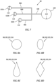
FIGS. 8A-8D are illustrations of various cross-sectional geometries for various cooling circuit elements. -
FIGS. 9A and 9B are schematic illustrations of various manifold arrangements for coupling a plurality of inlet passages with an outlet passage. -
FIG. 10 is a sectional illustration of a portion of a turbine rotor with a circuit outlet in a gas path surface. -
FIG. 11 is a partial, sectional schematic illustration of the rotating assembly with alternative internal cooling circuits. -
FIG. 1 is a partial, sectional schematic illustration of agas turbine engine 20. Thisgas turbine engine 20 ofFIG. 1 is a single spool, radial flow gas turbine engine. Thegas turbine engine 20 may be configured as an auxiliary power unit (APU), a supplemental power unit (SPU) or a primary power unit (PPU) for generating shaft power, electrical power, bleed flow, or other uses for an aircraft. Thegas turbine engine 20 may alternatively be configured as a turbojet gas turbine engine, a turboshaft gas turbine engine, a turboprop gas turbine engine or any other type of gas turbine engine that generates thrust for propelling the aircraft during flight. The present disclosure, however, is not limited to such an exemplary gas turbine engine nor to aircraft propulsion system applications. For example, thegas turbine engine 20 may alternatively include more than one spool and/or be configured in a land based gas turbine engine configured for electrical power generation, an air power generation unit for air mobility, a hybrid power architecture unit, etc. - The
gas turbine engine 20 ofFIG. 1 extends axially along anaxial centerline 22 between a forward,upstream airflow inlet 24 and an aft,downstream airflow exhaust 26. Thisaxial centerline 22 may also be a rotational axis for various components within thegas turbine engine 20. - The
gas turbine engine 20 includes acompressor section 28, acombustor section 30 and aturbine section 32. Thegas turbine engine 20 also includes astatic engine structure 34. Thisstatic engine structure 34 houses thecompressor section 28, thecombustor section 30 and theturbine section 32. Thestatic engine structure 34 ofFIG. 1 also forms theairflow inlet 24 and theairflow exhaust 26. - The
engine sections core flowpath 36 as thecore flowpath 36 extends through thegas turbine engine 20 from theairflow inlet 24 to theairflow exhaust 26. Thecompressor section 28 and theturbine section 32 each include arespective rotor compressor rotor 38 may be configured as a radial flow compressor rotor, which may also be referred to as a radial outflow compressor rotor. Thecompressor rotor 38 ofFIG. 1 , for example, is configured to receive an axial inflow and provide a radial outflow. Thecompressor rotor 38 ofFIG. 1 thereby turns an axial flow radially outward. Similarly, theturbine rotor 40 may be configured as a radial flow turbine rotor, which may also be referred to as a radial inflow turbine rotor. Theturbine rotor 40 ofFIG. 1 , for example, is configured to receive a radial inflow and provide an axial outflow. Theturbine rotor 40 ofFIG. 1 thereby turns a radial flow axially aft. - The
compressor rotor 38 is connected to theturbine rotor 40 through anengine shaft 42. Thisshaft 42 is rotatably supported by thestatic engine structure 34 through a plurality ofbearings 44; e.g., rolling element bearings, thrust bearings, journal bearings, etc. - The
combustor section 30 includes a (e.g., annular)combustor 46 with a (e.g., annular)combustion chamber 48. Thecombustor 46 may be configured as a reverse flow combustor. Inlets ports into thecombustion chamber 48, for example, may be arranged at (e.g., on, adjacent or proximate) and/or towards anaft end 50 of thecombustor 46. Anoutlet 52 from thecombustor 46 may be arranged axially aft of aninlet 54 to theturbine section 32. Thecombustor 46 may also be arranged radially outboard of and/or axially overlap at least a (e.g., aft) portion of theturbine section 32. With this arrangement, thecore flowpath 36 ofFIG. 1 reverses its directions (e.g., from a forward-to-aft direction to an aft-to-forward direction) a first time as thecore flowpath 36 extends into thecombustion chamber 48. The core flowpath 36 ofFIG. 1 then reverses its direction (e.g., from the aft-to-forward direction to the forward-to-aft direction) a second time as thecore flowpath 36 extends from thecombustion chamber 48 into theturbine section 32. The present disclosure, however, is not limited to the foregoing exemplary combustor section arrangement. - During operation, air enters the
gas turbine engine 20 and, more particularly, thecore flowpath 36 through theairflow inlet 24. The air within thecore flowpath 36 may be referred to as core air. This core air is compressed by thecompressor rotor 38 and directed into thecombustion chamber 48. Fuel is injected via one or more fuel injectors (not shown) and mixed with the compressed core air to provide a fuel-air mixture. This fuel-air mixture is ignited within thecombustion chamber 48 via an igniter (not shown), and combustion products thereof flow through theturbine section 32 and cause theturbine rotor 40 to rotate. This rotation of theturbine rotor 40 drives rotation of thecompressor rotor 38 and, thus, compression of the air received from theairflow inlet 24. Anexhaust section 56 of thegas turbine engine 20 receives the combustion products from theturbine section 32. Thisexhaust section 56 directs the received combustion products out of thegas turbine engine 20 through theairflow exhaust 26. - Cycle performance of the
gas turbine engine 20 may be tied to temperature within theturbine section 32. Generally speaking, increasing theturbine section 32 temperature may facilitate increasing gas turbine engine efficiency and/or power generation. However, typical turbine rotor materials may degrade when subject to relatively high turbine section temperatures. A compressor-turbine rotating assembly 58 (e.g., a spool) of the present disclosure therefore is configured with internal cooling to facilitate provision of higher turbine section temperatures and/or operation at elevated turbine section temperatures for longer durations. - Referring to
FIG. 2 , the rotatingassembly 58 includes thecompressor rotor 38, theturbine rotor 40 and theshaft 42. This rotatingassembly 58 also includes one or moreinternal cooling circuits 60 configured to provide the internal cooling to theturbine rotor 40. - The
compressor rotor 38 includes acompressor hub 62 and a plurality ofcompressor blades 64; e.g., compressor vanes. Thecompressor hub 62 ofFIG. 2 extends radially between and to an inner surface 66 (e.g., bore surface) of thecompressor hub 62 and a gas path surface 68 of thecompressor hub 62. The compressorinner surface 66 may form an outer peripheral boundary of aninternal bore 70 within thecompressor rotor 38, which internal compressor bore 70 ofFIG. 2 extends axially through thecompressor rotor 38. Referring toFIG. 1 , the compressor gas path surface 68 may form a (e.g., radial and/or axial) peripheral boundary of thecore flowpath 36 within thecompressor section 28. Referring again toFIG. 2 , thecompressor hub 62 also extends axially between and to the compressor gas path surface 68 and an aft,downstream side surface 72 of thecompressor hub 62. - The
compressor blades 64 are arranged circumferentially about thecompressor hub 62 and theaxial centerline 22 in an annular array. Thecompressor blades 64 are connected to (e.g., formed integral with) thecompressor hub 62. Each of thecompressor blades 64 ofFIG. 2 projects (e.g., axially forward) from thecompressor hub 62 and its compressor gas path surface 68 to aleading edge 74 of therespective compressor blade 64, as well as a (e.g., unsupported, unshrouded)side 76 of therespective compressor blade 64. Each of thecompressor blades 64 ofFIG. 2 also projects (e.g., radially outward) from thecompressor hub 62 and its compressor gas path surface 68 to a trailingedge 78 of therespective compressor blade 64, as well as the respectivecompressor blade side 76. - The
turbine rotor 40 includes aturbine hub 80 and a plurality ofturbine blades 82; e.g., turbine vanes. Theturbine hub 80 ofFIG. 2 extends radially between and to an inner surface 84 (e.g., bore surface) of theturbine hub 80 and a gas path surface 86 of theturbine hub 80. The turbineinner surface 84 may form an outer peripheral boundary of aninternal bore 88 within theturbine rotor 40, which internal turbine bore 88 ofFIG. 2 extends axially through theturbine rotor 40. This internal turbine bore 88 and the internal compressor bore 70 may be parts of a common bore internal to the rotatingassembly 58, which internal rotating assembly bore may extend axially along theaxial centerline 22 through the rotatingassembly 58. Alternatively, the internal turbine bore 88 may be discrete from the internal compressor bore 70. Referring toFIG. 1 , the turbine gas path surface 86 may form a (e.g., radial and/or axial) peripheral boundary of thecore flowpath 36 within theturbine section 32. Referring again toFIG. 2 , theturbine hub 80 also extends axially between and to the turbine gas path surface 86 and a forward,upstream side surface 90 of theturbine hub 80. - The
turbine blades 82 are arranged circumferentially about theturbine hub 80 and theaxial centerline 22 in an annular array. Theturbine blades 82 are connected to (e.g., formed integral with) theturbine hub 80. Each of theturbine blades 82 ofFIG. 2 projects (e.g., radially outward) from theturbine hub 80 and its turbine gas path surface 86 to aleading edge 92 of therespective turbine blade 82, as well as a (e.g., unsupported, unshrouded)side 94 of therespective turbine blade 82. Each of theturbine blades 82 ofFIG. 2 also projects (e.g., axially aft) from theturbine hub 80 and its turbine gas path surface 86 to a trailingedge 96 of therespective turbine blade 82, as well as the respectiveturbine blade side 94. - At least a segment (or an entirety) of the
shaft 42 extends axially along theaxial centerline 22 between thecompressor rotor 38 and itscompressor hub 62 and theturbine rotor 40 and itsturbine hub 80. Theshaft 42 is connected to (e.g., formed integral with) thecompressor rotor 38 and itscompressor hub 62 and theturbine rotor 40 and itsturbine hub 80. Theshaft 42 thereby rotationally couples / links theturbine rotor 40 to thecompressor rotor 38. - Referring to
FIG. 3 , theinternal cooling circuits 60 are arranged circumferentially about theaxial centerline 22 in an annular array. Referring toFIGS. 2 and4 , each of theinternal cooling circuits 60 may include one or more coolingcircuit inlet passages 98A-C (generally referred to as 98) (e.g., capillaries), at least (or only) one cooling circuit outlet passage 100 (e.g., artery), one or morecooling circuit inlets 102A-C (generally referred to as 102), and at least (or only) onecooling circuit outlet 104. - Each of the inlet passages 98 extends longitudinally between and to a respective one of the circuit inlets 102 and the
outlet passage 100. Each inlet passage 98 may be configured into a forward, upstream portion of the rotatingassembly 58, which rotating assembly portion includes one or more of therotating assembly components FIG. 2 , for example, extends from its circuit inlet 102 - through thecompressor rotor 38 and itshub 62, through theshaft 42, and to or into theturbine rotor 40 and its hub 80 - to theoutlet passage 100. Theoutlet passage 100 extends longitudinally between and to the inlet passages 98 and thecircuit outlet 104. Theoutlet passage 100 may be configured into an aft, downstream portion of the rotatingassembly 58, which rotating assembly portion includes at least theturbine rotor 40. Theoutlet passage 100 ofFIG. 2 , for example, extends from the inlet passages 98 - within or through theturbine rotor 40 and its hub 80 - to thecircuit outlet 104. The respectiveinternal cooling circuit 60 and itspassages 98 and 100 thereby extend through (or within) the rotatingassembly 58, and may fluidly couple the circuit inlets 102 to thecircuit outlet 104 in parallel. - Referring to
FIG. 4 , at least a portion or an entirety of one or more or all of theinternal cooling circuits 60 may each spiral about theaxial centerline 22 as the respectiveinternal cooling circuit 60 extends, for example, from one or more or all of its circuit inlets 102 to itscircuit outlet 104. More particularly, one or more or all of the inlet passages 98 may each have a helical geometry. Each inlet passage 98 ofFIG. 4 , for example, extends circumferentially about (e.g., partially or completely around) theaxial centerline 22 as the respective inlet passage 98 extends longitudinally and axially from its circuit inlet 102 to theoutlet passage 100. Theoutlet passage 100 may also or alternatively have a helical geometry. Theoutlet passage 100 ofFIG. 4 , for example, extends circumferentially about (e.g., partially or completely around) theaxial centerline 22 as theoutlet passage 100 extends longitudinally and axially from the inlet passages 98 to theoutlet passage 100. - A pitch of the outlet passage helical geometry may be selected based on cooling requirements for the turbine rotor 40 (see
FIG. 2 ). For example, to increase surface area of theoutlet passage 100 within theturbine rotor 40 and, thus, increase turbine rotor cooling, the pitch of the outlet passage helical geometry may be decreased. By contrast, to decrease the surface area of theoutlet passage 100 within theturbine rotor 40 and, thus, decrease turbine rotor cooling, the pitch of the outlet passage helical geometry may be increased. The pitch of the outlet passage helical geometry may be the same as or different (e.g., less) than a pitch of each inlet passage helical geometry. - Referring to
FIG. 5 , one or more or all of the circuit inlets 102 for a respective internal cooling circuit 60 (seeFIGS. 2 and4 ) may be disposed in the compressor gas path surface 68. With this arrangement, the respective internal cooling circuit 60 (seeFIGS. 2 and4 ) may draw a quantity of the (e.g., relatively cool and pressurized) core air from thecore flowpath 36 within thecompressor section 28 for cooling the rotatingassembly 58 and its turbine rotor 40 (seeFIG. 2 ). The circuit inlets 102 may be distributed along and/or to a (e.g., concave, pressure)side 106 of a respective one of thecompressor blades 64. Thecircuit inlet 102A, for example, may be disposed at a forward,upstream location 108A; e.g., at or about the compressorblade leading edge 74. Thecircuit inlet 102B may be disposed at anintermediate location 108B. Thisintermediate location 108B may be axially spaced aft, downstream from theupstream location 108A along theaxial centerline 22. Theintermediate location 108B may also or alternatively be circumferentially spaced from theupstream location 108A about theaxial centerline 22. Thecircuit inlet 102C may be disposed at an aft,downstream location 108C such that, for example, theintermediate location 108B is between theupstream location 108A and thedownstream location 108C. Thedownstream location 108C may be axially spaced aft, downstream from theintermediate location 108B along theaxial centerline 22. Thedownstream location 108C may also or alternatively be circumferentially spaced from theintermediate location 108B about theaxial centerline 22. - Referring to
FIG. 6 , thecircuit outlet 104 for a respective internal cooling circuit 60 (seeFIGS. 2 and4 ) may be disposed in the turbineinner surface 84. Thecircuit outlet 104 may be disposed at an intermediate location along theturbine rotor 40 leaving, for example, an aft, downstream portion of theturbine rotor 40 and itsturbine hub 80 substantially uncooled. Of course, in other embodiments, the one or more of the internal cooling circuits 60 (seeFIGS. 2 and4 ) may extend further aft, downstream along theturbine rotor 40 and itsturbine hub 80. - Referring to
FIG. 7 , thecircuit outlet 104 and theoutlet passage 100 each have anoutlet size 110; e.g., a diameter, a maximum width, etc. Thisoutlet size 110 may be different (e.g., greater) than an inlet size (e.g., a diameter, a maximum width, etc.) of each circuit inlet 102 and each inlet passage 98. Theoutlet size 110, for example, may be selected such that a cross-sectional area (outlet area) of thecircuit outlet 104 and/or theoutlet passage 100 is exactly or approximately (e.g., +/- 5%) equal to a cross-sectional area (inlet area) of each circuit inlet 102 and/or each inlet passage 98. Of course, in other embodiments, the outlet area may be different (e.g., greater or less) than the inlet area to decelerate or accelerate cooling air flowing through the respectiveinternal cooling circuit 60. - During operation of the rotating
assembly 58 ofFIG. 2 , some of the core air is bled from thecore flowpath 36 within the compressor section 28 (seeFIG. 1 ) and directed into theinternal cooling circuits 60 through the circuit inlets 102 to provide cooling air. This cooling air is directed to theoutlet passages 100. As this cooling air flows through theoutlet passages 100, heat energy is transferred from theturbine rotor 40 and itsturbine hub 80 into the cooling air. The heated cooling air is exhausted from the internal cooling circuits 60 (e.g., into the internal turbine bore 88) through thecircuit outlets 104. Theinternal cooling circuits 60 may thereby utilize some of the relatively cool core air from the compressor section 28 (seeFIG. 1 ) to cool theturbine rotor 40. - In some embodiments, referring to
FIG. 8A , one or more or all of the internalcooling circuit elements FIGS. 8B-D , one or more or all of the internalcooling circuit elements FIG. 8B ), a teardrop shaped cross-sectional geometry (e.g., seeFIG. 8C ), and a polygonal (e.g., diamond shaped, triangular, rectangular, etc.) cross-sectional geometry (e.g., seeFIG. 8D ). The present disclosure, however, is not limited to the foregoing exemplary cross-sectional geometries. In some embodiments, all of the internalcooling circuit elements cooling circuit elements cooling circuit element cooling circuit elements - In some embodiments, referring to
FIGS. 9A and 9B , one or more or all of theinternal cooling circuits 60 may each include a manifold 114 between the one or more inlet passages 98 and theoutlet passage 100. Referring toFIG. 9A , this manifold 114 may have a constant cross-sectional geometry along its longitudinal length. Referring toFIG. 9B , the manifold 114 may alternatively be tapered such that an aera of its cross-sectional geometry increased as more inlet passages 98 are connected. This manifold 114 may be discrete from theoutlet passage 100, or configured as an upstream section of theoutlet passage 100. - In some embodiments, referring to
FIGS. 10 and 11 , one or more or all of thecircuit outlets 104 may each be disposed in the turbine gas path surface 86. - In some embodiments, referring to
FIG. 11 , one or more of theinternal cooling circuits inlet passages single outlet passage circuit outlet turbine rotor 40 as thecircuit inlet compressor rotor 38. For example, where thecircuit inlet 102A is disposed at or about a respective compressorblade leading edge 74, therespective circuit outlet 104A for the sameinternal cooling circuit 60 may be disposed at or about a respective turbineblade trailing edge 96, and so on. With such an arrangement, relatively low pressure core air may be used for cooling a relatively cool portion of theturbine rotor 40 and itsturbine hub 80. By contrast, relatively high pressure core air may be used for cooling a relatively hot portion of theturbine rotor 40 and itsturbine hub 80. - In some embodiments, referring to
FIGS. 1 ,2 and11 , the rotatingassembly 58 and itscomponents assembly 58 and itscomponents - While various embodiments of the present disclosure have been described, it will be apparent to those of ordinary skill in the art that many more embodiments and implementations are possible within the scope of the disclosure. For example, the present disclosure as described herein includes several aspects and embodiments that include particular features. Although these features may be described individually, it is within the scope of the present disclosure that some or all of these features may be combined with any one of the aspects and remain within the scope of the disclosure. Accordingly, the present disclosure is not to be restricted except in light of the attached claims and their equivalents.
Claims (15)
- An assembly (58) for a gas turbine engine (20), comprising:a compressor rotor (38) comprising a gas path surface (68);a turbine rotor (40) rotatable with the compressor rotor (38) about a rotational axis (22); anda cooling circuit (60) comprising an inlet (102) in the gas path surface (68), the cooling circuit (60) extending from the inlet (102), through the compressor rotor (38) and into the turbine rotor (40).
- The assembly of claim 1, further comprising a shaft (42) connected to and extending axially between the compressor rotor (38) and the turbine rotor (40), the cooling circuit (60) extending through the shaft (42) from the compressor rotor (38) to the turbine rotor (40), and/or
further comprising a second cooling circuit (60) comprising a second cooling circuit inlet (102) in the gas path surface (68), the second cooling circuit (60) extending from the second cooling circuit inlet (102), through the compressor rotor (38) and into the turbine rotor (40). - The assembly of claim 1 or 2, wherein at least one ofthe compressor rotor (38) is configured as a radial flow compressor rotor; orthe turbine rotor (40) is configured as a radial flow turbine rotor.
- The assembly of claim 1, 2 or 3, wherein at least the compressor rotor (38) and the turbine rotor (40) are formed together as a monolithic body.
- The assembly of any preceding claim, whereinthe compressor rotor (38) comprises a hub (62) and a plurality of blades (64);the hub (62) comprises the gas path surface (68); andthe plurality of blades (64) are arranged circumferentially about the hub (62), and the plurality of blades (64) project out from the gas path surface (68).
- The assembly of any preceding claim, whereinthe turbine rotor (40) comprises a turbine rotor surface (84); andthe cooling circuit (60) further comprises an outlet (104) in the turbine rotor surface (84, 86), and the cooling circuit (60) extends through the turbine rotor (40) to the outlet (104) fluidly coupling the inlet (102) to the outlet (104).
- The assembly of claim 6, wherein the turbine rotor surface (86) comprises a turbine gas path surface (86).
- The assembly of claim 6 or 7, whereinthe turbine rotor (40) comprises a hub (80) and a plurality of blades (82); andthe plurality of blades (82) are arranged circumferentially about the hub (80), and the plurality of blades (82) project out from the turbine rotor surface (86).
- The assembly of claim 6, wherein the turbine rotor surface (84) forms a peripheral boundary of a bore (88) in the turbine rotor (40).
- The assembly of any of claims 6 to 9, wherein the cooling circuit (60) consists of the inlet (102), the outlet (104) and a passage (98, 100) extending from the inlet (102) to the outlet (104).
- The assembly of any of claims 6 to 10, whereinthe inlet (102) is a first inlet (102A) and the cooling circuit (60) further comprises a second inlet (102B) in the compressor rotor (38); andthe cooling circuit (60) extends from the second inlet (102B), through the compressor rotor (38) and into the turbine rotor (40) fluidly coupling the second inlet (102B) to the outlet (104), wherein, optionally, the second inlet (102B) is in the gas path surface (68).
- The assembly of claim 11, wherein the second inlet (102B) is axially spaced from the first inlet (102A) along the rotational axis (22), and/or the second inlet (102B) is circumferentially spaced from the first inlet (102A) about the rotational axis (22).
- The assembly of claim 11 or 12, whereinthe cooling circuit (60) includes a first capillary (98A), a second capillary (98B) and an artery (100);the first capillary (98A) extends from the first inlet (102A) to the artery (100);the second capillary (98B) extends from the second inlet (102B) to the artery (100); andthe artery (100) extends to the outlet (104).
- The assembly of claim 13, wherein at least one ofthe first capillary (98A) is a helical capillary;the second capillary (98B) is a helical capillary; orthe artery (100) is a helical artery.
- The assembly of any of claims 6 to 14, wherein at least a portion of the cooling circuit (60) spirals about the rotational axis (22) as the cooling circuit extends from the inlet (102A) to the outlet (104).
Applications Claiming Priority (1)
| Application Number | Priority Date | Filing Date | Title |
|---|---|---|---|
| US17/675,564 US12203386B2 (en) | 2022-02-18 | 2022-02-18 | Compressor-turbine rotating assembly with integral cooling circuit(s) |
Publications (2)
| Publication Number | Publication Date |
|---|---|
| EP4230841A1 true EP4230841A1 (en) | 2023-08-23 |
| EP4230841B1 EP4230841B1 (en) | 2025-01-22 |
Family
ID=85283697
Family Applications (1)
| Application Number | Title | Priority Date | Filing Date |
|---|---|---|---|
| EP23157388.2A Active EP4230841B1 (en) | 2022-02-18 | 2023-02-17 | Compressor-turbine rotating assembly with integral cooling circuit(s) |
Country Status (2)
| Country | Link |
|---|---|
| US (1) | US12203386B2 (en) |
| EP (1) | EP4230841B1 (en) |
Cited By (1)
| Publication number | Priority date | Publication date | Assignee | Title |
|---|---|---|---|---|
| CN118481751A (en) * | 2024-06-05 | 2024-08-13 | 南京航空航天大学 | Single-inlet single-outlet fractal cooling runner |
Citations (6)
| Publication number | Priority date | Publication date | Assignee | Title |
|---|---|---|---|---|
| US7785071B1 (en) * | 2007-05-31 | 2010-08-31 | Florida Turbine Technologies, Inc. | Turbine airfoil with spiral trailing edge cooling passages |
| EP2584142A2 (en) * | 2011-10-19 | 2013-04-24 | Honeywell International Inc. | Gas turbine engine cooling systems having hub-bleed impellers and methods for the production thereof |
| EP3216981A1 (en) * | 2016-03-07 | 2017-09-13 | Honeywell International Inc. | Radial turbine blade comprising a diverging-converging cooling passage |
| US20190264612A1 (en) * | 2018-02-27 | 2019-08-29 | GM Global Technology Operations LLC | Turbo vane and compressor for turbocharger |
| US10465603B1 (en) * | 2018-08-01 | 2019-11-05 | GM Global Technology Operations LLC | Turbocharger shafts with integrated cooling fans and turbochargers comprising the same |
| US20220034227A1 (en) * | 2020-08-03 | 2022-02-03 | Rolls-Royce North American Technologies Inc. | Compressor turbine wheel |
Family Cites Families (15)
| Publication number | Priority date | Publication date | Assignee | Title |
|---|---|---|---|---|
| US5605045A (en) * | 1995-09-18 | 1997-02-25 | Turbodyne Systems, Inc. | Turbocharging system with integral assisting electric motor and cooling system therefor |
| US6637500B2 (en) | 2001-10-24 | 2003-10-28 | United Technologies Corporation | Cores for use in precision investment casting |
| US9033670B2 (en) * | 2012-04-11 | 2015-05-19 | Honeywell International Inc. | Axially-split radial turbines and methods for the manufacture thereof |
| US9115586B2 (en) * | 2012-04-19 | 2015-08-25 | Honeywell International Inc. | Axially-split radial turbine |
| US9476305B2 (en) * | 2013-05-13 | 2016-10-25 | Honeywell International Inc. | Impingement-cooled turbine rotor |
| US9683569B2 (en) * | 2015-08-27 | 2017-06-20 | Ingersoll-Rand Company | Compressor system having rotor with distributed coolant conduits and method |
| DE102015117463A1 (en) | 2015-10-14 | 2017-04-20 | Atlas Copco Energas Gmbh | Turbine wheel for a radial turbine |
| CN108699913B (en) * | 2016-03-01 | 2020-05-05 | 西门子股份公司 | Cooling systems for turbine engines |
| DE102017106164A1 (en) * | 2017-03-22 | 2018-09-27 | Iav Gmbh Ingenieurgesellschaft Auto Und Verkehr | turbocharger |
| GB2561837A (en) | 2017-04-24 | 2018-10-31 | Hieta Tech Limited | Turbine rotor, turbine, apparatus and method |
| US20200338639A1 (en) | 2017-11-17 | 2020-10-29 | Kevin Friesth | Advanced Automated Fabrication System And Methods For Thermal And Mechanical Components Utilizing Quadratic Or Squared Hybrid Direct Laser Sintering, Direct Metal Laser Sintering, CNC, Thermal Spraying, Direct Metal Deposition And Frictional Stir Welding. Cross-reference To Related Applications |
| EP3719257B1 (en) | 2018-01-11 | 2024-03-06 | Mitsubishi Heavy Industries Engine & Turbocharger, Ltd. | Turbine wheel for turbochargers, turbocharger and method for producing a turbine wheel for turbochargers |
| US11105212B2 (en) * | 2019-01-29 | 2021-08-31 | Honeywell International Inc. | Gas turbine engines including tangential on-board injectors and methods for manufacturing the same |
| DE102019106733A1 (en) | 2019-03-18 | 2020-09-24 | Man Energy Solutions Se | Cooling of the rotor and stator components of a turbocharger with the help of additively manufactured component-internal cooling channels |
| US11925985B2 (en) | 2019-06-26 | 2024-03-12 | Hamilton Sundstrand Corporation | Method of making a radial turbine wheel using additive manufacturing |
-
2022
- 2022-02-18 US US17/675,564 patent/US12203386B2/en active Active
-
2023
- 2023-02-17 EP EP23157388.2A patent/EP4230841B1/en active Active
Patent Citations (6)
| Publication number | Priority date | Publication date | Assignee | Title |
|---|---|---|---|---|
| US7785071B1 (en) * | 2007-05-31 | 2010-08-31 | Florida Turbine Technologies, Inc. | Turbine airfoil with spiral trailing edge cooling passages |
| EP2584142A2 (en) * | 2011-10-19 | 2013-04-24 | Honeywell International Inc. | Gas turbine engine cooling systems having hub-bleed impellers and methods for the production thereof |
| EP3216981A1 (en) * | 2016-03-07 | 2017-09-13 | Honeywell International Inc. | Radial turbine blade comprising a diverging-converging cooling passage |
| US20190264612A1 (en) * | 2018-02-27 | 2019-08-29 | GM Global Technology Operations LLC | Turbo vane and compressor for turbocharger |
| US10465603B1 (en) * | 2018-08-01 | 2019-11-05 | GM Global Technology Operations LLC | Turbocharger shafts with integrated cooling fans and turbochargers comprising the same |
| US20220034227A1 (en) * | 2020-08-03 | 2022-02-03 | Rolls-Royce North American Technologies Inc. | Compressor turbine wheel |
Cited By (1)
| Publication number | Priority date | Publication date | Assignee | Title |
|---|---|---|---|---|
| CN118481751A (en) * | 2024-06-05 | 2024-08-13 | 南京航空航天大学 | Single-inlet single-outlet fractal cooling runner |
Also Published As
| Publication number | Publication date |
|---|---|
| US20230265761A1 (en) | 2023-08-24 |
| EP4230841B1 (en) | 2025-01-22 |
| US12203386B2 (en) | 2025-01-21 |
Similar Documents
| Publication | Publication Date | Title |
|---|---|---|
| US7631484B2 (en) | High pressure ratio aft fan | |
| US8356469B1 (en) | Gas turbine engine with dual compression rotor | |
| US10830148B2 (en) | Intercooled cooling air with dual pass heat exchanger | |
| CN114991961B (en) | Multi-fluid heat exchanger | |
| US11060530B2 (en) | Compressor cooling in a gas turbine engine | |
| US11492971B2 (en) | Turbine engine system with heat exchanger in bypassable secondary duct | |
| CA2042220A1 (en) | Aft entry cooling system and method for an aircraft engine | |
| US11732656B2 (en) | Turbine engine with soaring air conduit | |
| EP3851632B1 (en) | Gas turbine engine rotor stack with bushing having adaptive airflow temperature metering | |
| US12173651B2 (en) | Pressure control for bifurcated flow of a turbine engine | |
| US9909494B2 (en) | Tip turbine engine with aspirated compressor | |
| EP4230841B1 (en) | Compressor-turbine rotating assembly with integral cooling circuit(s) | |
| US11959390B2 (en) | Gas turbine engine exhaust case with blade shroud and stiffeners | |
| US11873758B1 (en) | Gas turbine engine component with integral heat exchanger | |
| US11732592B2 (en) | Method of cooling a turbine blade | |
| US12624642B2 (en) | Low-pressure turbine | |
| US12338748B1 (en) | Integrated axial compressor diffuser and high pressure turbine vane assembly | |
| US12473835B2 (en) | Vane array structure with recessed stator vanes | |
| US12140048B1 (en) | Integrated centrifugal compressor diffuser and high pressure turbine vane assembly | |
| US12392296B2 (en) | Powerplant with multiple integrated gas turbine engines | |
| US20260022643A1 (en) | Sealing system for a turbomachine | |
| US12234748B2 (en) | Gas turbine engine having outlet guide vanes | |
| EP3587765A1 (en) | Gas turbine engine having a dual pass heat exchanger for cooling cooling air | |
| CA3258849A1 (en) | Integrated centrifugal compressor diffuser and high pressure turbine vane assembly |
Legal Events
| Date | Code | Title | Description |
|---|---|---|---|
| PUAI | Public reference made under article 153(3) epc to a published international application that has entered the european phase |
Free format text: ORIGINAL CODE: 0009012 |
|
| STAA | Information on the status of an ep patent application or granted ep patent |
Free format text: STATUS: THE APPLICATION HAS BEEN PUBLISHED |
|
| AK | Designated contracting states |
Kind code of ref document: A1 Designated state(s): AL AT BE BG CH CY CZ DE DK EE ES FI FR GB GR HR HU IE IS IT LI LT LU LV MC ME MK MT NL NO PL PT RO RS SE SI SK SM TR |
|
| RAP3 | Party data changed (applicant data changed or rights of an application transferred) |
Owner name: RTX CORPORATION |
|
| STAA | Information on the status of an ep patent application or granted ep patent |
Free format text: STATUS: REQUEST FOR EXAMINATION WAS MADE |
|
| 17P | Request for examination filed |
Effective date: 20240223 |
|
| RBV | Designated contracting states (corrected) |
Designated state(s): AL AT BE BG CH CY CZ DE DK EE ES FI FR GB GR HR HU IE IS IT LI LT LU LV MC ME MK MT NL NO PL PT RO RS SE SI SK SM TR |
|
| GRAP | Despatch of communication of intention to grant a patent |
Free format text: ORIGINAL CODE: EPIDOSNIGR1 |
|
| STAA | Information on the status of an ep patent application or granted ep patent |
Free format text: STATUS: GRANT OF PATENT IS INTENDED |
|
| INTG | Intention to grant announced |
Effective date: 20240809 |
|
| GRAS | Grant fee paid |
Free format text: ORIGINAL CODE: EPIDOSNIGR3 |
|
| GRAA | (expected) grant |
Free format text: ORIGINAL CODE: 0009210 |
|
| STAA | Information on the status of an ep patent application or granted ep patent |
Free format text: STATUS: THE PATENT HAS BEEN GRANTED |
|
| AK | Designated contracting states |
Kind code of ref document: B1 Designated state(s): AL AT BE BG CH CY CZ DE DK EE ES FI FR GB GR HR HU IE IS IT LI LT LU LV MC ME MK MT NL NO PL PT RO RS SE SI SK SM TR |
|
| REG | Reference to a national code |
Ref country code: GB Ref legal event code: FG4D |
|
| REG | Reference to a national code |
Ref country code: CH Ref legal event code: EP |
|
| REG | Reference to a national code |
Ref country code: IE Ref legal event code: FG4D |
|
| REG | Reference to a national code |
Ref country code: DE Ref legal event code: R096 Ref document number: 602023001718 Country of ref document: DE |
|
| PGFP | Annual fee paid to national office [announced via postgrant information from national office to epo] |
Ref country code: AT Payment date: 20250417 Year of fee payment: 3 |
|
| REG | Reference to a national code |
Ref country code: NL Ref legal event code: MP Effective date: 20250122 |
|
| PG25 | Lapsed in a contracting state [announced via postgrant information from national office to epo] |
Ref country code: NL Free format text: LAPSE BECAUSE OF FAILURE TO SUBMIT A TRANSLATION OF THE DESCRIPTION OR TO PAY THE FEE WITHIN THE PRESCRIBED TIME-LIMIT Effective date: 20250122 |
|
| PG25 | Lapsed in a contracting state [announced via postgrant information from national office to epo] |
Ref country code: RS Free format text: LAPSE BECAUSE OF FAILURE TO SUBMIT A TRANSLATION OF THE DESCRIPTION OR TO PAY THE FEE WITHIN THE PRESCRIBED TIME-LIMIT Effective date: 20250422 |
|
| PG25 | Lapsed in a contracting state [announced via postgrant information from national office to epo] |
Ref country code: FI Free format text: LAPSE BECAUSE OF FAILURE TO SUBMIT A TRANSLATION OF THE DESCRIPTION OR TO PAY THE FEE WITHIN THE PRESCRIBED TIME-LIMIT Effective date: 20250122 |
|
| PG25 | Lapsed in a contracting state [announced via postgrant information from national office to epo] |
Ref country code: PL Free format text: LAPSE BECAUSE OF FAILURE TO SUBMIT A TRANSLATION OF THE DESCRIPTION OR TO PAY THE FEE WITHIN THE PRESCRIBED TIME-LIMIT Effective date: 20250122 |
|
| PG25 | Lapsed in a contracting state [announced via postgrant information from national office to epo] |
Ref country code: ES Free format text: LAPSE BECAUSE OF FAILURE TO SUBMIT A TRANSLATION OF THE DESCRIPTION OR TO PAY THE FEE WITHIN THE PRESCRIBED TIME-LIMIT Effective date: 20250122 |
|
| REG | Reference to a national code |
Ref country code: LT Ref legal event code: MG9D |
|
| PG25 | Lapsed in a contracting state [announced via postgrant information from national office to epo] |
Ref country code: NO Free format text: LAPSE BECAUSE OF FAILURE TO SUBMIT A TRANSLATION OF THE DESCRIPTION OR TO PAY THE FEE WITHIN THE PRESCRIBED TIME-LIMIT Effective date: 20250422 Ref country code: IS Free format text: LAPSE BECAUSE OF FAILURE TO SUBMIT A TRANSLATION OF THE DESCRIPTION OR TO PAY THE FEE WITHIN THE PRESCRIBED TIME-LIMIT Effective date: 20250522 |
|
| REG | Reference to a national code |
Ref country code: AT Ref legal event code: MK05 Ref document number: 1761614 Country of ref document: AT Kind code of ref document: T Effective date: 20250122 |
|
| PG25 | Lapsed in a contracting state [announced via postgrant information from national office to epo] |
Ref country code: HR Free format text: LAPSE BECAUSE OF FAILURE TO SUBMIT A TRANSLATION OF THE DESCRIPTION OR TO PAY THE FEE WITHIN THE PRESCRIBED TIME-LIMIT Effective date: 20250122 |
|
| PG25 | Lapsed in a contracting state [announced via postgrant information from national office to epo] |
Ref country code: PT Free format text: LAPSE BECAUSE OF FAILURE TO SUBMIT A TRANSLATION OF THE DESCRIPTION OR TO PAY THE FEE WITHIN THE PRESCRIBED TIME-LIMIT Effective date: 20250522 Ref country code: LV Free format text: LAPSE BECAUSE OF FAILURE TO SUBMIT A TRANSLATION OF THE DESCRIPTION OR TO PAY THE FEE WITHIN THE PRESCRIBED TIME-LIMIT Effective date: 20250122 |
|
| PG25 | Lapsed in a contracting state [announced via postgrant information from national office to epo] |
Ref country code: BG Free format text: LAPSE BECAUSE OF FAILURE TO SUBMIT A TRANSLATION OF THE DESCRIPTION OR TO PAY THE FEE WITHIN THE PRESCRIBED TIME-LIMIT Effective date: 20250122 Ref country code: GR Free format text: LAPSE BECAUSE OF FAILURE TO SUBMIT A TRANSLATION OF THE DESCRIPTION OR TO PAY THE FEE WITHIN THE PRESCRIBED TIME-LIMIT Effective date: 20250423 |
|
| PG25 | Lapsed in a contracting state [announced via postgrant information from national office to epo] |
Ref country code: AT Free format text: LAPSE BECAUSE OF FAILURE TO SUBMIT A TRANSLATION OF THE DESCRIPTION OR TO PAY THE FEE WITHIN THE PRESCRIBED TIME-LIMIT Effective date: 20250122 |
|
| PG25 | Lapsed in a contracting state [announced via postgrant information from national office to epo] |
Ref country code: SE Free format text: LAPSE BECAUSE OF FAILURE TO SUBMIT A TRANSLATION OF THE DESCRIPTION OR TO PAY THE FEE WITHIN THE PRESCRIBED TIME-LIMIT Effective date: 20250122 |
|
| PG25 | Lapsed in a contracting state [announced via postgrant information from national office to epo] |
Ref country code: SM Free format text: LAPSE BECAUSE OF FAILURE TO SUBMIT A TRANSLATION OF THE DESCRIPTION OR TO PAY THE FEE WITHIN THE PRESCRIBED TIME-LIMIT Effective date: 20250122 |
|
| PG25 | Lapsed in a contracting state [announced via postgrant information from national office to epo] |
Ref country code: DK Free format text: LAPSE BECAUSE OF FAILURE TO SUBMIT A TRANSLATION OF THE DESCRIPTION OR TO PAY THE FEE WITHIN THE PRESCRIBED TIME-LIMIT Effective date: 20250122 |
|
| PG25 | Lapsed in a contracting state [announced via postgrant information from national office to epo] |
Ref country code: MC Free format text: LAPSE BECAUSE OF FAILURE TO SUBMIT A TRANSLATION OF THE DESCRIPTION OR TO PAY THE FEE WITHIN THE PRESCRIBED TIME-LIMIT Effective date: 20250122 |
|
| PG25 | Lapsed in a contracting state [announced via postgrant information from national office to epo] |
Ref country code: IT Free format text: LAPSE BECAUSE OF FAILURE TO SUBMIT A TRANSLATION OF THE DESCRIPTION OR TO PAY THE FEE WITHIN THE PRESCRIBED TIME-LIMIT Effective date: 20250122 Ref country code: LU Free format text: LAPSE BECAUSE OF NON-PAYMENT OF DUE FEES Effective date: 20250217 |
|
| PG25 | Lapsed in a contracting state [announced via postgrant information from national office to epo] |
Ref country code: CZ Free format text: LAPSE BECAUSE OF FAILURE TO SUBMIT A TRANSLATION OF THE DESCRIPTION OR TO PAY THE FEE WITHIN THE PRESCRIBED TIME-LIMIT Effective date: 20250122 Ref country code: EE Free format text: LAPSE BECAUSE OF FAILURE TO SUBMIT A TRANSLATION OF THE DESCRIPTION OR TO PAY THE FEE WITHIN THE PRESCRIBED TIME-LIMIT Effective date: 20250122 |
|
| REG | Reference to a national code |
Ref country code: DE Ref legal event code: R097 Ref document number: 602023001718 Country of ref document: DE |
|
| PG25 | Lapsed in a contracting state [announced via postgrant information from national office to epo] |
Ref country code: RO Free format text: LAPSE BECAUSE OF FAILURE TO SUBMIT A TRANSLATION OF THE DESCRIPTION OR TO PAY THE FEE WITHIN THE PRESCRIBED TIME-LIMIT Effective date: 20250122 |
|
| PG25 | Lapsed in a contracting state [announced via postgrant information from national office to epo] |
Ref country code: SK Free format text: LAPSE BECAUSE OF FAILURE TO SUBMIT A TRANSLATION OF THE DESCRIPTION OR TO PAY THE FEE WITHIN THE PRESCRIBED TIME-LIMIT Effective date: 20250122 |
|
| PLBE | No opposition filed within time limit |
Free format text: ORIGINAL CODE: 0009261 |
|
| STAA | Information on the status of an ep patent application or granted ep patent |
Free format text: STATUS: NO OPPOSITION FILED WITHIN TIME LIMIT |
|
| REG | Reference to a national code |
Ref country code: BE Ref legal event code: MM Effective date: 20250228 |
|
| 26N | No opposition filed |
Effective date: 20251023 |
|
| PG25 | Lapsed in a contracting state [announced via postgrant information from national office to epo] |
Ref country code: BE Free format text: LAPSE BECAUSE OF NON-PAYMENT OF DUE FEES Effective date: 20250228 |
|
| PG25 | Lapsed in a contracting state [announced via postgrant information from national office to epo] |
Ref country code: IE Free format text: LAPSE BECAUSE OF NON-PAYMENT OF DUE FEES Effective date: 20250217 |
|
| PGFP | Annual fee paid to national office [announced via postgrant information from national office to epo] |
Ref country code: DE Payment date: 20260121 Year of fee payment: 4 |
|
| PGFP | Annual fee paid to national office [announced via postgrant information from national office to epo] |
Ref country code: FR Payment date: 20260121 Year of fee payment: 4 |