EP4230829B1 - An actuation device for a window - Google Patents
An actuation device for a window Download PDFInfo
- Publication number
- EP4230829B1 EP4230829B1 EP23158072.1A EP23158072A EP4230829B1 EP 4230829 B1 EP4230829 B1 EP 4230829B1 EP 23158072 A EP23158072 A EP 23158072A EP 4230829 B1 EP4230829 B1 EP 4230829B1
- Authority
- EP
- European Patent Office
- Prior art keywords
- arm
- actuator element
- actuation device
- blocking element
- actuator
- Prior art date
- Legal status (The legal status is an assumption and is not a legal conclusion. Google has not performed a legal analysis and makes no representation as to the accuracy of the status listed.)
- Active
Links
Images



Classifications
-
- E—FIXED CONSTRUCTIONS
- E05—LOCKS; KEYS; WINDOW OR DOOR FITTINGS; SAFES
- E05F—DEVICES FOR MOVING WINGS INTO OPEN OR CLOSED POSITION; CHECKS FOR WINGS; WING FITTINGS NOT OTHERWISE PROVIDED FOR, CONCERNED WITH THE FUNCTIONING OF THE WING
- E05F15/00—Power-operated mechanisms for wings
- E05F15/60—Power-operated mechanisms for wings using electrical actuators
- E05F15/603—Power-operated mechanisms for wings using electrical actuators using rotary electromotors
- E05F15/611—Power-operated mechanisms for wings using electrical actuators using rotary electromotors for swinging wings
- E05F15/63—Power-operated mechanisms for wings using electrical actuators using rotary electromotors for swinging wings operated by swinging arms
-
- E—FIXED CONSTRUCTIONS
- E05—LOCKS; KEYS; WINDOW OR DOOR FITTINGS; SAFES
- E05D—HINGES OR SUSPENSION DEVICES FOR DOORS, WINDOWS OR WINGS
- E05D15/00—Suspension arrangements for wings
- E05D15/48—Suspension arrangements for wings allowing alternative movements
- E05D15/52—Suspension arrangements for wings allowing alternative movements for opening about a vertical as well as a horizontal axis
-
- E—FIXED CONSTRUCTIONS
- E05—LOCKS; KEYS; WINDOW OR DOOR FITTINGS; SAFES
- E05D—HINGES OR SUSPENSION DEVICES FOR DOORS, WINDOWS OR WINGS
- E05D15/00—Suspension arrangements for wings
- E05D15/48—Suspension arrangements for wings allowing alternative movements
- E05D15/52—Suspension arrangements for wings allowing alternative movements for opening about a vertical as well as a horizontal axis
- E05D15/5205—Suspension arrangements for wings allowing alternative movements for opening about a vertical as well as a horizontal axis with horizontally-extending checks
-
- E—FIXED CONSTRUCTIONS
- E05—LOCKS; KEYS; WINDOW OR DOOR FITTINGS; SAFES
- E05D—HINGES OR SUSPENSION DEVICES FOR DOORS, WINDOWS OR WINGS
- E05D15/00—Suspension arrangements for wings
- E05D15/48—Suspension arrangements for wings allowing alternative movements
- E05D15/52—Suspension arrangements for wings allowing alternative movements for opening about a vertical as well as a horizontal axis
- E05D15/522—Suspension arrangements for wings allowing alternative movements for opening about a vertical as well as a horizontal axis with disconnecting means for the appropriate pivoting parts
-
- E—FIXED CONSTRUCTIONS
- E05—LOCKS; KEYS; WINDOW OR DOOR FITTINGS; SAFES
- E05F—DEVICES FOR MOVING WINGS INTO OPEN OR CLOSED POSITION; CHECKS FOR WINGS; WING FITTINGS NOT OTHERWISE PROVIDED FOR, CONCERNED WITH THE FUNCTIONING OF THE WING
- E05F15/00—Power-operated mechanisms for wings
- E05F15/60—Power-operated mechanisms for wings using electrical actuators
- E05F15/603—Power-operated mechanisms for wings using electrical actuators using rotary electromotors
- E05F15/611—Power-operated mechanisms for wings using electrical actuators using rotary electromotors for swinging wings
- E05F15/616—Power-operated mechanisms for wings using electrical actuators using rotary electromotors for swinging wings operated by push-pull mechanisms
-
- E—FIXED CONSTRUCTIONS
- E05—LOCKS; KEYS; WINDOW OR DOOR FITTINGS; SAFES
- E05F—DEVICES FOR MOVING WINGS INTO OPEN OR CLOSED POSITION; CHECKS FOR WINGS; WING FITTINGS NOT OTHERWISE PROVIDED FOR, CONCERNED WITH THE FUNCTIONING OF THE WING
- E05F15/00—Power-operated mechanisms for wings
- E05F15/60—Power-operated mechanisms for wings using electrical actuators
- E05F15/603—Power-operated mechanisms for wings using electrical actuators using rotary electromotors
- E05F15/611—Power-operated mechanisms for wings using electrical actuators using rotary electromotors for swinging wings
- E05F15/616—Power-operated mechanisms for wings using electrical actuators using rotary electromotors for swinging wings operated by push-pull mechanisms
- E05F15/622—Power-operated mechanisms for wings using electrical actuators using rotary electromotors for swinging wings operated by push-pull mechanisms using screw-and-nut mechanisms
-
- E—FIXED CONSTRUCTIONS
- E05—LOCKS; KEYS; WINDOW OR DOOR FITTINGS; SAFES
- E05Y—INDEXING SCHEME ASSOCIATED WITH SUBCLASSES E05D AND E05F, RELATING TO CONSTRUCTION ELEMENTS, ELECTRIC CONTROL, POWER SUPPLY, POWER SIGNAL OR TRANSMISSION, USER INTERFACES, MOUNTING OR COUPLING, DETAILS, ACCESSORIES, AUXILIARY OPERATIONS NOT OTHERWISE PROVIDED FOR, APPLICATION THEREOF
- E05Y2201/00—Constructional elements; Accessories therefor
- E05Y2201/20—Brakes; Disengaging means; Holders; Stops; Valves; Accessories therefor
- E05Y2201/214—Disengaging means
-
- E—FIXED CONSTRUCTIONS
- E05—LOCKS; KEYS; WINDOW OR DOOR FITTINGS; SAFES
- E05Y—INDEXING SCHEME ASSOCIATED WITH SUBCLASSES E05D AND E05F, RELATING TO CONSTRUCTION ELEMENTS, ELECTRIC CONTROL, POWER SUPPLY, POWER SIGNAL OR TRANSMISSION, USER INTERFACES, MOUNTING OR COUPLING, DETAILS, ACCESSORIES, AUXILIARY OPERATIONS NOT OTHERWISE PROVIDED FOR, APPLICATION THEREOF
- E05Y2201/00—Constructional elements; Accessories therefor
- E05Y2201/20—Brakes; Disengaging means; Holders; Stops; Valves; Accessories therefor
- E05Y2201/218—Holders
-
- E—FIXED CONSTRUCTIONS
- E05—LOCKS; KEYS; WINDOW OR DOOR FITTINGS; SAFES
- E05Y—INDEXING SCHEME ASSOCIATED WITH SUBCLASSES E05D AND E05F, RELATING TO CONSTRUCTION ELEMENTS, ELECTRIC CONTROL, POWER SUPPLY, POWER SIGNAL OR TRANSMISSION, USER INTERFACES, MOUNTING OR COUPLING, DETAILS, ACCESSORIES, AUXILIARY OPERATIONS NOT OTHERWISE PROVIDED FOR, APPLICATION THEREOF
- E05Y2201/00—Constructional elements; Accessories therefor
- E05Y2201/20—Brakes; Disengaging means; Holders; Stops; Valves; Accessories therefor
- E05Y2201/218—Holders
- E05Y2201/22—Locks
-
- E—FIXED CONSTRUCTIONS
- E05—LOCKS; KEYS; WINDOW OR DOOR FITTINGS; SAFES
- E05Y—INDEXING SCHEME ASSOCIATED WITH SUBCLASSES E05D AND E05F, RELATING TO CONSTRUCTION ELEMENTS, ELECTRIC CONTROL, POWER SUPPLY, POWER SIGNAL OR TRANSMISSION, USER INTERFACES, MOUNTING OR COUPLING, DETAILS, ACCESSORIES, AUXILIARY OPERATIONS NOT OTHERWISE PROVIDED FOR, APPLICATION THEREOF
- E05Y2201/00—Constructional elements; Accessories therefor
- E05Y2201/60—Suspension or transmission members; Accessories therefor
- E05Y2201/622—Suspension or transmission members elements
- E05Y2201/624—Arms
-
- E—FIXED CONSTRUCTIONS
- E05—LOCKS; KEYS; WINDOW OR DOOR FITTINGS; SAFES
- E05Y—INDEXING SCHEME ASSOCIATED WITH SUBCLASSES E05D AND E05F, RELATING TO CONSTRUCTION ELEMENTS, ELECTRIC CONTROL, POWER SUPPLY, POWER SIGNAL OR TRANSMISSION, USER INTERFACES, MOUNTING OR COUPLING, DETAILS, ACCESSORIES, AUXILIARY OPERATIONS NOT OTHERWISE PROVIDED FOR, APPLICATION THEREOF
- E05Y2201/00—Constructional elements; Accessories therefor
- E05Y2201/60—Suspension or transmission members; Accessories therefor
- E05Y2201/622—Suspension or transmission members elements
- E05Y2201/628—Bearings
- E05Y2201/636—Universal or ball joints
-
- E—FIXED CONSTRUCTIONS
- E05—LOCKS; KEYS; WINDOW OR DOOR FITTINGS; SAFES
- E05Y—INDEXING SCHEME ASSOCIATED WITH SUBCLASSES E05D AND E05F, RELATING TO CONSTRUCTION ELEMENTS, ELECTRIC CONTROL, POWER SUPPLY, POWER SIGNAL OR TRANSMISSION, USER INTERFACES, MOUNTING OR COUPLING, DETAILS, ACCESSORIES, AUXILIARY OPERATIONS NOT OTHERWISE PROVIDED FOR, APPLICATION THEREOF
- E05Y2201/00—Constructional elements; Accessories therefor
- E05Y2201/60—Suspension or transmission members; Accessories therefor
- E05Y2201/622—Suspension or transmission members elements
- E05Y2201/638—Cams; Ramps
-
- E—FIXED CONSTRUCTIONS
- E05—LOCKS; KEYS; WINDOW OR DOOR FITTINGS; SAFES
- E05Y—INDEXING SCHEME ASSOCIATED WITH SUBCLASSES E05D AND E05F, RELATING TO CONSTRUCTION ELEMENTS, ELECTRIC CONTROL, POWER SUPPLY, POWER SIGNAL OR TRANSMISSION, USER INTERFACES, MOUNTING OR COUPLING, DETAILS, ACCESSORIES, AUXILIARY OPERATIONS NOT OTHERWISE PROVIDED FOR, APPLICATION THEREOF
- E05Y2201/00—Constructional elements; Accessories therefor
- E05Y2201/60—Suspension or transmission members; Accessories therefor
- E05Y2201/622—Suspension or transmission members elements
- E05Y2201/694—Scissor mechanisms
-
- E—FIXED CONSTRUCTIONS
- E05—LOCKS; KEYS; WINDOW OR DOOR FITTINGS; SAFES
- E05Y—INDEXING SCHEME ASSOCIATED WITH SUBCLASSES E05D AND E05F, RELATING TO CONSTRUCTION ELEMENTS, ELECTRIC CONTROL, POWER SUPPLY, POWER SIGNAL OR TRANSMISSION, USER INTERFACES, MOUNTING OR COUPLING, DETAILS, ACCESSORIES, AUXILIARY OPERATIONS NOT OTHERWISE PROVIDED FOR, APPLICATION THEREOF
- E05Y2400/00—Electronic control; Electrical power; Power supply; Power or signal transmission; User interfaces
- E05Y2400/10—Electronic control
- E05Y2400/30—Electronic control of motors
- E05Y2400/3013—Electronic control of motors during manual wing operation
-
- E—FIXED CONSTRUCTIONS
- E05—LOCKS; KEYS; WINDOW OR DOOR FITTINGS; SAFES
- E05Y—INDEXING SCHEME ASSOCIATED WITH SUBCLASSES E05D AND E05F, RELATING TO CONSTRUCTION ELEMENTS, ELECTRIC CONTROL, POWER SUPPLY, POWER SIGNAL OR TRANSMISSION, USER INTERFACES, MOUNTING OR COUPLING, DETAILS, ACCESSORIES, AUXILIARY OPERATIONS NOT OTHERWISE PROVIDED FOR, APPLICATION THEREOF
- E05Y2600/00—Mounting or coupling arrangements for elements provided for in this subclass
- E05Y2600/50—Mounting methods; Positioning
- E05Y2600/52—Toolless
- E05Y2600/528—Hooking, e.g. using bayonets; Locking
-
- E—FIXED CONSTRUCTIONS
- E05—LOCKS; KEYS; WINDOW OR DOOR FITTINGS; SAFES
- E05Y—INDEXING SCHEME ASSOCIATED WITH SUBCLASSES E05D AND E05F, RELATING TO CONSTRUCTION ELEMENTS, ELECTRIC CONTROL, POWER SUPPLY, POWER SIGNAL OR TRANSMISSION, USER INTERFACES, MOUNTING OR COUPLING, DETAILS, ACCESSORIES, AUXILIARY OPERATIONS NOT OTHERWISE PROVIDED FOR, APPLICATION THEREOF
- E05Y2900/00—Application of doors, windows, wings or fittings thereof
- E05Y2900/10—Application of doors, windows, wings or fittings thereof for buildings or parts thereof
- E05Y2900/13—Type of wing
- E05Y2900/148—Windows
Definitions
- the present invention relates to an actuation device for windows of the type comprising a scissor type mechanism and a linear actuator.
- One of the lever arms is connected to the frame of the window and to the window itself at opposite ends.
- the other arm is also connected to the frame and to the first arm in an intermediate position between the ends thereof.
- the actuator acts on the end of the first lever arm, moving this end so as to cause the rotation of the two arms and to obtain the opening of the window.
- the end of the arm connected to the window is further provided with a release mechanism, by means of which the blocking pin of the window is automatically released when the window is in a closed position.
- the same mechanism further allows the pin of the window to be automatically engaged in a first movement step of the actuator of the lever arm.
- a first disadvantage results particularly from the above-described release mechanism which, in the case of inaccurate installation of the opening device, can make opening of the window difficult or in any case not very fluid with turning movement.
- the mechanism does not completely release the pin, thereby bringing about an interference between the pin of the window and the mechanism during the turning opening action thereof.
- the two ends of the arm are vertically misaligned with a misalignment which becomes greater with greater opening of the window and with a smaller height dimension thereof.
- a third disadvantage results from the fact that the device described in EP 1 801 340 requires a design and relevant components which are specific for the different installation requirements, particularly in terms of right/left opening of the window and dimensions thereof.
- the problem addressed by the present invention is to provide an actuation device for windows which is structurally and functionally configured to at least partially overcome one or more of the disadvantages set out with reference to the cited prior art.
- the actuation device for windows provides for the presence of a coupling mechanism which is not automatically opened but instead is only unblocked by means of the motorized actuator of the device. In this manner, the opening of the coupling mechanism has to be carried out manually following the unblocking thereof by acting on the handle of the window.
- the manual action may allow the effective release of the pin and, consequently, a correct opening with turning movement of the window.
- the first arm can actively act in order to bring about the closure of the blocking element while the opening thereof and the resultant removal of the pin can be carried out only by operating manually.
- the first rotary joint which connects the first arm to the runner and the second rotary joint which connects the frame and the second arm are preferably spherical joints.
- the spherical joint advantageously allows a misalignment in a vertical direction between the ends of the arm, thereby allowing an effective opening of the window without excessive stresses for the structure.
- the specific arrangement of the joint further allows the structure to be made readily usable at the frame of the window without affecting the correct operation of the actuator.
- the first arm comprises a main member which includes an initial portion which defines the first end, an end portion which defines the second end and an intermediate portion which connects the initial portion and the end portion and in the region of which there is defined the intermediate zone at which the second arm is connected.
- the initial portion, end portion and intermediate portion are provided with a plurality of connection elements which are configured so as to connect the initial portion, end portion and intermediate portion in different longitudinal positions in a development direction of the first arm and/or in accordance with a different orientation of the intermediate portion with respect to the first and second portions.
- the connection elements comprise a plurality of seats by means of which the portions can be fixed by means of corresponding threaded elements, for example, screws.
- the length of the arm can in fact be varied by acting on the longitudinal connection position, increasing or decreasing the overall extension thereof.
- the possibility of adopting different orientations for the intermediate portion, at which the second arm is joined to the first arm, further allows the production of a configuration which is adapted to both right-hand opening windows and windows having left-hand opening.
- the actuator element and the blocking element comprise respective abutment extensions or other abutment surfaces, the abutment extensions or abutment surfaces being configured so as to be one in contact with the other when the actuator element is in the engagement position and separated from each other when the actuator element is in the disengagement position.
- the actuator element has a flat shape.
- the actuator element comprises an abutment which is configured so as to abut a corresponding first portion of the joint which defines the abutment member and to urge the actuator element into the second position.
- an actuation device for windows according to the present invention is generally designated 100.
- the actuation device 100 is used to bring about the opening and closing of a window I with folding movement.
- the device of the present invention can also be used in the various aspects thereof in windows of different types, such as, for example, bay windows or centre pivoting windows.
- the actuation device 100 comprises a frame 1 which can be fixed to the frame of the window I and a lever mechanism which acts on the window in order to bring about the opening movement.
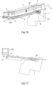
- the actuation of the lever mechanism is advantageously brought about by means of an actuator 5, for example, which is constructed by means of an endless screw mechanism 50, which acts on a runner 3 which is illustrated in Figures 12 and 13 , in order to cause it to slide in the longitudinal direction X which is defined by the frame 1, as schematically illustrated in Figure 10 .
- the lever mechanism further comprises a first arm 2 which is rotatably connected to the runner 3 at a first end 21 thereof and to the window I at a second end 22 thereof.
- the first arm is connected to the window I at one of the closure pins P thereof, that is to say, one of the pins which are typically used in the window for blocking it on the frame when it is in the closed position.
- the first arm 2 is connected to the pin P by means of a relevant coupling mechanism 7 which, as will be seen below, advantageously allows it to be coupled to/uncoupled from the pin P in accordance with the different operating requirements.
- the mechanism 7 will couple the pin during the movement of the window by means of the actuation device 100.
- the mechanism 7 will release the pin, in accordance with methods described in greater detail below.
- the mechanism 7 is further configured in such a manner that, in the absence of any manual action, the pin P remains coupled to the mechanism 7 itself. In other words, until the operator manually acts thereon, for example, by acting on the handle of the window, the first arm 2 remains connected to the pin P by means of the coupling mechanism 7, no automatic action directed towards disconnecting the closure pin P from the coupling mechanism 7 being provided.
- This closure pin P is included in the closure system, with which the window is provided for being blocked in the closed position. Typically, the pin is moved by acting on the handle of the window so as to move it into a disengagement position.
- connection between the first arm 2 and the runner 3 is brought about by means of a rotary joint 6 which, in some embodiments, is constructed in the form of a spherical joint, as may be observed in particular in Figures 10 to 13 .
- the rotary joint 6 comprises a first portion 61 which is connected to the frame 1 and a second portion 62 which is connected to the first end 21 of the first arm 2.
- first and second portions define respective abutment surfaces 64, 65 which are in the form of spherical caps and which are advantageously kept in contact with each other by means of a pin 63 which retains the two portions with respect to each other.
- the two surfaces can slide one on the other and also allow the joint 6, in addition to allowing a rotation about an axis which is defined by the pin 63 itself, to carry out rotational movements about two axes which are perpendicular to the one defined by the pin 63.
- the first arm will be able not only to rotate with respect to the runner and therefore the frame 1, but also to be inclined with respect thereto, as may be observed in Figures 10 and 11 .
- first portion 61 may define an additional abutment surface 66 and the first arm 2 also to comprise a respective abutment surface 26.
- the two surfaces 66 and 26 can also be of spherical cap-like form and can slide one on the other.
- these surfaces have sphericity with a centre arranged in the same position of the surfaces 64 and 65 described above.
- the first portion 61 can be closed in a sandwich-like manner between the first arm 21 and the second portion 62 by means of the pin 63, allowing the structure to be assembled in a simple manner and, at the same time, ensuring a high level of structural robustness.
- the lever mechanism is further formed by a second arm 4 which is rotatably connected to the frame 1.
- the connection to the frame 1 can advantageously be carried out by means of a second rotary joint 6' which preferably has one or more of the features set out in relation to the first rotary joint 6.
- the second arm 4 is further slidingly connected to the first arm 2 at an intermediate zone between the first end 21 and the second end 22 of the first arm 2.
- This sliding connection may be carried out, for example, by providing a guide which is formed on the first and/or second arm and in which a relevant pin which connects the two arms slides.
- the guides are designated 24 and 42, respectively.
- this configuration allows combination of a translational movement in a first movement step of the mechanism and a rotational movement in a second step, thereby optimizing the opening movement of the window.
- the movement of the runner is advantageously brought about by means of an actuator 5 which is constructed, for example, by means of an endless screw mechanism which allows the runner 3 to be actuated in the longitudinal direction X defined by the frame.
- the coupling mechanism 7 comprises an actuator element 71 which can slide with respect to the arm 2, particularly with respect to a main member 20 which forms the structure thereof.
- the mechanism 7 further comprises a blocking element 72 which is rotatably connected to the arm 2 and which allows a housing recess 23 which is intended to receive the closure pin P of the window to be closed or opened.
- the blocking element 72 allows the pin P to be retained or released with respect to the arm 2 in accordance with the position thereof.
- Figure 4 illustrates the blocking element 72 in such a position as to retain the pin P while Figure 7 illustrates the position thereof in which the release is brought about.
- this variation is brought about by means of rotation of the blocking element 72 about a relevant axis Z, this axis Z being illustrated in Figure 4 .
- the axis Z is parallel with a longitudinal development axis of the pin P.
- the actuator element 71 in turn has the function of allowing/preventing the rotation of the blocking element 72.
- the actuator element 71 and the blocking element 72 are preferably capable of mutual engagement.
- the actuator element 71 is movable between a first position, which is illustrated in Figure 4 and in which the actuator element 71 and the blocking element 72 are mutually engaged and in which the rotation of the blocking element 72 is prevented, and a second position, which is illustrated in Figures 6 and 7 and in which the rotation of the blocking element 72 is allowed.
- the actuator element 71 blocks the rotation of the blocking element in accordance with the position of the first pin on the main member 20.
- the actuator element 71 is advantageously movable between a first position, in which the rotation of the blocking element 72 is prevented, and a second position, in which the blocking element 72 is free to rotate with respect to the main member 20 and in a manner independent of the actuator element 71.
- the actuator element 71 and the blocking element 72 comprise a recess 74 and a corresponding shaped portion 75 having a shape which complements the recess 74, which allow the two elements to engage with each other so as to prevent the rotation of the blocking element 72.
- the recess 74 and the shaped portion 75 are formed on the actuator element 71 and the blocking element 72, respectively, but it will be understood that the opposite arrangement may also be provided.
- the actuator element 71 In order to bring about the movement of the actuator element 71, it is configured so as to be able to interact with an abutment member 9 which is connected to the frame 1 and which is preferably defined by the second rotary joint 6', for example, by the respective first portion thereof.
- the abutment member 9 may in fact be configured so as to abut the actuator element while it is sliding along the frame 1.
- the actuator element 71 may have a flat shape and to comprise an abutment 73, at which the contact with the abutment member 9 occurs and by means of which the actuator element 71 is urged into the disengagement position of Figures 6 and 7 .
- the coupling mechanism 7 further comprises a resilient element 78 which is configured so as to urge the actuator element 71 into the engagement position when the abutment member 9 does not act on the actuator element 71.
- the actuator element 71 and the blocking element 72 further comprise respective abutment extensions 76, 77 which are configured so as to be one in contact with the other when the actuator element 71 is in the engagement position and separated from each other when the actuator element 71 is in the disengagement position.
- the abutment extensions also contribute to preventing the rotation of the blocking element 72.
- the blocking element is free to rotate, as may be noted from Figures 6 and 7 .
- the pin P is not automatically released but advantageously it is necessary to act on the handle of the window in order to obtain the rotation of the blocking element 72 and to release the pin P.
- the blocking element 72 has, with respect to the pin, a contact surface which has an inclined or curved shape and which is configured in such a manner that the contact between the pin P and contact surfaces 72A urges the blocking element 72 to rotate, thereby bringing about the opening of the recess 23, illustrated, for example, in Figure 7 .
- the contact surface 72A is advantageously configured so as to urge the blocking element 72 to rotate following contact with the closure pin P so as to open the housing recess 23 and to disengage the closure pin P only following manual stress.
- the rotation of the blocking element 72 is carried out following the movement of the actuator element 71, which is in turn generated by the movement of the runner 3 which allows the first arm 2 to be moved in such a manner that the actuator element 71 is or is not in contact with the abutment element 9.
- the blocking element is urged again to rotate by means of the contact between the extensions 76 and/or 77 and/or by means of the contact between an additional extension 76a and the shaped portion 75 which can therefore have both the function of preventing the rotation of the blocking element 72 when the actuator element 71 is in the engagement position and the function of generating the rotation thereof when the actuator element 71 is in the disengagement position.
- the main member 20 of the first arm 2 includes an initial portion 201 which defines the first end 21, an end portion 202 which defines the second end 22 and an intermediate portion 203 which connects the initial portion 201 and the end portion 202.
- This intermediate portion 203 further defines the intermediate zone at which the second arm 4 is connected to the first arm 2.
- the intermediate portion 203 can advantageously include the guide 24, in which the pin which joins the first arm and second arm slides.
- the initial portion 201, end portion 202 and intermediate portion 203 can be provided with a plurality of connection elements 8 which are configured so as to connect the initial portion 201, end portion 202 and intermediate portion 203 in different positions.
- These different positions may include different longitudinal positions, that is to say, so as to vary the overall length of the first arm 2.
- the different positions may also include a different orientation of the intermediate portion 203.
- the intermediate portion 203 is orientated in opposite manners in one case and the other, thereby advantageously making the window suitable for opening on the right rather than opening on the left.
- connection elements 8 can be constructed in various manners, but in a simpler embodiment thereof they may comprise a plurality of seats 80, by means of which the initial portion, end portion and intermediate portion can be fixed by means of corresponding screws 81 or other similar threaded elements.
- an actuation device is readily adaptable to different configurations, having a structure which is readily adaptable by means of different assembly of the components thereof.
- the provision of the spherical joint allows a solution which is also suitable for windows of mean dimensions to be provided.
- the coupling mechanism provided by the present invention also allows effective operation in the different configurations of the window, reducing the risks of malfunction including in the case of imperfect installations.
Landscapes
- Engineering & Computer Science (AREA)
- Mechanical Engineering (AREA)
- Power-Operated Mechanisms For Wings (AREA)
Description
- The present invention relates to an actuation device for windows of the type comprising a scissor type mechanism and a linear actuator.
- In the scope of the technical field for automation of windows, there are known various solutions for opening windows by means of motorized mechanisms. In particular, it is known to provide mechanisms which are capable of causing a window to carry out an opening and closing folding movement. An example of such mechanisms is described in the European patent application
EP 1801340 , which describes a mechanism which is formed by a lever system which is actuated by means of an actuator. Another example of such a mechanism is described inDE 10 2006 002831 A1 - One of the lever arms is connected to the frame of the window and to the window itself at opposite ends. The other arm is also connected to the frame and to the first arm in an intermediate position between the ends thereof. The actuator acts on the end of the first lever arm, moving this end so as to cause the rotation of the two arms and to obtain the opening of the window.
- The end of the arm connected to the window is further provided with a release mechanism, by means of which the blocking pin of the window is automatically released when the window is in a closed position. The same mechanism further allows the pin of the window to be automatically engaged in a first movement step of the actuator of the lever arm.
- However, this known system, similarly to others with similar characteristics, has a number of disadvantages in terms of versatility and practicality of use.
- A first disadvantage results particularly from the above-described release mechanism which, in the case of inaccurate installation of the opening device, can make opening of the window difficult or in any case not very fluid with turning movement. In fact, it may be the case that the mechanism does not completely release the pin, thereby bringing about an interference between the pin of the window and the mechanism during the turning opening action thereof.
- Another disadvantage results from the fact that the above-mentioned mechanism is not found to be very suitable for windows with mean dimensions and even not recommended in the case of openable fanlights, not being very usable for many applications and generally it is subjected to a state of tension on the lever arm which supports the window when it is in an open position.
- During the inclination movement of the window, in fact, the two ends of the arm are vertically misaligned with a misalignment which becomes greater with greater opening of the window and with a smaller height dimension thereof.
- A third disadvantage results from the fact that the device described in
EP 1 801 340 - However, it would be desirable to make available a solution which is highly versatile and in which common components can be adapted to different installation requirements. Therefore, the problem addressed by the present invention is to provide an actuation device for windows which is structurally and functionally configured to at least partially overcome one or more of the disadvantages set out with reference to the cited prior art.
- According to the invention, a solution to this problem is provided by an actuation device for windows according to
claim 1. - It will be appreciated that the actuation device for windows according to the present invention provides for the presence of a coupling mechanism which is not automatically opened but instead is only unblocked by means of the motorized actuator of the device. In this manner, the opening of the coupling mechanism has to be carried out manually following the unblocking thereof by acting on the handle of the window.
- In this manner, the manual action may allow the effective release of the pin and, consequently, a correct opening with turning movement of the window.
- Therefore, it will be appreciated that the first arm can actively act in order to bring about the closure of the blocking element while the opening thereof and the resultant removal of the pin can be carried out only by operating manually.
- Without a manual action, it is not possible to carry out the separation of the pin from the actuation mechanism.
- However, the prior art uses automatic actuations both for the connection and for the separation of the pin to/from the actuation mechanism.
- The first rotary joint which connects the first arm to the runner and the second rotary joint which connects the frame and the second arm are preferably spherical joints.
- In fact, it will be appreciated that the spherical joint advantageously allows a misalignment in a vertical direction between the ends of the arm, thereby allowing an effective opening of the window without excessive stresses for the structure.
- The specific arrangement of the joint further allows the structure to be made readily usable at the frame of the window without affecting the correct operation of the actuator.
- On the basis of the present aspect, the first arm comprises a main member which includes an initial portion which defines the first end, an end portion which defines the second end and an intermediate portion which connects the initial portion and the end portion and in the region of which there is defined the intermediate zone at which the second arm is connected.
- According to an embodiment of the invention, the initial portion, end portion and intermediate portion are provided with a plurality of connection elements which are configured so as to connect the initial portion, end portion and intermediate portion in different longitudinal positions in a development direction of the first arm and/or in accordance with a different orientation of the intermediate portion with respect to the first and second portions. Preferably, the connection elements comprise a plurality of seats by means of which the portions can be fixed by means of corresponding threaded elements, for example, screws.
- It will be appreciated that the subdivision of the arm into a plurality of portions, which can be connected in accordance with different configurations, advantageously allows the features of the device to be adapted to the different installation requirements.
- The length of the arm can in fact be varied by acting on the longitudinal connection position, increasing or decreasing the overall extension thereof.
- The possibility of adopting different orientations for the intermediate portion, at which the second arm is joined to the first arm, further allows the production of a configuration which is adapted to both right-hand opening windows and windows having left-hand opening.
- According to the invention, the actuator element and the blocking element comprise respective abutment extensions or other abutment surfaces, the abutment extensions or abutment surfaces being configured so as to be one in contact with the other when the actuator element is in the engagement position and separated from each other when the actuator element is in the disengagement position.
- Preferably, the actuator element has a flat shape. Preferably, the actuator element comprises an abutment which is configured so as to abut a corresponding first portion of the joint which defines the abutment member and to urge the actuator element into the second position.
- Preferred characteristics of the invention are further more generally defined by the dependent claims.
- The features and advantages of the invention will be better appreciated from the detailed description of a number of embodiments thereof which are illustrated by way of nonlimiting example with reference to the appended drawings, in which:
-
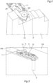
Figure 1 is a perspective view of the actuation device according to an embodiment of the present invention which is installed in an openable folding window; -
Figure 2 is another perspective view of a detail relating to a coupling mechanism of the actuation device ofFigure 1 ; -
Figure 3 is another perspective view which illustrates the coupling mechanism ofFigure 2 which is coupled to a relevant pin of a window, the window not being illustrated for greater clarity of the illustration; -
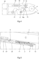
Figure 4 is a plan view of the coupling mechanism ofFigure 2 ; -
Figure 5 is another perspective view of the coupling mechanism ofFigure 2 and a runner of the actuation device of the present invention; -
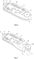
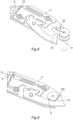
Figures 6 to 9 are perspective views which illustrate different operating steps of the coupling device ofFigure 2 ; -
Figures 10 and 11 are a perspective view and a side view which illustrate the actuation device of an embodiment of the present invention with the window in the closed and open position, respectively; -
Figures 12 and 13 are perspective views which illustrate a spherical joint of the device of an embodiment of the present invention with the window in the closed and open position, respectively; -
Figures 14 and 15 are two perspective views of the device of an embodiment of the present invention, in which an intermediate portion of the first arm is positioned in a position suitable for windows opening on the right and windows for opening on the left. - Initially with reference to
Figure 1 , an actuation device for windows according to the present invention is generally designated 100. - In the embodiment illustrated in the Figures and described in detail below, the
actuation device 100 is used to bring about the opening and closing of a window I with folding movement. - In any case, it will be appreciated that the device of the present invention can also be used in the various aspects thereof in windows of different types, such as, for example, bay windows or centre pivoting windows.
- The
actuation device 100 comprises aframe 1 which can be fixed to the frame of the window I and a lever mechanism which acts on the window in order to bring about the opening movement. - The actuation of the lever mechanism is advantageously brought about by means of an
actuator 5, for example, which is constructed by means of anendless screw mechanism 50, which acts on arunner 3 which is illustrated inFigures 12 and 13 , in order to cause it to slide in the longitudinal direction X which is defined by theframe 1, as schematically illustrated inFigure 10 . - The lever mechanism further comprises a
first arm 2 which is rotatably connected to therunner 3 at afirst end 21 thereof and to the window I at asecond end 22 thereof. - As may be observed in the Figures, the first arm is connected to the window I at one of the closure pins P thereof, that is to say, one of the pins which are typically used in the window for blocking it on the frame when it is in the closed position.
- The
first arm 2 is connected to the pin P by means of arelevant coupling mechanism 7 which, as will be seen below, advantageously allows it to be coupled to/uncoupled from the pin P in accordance with the different operating requirements. In particular, themechanism 7 will couple the pin during the movement of the window by means of theactuation device 100. Vice versa, if it is desirable to carry out manual opening, for example, by acting on the handle of the window, themechanism 7 will release the pin, in accordance with methods described in greater detail below. - The
mechanism 7 is further configured in such a manner that, in the absence of any manual action, the pin P remains coupled to themechanism 7 itself. In other words, until the operator manually acts thereon, for example, by acting on the handle of the window, thefirst arm 2 remains connected to the pin P by means of thecoupling mechanism 7, no automatic action directed towards disconnecting the closure pin P from thecoupling mechanism 7 being provided. - This closure pin P is included in the closure system, with which the window is provided for being blocked in the closed position. Typically, the pin is moved by acting on the handle of the window so as to move it into a disengagement position.
- The connection between the
first arm 2 and therunner 3 is brought about by means of arotary joint 6 which, in some embodiments, is constructed in the form of a spherical joint, as may be observed in particular inFigures 10 to 13 . - In some embodiments, as illustrated, for example, in
Figure 12 , therotary joint 6 comprises afirst portion 61 which is connected to theframe 1 and asecond portion 62 which is connected to thefirst end 21 of thefirst arm 2. - These first and second portions define
respective abutment surfaces pin 63 which retains the two portions with respect to each other. In this manner, the two surfaces can slide one on the other and also allow the joint 6, in addition to allowing a rotation about an axis which is defined by thepin 63 itself, to carry out rotational movements about two axes which are perpendicular to the one defined by thepin 63. - In this manner, the first arm will be able not only to rotate with respect to the runner and therefore the
frame 1, but also to be inclined with respect thereto, as may be observed inFigures 10 and 11 . - Again with reference to
Figures 12 and 13 , it may be observed how in some embodiments there may be provision for thefirst portion 61 to define anadditional abutment surface 66 and thefirst arm 2 also to comprise arespective abutment surface 26. - The two
surfaces surfaces - In this manner, the
first portion 61 can be closed in a sandwich-like manner between thefirst arm 21 and thesecond portion 62 by means of thepin 63, allowing the structure to be assembled in a simple manner and, at the same time, ensuring a high level of structural robustness. - Again with reference to
Figure 1 , the lever mechanism is further formed by asecond arm 4 which is rotatably connected to theframe 1. The connection to theframe 1 can advantageously be carried out by means of a second rotary joint 6' which preferably has one or more of the features set out in relation to the firstrotary joint 6. - The
second arm 4 is further slidingly connected to thefirst arm 2 at an intermediate zone between thefirst end 21 and thesecond end 22 of thefirst arm 2. - This sliding connection may be carried out, for example, by providing a guide which is formed on the first and/or second arm and in which a relevant pin which connects the two arms slides. In the embodiment illustrated in
Figure 1 , the guides are designated 24 and 42, respectively. In this manner, it is possible to obtain relative sliding between the two arms until reaching the end of the guide in such a manner that, in this position, the pin defines a rotation fulcrum between the arms. In other words, this configuration allows combination of a translational movement in a first movement step of the mechanism and a rotational movement in a second step, thereby optimizing the opening movement of the window. As schematically illustrated inFigure 10 , the movement of the runner is advantageously brought about by means of anactuator 5 which is constructed, for example, by means of an endless screw mechanism which allows therunner 3 to be actuated in the longitudinal direction X defined by the frame. - Now with reference to
Figures 2 to 5 , there will be illustrated below embodiments of thecoupling mechanism 7. - As may be observed in the Figures, the
coupling mechanism 7 comprises anactuator element 71 which can slide with respect to thearm 2, particularly with respect to amain member 20 which forms the structure thereof. - The
mechanism 7 further comprises a blockingelement 72 which is rotatably connected to thearm 2 and which allows ahousing recess 23 which is intended to receive the closure pin P of the window to be closed or opened. In other words, the blockingelement 72 allows the pin P to be retained or released with respect to thearm 2 in accordance with the position thereof. For example,Figure 4 illustrates the blockingelement 72 in such a position as to retain the pin P whileFigure 7 illustrates the position thereof in which the release is brought about. As may be appreciated, this variation is brought about by means of rotation of the blockingelement 72 about a relevant axis Z, this axis Z being illustrated inFigure 4 . - Preferably, the axis Z is parallel with a longitudinal development axis of the pin P.
- The
actuator element 71 in turn has the function of allowing/preventing the rotation of the blockingelement 72. In fact, as may be observed inFigure 4 , theactuator element 71 and the blockingelement 72 are preferably capable of mutual engagement. - Advantageously, the
actuator element 71 is movable between a first position, which is illustrated inFigure 4 and in which theactuator element 71 and the blockingelement 72 are mutually engaged and in which the rotation of the blockingelement 72 is prevented, and a second position, which is illustrated inFigures 6 and 7 and in which the rotation of the blockingelement 72 is allowed. - In other words, therefore, the
actuator element 71 blocks the rotation of the blocking element in accordance with the position of the first pin on themain member 20. - Therefore, the
actuator element 71 is advantageously movable between a first position, in which the rotation of the blockingelement 72 is prevented, and a second position, in which the blockingelement 72 is free to rotate with respect to themain member 20 and in a manner independent of theactuator element 71. - Preferably, the
actuator element 71 and the blockingelement 72 comprise arecess 74 and a corresponding shapedportion 75 having a shape which complements therecess 74, which allow the two elements to engage with each other so as to prevent the rotation of the blockingelement 72. - As may be observed in the Figures, the
recess 74 and the shapedportion 75 are formed on theactuator element 71 and the blockingelement 72, respectively, but it will be understood that the opposite arrangement may also be provided. - In order to bring about the movement of the
actuator element 71, it is configured so as to be able to interact with anabutment member 9 which is connected to theframe 1 and which is preferably defined by the second rotary joint 6', for example, by the respective first portion thereof. Theabutment member 9 may in fact be configured so as to abut the actuator element while it is sliding along theframe 1. - In some embodiments, there may be provision for the
actuator element 71 to have a flat shape and to comprise anabutment 73, at which the contact with theabutment member 9 occurs and by means of which theactuator element 71 is urged into the disengagement position ofFigures 6 and 7 . - Preferably, the
coupling mechanism 7 further comprises aresilient element 78 which is configured so as to urge theactuator element 71 into the engagement position when theabutment member 9 does not act on theactuator element 71. - In this manner, during the opening steps of the window, the pin P can be efficiently retained by the
coupling mechanism 7. - According to the invention, the
actuator element 71 and the blockingelement 72 further compriserespective abutment extensions actuator element 71 is in the engagement position and separated from each other when theactuator element 71 is in the disengagement position. As may be observed inFigure 4 , the abutment extensions also contribute to preventing the rotation of the blockingelement 72. Vice versa, when theactuator element 71 is in the disengagement position, the blocking element is free to rotate, as may be noted fromFigures 6 and 7 . - In this case, however, the pin P is not automatically released but advantageously it is necessary to act on the handle of the window in order to obtain the rotation of the blocking
element 72 and to release the pin P. To this end, the blockingelement 72 has, with respect to the pin, a contact surface which has an inclined or curved shape and which is configured in such a manner that the contact between the pin P and contact surfaces 72A urges the blockingelement 72 to rotate, thereby bringing about the opening of therecess 23, illustrated, for example, inFigure 7 . - Therefore, the contact surface 72A is advantageously configured so as to urge the blocking
element 72 to rotate following contact with the closure pin P so as to open thehousing recess 23 and to disengage the closure pin P only following manual stress. - In a conceptually similar manner, when the window is closed, by acting on the handle the pin P returns to the position inside the
recess 23. - The rotation of the blocking
element 72 is carried out following the movement of theactuator element 71, which is in turn generated by the movement of therunner 3 which allows thefirst arm 2 to be moved in such a manner that theactuator element 71 is or is not in contact with theabutment element 9. - The blocking element is urged again to rotate by means of the contact between the
extensions 76 and/or 77 and/or by means of the contact between anadditional extension 76a and the shapedportion 75 which can therefore have both the function of preventing the rotation of the blockingelement 72 when theactuator element 71 is in the engagement position and the function of generating the rotation thereof when theactuator element 71 is in the disengagement position. - Once the
mechanism 7 has been moved back into the position illustrated inFigure 9 , that is to say, with theactuator element 71 in the engagement position, the opening mechanism can be taken up again by theactuator 5 and therelevant arms - An additional aspect of the present invention will be illustrated below in
Figures 14 and 15 . - In these preferred embodiments, the
main member 20 of thefirst arm 2 includes aninitial portion 201 which defines thefirst end 21, anend portion 202 which defines thesecond end 22 and anintermediate portion 203 which connects theinitial portion 201 and theend portion 202. - This
intermediate portion 203 further defines the intermediate zone at which thesecond arm 4 is connected to thefirst arm 2. - Therefore, the
intermediate portion 203 can advantageously include theguide 24, in which the pin which joins the first arm and second arm slides. - In some embodiments, the
initial portion 201,end portion 202 andintermediate portion 203 can be provided with a plurality ofconnection elements 8 which are configured so as to connect theinitial portion 201,end portion 202 andintermediate portion 203 in different positions. - These different positions may include different longitudinal positions, that is to say, so as to vary the overall length of the
first arm 2. - Alternatively or additionally, the different positions may also include a different orientation of the
intermediate portion 203. - As may be observed in
Figures 14 and 15 , for example, theintermediate portion 203 is orientated in opposite manners in one case and the other, thereby advantageously making the window suitable for opening on the right rather than opening on the left. - The
connection elements 8 can be constructed in various manners, but in a simpler embodiment thereof they may comprise a plurality ofseats 80, by means of which the initial portion, end portion and intermediate portion can be fixed by means of correspondingscrews 81 or other similar threaded elements. - Therefore, an actuation device according to the invention is readily adaptable to different configurations, having a structure which is readily adaptable by means of different assembly of the components thereof.
- Furthermore, the provision of the spherical joint allows a solution which is also suitable for windows of mean dimensions to be provided.
- Finally, the coupling mechanism provided by the present invention also allows effective operation in the different configurations of the window, reducing the risks of malfunction including in the case of imperfect installations.
Claims (12)
- An actuation device (100) for a window (I) including a closure pin (P), the actuation device (100) comprising:- a frame (1);- a runner (3) which can slide in a longitudinal direction (X) of the frame (1);- a first arm (2) which is rotatably connected to the runner (3) at a first end (21) thereof and to the window (I) at a second end (22) thereof, the first arm (2) being connected to the runner (3) by means of a first rotary joint (6);- a second arm (4) which is rotatably connected to the frame (1) and which is slidingly connected to the first arm (2) at an intermediate zone between the first end (21) and the second end (22);- an actuator (5) for actuating the runner (3) in the longitudinal direction (X);- wherein the first arm (2) comprises a coupling mechanism (7) which is configured to be coupled/uncoupled to/from a closure pin (P) of the window (I), wherein the coupling mechanism (7) comprises a blocking element (72) which is rotatably connected to a main member (20) of the first arm (2) and which is configured so as to close a housing recess (23) for the closure pin (P) which is formed at the second end (22) of the first arm (2) and an actuator element (71) which is configured to slide with respect to said main member (20), wherein the actuator element (71) and the blocking element (72) are capable of mutual engagement, the actuator element (71) being movable between a first position, in which the actuator element (71) and the blocking element (72) are mutually engaged and the rotation of the blocking element (72) is prevented, and a second position, in which the actuator element (71) and the blocking element (72) are disengaged and the blocking element (72) is free to rotate with respect to the main member (20) and in an independent manner with respect to the actuator element (71), wherein the blocking element (72) comprises a contact surface (72A) which is configured so as to rotate the blocking element (72) following contact with the closure pin (P) so as to open the housing recess (23) and to disengage the closure pin (P) only following a manual stress which is obtained by means of a movement of the closure pin (P), characterized in that the actuator element (71) and the blocking element (72) comprise respective abutment extensions (76, 77) which are configured so as to be one in contact with the other when the actuator element (71) is in the first position and are separated from each other when the actuator element (71) is in the second position.
- An actuation device (100) according to claim 1, wherein the actuator element (71) is configured so as to interact with an abutment member (9) which is connected to the frame (1) following the movement of the runner (3) in the longitudinal direction (X) so as to slide with respect to the main member (20).
- An actuation device (100) according to claim 1 or 2, wherein the actuator element (71) is configured so as to rotate the blocking element (72) so as to couple the closure pin (P) when the actuator element (71) is moved from the second position to the first position and to unblock the blocking element (72), allowing the free rotation thereof but without rotating it when the actuator element (71) is moved from the first position to the second position.
- An actuation device (100) according to any one of the preceding claims, wherein the coupling mechanism (7) comprises a resilient element (78) which is configured so as to urge the actuator element (71) into the first position.
- An actuation device (100) according to claim 4, wherein the actuator element (71) and the blocking element (72) comprise a recess (74) and a corresponding shaped portion (75) having a shape which is complementary with the recess (74), the recess (74) and the shaped portion (75) being formed on the actuator element (71) and the blocking element (72), respectively, or vice versa, and being capable of mutual engagement so as to prevent the rotation of the blocking element (72).
- An actuation device (100) according to any one of the preceding claims when dependent on claim 2, wherein the actuator element (71) has a flat shape and comprises an abutment (73) which is configured so as to abut a corresponding first portion of the joint (6') which defines the abutment member (9) and to urge the actuator element (71) into the second position.
- An actuation device (100) according to any one of the preceding claims, wherein the second arm (4) is connected to the frame (1) by means of a second rotary joint, wherein the first rotary joint (6) and the second rotary joint (6') are spherical joints.
- An actuation device (100) according to claim 7, wherein the first joint comprises a first portion (61) which is connected to the runner (3) and a second portion (62) which is connected to the first end (21) of the first arm (2) and/or the second rotary joint (6') comprises a first portion (61') which is connected to the frame (1) and a second portion which is connected to the second arm (4), the first and second portions of the first joint and/or second joint defining respective abutment surfaces (64, 65) which are formed in the manner of spherical caps and which are able to slide one on the other.
- An actuation device (100) according to claim 7 or 8, wherein the first portion (61) defines an additional abutment surface (66) and the first arm (2) comprises a respective abutment surface (26), the additional abutment surface (66) and the respective surface (26) being formed in the manner of spherical caps and being able to slide one on the other.
- An actuation device (100) according to any one of the preceding claims, wherein the main member of the first arm (2) includes an initial portion (201) which defines the first end (21), an end portion (202) which defines the second end (22) and an intermediate portion (203) which connects the initial portion (201) and an end portion (202) and which defines the intermediate zone at which the second arm (4) is connected to the first arm (2), the initial portion (201), end portion (202) and intermediate portion (203) being provided with a plurality of connection elements (8) which are configured so as to connect the initial portion (201), end portion (202) and intermediate portion (203) in different longitudinal positions in a development direction of the first arm (2) and/or in accordance with a different orientation of the intermediate portion (203) with respect to the first and second portions.
- An actuation device (100) according to claim 10, wherein the connection elements (8) comprise a plurality of seats (80) by means of which the initial portion, end portion and intermediate portion can be fixed by means of corresponding threaded elements (81).
- An actuation device (100) according to any one of the preceding claims, wherein the actuator element (71) is configured so as to be movable in translation with respect to the main member (20) between the first position and the second position.
Applications Claiming Priority (1)
| Application Number | Priority Date | Filing Date | Title |
|---|---|---|---|
| IT202200003236 | 2022-02-22 |
Publications (2)
| Publication Number | Publication Date |
|---|---|
| EP4230829A1 EP4230829A1 (en) | 2023-08-23 |
| EP4230829B1 true EP4230829B1 (en) | 2024-10-30 |
Family
ID=81393060
Family Applications (1)
| Application Number | Title | Priority Date | Filing Date |
|---|---|---|---|
| EP23158072.1A Active EP4230829B1 (en) | 2022-02-22 | 2023-02-22 | An actuation device for a window |
Country Status (1)
| Country | Link |
|---|---|
| EP (1) | EP4230829B1 (en) |
Family Cites Families (5)
| Publication number | Priority date | Publication date | Assignee | Title |
|---|---|---|---|---|
| DE10157094C1 (en) * | 2001-11-16 | 2003-04-24 | Roto Frank Ag | Tip-and-pivot window extender uses power bar connecting element and locking element operated via scissor element to permit manual or powered window maneuvers |
| DE502005008343D1 (en) | 2005-12-20 | 2009-11-26 | Roto Frank Ag | Turning device for a tilting wing, in particular turn-tilt wing |
| DE102006002830B4 (en) * | 2006-01-20 | 2017-06-08 | Roto Frank Ag | Ausstellvorrichtung for the wing of a window or the like |
| DE102006002831B4 (en) * | 2006-01-20 | 2017-05-11 | Roto Frank Ag | Ausstellvorrichtung for the wing of a window or the like |
| DE102007007997B3 (en) * | 2007-02-17 | 2008-04-24 | Roto Frank Ag | Drawing device for e.g. rotary tilting wing, has drawing arm displaced in end region by guiding device in retracted condition such that arm displaces with side in direction of base part in region of connecting link arrangement |
-
2023
- 2023-02-22 EP EP23158072.1A patent/EP4230829B1/en active Active
Also Published As
| Publication number | Publication date |
|---|---|
| EP4230829A1 (en) | 2023-08-23 |
Similar Documents
| Publication | Publication Date | Title |
|---|---|---|
| RU2435013C2 (en) | Auxiliary security module for doors equipped with opening "anti-panic" device | |
| US5337210A (en) | Drawout type switch gear | |
| CN111101784B (en) | Electric release inner compartment (glove box) | |
| US10214944B2 (en) | Opening-and-closing device for vehicle door | |
| EP1335088B1 (en) | Locking device for two structural elements | |
| EP3599331B1 (en) | Cinch override mechanism for latch assembly | |
| PL207454B1 (en) | Opening system for setting half-open a hingedly-mounted rectangular member, in particular a combination hopper-and-swing window sash, door leaf or the like, window furniture for and method of mechanically and manually setting half-open a window sash, door | |
| EP4230829A1 (en) | An actuation device for a window | |
| TW201704620A (en) | Watertight door or window | |
| CN112425017A (en) | Valve mechanism of switch device and switch device thereof | |
| CN113802931B (en) | Electric locking mechanisms for doors and windows, including those with mechanical emergency functions. | |
| EP0015723A1 (en) | Damper operator | |
| US5266759A (en) | Actuator for a step-transformer load switch | |
| EP1764469B1 (en) | Motor-driven window unit with hinged opening | |
| KR20180092293A (en) | Apparatus and method for uniform release effort in a vehicle latch | |
| WO2005033447A2 (en) | Vehicle door lock mechanism | |
| TW202409461A (en) | Valve | |
| KR20190027894A (en) | Cable-operated remote emergency shutdown system | |
| CN112701002A (en) | Three-station operating mechanism | |
| CN112758794B (en) | Linkage device used between elevator door and hall door and elevator system | |
| IT202100012779A1 (en) | Drive device for fixtures | |
| EP1867827A2 (en) | A mechanism for a door of a vehicle | |
| AU2021215243A1 (en) | Hatch assembly | |
| CN217239998U (en) | Switch cabinet | |
| CN223260486U (en) | Switch cabinet |
Legal Events
| Date | Code | Title | Description |
|---|---|---|---|
| PUAI | Public reference made under article 153(3) epc to a published international application that has entered the european phase |
Free format text: ORIGINAL CODE: 0009012 |
|
| STAA | Information on the status of an ep patent application or granted ep patent |
Free format text: STATUS: THE APPLICATION HAS BEEN PUBLISHED |
|
| AK | Designated contracting states |
Kind code of ref document: A1 Designated state(s): AL AT BE BG CH CY CZ DE DK EE ES FI FR GB GR HR HU IE IS IT LI LT LU LV MC ME MK MT NL NO PL PT RO RS SE SI SK SM TR |
|
| STAA | Information on the status of an ep patent application or granted ep patent |
Free format text: STATUS: REQUEST FOR EXAMINATION WAS MADE |
|
| 17P | Request for examination filed |
Effective date: 20240223 |
|
| RBV | Designated contracting states (corrected) |
Designated state(s): AL AT BE BG CH CY CZ DE DK EE ES FI FR GB GR HR HU IE IS IT LI LT LU LV MC ME MK MT NL NO PL PT RO RS SE SI SK SM TR |
|
| GRAP | Despatch of communication of intention to grant a patent |
Free format text: ORIGINAL CODE: EPIDOSNIGR1 |
|
| STAA | Information on the status of an ep patent application or granted ep patent |
Free format text: STATUS: GRANT OF PATENT IS INTENDED |
|
| INTG | Intention to grant announced |
Effective date: 20240524 |
|
| GRAS | Grant fee paid |
Free format text: ORIGINAL CODE: EPIDOSNIGR3 |
|
| GRAA | (expected) grant |
Free format text: ORIGINAL CODE: 0009210 |
|
| STAA | Information on the status of an ep patent application or granted ep patent |
Free format text: STATUS: THE PATENT HAS BEEN GRANTED |
|
| AK | Designated contracting states |
Kind code of ref document: B1 Designated state(s): AL AT BE BG CH CY CZ DE DK EE ES FI FR GB GR HR HU IE IS IT LI LT LU LV MC ME MK MT NL NO PL PT RO RS SE SI SK SM TR |
|
| REG | Reference to a national code |
Ref country code: GB Ref legal event code: FG4D |
|
| REG | Reference to a national code |
Ref country code: CH Ref legal event code: EP |
|
| REG | Reference to a national code |
Ref country code: IE Ref legal event code: FG4D |
|
| REG | Reference to a national code |
Ref country code: DE Ref legal event code: R096 Ref document number: 602023000842 Country of ref document: DE |
|
| REG | Reference to a national code |
Ref country code: LT Ref legal event code: MG9D |
|
| REG | Reference to a national code |
Ref country code: NL Ref legal event code: MP Effective date: 20241030 |
|
| PG25 | Lapsed in a contracting state [announced via postgrant information from national office to epo] |
Ref country code: IS Free format text: LAPSE BECAUSE OF FAILURE TO SUBMIT A TRANSLATION OF THE DESCRIPTION OR TO PAY THE FEE WITHIN THE PRESCRIBED TIME-LIMIT Effective date: 20250228 Ref country code: PT Free format text: LAPSE BECAUSE OF FAILURE TO SUBMIT A TRANSLATION OF THE DESCRIPTION OR TO PAY THE FEE WITHIN THE PRESCRIBED TIME-LIMIT Effective date: 20250228 Ref country code: HR Free format text: LAPSE BECAUSE OF FAILURE TO SUBMIT A TRANSLATION OF THE DESCRIPTION OR TO PAY THE FEE WITHIN THE PRESCRIBED TIME-LIMIT Effective date: 20241030 |
|
| PG25 | Lapsed in a contracting state [announced via postgrant information from national office to epo] |
Ref country code: FI Free format text: LAPSE BECAUSE OF FAILURE TO SUBMIT A TRANSLATION OF THE DESCRIPTION OR TO PAY THE FEE WITHIN THE PRESCRIBED TIME-LIMIT Effective date: 20241030 Ref country code: NL Free format text: LAPSE BECAUSE OF FAILURE TO SUBMIT A TRANSLATION OF THE DESCRIPTION OR TO PAY THE FEE WITHIN THE PRESCRIBED TIME-LIMIT Effective date: 20241030 |
|
| REG | Reference to a national code |
Ref country code: AT Ref legal event code: MK05 Ref document number: 1737022 Country of ref document: AT Kind code of ref document: T Effective date: 20241030 |
|
| PG25 | Lapsed in a contracting state [announced via postgrant information from national office to epo] |
Ref country code: BG Free format text: LAPSE BECAUSE OF FAILURE TO SUBMIT A TRANSLATION OF THE DESCRIPTION OR TO PAY THE FEE WITHIN THE PRESCRIBED TIME-LIMIT Effective date: 20241030 |
|
| PG25 | Lapsed in a contracting state [announced via postgrant information from national office to epo] |
Ref country code: ES Free format text: LAPSE BECAUSE OF FAILURE TO SUBMIT A TRANSLATION OF THE DESCRIPTION OR TO PAY THE FEE WITHIN THE PRESCRIBED TIME-LIMIT Effective date: 20241030 |
|
| PG25 | Lapsed in a contracting state [announced via postgrant information from national office to epo] |
Ref country code: NO Free format text: LAPSE BECAUSE OF FAILURE TO SUBMIT A TRANSLATION OF THE DESCRIPTION OR TO PAY THE FEE WITHIN THE PRESCRIBED TIME-LIMIT Effective date: 20250130 |
|
| PG25 | Lapsed in a contracting state [announced via postgrant information from national office to epo] |
Ref country code: AT Free format text: LAPSE BECAUSE OF FAILURE TO SUBMIT A TRANSLATION OF THE DESCRIPTION OR TO PAY THE FEE WITHIN THE PRESCRIBED TIME-LIMIT Effective date: 20241030 Ref country code: LV Free format text: LAPSE BECAUSE OF FAILURE TO SUBMIT A TRANSLATION OF THE DESCRIPTION OR TO PAY THE FEE WITHIN THE PRESCRIBED TIME-LIMIT Effective date: 20241030 Ref country code: GR Free format text: LAPSE BECAUSE OF FAILURE TO SUBMIT A TRANSLATION OF THE DESCRIPTION OR TO PAY THE FEE WITHIN THE PRESCRIBED TIME-LIMIT Effective date: 20250131 |
|
| PG25 | Lapsed in a contracting state [announced via postgrant information from national office to epo] |
Ref country code: PL Free format text: LAPSE BECAUSE OF FAILURE TO SUBMIT A TRANSLATION OF THE DESCRIPTION OR TO PAY THE FEE WITHIN THE PRESCRIBED TIME-LIMIT Effective date: 20241030 |
|
| PG25 | Lapsed in a contracting state [announced via postgrant information from national office to epo] |
Ref country code: RS Free format text: LAPSE BECAUSE OF FAILURE TO SUBMIT A TRANSLATION OF THE DESCRIPTION OR TO PAY THE FEE WITHIN THE PRESCRIBED TIME-LIMIT Effective date: 20250130 |
|
| PG25 | Lapsed in a contracting state [announced via postgrant information from national office to epo] |
Ref country code: SM Free format text: LAPSE BECAUSE OF FAILURE TO SUBMIT A TRANSLATION OF THE DESCRIPTION OR TO PAY THE FEE WITHIN THE PRESCRIBED TIME-LIMIT Effective date: 20241030 |
|
| PG25 | Lapsed in a contracting state [announced via postgrant information from national office to epo] |
Ref country code: DK Free format text: LAPSE BECAUSE OF FAILURE TO SUBMIT A TRANSLATION OF THE DESCRIPTION OR TO PAY THE FEE WITHIN THE PRESCRIBED TIME-LIMIT Effective date: 20241030 |
|
| PG25 | Lapsed in a contracting state [announced via postgrant information from national office to epo] |
Ref country code: EE Free format text: LAPSE BECAUSE OF FAILURE TO SUBMIT A TRANSLATION OF THE DESCRIPTION OR TO PAY THE FEE WITHIN THE PRESCRIBED TIME-LIMIT Effective date: 20241030 |
|
| PG25 | Lapsed in a contracting state [announced via postgrant information from national office to epo] |
Ref country code: RO Free format text: LAPSE BECAUSE OF FAILURE TO SUBMIT A TRANSLATION OF THE DESCRIPTION OR TO PAY THE FEE WITHIN THE PRESCRIBED TIME-LIMIT Effective date: 20241030 |
|
| PG25 | Lapsed in a contracting state [announced via postgrant information from national office to epo] |
Ref country code: SK Free format text: LAPSE BECAUSE OF FAILURE TO SUBMIT A TRANSLATION OF THE DESCRIPTION OR TO PAY THE FEE WITHIN THE PRESCRIBED TIME-LIMIT Effective date: 20241030 |
|
| PG25 | Lapsed in a contracting state [announced via postgrant information from national office to epo] |
Ref country code: CZ Free format text: LAPSE BECAUSE OF FAILURE TO SUBMIT A TRANSLATION OF THE DESCRIPTION OR TO PAY THE FEE WITHIN THE PRESCRIBED TIME-LIMIT Effective date: 20241030 |
|
| REG | Reference to a national code |
Ref country code: DE Ref legal event code: R097 Ref document number: 602023000842 Country of ref document: DE |
|
| PLBE | No opposition filed within time limit |
Free format text: ORIGINAL CODE: 0009261 |
|
| STAA | Information on the status of an ep patent application or granted ep patent |
Free format text: STATUS: NO OPPOSITION FILED WITHIN TIME LIMIT |
|
| PG25 | Lapsed in a contracting state [announced via postgrant information from national office to epo] |
Ref country code: SE Free format text: LAPSE BECAUSE OF FAILURE TO SUBMIT A TRANSLATION OF THE DESCRIPTION OR TO PAY THE FEE WITHIN THE PRESCRIBED TIME-LIMIT Effective date: 20241030 |
|
| PG25 | Lapsed in a contracting state [announced via postgrant information from national office to epo] |
Ref country code: MC Free format text: LAPSE BECAUSE OF FAILURE TO SUBMIT A TRANSLATION OF THE DESCRIPTION OR TO PAY THE FEE WITHIN THE PRESCRIBED TIME-LIMIT Effective date: 20241030 |
|
| 26N | No opposition filed |
Effective date: 20250731 |
|
| PG25 | Lapsed in a contracting state [announced via postgrant information from national office to epo] |
Ref country code: LU Free format text: LAPSE BECAUSE OF NON-PAYMENT OF DUE FEES Effective date: 20250222 |
|
| REG | Reference to a national code |
Ref country code: BE Ref legal event code: MM Effective date: 20250228 |
|
| PG25 | Lapsed in a contracting state [announced via postgrant information from national office to epo] |
Ref country code: FR Free format text: LAPSE BECAUSE OF NON-PAYMENT OF DUE FEES Effective date: 20250228 |
|
| PG25 | Lapsed in a contracting state [announced via postgrant information from national office to epo] |
Ref country code: BE Free format text: LAPSE BECAUSE OF NON-PAYMENT OF DUE FEES Effective date: 20250228 |
|
| PG25 | Lapsed in a contracting state [announced via postgrant information from national office to epo] |
Ref country code: IE Free format text: LAPSE BECAUSE OF NON-PAYMENT OF DUE FEES Effective date: 20250222 |
|
| PGFP | Annual fee paid to national office [announced via postgrant information from national office to epo] |
Ref country code: DE Payment date: 20260218 Year of fee payment: 4 |
|
| PGFP | Annual fee paid to national office [announced via postgrant information from national office to epo] |
Ref country code: IT Payment date: 20260228 Year of fee payment: 4 |