EP4230587A1 - Tungsten oxide and oxygen evolution reaction catalyst - Google Patents
Tungsten oxide and oxygen evolution reaction catalyst Download PDFInfo
- Publication number
- EP4230587A1 EP4230587A1 EP21879995.5A EP21879995A EP4230587A1 EP 4230587 A1 EP4230587 A1 EP 4230587A1 EP 21879995 A EP21879995 A EP 21879995A EP 4230587 A1 EP4230587 A1 EP 4230587A1
- Authority
- EP
- European Patent Office
- Prior art keywords
- tungsten oxide
- electrode
- carbon dioxide
- electrode chamber
- catalyst
- Prior art date
- Legal status (The legal status is an assumption and is not a legal conclusion. Google has not performed a legal analysis and makes no representation as to the accuracy of the status listed.)
- Pending
Links
Images








Classifications
-
- C—CHEMISTRY; METALLURGY
- C25—ELECTROLYTIC OR ELECTROPHORETIC PROCESSES; APPARATUS THEREFOR
- C25B—ELECTROLYTIC OR ELECTROPHORETIC PROCESSES FOR THE PRODUCTION OF COMPOUNDS OR NON-METALS; APPARATUS THEREFOR
- C25B11/00—Electrodes; Manufacture thereof not otherwise provided for
- C25B11/04—Electrodes; Manufacture thereof not otherwise provided for characterised by the material
- C25B11/051—Electrodes formed of electrocatalysts on a substrate or carrier
- C25B11/073—Electrodes formed of electrocatalysts on a substrate or carrier characterised by the electrocatalyst material
- C25B11/075—Electrodes formed of electrocatalysts on a substrate or carrier characterised by the electrocatalyst material consisting of a single catalytic element or catalytic compound
- C25B11/077—Electrodes formed of electrocatalysts on a substrate or carrier characterised by the electrocatalyst material consisting of a single catalytic element or catalytic compound the compound being a non-noble metal oxide
-
- B—PERFORMING OPERATIONS; TRANSPORTING
- B01—PHYSICAL OR CHEMICAL PROCESSES OR APPARATUS IN GENERAL
- B01J—CHEMICAL OR PHYSICAL PROCESSES, e.g. CATALYSIS OR COLLOID CHEMISTRY; THEIR RELEVANT APPARATUS
- B01J23/00—Catalysts comprising metals or metal oxides or hydroxides, not provided for in group B01J21/00
- B01J23/70—Catalysts comprising metals or metal oxides or hydroxides, not provided for in group B01J21/00 of the iron group metals or copper
- B01J23/76—Catalysts comprising metals or metal oxides or hydroxides, not provided for in group B01J21/00 of the iron group metals or copper combined with metals, oxides or hydroxides provided for in groups B01J23/02 - B01J23/36
- B01J23/84—Catalysts comprising metals or metal oxides or hydroxides, not provided for in group B01J21/00 of the iron group metals or copper combined with metals, oxides or hydroxides provided for in groups B01J23/02 - B01J23/36 with arsenic, antimony, bismuth, vanadium, niobium, tantalum, polonium, chromium, molybdenum, tungsten, manganese, technetium or rhenium
- B01J23/85—Chromium, molybdenum or tungsten
- B01J23/888—Tungsten
-
- B—PERFORMING OPERATIONS; TRANSPORTING
- B01—PHYSICAL OR CHEMICAL PROCESSES OR APPARATUS IN GENERAL
- B01J—CHEMICAL OR PHYSICAL PROCESSES, e.g. CATALYSIS OR COLLOID CHEMISTRY; THEIR RELEVANT APPARATUS
- B01J37/00—Processes, in general, for preparing catalysts; Processes, in general, for activation of catalysts
- B01J37/08—Heat treatment
-
- B—PERFORMING OPERATIONS; TRANSPORTING
- B01—PHYSICAL OR CHEMICAL PROCESSES OR APPARATUS IN GENERAL
- B01J—CHEMICAL OR PHYSICAL PROCESSES, e.g. CATALYSIS OR COLLOID CHEMISTRY; THEIR RELEVANT APPARATUS
- B01J37/00—Processes, in general, for preparing catalysts; Processes, in general, for activation of catalysts
- B01J37/08—Heat treatment
- B01J37/10—Heat treatment in the presence of water, e.g. steam
-
- C—CHEMISTRY; METALLURGY
- C01—INORGANIC CHEMISTRY
- C01B—NON-METALLIC ELEMENTS; COMPOUNDS THEREOF; METALLOIDS OR COMPOUNDS THEREOF NOT COVERED BY SUBCLASS C01C
- C01B13/00—Oxygen; Ozone; Oxides or hydroxides in general
- C01B13/14—Methods for preparing oxides or hydroxides in general
- C01B13/32—Methods for preparing oxides or hydroxides in general by oxidation or hydrolysis of elements or compounds in the liquid or solid state or in non-aqueous solution, e.g. sol-gel process
-
- C—CHEMISTRY; METALLURGY
- C01—INORGANIC CHEMISTRY
- C01G—COMPOUNDS CONTAINING METALS NOT COVERED BY SUBCLASSES C01D OR C01F
- C01G41/00—Compounds of tungsten
- C01G41/02—Oxides; Hydroxides
-
- C—CHEMISTRY; METALLURGY
- C01—INORGANIC CHEMISTRY
- C01G—COMPOUNDS CONTAINING METALS NOT COVERED BY SUBCLASSES C01D OR C01F
- C01G53/00—Compounds of nickel
-
- C—CHEMISTRY; METALLURGY
- C01—INORGANIC CHEMISTRY
- C01G—COMPOUNDS CONTAINING METALS NOT COVERED BY SUBCLASSES C01D OR C01F
- C01G53/00—Compounds of nickel
- C01G53/40—Complex oxides containing nickel and at least one other metal element
-
- C—CHEMISTRY; METALLURGY
- C01—INORGANIC CHEMISTRY
- C01G—COMPOUNDS CONTAINING METALS NOT COVERED BY SUBCLASSES C01D OR C01F
- C01G53/00—Compounds of nickel
- C01G53/80—Compounds containing nickel, with or without oxygen or hydrogen, and containing one or more other elements
- C01G53/82—Compounds containing nickel, with or without oxygen or hydrogen, and containing two or more other elements
-
- C—CHEMISTRY; METALLURGY
- C25—ELECTROLYTIC OR ELECTROPHORETIC PROCESSES; APPARATUS THEREFOR
- C25B—ELECTROLYTIC OR ELECTROPHORETIC PROCESSES FOR THE PRODUCTION OF COMPOUNDS OR NON-METALS; APPARATUS THEREFOR
- C25B1/00—Electrolytic production of inorganic compounds or non-metals
- C25B1/01—Products
- C25B1/02—Hydrogen or oxygen
- C25B1/04—Hydrogen or oxygen by electrolysis of water
-
- C—CHEMISTRY; METALLURGY
- C25—ELECTROLYTIC OR ELECTROPHORETIC PROCESSES; APPARATUS THEREFOR
- C25B—ELECTROLYTIC OR ELECTROPHORETIC PROCESSES FOR THE PRODUCTION OF COMPOUNDS OR NON-METALS; APPARATUS THEREFOR
- C25B1/00—Electrolytic production of inorganic compounds or non-metals
- C25B1/01—Products
- C25B1/23—Carbon monoxide or syngas
-
- C—CHEMISTRY; METALLURGY
- C25—ELECTROLYTIC OR ELECTROPHORETIC PROCESSES; APPARATUS THEREFOR
- C25B—ELECTROLYTIC OR ELECTROPHORETIC PROCESSES FOR THE PRODUCTION OF COMPOUNDS OR NON-METALS; APPARATUS THEREFOR
- C25B11/00—Electrodes; Manufacture thereof not otherwise provided for
- C25B11/04—Electrodes; Manufacture thereof not otherwise provided for characterised by the material
-
- C—CHEMISTRY; METALLURGY
- C25—ELECTROLYTIC OR ELECTROPHORETIC PROCESSES; APPARATUS THEREFOR
- C25B—ELECTROLYTIC OR ELECTROPHORETIC PROCESSES FOR THE PRODUCTION OF COMPOUNDS OR NON-METALS; APPARATUS THEREFOR
- C25B11/00—Electrodes; Manufacture thereof not otherwise provided for
- C25B11/04—Electrodes; Manufacture thereof not otherwise provided for characterised by the material
- C25B11/051—Electrodes formed of electrocatalysts on a substrate or carrier
- C25B11/073—Electrodes formed of electrocatalysts on a substrate or carrier characterised by the electrocatalyst material
-
- C—CHEMISTRY; METALLURGY
- C25—ELECTROLYTIC OR ELECTROPHORETIC PROCESSES; APPARATUS THEREFOR
- C25B—ELECTROLYTIC OR ELECTROPHORETIC PROCESSES FOR THE PRODUCTION OF COMPOUNDS OR NON-METALS; APPARATUS THEREFOR
- C25B15/00—Operating or servicing cells
- C25B15/08—Supplying or removing reactants or electrolytes; Regeneration of electrolytes
-
- C—CHEMISTRY; METALLURGY
- C25—ELECTROLYTIC OR ELECTROPHORETIC PROCESSES; APPARATUS THEREFOR
- C25B—ELECTROLYTIC OR ELECTROPHORETIC PROCESSES FOR THE PRODUCTION OF COMPOUNDS OR NON-METALS; APPARATUS THEREFOR
- C25B3/00—Electrolytic production of organic compounds
- C25B3/20—Processes
- C25B3/25—Reduction
-
- C—CHEMISTRY; METALLURGY
- C25—ELECTROLYTIC OR ELECTROPHORETIC PROCESSES; APPARATUS THEREFOR
- C25B—ELECTROLYTIC OR ELECTROPHORETIC PROCESSES FOR THE PRODUCTION OF COMPOUNDS OR NON-METALS; APPARATUS THEREFOR
- C25B9/00—Cells or assemblies of cells; Constructional parts of cells; Assemblies of constructional parts, e.g. electrode-diaphragm assemblies; Process-related cell features
- C25B9/17—Cells comprising dimensionally-stable non-movable electrodes; Assemblies of constructional parts thereof
- C25B9/19—Cells comprising dimensionally-stable non-movable electrodes; Assemblies of constructional parts thereof with diaphragms
-
- C—CHEMISTRY; METALLURGY
- C25—ELECTROLYTIC OR ELECTROPHORETIC PROCESSES; APPARATUS THEREFOR
- C25B—ELECTROLYTIC OR ELECTROPHORETIC PROCESSES FOR THE PRODUCTION OF COMPOUNDS OR NON-METALS; APPARATUS THEREFOR
- C25B9/00—Cells or assemblies of cells; Constructional parts of cells; Assemblies of constructional parts, e.g. electrode-diaphragm assemblies; Process-related cell features
- C25B9/17—Cells comprising dimensionally-stable non-movable electrodes; Assemblies of constructional parts thereof
- C25B9/19—Cells comprising dimensionally-stable non-movable electrodes; Assemblies of constructional parts thereof with diaphragms
- C25B9/23—Cells comprising dimensionally-stable non-movable electrodes; Assemblies of constructional parts thereof with diaphragms comprising ion-exchange membranes in or on which electrode material is embedded
-
- B—PERFORMING OPERATIONS; TRANSPORTING
- B01—PHYSICAL OR CHEMICAL PROCESSES OR APPARATUS IN GENERAL
- B01J—CHEMICAL OR PHYSICAL PROCESSES, e.g. CATALYSIS OR COLLOID CHEMISTRY; THEIR RELEVANT APPARATUS
- B01J2523/00—Constitutive chemical elements of heterogeneous catalysts
-
- C—CHEMISTRY; METALLURGY
- C01—INORGANIC CHEMISTRY
- C01P—INDEXING SCHEME RELATING TO STRUCTURAL AND PHYSICAL ASPECTS OF SOLID INORGANIC COMPOUNDS
- C01P2002/00—Crystal-structural characteristics
- C01P2002/70—Crystal-structural characteristics defined by measured X-ray, neutron or electron diffraction data
- C01P2002/72—Crystal-structural characteristics defined by measured X-ray, neutron or electron diffraction data by d-values or two theta-values, e.g. as X-ray diagram
-
- Y—GENERAL TAGGING OF NEW TECHNOLOGICAL DEVELOPMENTS; GENERAL TAGGING OF CROSS-SECTIONAL TECHNOLOGIES SPANNING OVER SEVERAL SECTIONS OF THE IPC; TECHNICAL SUBJECTS COVERED BY FORMER USPC CROSS-REFERENCE ART COLLECTIONS [XRACs] AND DIGESTS
- Y02—TECHNOLOGIES OR APPLICATIONS FOR MITIGATION OR ADAPTATION AGAINST CLIMATE CHANGE
- Y02E—REDUCTION OF GREENHOUSE GAS [GHG] EMISSIONS, RELATED TO ENERGY GENERATION, TRANSMISSION OR DISTRIBUTION
- Y02E60/00—Enabling technologies; Technologies with a potential or indirect contribution to GHG emissions mitigation
- Y02E60/30—Hydrogen technology
- Y02E60/36—Hydrogen production from non-carbon containing sources, e.g. by water electrolysis
-
- Y—GENERAL TAGGING OF NEW TECHNOLOGICAL DEVELOPMENTS; GENERAL TAGGING OF CROSS-SECTIONAL TECHNOLOGIES SPANNING OVER SEVERAL SECTIONS OF THE IPC; TECHNICAL SUBJECTS COVERED BY FORMER USPC CROSS-REFERENCE ART COLLECTIONS [XRACs] AND DIGESTS
- Y02—TECHNOLOGIES OR APPLICATIONS FOR MITIGATION OR ADAPTATION AGAINST CLIMATE CHANGE
- Y02P—CLIMATE CHANGE MITIGATION TECHNOLOGIES IN THE PRODUCTION OR PROCESSING OF GOODS
- Y02P20/00—Technologies relating to chemical industry
- Y02P20/10—Process efficiency
- Y02P20/133—Renewable energy sources, e.g. sunlight
Definitions
- the present invention relates to tungsten oxide represented by Ni x Fe 1-x WO 4 (wherein 0 ⁇ x ⁇ 1), a catalyst for oxygen evolution reaction comprising the tungsten oxide, and a method for producing the tungsten oxide.
- the entire system can be miniaturized by enhancing a current density upon electrolysis in an electrolyzer, resulting in enabling significant reduction of equipment cost. Therefore, development of a catalyst capable of reducing the power losses has been desired.
- Non-patent Document 1 describes Co 1-x Fe x WO 4 -CNT, a composite of Co 1-x Fe x WO 4 and carbon nanotubes (CNTs), which is used as an oxygen evolution reaction (OER) catalyst.
- Non-patent Document 2 reports use of Ni-Fe-W hydroxide as a catalyst for OER, and it is also composited with carbon fibers. Therefore, there has been demand for a compound that exhibits high catalytic activity without using precious metals such as ruthenium and iridium.
- An object of the present invention is to provide a compound with high catalytic activity that can be used as a catalyst for oxygen evolution reaction.
- the present inventors investigated a new compound with high catalytic activity that can be used as a catalyst for oxygen evolution reaction and have found that the compound represented by Ni x Fe 1-x WO 4 (wherein 0 ⁇ x ⁇ 1) has very high catalytic activity.
- the compound represented by Ni x Fe 1-x WO 4 (wherein 0 ⁇ x ⁇ 1) has very high catalytic activity.
- the tungsten oxide of the present invention exhibits excellent catalytic activity when used as a catalyst for oxygen evolution reaction.
- the catalyst for oxygen evolution reaction of the present invention exhibits excellent catalytic activity by comprising the tungsten oxide of the present invention.
- the production method of the present invention can produce the tungsten oxide of the present invention.
- the tungsten oxide of the present invention is the compound represented by the chemical formula Ni x Fe 1-x WO 4 (wherein 0 ⁇ x ⁇ 1).
- x is preferably 0.05 or more and 0.95 or less, preferably 0.10 or more and 0.90 or less, preferably 0.15 or more and 0.85 or less, preferably 0.2 or more and 0.8 or less, and more preferably 0.4 or more and 0.6 or less.
- ruthenium oxide, iridium oxide, and the like have been used as catalysts for oxygen evolution reaction, but the tungsten oxide of the present invention is superior in cost because it has a catalytic effect on oxygen evolution reaction without using precious metals such as ruthenium and iridium.
- tungsten oxide has no toxicity problem.
- the tungsten oxide of the present invention is superior in catalytic activity than the case of using the precious metals.
- Co 1-x Fe x WO 4 (wherein 0 ⁇ x ⁇ 1), which is wolframite-type tungsten oxide comprising cobalt and iron, has been known as tungsten oxide with catalytic activity for oxygen evolution reaction, but the tungsten oxide represented by Ni x Fe 1-x WO 4 (wherein 0 ⁇ x ⁇ 1), was not known.
- Known catalysts for oxygen evolution reaction consisting of nickel, iron, and tungsten are hydroxides and are different from the tungsten oxide of the present invention.
- the present invention is such that the tungsten oxide represented by Ni x Fe 1-x WO 4 (wherein 0 ⁇ x ⁇ 1) was synthesized and found to be excellent as a catalyst for oxygen evolution reaction for one of the applications of the compound.
- the tungsten oxide of the present invention is preferably low-crystalline wolframite or a wolframite precursor that becomes wolframite upon heat treatment.
- Suitable crystallite sizes of the tungsten oxide of the present invention include 2.0 nm to 15.0 nm, 2.0 nm to 14.0 nm, 3.0 nm to 14.0 nm, or 3.0 nm to 7.0 nm.
- the catalyst for oxygen evolution reaction of the present invention comprises the tungsten oxide of the present invention represented by Ni x Fe 1-x WO 4 (wherein 0 ⁇ x ⁇ 1).
- the catalyst for oxygen evolution reaction of the present invention may consist only of the tungsten oxide of the present invention, or may comprise other compounds as long as it has catalytic activity, or may also be supported on a substrate such as a nickel foam, a carbon material, or a metal plate.
- the catalyst for oxygen evolution reaction of the present invention can be used for an anodic electrode or a positive electrode, for example, as a catalyst for oxygen evolution reaction in electrolysis, batteries, and the like, and for example, it can be used for an anodic electrode in water electrolysis, an air electrode (positive electrode) in metal-air batteries, and a counter electrode for reduction reaction in electrolysis of carbon dioxide.
- the tungsten oxide of the present invention used as a catalyst for oxygen evolution reaction can be a catalyst for oxygen evolution reaction with overpotential of 250 to 400 mV, 250 to 350 mV, or 300 to 350 mV to reach a current density of 10 mA/cm 2 .
- the tungsten oxide of the present invention can also be a catalyst for oxygen evolution reaction with a Tafel slope in the range of 30 to 50 mVdec -1 , 30 to 45 mVdec -1 , or 30 to 40 mVdec -1 .
- the tungsten oxide of the present invention can be a catalyst for oxygen evolution reaction with an electrochemically active surface area in the range of 5 to 20 m 2 /g or 5 to 15 m 2 /g.
- the method for producing the tungsten oxide of the present invention is not particularly limited, and examples thereof include a polyol method and a hydrothermal synthesis method.
- the polyol method is a method for dissolving a raw material salt in a polyol followed by heating the mixture to obtain a target product
- the hydrothermal synthesis method is a method for adding raw materials and water in a pressure-resistant sealed vessel and heating the mixture while sealing the vessel to obtain a target product.
- the polyol method comprises a step of dissolving various raw materials in a polyol and heating the polyol solution obtained in the above step, and when the tungsten oxide of the present invention is produced by the polyol method, the polyol used is not particularly limited, and examples thereof include ethylene glycol, propylene glycol, tetraethylene glycol, trimethylene glycol, tetramethylene glycol, diethylene glycol, dipropylene glycol, and polyethylene glycol.
- the salt to be dissolved in the polyol is salt comprising at least one of nickel, iron, and tungsten, which are the constituents of the tungsten oxide of the present invention, and is not particularly limited as long as it dissolves in the polyol for use, and these salts are used in combination and dissolved, so that the above three components are comprised in the polyol.
- tungsten sources include a tungstate salt.
- the tungstate salts include sodium tungstate, ammonium tungstate, and calcium tungstate.
- Nickel sources and iron sources include an acetate, a sulfate, a nitrate, and chloride of these sources.
- the heating temperature in the polyol method is not particularly limited, but is preferably a temperature in the vicinity of, or not higher than the boiling point of the polyol used as a solvent.
- the heating method is also not particularly limited, but is preferably refluxing at a temperature in the vicinity of the boiling point of the polyol used, since the most amount of heat can be applied at a normal pressure upon carrying out the synthesis reaction.
- a heating time can be appropriately selected as a time sufficient for the synthesis reaction to take place.
- salt comprising nickel, salt comprising iron, and salt comprising tungsten are dissolved in a polyol. At this time, water may be added as appropriate, and the pH may be adjusted, if necessary. This solution is heated and refluxed.
- the heating temperature at this time varies depending on the type of polyol used, the amount of water added to the polyol, and the like, but it may be a temperature at which the aforementioned solution can be refluxed.
- the heating time is not particularly limited as long as the synthesis reaction is sufficiently carried out, and examples thereof include 30 minutes to 3 hours or 30 minutes to 2 hours.
- the temperature of the above solution is lowered to room temperature, and the solids can be collected by separation operations such as centrifugation to obtain the synthesized tungsten oxide of the present invention.
- a polyol as a solvent is considered to allow the polyol to act as a protective agent for a surface of the tungsten oxide particles produced and to prevent catalyst particles from growing due to aggregation thereof, resulting in enabling tungsten oxide having low overpotential, a large electrochemically active surface area, and high catalytic activity when used as a catalyst for oxygen evolution reaction, to be obtained.
- the polyol method can synthesize tungsten oxide in a polyol at a normal pressure, thereby making it possible to be less expensive than a hydrothermal synthesis method requiring a pressure-resistant vessel.
- a raw material is not particularly limited as long as it is a substance dissolving in water at a predetermined temperature and pressure in a pressure-resistant vessel
- tungsten sources include a tungstate salt.
- the tungstate salts include sodium tungstate, ammonium tungstate, and calcium tungstate.
- nickel sources and iron sources include respective salts thereof, which include an acetate, a sulfate, a nitrate, and a chloride.
- a raw material for the tungsten source, a raw material for the nickel source, and a raw material for the iron source together with water are added into a pressure-resistant vessel and heated, and the mixture is reacted at a predetermined temperature and pressure for a predetermined time to enable production of tungsten oxide of the present invention.
- the temperature and pressure in the hydrothermal synthesis method can be appropriately selected according to the raw materials used, and examples of the temperature include 100 to 200°C, and the pressure in this case can be approximately 1 to 15 atmospheres.
- the synthesis time is not particularly limited as long as the synthesis reaction is sufficiently carried out, and examples of the synthesis time include 12 to 48 hours. Following the synthesis, the temperature and pressure in the pressure-resistant vessel are lowered, and the solids can be collected to obtain the tungsten oxide of the present invention.
- the electrolyzer of the present invention comprises an anodic electrode chamber and a cathodic electrode chamber divided by an ion-permeable separating membrane, wherein an anodic electrode is arranged in the anodic electrode chamber and a cathodic electrode is arranged in the cathodic electrode chamber, and wherein the tungsten oxide of the present invention represented by Ni x Fe 1-x WO 4 (wherein 0 ⁇ x ⁇ 1) is supported on the anodic electrode as a catalyst.
- the ion-permeable separating membrane in the present invention is not particularly limited as long as it is an ion-permeable separating membrane that can be used in an electrolyzer for electrolysis of an aqueous solution and the like, and examples of the ion-permeable separating membrane include a porous membrane consisting of asbestos or modified asbestos, a porous separating membrane using a polysulfone-based polymer, a cloth using polyphenylene sulfide fibers, a fluorine-based porous membrane, a porous separating membrane such as a porous membrane using a hybrid material comprising both an inorganic material and an organic material, and an ion-exchange membrane such as a fluorine-based ion-exchange membrane.
- the ion-permeable separating membrane in the present invention preferably has low gas permeability, low electrical conductivity, and high strength.
- the anodic electrode in the present invention has the tungsten oxide of the present invention supported on a conductive substrate as a catalyst.
- the conductive substrate is not particularly limited as long as it is a substrate that can be used as an electrode for electrolysis, and examples of the conductive substrate include nickel, a nickel alloy, nickel iron, vanadium, molybdenum, copper, silver, manganese, platinum group elements, graphite, or chromium, or combinations thereof.
- the conductive substrate may be a rigid substrate or a flexible substrate.
- Examples of the rigid conductive substrate include an expanded metal and a punched metal, and examples of the flexible conductive substrate include a wire mesh woven (or knitted) with metal wire.
- the method for supporting the tungsten oxide of the present invention onto the conductive substrate and the amount loaded are not particularly limited as long as the tungsten oxide of the present invention can contact an electrolytic solution and act as a catalyst, and examples of the supporting method include a method for covering the entire or partial surface of the conductive substrate, or a method for adhering the tungsten oxide to the entire or partial surface of the conductive substrate.
- the cathodic electrode in the present invention is not particularly limited as long as it is a substrate that can be used as an electrode for electrolysis, but it usually comprises a conductive substrate and a catalytic layer supported on a surface of the substrate.
- the conductive substrate is not particularly limited as long as it is a substrate that can be used as an electrode for electrolysis, and examples of the conductive substrate include nickel, a nickel alloy, stainless steel, mild steel, or stainless steel or mild steel with nickel plating thereon.
- the conductive substrate may be, for example, a rigid substrate or a flexible substrate. Examples of the rigid conductive substrate include an expanded metal and a punched metal, and examples of the flexible conductive substrate include a wire mesh woven (or knitted) with metal wire.
- the catalytic layers of the cathodic electrode include a catalytic layer comprising of a precious metal or precious metal oxide, nickel, cobalt, molybdenum, or manganese, or oxides thereof.
- a catalytic layer comprising of a precious metal or precious metal oxide, nickel, cobalt, molybdenum, or manganese, or oxides thereof.
- FIG. 26 is a view schematically illustrating the configuration of the electrolyzer of the present invention.
- the tungsten oxide of the present invention is supported on the anode (anodic electrode).
- the left hand side of the separating membrane is the anodic electrode chamber and the right hand side is the cathodic electrode chamber, and the anode (anodic electrode) is arranged in the anodic electrode chamber and the cathode (cathodic electrode) is arranged in the cathodic electrode chamber.
- the anode and cathode are arranged at the ends of the anodic electrode chamber and cathodic electrode chamber, respectively, but they may be arranged at positions other than the ends, such as in the vicinity of the center.
- the anodic electrode chamber is supplied with water comprising NaCl and KOH
- the cathodic electrode chamber is supplied with water comprising NaCl.
- the separating membrane is an anion-permeable membrane, and OH - moves from the cathodic electrode chamber to the anodic electrode chamber. Oxygen is produced in the vicinity of the anode, and hydrogen is produced in the vicinity of the cathode.
- salt water comprising alkali is supplied to the anodic electrode chamber, and salt water is supplied to the cathodic electrode chamber, allowing salt water to be electrolyzed.
- the alkali refers to a compound that dissolves in water and exhibits basicity
- examples of the alkali include hydroxide of an alkali metal and hydroxide of an alkaline earth metal.
- Figure 26 shows an example in which KOH is used as alkali, but for example, NaOH, LiOH, and CsOH can be used in addition to KOH.
- the salt water refers to an aqueous solution comprising NaCl.
- the electrolyzer of the present invention can also undergo alkaline water electrolysis, in which water comprising no NaCl but alkali is supplied to the anodic electrode chamber and cathodic electrode chamber, and the supplied water is electrolyzed, as well as can undergo alkaline salt water electrolysis, in which water comprising NaCl and alkali is supplied as described above, and the supplied water is electrolyzed.
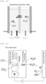
- FIG. 27 is a view schematically illustrating the configuration of such an electrolyzer.
- the tungsten oxide of the present invention is supported.
- the cathodic electrode and the carbon dioxide reduction catalyst on the cathodic electrode surface as well as the anion exchange membrane constitute a composite cathodic electrode.
- the gas diffusion layer is arranged on the opposite side of the cathodic electrode, to a side facing the anodic electrode, and carbon dioxide reaches the cathodic electrode and the catalyst on the cathodic electrode through this gas diffusion layer and is reduced to carbon monoxide.
- a KOH aqueous solution is supplied to the anodic electrode chamber and generates oxygen in the vicinity of the anodic electrode.
- the composite cathodic electrode also serves as the cathodic electrode chamber.
- the electrolyzer of the present invention can undergo alkaline water CO 2 electrolysis, in which carbon dioxide is reduced by electrolysis while alkaline water is electrolyzed.
- yet another embodiment of the electrolyzer of the present invention may comprise, on the opposite side of the cathodic electrode chamber, to a side facing the anodic electrode chamber, a carbon dioxide introduction part that introduces carbon dioxide so as to contact the cathodic electrode, and carbon dioxide may be reduced in the carbon dioxide introduction part.
- Figure 28 is a view schematically illustrating the configuration of such an electrolyzer.
- the anodic electrode chamber is arranged on the left hand side of the separating membrane and the cathodic electrode chamber is arranged on the right hand side.
- the carbon dioxide introduction part is arranged on the right hand side of the cathodic electrode chamber, i.e., on the opposite side of the cathodic electrode chamber, to a side facing the anodic electrode chamber. Carbon dioxide introduced here comes into contact with the cathode and is reduced to carbon monoxide.
- the carbon dioxide introduction part is not particularly limited as long as carbon dioxide can be introduced so that the cathode contacts the carbon dioxide, and examples of the carbon dioxide introduction part include a structure with a passage through which carbon dioxide flows and a structure in which a gas diffusion layer is arranged.
- Water comprising NaCl and NaOH is supplied to the anodic electrode chamber, and water comprising NaCl is supplied to the cathodic electrode chamber, to thereby generate oxygen in the vicinity of the anode supporting the tungsten oxide of the present invention and generate hydrogen in the vicinity of the cathode.
- the electrolyzer of the present invention enables alkaline salt water CO 2 electrolysis, in which carbon dioxide is reduced by electrolysis while alkaline salt water is electrolyzed.
- the electrolyzers in Figures 27 and 28 and the electrolysis method using these electrolyzers utilize the excellent activity of the tungsten oxide catalyst of the present invention for oxygen evolution reaction, allowing the activity of the entire reaction system to be enhanced by the driving force from the oxygen evolution reaction to activate the carbon dioxide reduction reaction.
- the method for reducing carbon dioxide to carbon monoxide has been exemplified as one example, but the present invention is not limited thereto.
- other substances produced by the reduction of carbon dioxide include carbon compounds such as formic acid (HCOOH), methane (CH 4 ), methanol (CH 3 OH), ethane (C 2 H 6 ), ethylene (C 2 H 4 ), ethanol (C 2 H 5 OH), formaldehyde (HCHO), acetaldehyde (CH 3 CHO), acetic acid (CH 3 COOH), ethylene glycol (HOCH 2 CH 2 OH), and 1-propanol (CH 3 CH 2 CH 2 OH).
- This solution was refluxed at 220°C for 1 hour under strong stirring. After the reflux, the solution was cooled naturally to room temperature. To the resulting mixed solution were added acetic acid and ethanol, and the mixture underwent centrifugation several times, then only distilled water was added, and the mixture underwent centrifugation several times. The residue was vacuum dried at room temperature for 5 hours to obtain tungsten oxide (p-Ni 0.5 Fe 0.5 WO 4 ) incorporating nickel and iron at a ratio of 5:5.
- Tungsten oxide (p-Ni 0.2 Fe 0.8 WO 4 ) incorporating nickel and iron at a ratio of 2:8 was obtained by the same method as in Example 1, except that the amount of nickel (II) acetate tetrahydrate added was 0.25 g and the amount of iron(II) acetate added was 0.70 g.
- Tungsten oxide (p-Ni 0.8 Fe 0.2 WO 4 ) incorporating nickel and iron at a ratio of 8:2 was obtained by the same method as in Example 1, except that the amount of nickel (II) acetate tetrahydrate added was 1.0 g and the amount of iron(II) acetate added was 0.18 g.
- the solution in the beaker was transferred to a Teflon(R) vessel and heated in an autoclave at 180°C for 24 hours. After the heating, the solution was cooled naturally to room temperature. To the resulting mixed solution, ethanol was added, and the mixture underwent centrifugation several times, then only distilled water was added, and the mixture underwent centrifugation several times. The residue was vacuum dried at 60°C for 12 hours to obtain tungsten oxide (h-Ni 0.5 Fe 0.5 WO 4 ) incorporating nickel and iron at a ratio of 5:5.
- WO 3 (purity: 95.0%, Wako Pure Chemical Industries, Ltd.) was prepared and used as a sample for Comparative Example 3.
- RuO 2 (purity: 99.9%, Sigma-Aldrich Co. LLC) was used as a sample for Comparative Example 4.
- IrO 2 (purity: 99% (99.9+%-Ir), Strem Chemicals, Inc.) was used as a sample for Comparative Example 5.
- XRD patterns were obtained by an X-ray diffractometer (Rigaku Ultima 4) equipped with CuK ⁇ radiation (40kv, 40mA).
- a mixed solution comprising 350 ⁇ L of ethanol, 350 ⁇ L of water, and 95 ⁇ L of Nafion were added 5 mg of each sample and 5 mg of acetylene carbon black (conductive carbon), and the mixture underwent ultrasonic dispersion treatment for 60 minutes. 10 ⁇ L of the resulting dispersion was added dropwise to a disk electrode (5 mm in diameter) polished with alumina (amount of active material: 0.32 mg). The disk electrode was then dried at room temperature in air and used as a working electrode. A three-electrode cell was used, with a platinum mesh as a counter electrode and a Hg/HgO electrode (1M NaOH) as a reference electrode.
- a mixed solution comprising 350 ⁇ L of ethanol, 350 ⁇ L of water, and 95 ⁇ L of Nafion were added 5 mg of each sample and 5 mg of acetylene carbon black (conductive carbon), and the mixture underwent ultrasonic dispersion treatment for 60 minutes. 10 ⁇ L of the resulting dispersion was added dropwise to a disk electrode (5 mm in diameter) polished with alumina (amount of active material: 0.32 mg). The disk electrode was then dried at room temperature in air and used as a working electrode. A three-electrode cell was used, with a platinum mesh as a counter electrode and Hg/HgO as a reference electrode. 1M KOH purged with N 2 for 30 minutes was used as an electrolytic solution. The constant current density of 10 mA/cm 2 was maintained for 24 hours. The working electrode was rotated at 1600 rpm as in linear sweep voltammetry.
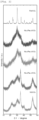
- Ni 0.5 Fe 0.5 WO 4 in Figure 1 denotes the XRD pattern of the sample obtained in Example 1
- Ni 0.5 Fe 0.5 WO 4 cal denotes the XRD pattern after heating the sample obtained in Example 1 at 600°C for 3 hours in air.
- NiWO 4 in Figure 1 denotes the XRD pattern of the sample obtained in Comparative Example 2
- NiWO 4 cal denotes the XRD pattern after heating the sample obtained in Comparative Example 2 at 600°C for 3 hours.
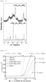
- Figure 3 shows the linear sweep voltammograms of the samples obtained in Examples 1 to 3 and Comparative Examples 1 to 4. As is clear from Figure 3 , the samples obtained in Examples 1 to 3 exhibited the sharp rise in current and had much higher catalytic activity than RuO 2 having the best catalytic performance for oxygen evolution reaction.
- Figure 5 shows the XRD patterns of the sample obtained in Example 4.
- h-Ni 0.5 Fe 0.5 WO 4 in Figure 5 is the XRD pattern of the sample obtained in Example 4
- h-Ni 0.5 Fe 0.5 WO 4 cal is the XRD pattern after heating the sample obtained in Example 4 at 600°C for 3 hours.
- the "h-" is a symbol indicating the sample obtained by the hydrothermal synthesis method.
- the "p-" symbol is added in order to indicate that they were obtained by the polyol method.
- Figure 5 shows that the sample obtained in Example 4 also has a crystal structure typical of wolframite after being heated at 600°C, and therefore it can be deemed that the obtained sample is a wolframite precursor, or is low-crystalline wolframite having the same composition, i.e., having the same composition as wolframite and is in the undeveloped crystalline state.
- Linear sweep voltammograms of the samples obtained in Examples 1 and 4 and Comparative Examples 1, 2, and 4 are shown in Figure 6 .
- Example 1 the samples obtained in Examples 1 and 4 exhibited the sharp rise in current, low overpotential required for reaching 10 mA/cm 2 or 100 mA/cm 2 , and much higher catalytic activity than RuO 2 having the best catalytic performance for oxygen evolution.
- the sample in Example 1, synthesized by the polyol method exhibited the sharper rise than the sample in Example 4, synthesized by the hydrothermal synthesis method.
- Tafel plots were created in order to analyze the rising portions in Figures 3 and 6 .
- Figure 4 shows the plots obtained by plotting common logarithms of the current densities in Figure 3 on the abscissa and the differences (overpotential) from the standard potential of 1.23 V for water oxidation on the ordinate.
- Figure 7 also shows similar plots for Figure 6 .
- the parameters calculated from Figures 3 and 4 as well as Figures 6 and 7 starting overpotential is defined as the endpoint on the low-potential side of the linear region in Figure 4 or Figure 7 ) are shown in Table 1.
- the samples obtained in Examples 1 to 4 exhibit the starting overpotential comparable to that of RuO 2 (Comparative Example 4), and the overpotential at a current density of 10 mA/cm 2 is lower than that of the RuO 2 (Comparative Example 4) sample. Furthermore, the Tafel slope is also smaller than that of the RuO 2 (Comparative Example 4) sample.
- the Tafel slope is a potential difference required for increasing a current value by a factor of 10; a smaller value indicates faster reaction rate and more active reaction, and also indicates fast electron transfer in water oxidation.
- Table 1 demonstrates the results that the samples obtained in Examples 1 to 4 have extremely faster reaction rates than RuO 2 (Comparative Example 4) and the samples obtained in other Comparative Examples.
- Figure 8 is a view illustrating the overpotential of Examples 1 to 3 and Comparative Examples 1 and 2 at a current density of 10 mA/cm 2 , indicating that the overpotential is significantly lowered when nickel and iron are incorporated compared to when nickel is singly incorporated or when iron is singly incorporated.
- Figure 9 is a view where only the results of Examples 1 to 3 and Comparative Examples 1 and 2 are extracted from the linear sweep voltammograms in Figure 3 .
- Example 1 (p-Ni 0.5 Fe 0.5 WO 4 ) 30.8 247 297
- Example 2 (p-Ni 0.5 Fe 0.8 WO 4 ) 30.6 248 314
- Example 3 (p-Ni 0.8 Fe 0.2 WO 4 ) 40.4 250 333
- a reaction surface area (electrochemically active surface area: ECSA) of each of the samples obtained in Examples 1 to 4 and Comparative Examples 1, 2, and 6 was determined.
- ECSA electrochemically active surface area
- an electrochemical double layer capacitance (Cdl) which is proportional to ECSA, was calculated for each sample by cyclic voltammetry (CV).
- Figure 10 shows the results of CV measurement for the sample obtained in Example 4.
- the CV potential range was 0 to 0.1 V, the range in which the Faraday reaction was not observed.
- Cdl was calculated from the plot of the relationship between the difference ⁇ j between the cathodic current and the anodic current at a specific potential for each sample (0.05 V vs Hg/HgO) and the sweep rate ( Figure 11 ).
- the magnitude of the current obtained by using the catalyst is considered to be determined by multiplication of (i) the intrinsic reaction rate at an active site and (ii) the quantity of active sites (i.e., the size of area electrochemically utilized). Since (i) is reflected on the Tafel slope and (ii) on ECSA, a large ECSA enhances catalytic activity. Moreover, the catalysts obtained in Examples 1 to 3 have smaller ECSA than others, but have excellent catalytic activity due to the smaller Tafel slope and faster intrinsic reaction rate.
- TOF Turnover frequency
- Example 1 (p-Ni 0.5 Fe 0.5 WO 4 ) 0.425
- Example 2 (p-Ni 0.2 Fe 0.8 WO 4 ) 0.238
- Example 3 (p-Ni 0.8 Fe 0.2 WO 4 ) 0.106
- Example 4 (h-Ni 0.5 Fe 0.5 WO 4 ) 0.072 Comparative Example 1 (FeWO 4 ) 0.001 Comparative Example 2 (NiWO 4 ) 0.020 Comparative Example 6 (p-NiFe oxide) 0.057
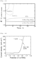
- Figure 13 shows the results of durability tests on p-Ni 0.5 Fe 0.5 WO 4 obtained in Example 1, h-Ni 0.5 Fe 0.5 WO 4 obtained in Example 4, FeWO 4 obtained in Comparative Example 1, NiWO 4 obtained in Comparative Example 2, and IrO 2 (99% (99.9+%-Ir), manufactured by Strem Chemicals, Inc.) in Comparative Example 5.
- FeWO 4 had a rapid increase in potential with an elapsed time of about 3 hours after starting the test.
- delamination of the catalyst film from the substrate was observed. This phenomenon is considered to be due to oxidation to FeO 4 2- at high potential and dissolution.
- NiWO 4 increased its potential with an elapsed time of about 4.5 hours after starting the test, and rapidly increased the potential with an elapsed time of about 6 hours.
- the visual observation of the catalyst film confirmed that oxygen bubbles adhered to the catalyst surface and the catalyst film was partially delaminated from the substrate with an elapsed time of about 4.5 hours, and then further delamination of the catalyst film was observed with an elapsed time of about 6 hours. This suggests that the catalyst film was physically destroyed by generation of oxygen bubbles on the catalyst surface.
- IrO 2 increased the overpotential by nearly 1.0 V from the initial potential in 24 hours. It is deemed that this is because the diffusion resistance between the reactant (H 2 O) and the product (O 2 ) was raised.
- tungsten oxide of the present invention thus has excellent durability as a catalyst.
- Figure 14 shows the results of the cycle test carried out at 20 mVs -1 by using the three-electrode cell using the working electrode fabricated with p-Ni 0.5 Fe 0.5 WO 4 , fabricated in Example 1, the platinum mesh as a counter electrode, and a Hg/HgO electrode as a reference electrode, and using 1M KOH purged with N 2 for 30 minutes as an electrolytic solution, as in the durability test described above.
- the current response changed little between the first cycle and after 400 cycles. It is also suggested that the physical break of the catalyst film was inhibited by the rapid diffusion of the oxygen produced.
- Table 4 shows the potential at 10 mA/cm 2 in LSV and the holding potential at 10 mA/cm 2 in CP for p-Ni 0.5 Fe 0.5 WO 4 , h-Ni 0.5 Fe 0.5 WO 4 , and IrO 2 used in the durability test.
- Catalyst Potential at 10mA/cm 2 in LSV V
- Holding potential at 10mA/cm 2 in CP V
- the XRD patterns, linear sweep voltammograms, and Tafel plots of p-Ni 0.5 Fe 0.5 WO 4 fabricated in Example 1, the sample obtained by heating this at 600°C for 3 hours, and p-NiFe oxide fabricated in Comparative Example 6 are shown in Figures 15, 16 , and 17 , respectively.
- the sample obtained by heating p-Ni 0.5 Fe 0.5 WO 4 at 600°C for 3 hours (p-Ni 0.5 Fe 0.5 WO 4 cal) had a wolframite phase, while the sample without heating had an undeveloped wolframite phase.
- p-NiFe oxide had a trevolite phase and was assigned to Ni 1.43 Fe 1.7 O 4 according to the Rigaku database.
- the sample obtained by heating p-Ni 0.5 Fe 0.5 WO 4 fabricated in Example 1 at 600°C for 3 hours did not have such high catalytic activity for oxygen evolution.
- the XRD patterns, linear sweep voltammograms, and Tafel plots of p-Ni 0.5 Fe 0.5 WO 4 fabricated in Example 1, and the samples obtained by heating this at 300°C for 3 hours, at 450°C for 3 hours, and at 600°C for 3 hours are shown in Figures 18 , 19, and 20 , respectively.
- the samples heated at 300°C and at 450°C exhibited the sharp rise in current and had excellent catalytic activity for oxygen evolution.
- the crystallite size of each sample was calculated by using the Scherrer equation below.
- the crystallite size of p-Ni 0.5 Fe 0.5 WO 4 without heating was 5.0 nm
- the crystallite size of that heat-treated at 300°C was 6.4 nm
- the crystallite size of that heat-treated at 450°C was 13.0 nm
- the crystallite size of that heat-treated at 600°C was 16.8 nm.
- the tungsten oxide of the present invention is preferably low-crystalline wolframite or a wolframite precursor that becomes wolframite upon heat treatment.
- the electrolytic solutions used were a 0.5 M NaCl aqueous solution, an aqueous solution comprising 0.5 M NaCl and 0.1 M NaOH (+0.1 M NaOH), an aqueous solution comprising 0.5 M NaCl and 0.5 M NaOH (+0.5 M NaOH), an aqueous solution comprising 0.5 M NaCl and 1.0 M NaOH (+1.0 M NaOH), and an aqueous solution comprising 0.5 M NaCl and a 0.1 M borate buffer.
- 1 M KOH purged with N 2 for 30 minutes was used.
- the sweep rate was set at 1 mV/s, and the rotation speed was set at 1600 rpm to remove oxygen bubbles on the working electrode.
- Example 5 The same operations and treatments as in Example 5 were carried out except that the electrolytic solutions used were a 0.5 M NaClO 4 aqueous solution, an aqueous solution comprising 0.5 M NaClO 4 and 0.1 M NaOH (+0.1 M NaOH), an aqueous solution comprising 0.5 M NaClO 4 and 0.5 M NaOH (+0.5 M NaOH), an aqueous solution comprising 0.5 M NaClO 4 and 1.0 M NaOH (+1.0 M NaOH), and an aqueous solution comprising 0.5 M NaClO 4 and a 0.1 M borate buffer in Example 5.
- the linear sweep voltammetry (LSV) obtained is shown in Figure 22 . Note that the descriptions in the parentheses following the descriptions of the aqueous solutions above indicate the notations in Figure 22 .
- Example 5 the Tafel slope and the overpotential ( ⁇ ) at 10 mA/cm 2 were investigated.
- the pH of the 0.5 M NaCl aqueous solution in Example 5 was 5, the pH of the aqueous solution comprising 0.5 M NaCl and 0.1 M NaOH was 13, the pH of the aqueous solution comprising 0.5 M NaCl and 0.5 M NaOH was 13.5, the pH of the aqueous solution comprising 0.5 M NaCl and 1.0 M NaOH was 14, and the pH of the aqueous solution comprising 0.5 M NaCl and a 0.1 M borate buffer was 9.
- the pH of the 0.5 M NaClO 4 aqueous solution in Example 6 was 5, the pH of the aqueous solution comprising 0.5 M NaClO 4 and 0.1 M NaOH was 13, the pH of the aqueous solution comprising 0.5 M NaClO 4 and 0.5 M NaOH was 13.5, the pH of the aqueous solution comprising 0.5 M NaClO 4 and 1.0 M NaOH was 14, and the pH of the aqueous solution comprising 0.5 M NaClO 4 and a 0.1 M borate buffer was 9.
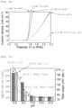
- the Tafel slope at each pH and the overpotential ( ⁇ ) at 10 mA/cm 2 is shown in Figure 23 .
- Example 5 The same operations and treatments as in Example 5 were carried out except that IrO 2 of Comparative Example 5 was used instead of p-Ni 0.5 Fe 0.5 WO 4 in Example 5.
- the linear sweep voltammetry (LSV) obtained is shown in Figure 24 .
- Example 6 The same operations and treatments as in Example 6 were carried out except that IrO 2 of Comparative Example 5 was used instead of p-Ni 0.5 Fe 0.5 WO 4 in Example 6.
- the linear sweep voltammetry (LSV) obtained is shown in Figure 25 .
- the 0.5 M NaCl aqueous solution in Example 5 is an aqueous solution that mimics seawater.
- Figure 21 for Example 5 demonstrates that the tungsten oxide of the present invention exhibited the sharp rise in current and had high catalytic activity for oxygen evolution by adding alkali to the 0.5 M NaCl aqueous solution. Therefore, the tungsten oxide of the present invention is excellent as a catalyst for oxygen evolution reaction for alkaline seawater electrolysis.
- the electrolyzer with the tungsten oxide of the present invention supported on the anodic electrode as a catalyst is excellent as an electrolyzer for hydrogen evolution by alkaline seawater electrolysis because the oxygen evolution reaction at the anodic electrode is enhanced, thereby enhancing the hydrogen evolution reaction at the cathodic electrode as well.
- the IrO 2 electrode used in Comparative Example 7 was also used to measure the residual chlorine concentration in the test solution after electrolysis by using the same test method and measurement method as for the p-Ni 0.5 Fe 0.5 WO 4 electrode described above. It is found from the results that the chlorine generation efficiency was 47% for the 0.5 M NaCl aqueous solution, 0.6% for the aqueous solution comprising 0.5 M NaCl and 0.1 M NaOH, 0.5% for the aqueous solution comprising 0.5 M NaCl and 0.5 M NaOH, 0.1% for the aqueous solution comprising 0.5 M NaCl and 1.0 M NaOH, and 0.6% for the aqueous solution comprising 0.5 M NaCl and a 0.1 M borate buffer. These results indicate that the use of the tungsten oxide of the present invention as a catalyst can inhibit generation of chlorine species upon oxygen evolution more than the use of IrO 2 , which is conventionally used as a catalyst exhibiting high activity for the oxygen evolution reaction.
- Figure 23 also shows that the tungsten oxide of the present invention, when used as a catalyst, has high oxygen evolution reaction activity at a pH of 9 or greater, 10 or greater, 11 or greater, 12 or greater, or 13 or greater.
- Comparative Examples 7 and 8 are examples in which IrO 2 conventionally used as a catalyst exhibiting high activity for the oxygen evolution reaction was used, and the results are shown in Figures 24 and 25 .
- the tungsten oxide of the present invention can be suitably used as a catalyst for oxygen evolution reaction in electrolysis, batteries, and the like, and, for example, it can be used as an anodic electrode in water electrolysis, an air electrode (positive electrode) in metal-air batteries, and a counter electrode for reduction reaction in electrolysis of carbon dioxide.
- the tungsten oxide of the present invention can be used as catalysts for electrolysis such as alkaline water electrolysis, alkaline seawater (salt water) electrolysis, alkaline CO 2 electrolysis, and alkaline CO 2 seawater (salt water) electrolysis.
- the electrolyzer of the present invention comprises the tungsten oxide of the invention as a catalyst, it can be suitably used as electrolyzers in various electrolysis such as water electrolysis, and for example, it can be suitably used as electrolyzers for electrolysis such as alkaline water electrolysis, alkaline seawater (salt water) electrolysis, alkaline CO 2 electrolysis, and alkaline CO 2 seawater (salt water) electrolysis.
- the production method of the present invention is suitable as a method for producing such tungsten oxides.
Landscapes
- Chemical & Material Sciences (AREA)
- Organic Chemistry (AREA)
- Materials Engineering (AREA)
- Engineering & Computer Science (AREA)
- Chemical Kinetics & Catalysis (AREA)
- Electrochemistry (AREA)
- Metallurgy (AREA)
- Inorganic Chemistry (AREA)
- Physics & Mathematics (AREA)
- Thermal Sciences (AREA)
- Catalysts (AREA)
- Oxygen, Ozone, And Oxides In General (AREA)
- Inorganic Compounds Of Heavy Metals (AREA)
- Organic Low-Molecular-Weight Compounds And Preparation Thereof (AREA)
Abstract
Description
- The present invention relates to tungsten oxide represented by NixFe1-xWO4 (wherein 0 < x < 1), a catalyst for oxygen evolution reaction comprising the tungsten oxide, and a method for producing the tungsten oxide.
- In recent years, methods for producing hydrogen utilizing renewable energy have been attracting attention in order to solve problems such as global warming due to a greenhouse effect of carbon dioxide. The production of hydrogen utilizing renewable energy is required to lower cost so that it is comparable to that of the conventional method for producing hydrogen by reforming fossil fuels. Hydrogen production methods that can meet this requirement include electrolysis of water. A representative method of water electrolysis is alkaline water electrolysis. A power loss occurs upon the alkaline water electrolysis, and the main factors of the power loss include overpotential of an anodic electrode, overpotential of a cathodic electrode, an ohmic loss of an ion-permeable separating membrane, and an ohmic loss due to structural resistance of an electrolytic cell unit. If it is capable of reducing these power losses, the entire system can be miniaturized by enhancing a current density upon electrolysis in an electrolyzer, resulting in enabling significant reduction of equipment cost. Therefore, development of a catalyst capable of reducing the power losses has been desired.
- Conventionally, ruthenium oxide, iridium oxide, and the like have been used as catalysts for oxygen evolution reaction, but these catalysts use precious metals, which are costly and limited resources. Therefore, utilization of tungsten oxide consisting of tungsten that is less costly and has more plentiful resources than precious metals, as a catalyst for the oxygen evolution reaction, has been investigated.
Non-patent Document 1 describes Co1-xFexWO4-CNT, a composite of Co1-xFexWO4 and carbon nanotubes (CNTs), which is used as an oxygen evolution reaction (OER) catalyst. However, the document reports that the composite lowers its overpotential by being composited with carbon nanotubes, whereas overpotential of Co0.5Fe0.5WO4 without being composited with the carbon nanotubes is higher, with a value of 420 mV. Moreover,Non-patent Document 2 reports use of Ni-Fe-W hydroxide as a catalyst for OER, and it is also composited with carbon fibers. Therefore, there has been demand for a compound that exhibits high catalytic activity without using precious metals such as ruthenium and iridium. -
- Non-patent Document 1: Composite Metal Oxide-Carbon Nanotube Electrocatalysts for the Oxygen Evolution and Oxygen Reduction Reactions, ChemElectroChem, 5, 2850-2856(2018)
- Non-patent Document 2: Jie Xu, Mingshuo Wang, FeiYang, Xiaoqian Ju, Xilai Jia, "Self-Supported Porous Ni-Fe-W Hydroxide Nanosheets on Carbon Fiber: A Highly Efficient Electrode for Oxygen Evolution Reaction", Inorg. Chem. 58, 13037-13048 (2019).
- An object of the present invention is to provide a compound with high catalytic activity that can be used as a catalyst for oxygen evolution reaction.
- The present inventors investigated a new compound with high catalytic activity that can be used as a catalyst for oxygen evolution reaction and have found that the compound represented by NixFe1-xWO4 (wherein 0 < x < 1) has very high catalytic activity. Although there was conventionally a literature describing use of various metal elements as M in the compound represented by MWO4, a compound in which M was a combination of Ni and Fe, by which very high catalytic activity could be obtained, was not known.
- Namely, the present invention can be identified according to the items described below:
- (1) Tungsten oxide represented by NixFe1-xWO4 (wherein 0 < x < 1) .
- (2) A catalyst for oxygen evolution reaction for use in an anodic electrode or a positive electrode, comprising the tungsten oxide according to (1) above.
- (3) A method for producing tungsten oxide represented by NixFe1-xWO4 (wherein 0 < x < 1), wherein a tungstate salt, a nickel salt, and an iron salt are dissolved in a polyol, and a polyol solution in which the salts are dissolved is heated to synthesize the tungsten oxide, or wherein a tungstate salt, a nickel salt, an iron salt, and water are added into a pressure-resistant vessel and heated to synthesize the tungsten oxide.
- (4) An electrolyzer comprising an anodic electrode chamber and a cathodic electrode chamber divided by an ion-permeable separating membrane, wherein an anodic electrode is arranged in the anodic electrode chamber and a cathodic electrode is arranged in the cathodic electrode chamber, and wherein tungsten oxide represented by NixFe1-xWO4 (wherein 0 < x < 1) is supported on the anodic electrode as a catalyst.
- (5) The electrolyzer according to (4) above, comprising a gas diffusion layer for supplying carbon dioxide to the cathodic electrode, wherein the carbon dioxide is reduced in the cathodic electrode chamber.
- (6) The electrolyzer according to (4) above, comprising, on an opposite side of the cathodic electrode chamber, to a side facing the anodic electrode chamber, a carbon dioxide introduction part that introduces carbon dioxide so as to contact the cathodic electrode, wherein the carbon dioxide is reduced in the carbon dioxide introduction part.
- (7) A method for electrolyzing salt water, wherein, in the electrolyzer according to (4) above, salt water comprising alkali is supplied to the anodic electrode chamber and salt water is supplied to the cathodic electrode chamber to electrolyze the salt water.
- (8) A method for electrolyzing salt water as well as reducing carbon dioxide, wherein, in the electrolyzer according to (6) above, salt water comprising alkali is supplied to the anodic electrode chamber, salt water is supplied to the cathodic electrode chamber, and carbon dioxide is introduced into the carbon dioxide introduction part to electrolyze the salt water as well as reduce the carbon dioxide.
- The tungsten oxide of the present invention exhibits excellent catalytic activity when used as a catalyst for oxygen evolution reaction. The catalyst for oxygen evolution reaction of the present invention exhibits excellent catalytic activity by comprising the tungsten oxide of the present invention. The production method of the present invention can produce the tungsten oxide of the present invention.
-
- [
Figure 1] Figure 1 is a view illustrating the XRD patterns of the samples obtained in Example 1 and Comparative Example 2. - [
Figure 2] Figure 2 is a view illustrating the XRD patterns of the samples obtained in Examples 1 to 3 and Comparative Examples 1 and 2. - [
Figure 3] Figure 3 is a view illustrating the linear sweep voltammograms of the samples obtained in Examples 1 to 3 and Comparative Examples 1 to 4. - [
Figure 4] Figure 4 is a view illustrating the Tafel plots of the samples obtained in Examples 1 to 3 and Comparative Examples 1 to 4. - [
Figure 5] Figure 5 is a view illustrating the XRD patterns of the sample obtained in Example 4. - [
Figure 6] Figure 6 is a view illustrating the linear sweep voltammograms of the samples obtained in Examples 1 and 4 and Comparative Examples 1, 2, and 4. - [
Figure 7] Figure 7 is a view illustrating the Tafel plots of the samples obtained in Examples 1 and 4 and Comparative Examples 1, 2, and 4. - [
Figure 8] Figure 8 is a view illustrating the overpotential at a current density of 10 mA/cm2 for Examples 1 to 3 and Comparative Examples 1 and 2. - [
Figure 9] Figure 9 is a view illustrating the linear sweep voltammograms of Examples 1 to 3 and Comparative Examples 1 and 2. - [
Figure 10] Figure 10 is a view illustrating the results of CV measurements of the sample obtained in Example 4. - [
Figure 11] Figure 11 is a view plotting the relationship between the difference Δj between a cathode current and an anode current and the sweep rate at a potential of 0.05 V vs Hg/HgO for each sample. - [
Figure 12] Figure 12 is a view illustrating changes in turnover frequency when overpotential was changed. - [
Figure 13] Figure 13 is a view illustrating the relationship between an elapsed time and potential in a durability test. - [
Figure 14] Figure 14 is a view illustrating the results of a cycle test. - [
Figure 15] Figure 15 is a view illustrating the XRD patterns of the samples obtained in Example 1 and Comparative Example 6, as well as that obtained by heating the sample obtained in Example 1 at 600°C. - [
Figure 16] Figure 16 is a view illustrating the linear sweep voltammograms of the samples obtained in Example 1 and Comparative Example 6, as well as that obtained by heating the sample obtained in Example 1 at 600°C. - [
Figure 17] Figure 17 is a view illustrating the Tafel plots of the samples obtained in Example 1 and Comparative Example 6, as well as that obtained by heating the sample obtained in Example 1 at 600°C. - [
Figure 18] Figure 18 is a view illustrating the XRD patterns of samples obtained by heating the sample obtained in Example 1 at various temperatures. - [
Figure 19] Figure 19 is a view illustrating the linear sweep voltammograms of samples obtained by heating the sample obtained in Example 1 at various temperatures. - [
Figure 20] Figure 20 is a view illustrating the Tafel plots of samples obtained by heating the sample obtained in Example 1 at various temperatures. - [
Figure 21] Figure 21 is a view illustrating the linear sweep voltammograms in Example 5. - [
Figure 22] Figure 22 is a view illustrating the linear sweep voltammograms in Example 6. - [
Figure 23] Figure 23 is a view illustrating the Tafel slopes and overpotential at 10 mA/cm2 when pH was varied. - [
Figure 24] Figure 24 is a view illustrating the linear sweep voltammograms in Comparative Example 7. - [
Figure 25] Figure 25 is a view illustrating the linear sweep voltammograms in Comparative Example 8. - [
Figure 26] Figure 26 is a schematic view illustrating one embodiment of the electrolyzer of the present invention. - [
Figure 27] Figure 27 is a schematic view illustrating one embodiment of the electrolyzer of the present invention. - [
Figure 28] Figure 28 is a schematic view illustrating one embodiment of the electrolyzer of the present invention. - The tungsten oxide of the present invention is the compound represented by the chemical formula NixFe1-xWO4 (wherein 0 < x < 1). x is preferably 0.05 or more and 0.95 or less, preferably 0.10 or more and 0.90 or less, preferably 0.15 or more and 0.85 or less, preferably 0.2 or more and 0.8 or less, and more preferably 0.4 or more and 0.6 or less. Conventionally, ruthenium oxide, iridium oxide, and the like have been used as catalysts for oxygen evolution reaction, but the tungsten oxide of the present invention is superior in cost because it has a catalytic effect on oxygen evolution reaction without using precious metals such as ruthenium and iridium. Moreover, these metals have a problem of toxicity, whereas tungsten oxide has no toxicity problem. Furthermore, the tungsten oxide of the present invention is superior in catalytic activity than the case of using the precious metals. Conventionally, Co1-xFexWO4 (wherein 0 < x < 1), which is wolframite-type tungsten oxide comprising cobalt and iron, has been known as tungsten oxide with catalytic activity for oxygen evolution reaction, but the tungsten oxide represented by NixFe1-xWO4 (wherein 0 < x < 1), was not known. Known catalysts for oxygen evolution reaction consisting of nickel, iron, and tungsten are hydroxides and are different from the tungsten oxide of the present invention. The present invention is such that the tungsten oxide represented by NixFe1-xWO4 (wherein 0 < x < 1) was synthesized and found to be excellent as a catalyst for oxygen evolution reaction for one of the applications of the compound. The tungsten oxide of the present invention is preferably low-crystalline wolframite or a wolframite precursor that becomes wolframite upon heat treatment. Suitable crystallite sizes of the tungsten oxide of the present invention include 2.0 nm to 15.0 nm, 2.0 nm to 14.0 nm, 3.0 nm to 14.0 nm, or 3.0 nm to 7.0 nm.
- The catalyst for oxygen evolution reaction of the present invention comprises the tungsten oxide of the present invention represented by NixFe1-xWO4 (wherein 0 < x < 1). The catalyst for oxygen evolution reaction of the present invention may consist only of the tungsten oxide of the present invention, or may comprise other compounds as long as it has catalytic activity, or may also be supported on a substrate such as a nickel foam, a carbon material, or a metal plate. The catalyst for oxygen evolution reaction of the present invention can be used for an anodic electrode or a positive electrode, for example, as a catalyst for oxygen evolution reaction in electrolysis, batteries, and the like, and for example, it can be used for an anodic electrode in water electrolysis, an air electrode (positive electrode) in metal-air batteries, and a counter electrode for reduction reaction in electrolysis of carbon dioxide. The tungsten oxide of the present invention used as a catalyst for oxygen evolution reaction can be a catalyst for oxygen evolution reaction with overpotential of 250 to 400 mV, 250 to 350 mV, or 300 to 350 mV to reach a current density of 10 mA/cm2. The tungsten oxide of the present invention can also be a catalyst for oxygen evolution reaction with a Tafel slope in the range of 30 to 50 mVdec-1, 30 to 45 mVdec-1, or 30 to 40 mVdec-1. In addition, the tungsten oxide of the present invention can be a catalyst for oxygen evolution reaction with an electrochemically active surface area in the range of 5 to 20 m2/g or 5 to 15 m2/g.
- The method for producing the tungsten oxide of the present invention is not particularly limited, and examples thereof include a polyol method and a hydrothermal synthesis method. The polyol method is a method for dissolving a raw material salt in a polyol followed by heating the mixture to obtain a target product, and the hydrothermal synthesis method is a method for adding raw materials and water in a pressure-resistant sealed vessel and heating the mixture while sealing the vessel to obtain a target product. The polyol method comprises a step of dissolving various raw materials in a polyol and heating the polyol solution obtained in the above step, and when the tungsten oxide of the present invention is produced by the polyol method, the polyol used is not particularly limited, and examples thereof include ethylene glycol, propylene glycol, tetraethylene glycol, trimethylene glycol, tetramethylene glycol, diethylene glycol, dipropylene glycol, and polyethylene glycol. The salt to be dissolved in the polyol is salt comprising at least one of nickel, iron, and tungsten, which are the constituents of the tungsten oxide of the present invention, and is not particularly limited as long as it dissolves in the polyol for use, and these salts are used in combination and dissolved, so that the above three components are comprised in the polyol. Examples of tungsten sources include a tungstate salt. The tungstate salts include sodium tungstate, ammonium tungstate, and calcium tungstate. Nickel sources and iron sources include an acetate, a sulfate, a nitrate, and chloride of these sources. The heating temperature in the polyol method is not particularly limited, but is preferably a temperature in the vicinity of, or not higher than the boiling point of the polyol used as a solvent. The heating method is also not particularly limited, but is preferably refluxing at a temperature in the vicinity of the boiling point of the polyol used, since the most amount of heat can be applied at a normal pressure upon carrying out the synthesis reaction. A heating time can be appropriately selected as a time sufficient for the synthesis reaction to take place. For example, salt comprising nickel, salt comprising iron, and salt comprising tungsten are dissolved in a polyol. At this time, water may be added as appropriate, and the pH may be adjusted, if necessary. This solution is heated and refluxed. The heating temperature at this time varies depending on the type of polyol used, the amount of water added to the polyol, and the like, but it may be a temperature at which the aforementioned solution can be refluxed. The heating time is not particularly limited as long as the synthesis reaction is sufficiently carried out, and examples thereof include 30 minutes to 3 hours or 30 minutes to 2 hours. After heating, the temperature of the above solution is lowered to room temperature, and the solids can be collected by separation operations such as centrifugation to obtain the synthesized tungsten oxide of the present invention. Using a polyol as a solvent is considered to allow the polyol to act as a protective agent for a surface of the tungsten oxide particles produced and to prevent catalyst particles from growing due to aggregation thereof, resulting in enabling tungsten oxide having low overpotential, a large electrochemically active surface area, and high catalytic activity when used as a catalyst for oxygen evolution reaction, to be obtained. Moreover, the polyol method can synthesize tungsten oxide in a polyol at a normal pressure, thereby making it possible to be less expensive than a hydrothermal synthesis method requiring a pressure-resistant vessel.
- In the case of producing the tungsten oxide of the present invention by the hydrothermal synthesis method, a raw material is not particularly limited as long as it is a substance dissolving in water at a predetermined temperature and pressure in a pressure-resistant vessel, and examples of tungsten sources include a tungstate salt. The tungstate salts include sodium tungstate, ammonium tungstate, and calcium tungstate. Examples of nickel sources and iron sources include respective salts thereof, which include an acetate, a sulfate, a nitrate, and a chloride. In the hydrothermal synthesis method, for example, a raw material for the tungsten source, a raw material for the nickel source, and a raw material for the iron source together with water are added into a pressure-resistant vessel and heated, and the mixture is reacted at a predetermined temperature and pressure for a predetermined time to enable production of tungsten oxide of the present invention. The temperature and pressure in the hydrothermal synthesis method can be appropriately selected according to the raw materials used, and examples of the temperature include 100 to 200°C, and the pressure in this case can be approximately 1 to 15 atmospheres. The synthesis time is not particularly limited as long as the synthesis reaction is sufficiently carried out, and examples of the synthesis time include 12 to 48 hours. Following the synthesis, the temperature and pressure in the pressure-resistant vessel are lowered, and the solids can be collected to obtain the tungsten oxide of the present invention.
- The electrolyzer of the present invention comprises an anodic electrode chamber and a cathodic electrode chamber divided by an ion-permeable separating membrane, wherein an anodic electrode is arranged in the anodic electrode chamber and a cathodic electrode is arranged in the cathodic electrode chamber, and wherein the tungsten oxide of the present invention represented by NixFe1-xWO4 (wherein 0 < x < 1) is supported on the anodic electrode as a catalyst. The ion-permeable separating membrane in the present invention is not particularly limited as long as it is an ion-permeable separating membrane that can be used in an electrolyzer for electrolysis of an aqueous solution and the like, and examples of the ion-permeable separating membrane include a porous membrane consisting of asbestos or modified asbestos, a porous separating membrane using a polysulfone-based polymer, a cloth using polyphenylene sulfide fibers, a fluorine-based porous membrane, a porous separating membrane such as a porous membrane using a hybrid material comprising both an inorganic material and an organic material, and an ion-exchange membrane such as a fluorine-based ion-exchange membrane. The ion-permeable separating membrane in the present invention preferably has low gas permeability, low electrical conductivity, and high strength. The anodic electrode in the present invention has the tungsten oxide of the present invention supported on a conductive substrate as a catalyst. The conductive substrate is not particularly limited as long as it is a substrate that can be used as an electrode for electrolysis, and examples of the conductive substrate include nickel, a nickel alloy, nickel iron, vanadium, molybdenum, copper, silver, manganese, platinum group elements, graphite, or chromium, or combinations thereof. The conductive substrate may be a rigid substrate or a flexible substrate. Examples of the rigid conductive substrate include an expanded metal and a punched metal, and examples of the flexible conductive substrate include a wire mesh woven (or knitted) with metal wire. The method for supporting the tungsten oxide of the present invention onto the conductive substrate and the amount loaded are not particularly limited as long as the tungsten oxide of the present invention can contact an electrolytic solution and act as a catalyst, and examples of the supporting method include a method for covering the entire or partial surface of the conductive substrate, or a method for adhering the tungsten oxide to the entire or partial surface of the conductive substrate. The cathodic electrode in the present invention is not particularly limited as long as it is a substrate that can be used as an electrode for electrolysis, but it usually comprises a conductive substrate and a catalytic layer supported on a surface of the substrate. The conductive substrate is not particularly limited as long as it is a substrate that can be used as an electrode for electrolysis, and examples of the conductive substrate include nickel, a nickel alloy, stainless steel, mild steel, or stainless steel or mild steel with nickel plating thereon. The conductive substrate may be, for example, a rigid substrate or a flexible substrate. Examples of the rigid conductive substrate include an expanded metal and a punched metal, and examples of the flexible conductive substrate include a wire mesh woven (or knitted) with metal wire. The catalytic layers of the cathodic electrode include a catalytic layer comprising of a precious metal or precious metal oxide, nickel, cobalt, molybdenum, or manganese, or oxides thereof. In the anodic electrode chamber and cathodic electrode chamber in the present invention, the aforementioned anodic electrode and cathodic electrode are arranged, respectively.
- In the electrolyzer of the present invention, water comprising an electrolyte is supplied to the anodic electrode chamber and cathodic electrode chamber and electrolyzed, to produce oxygen in the anodic electrode chamber, and produce hydrogen in the cathodic electrode chamber.
Figure 26 is a view schematically illustrating the configuration of the electrolyzer of the present invention. On the anode (anodic electrode), the tungsten oxide of the present invention is supported. The left hand side of the separating membrane is the anodic electrode chamber and the right hand side is the cathodic electrode chamber, and the anode (anodic electrode) is arranged in the anodic electrode chamber and the cathode (cathodic electrode) is arranged in the cathodic electrode chamber. InFigure 26 , the anode and cathode are arranged at the ends of the anodic electrode chamber and cathodic electrode chamber, respectively, but they may be arranged at positions other than the ends, such as in the vicinity of the center. The anodic electrode chamber is supplied with water comprising NaCl and KOH, and the cathodic electrode chamber is supplied with water comprising NaCl. The separating membrane is an anion-permeable membrane, and OH- moves from the cathodic electrode chamber to the anodic electrode chamber. Oxygen is produced in the vicinity of the anode, and hydrogen is produced in the vicinity of the cathode. With the electrolyzer of the present invention, salt water comprising alkali is supplied to the anodic electrode chamber, and salt water is supplied to the cathodic electrode chamber, allowing salt water to be electrolyzed. Here, the alkali refers to a compound that dissolves in water and exhibits basicity, and examples of the alkali include hydroxide of an alkali metal and hydroxide of an alkaline earth metal.Figure 26 shows an example in which KOH is used as alkali, but for example, NaOH, LiOH, and CsOH can be used in addition to KOH. Moreover, the salt water refers to an aqueous solution comprising NaCl. The electrolyzer of the present invention can also undergo alkaline water electrolysis, in which water comprising no NaCl but alkali is supplied to the anodic electrode chamber and cathodic electrode chamber, and the supplied water is electrolyzed, as well as can undergo alkaline salt water electrolysis, in which water comprising NaCl and alkali is supplied as described above, and the supplied water is electrolyzed. - Further, in addition to the anodic electrode chamber, separating membrane, and cathodic electrode chamber, another embodiment of the electrolyzer of the present invention may comprise a gas diffusion layer for supplying carbon dioxide to a cathodic electrode, and carbon dioxide may be reduced.
Figure 27 is a view schematically illustrating the configuration of such an electrolyzer. On the anodic electrode, the tungsten oxide of the present invention is supported. InFigure 27 , the cathodic electrode and the carbon dioxide reduction catalyst on the cathodic electrode surface as well as the anion exchange membrane constitute a composite cathodic electrode. The gas diffusion layer is arranged on the opposite side of the cathodic electrode, to a side facing the anodic electrode, and carbon dioxide reaches the cathodic electrode and the catalyst on the cathodic electrode through this gas diffusion layer and is reduced to carbon monoxide. A KOH aqueous solution is supplied to the anodic electrode chamber and generates oxygen in the vicinity of the anodic electrode. In the present embodiment, the composite cathodic electrode also serves as the cathodic electrode chamber. The electrolyzer of the present invention can undergo alkaline water CO2 electrolysis, in which carbon dioxide is reduced by electrolysis while alkaline water is electrolyzed. Further, in addition to the anodic electrode chamber, separating membrane, and cathodic electrode chamber, yet another embodiment of the electrolyzer of the present invention may comprise, on the opposite side of the cathodic electrode chamber, to a side facing the anodic electrode chamber, a carbon dioxide introduction part that introduces carbon dioxide so as to contact the cathodic electrode, and carbon dioxide may be reduced in the carbon dioxide introduction part.Figure 28 is a view schematically illustrating the configuration of such an electrolyzer. InFigure 28 , the anodic electrode chamber is arranged on the left hand side of the separating membrane and the cathodic electrode chamber is arranged on the right hand side. The carbon dioxide introduction part is arranged on the right hand side of the cathodic electrode chamber, i.e., on the opposite side of the cathodic electrode chamber, to a side facing the anodic electrode chamber. Carbon dioxide introduced here comes into contact with the cathode and is reduced to carbon monoxide. The carbon dioxide introduction part is not particularly limited as long as carbon dioxide can be introduced so that the cathode contacts the carbon dioxide, and examples of the carbon dioxide introduction part include a structure with a passage through which carbon dioxide flows and a structure in which a gas diffusion layer is arranged. Water comprising NaCl and NaOH is supplied to the anodic electrode chamber, and water comprising NaCl is supplied to the cathodic electrode chamber, to thereby generate oxygen in the vicinity of the anode supporting the tungsten oxide of the present invention and generate hydrogen in the vicinity of the cathode. The electrolyzer of the present invention enables alkaline salt water CO2 electrolysis, in which carbon dioxide is reduced by electrolysis while alkaline salt water is electrolyzed. The electrolyzers inFigures 27 and28 and the electrolysis method using these electrolyzers utilize the excellent activity of the tungsten oxide catalyst of the present invention for oxygen evolution reaction, allowing the activity of the entire reaction system to be enhanced by the driving force from the oxygen evolution reaction to activate the carbon dioxide reduction reaction. So far, the method for reducing carbon dioxide to carbon monoxide has been exemplified as one example, but the present invention is not limited thereto. For example, other substances produced by the reduction of carbon dioxide include carbon compounds such as formic acid (HCOOH), methane (CH4), methanol (CH3OH), ethane (C2H6), ethylene (C2H4), ethanol (C2H5OH), formaldehyde (HCHO), acetaldehyde (CH3CHO), acetic acid (CH3COOH), ethylene glycol (HOCH2CH2OH), and 1-propanol (CH3CH2CH2OH). - The present invention will be described by way of Examples, but the present invention is not limited to these specific embodiments.
- In a beaker, 25 mL of diethylene glycol was added, and hydrochloric acid diluted with distilled water was added to adjust the solution to have a pH of 5.5. The temperature of the solution after pH adjustment was raised to 70°C, and thereto were added 0.63 g of nickel(II) acetate tetrahydrate and 0.48 g of iron(II) acetate, and the mixture was stirred strongly with a stirrer until it became uniform. The solution in the beaker was transferred to a four-necked flask, and a solution in which 1.67 g of sodium tungstate dihydrate was dissolved in 2.5 mL of distilled water was added, and the temperature of the mixture was raised to 220°C in 15 to 20 minutes. This solution was refluxed at 220°C for 1 hour under strong stirring. After the reflux, the solution was cooled naturally to room temperature. To the resulting mixed solution were added acetic acid and ethanol, and the mixture underwent centrifugation several times, then only distilled water was added, and the mixture underwent centrifugation several times. The residue was vacuum dried at room temperature for 5 hours to obtain tungsten oxide (p-Ni0.5Fe0.5WO4) incorporating nickel and iron at a ratio of 5:5.
- Tungsten oxide (p-Ni0.2Fe0.8WO4) incorporating nickel and iron at a ratio of 2:8 was obtained by the same method as in Example 1, except that the amount of nickel (II) acetate tetrahydrate added was 0.25 g and the amount of iron(II) acetate added was 0.70 g.
- Tungsten oxide (p-Ni0.8Fe0.2WO4) incorporating nickel and iron at a ratio of 8:2 was obtained by the same method as in Example 1, except that the amount of nickel (II) acetate tetrahydrate added was 1.0 g and the amount of iron(II) acetate added was 0.18 g.
- In a beaker, 25 mL of distilled water was added, the temperature was raised to 70°C, and thereto were added 0.11 g of nickel(II) chloride hexahydrate and 0.09 g of iron(II) chloride tetrahydrate. This solution was adjusted to have a pH of 5.5 by a sodium hydroxide aqueous solution and stirred with a stirrer for 10 minutes. Then, to the stirred solution was added a solution in which 0.3 g of sodium tungsten(IV) acid dihydrate was dissolved in 10 mL of distilled water, and the mixture was stirred for another 10 minutes. The solution in the beaker was transferred to a Teflon(R) vessel and heated in an autoclave at 180°C for 24 hours. After the heating, the solution was cooled naturally to room temperature. To the resulting mixed solution, ethanol was added, and the mixture underwent centrifugation several times, then only distilled water was added, and the mixture underwent centrifugation several times. The residue was vacuum dried at 60°C for 12 hours to obtain tungsten oxide (h-Ni0.5Fe0.5WO4) incorporating nickel and iron at a ratio of 5:5.
- In a beaker, 25 mL of diethylene glycol was added and hydrochloric acid diluted with distilled water was added to adjust the solution to have a pH of 5.5. The temperature of the solution after pH adjustment was raised to 70°C, thereto was added 0.97 g of iron(II) acetate, and the mixture was stirred strongly with a stirrer until it became uniform. The solution in the beaker was transferred to a four-necked flask, and a solution in which 1.67 g of sodium tungstate dihydrate was dissolved in 2.5 mL of distilled water was added, and the temperature of the mixture was raised to 220°C in 15 to 20 minutes. This solution was refluxed at 220°C for 1 hour under strong stirring. After the reflux, the solution was cooled naturally to room temperature. To the resulting mixed solution were added acetic acid and ethanol, and the mixture underwent centrifugation several times, then only distilled water was added, and the mixture underwent centrifugation several times. The residue was vacuum dried at room temperature for 5 hours to obtain wolframite-type tungsten oxide (FeWO4) incorporating iron.
- In a beaker, 25 mL of diethylene glycol was added and hydrochloric acid diluted with distilled water was added to adjust the solution to have a pH of 5.5. The temperature of the solution after pH adjustment was raised to 70°C, thereto was added 1.26 g of nickel(II) acetate tetrahydrate, and the mixture was stirred strongly with a stirrer until it became uniform. The solution in the beaker was transferred to a four-necked flask, and a solution in which 1.67 g of sodium tungstate dihydrate was dissolved in 2.5 mL of distilled water was added, and the temperature of the mixture was raised to 220°C in 15 to 20 minutes. This solution was refluxed at 220°C for 1 hour under strong stirring. After the reflux, the solution was cooled naturally to room temperature. To the resulting mixed solution were added acetic acid and ethanol, and the mixture underwent centrifugation several times, then only distilled water was added, and the mixture underwent centrifugation several times. The residue was vacuum dried at room temperature for 5 hours to obtain wolframite-type tungsten oxide (NiWO4) incorporating nickel.
- WO3 (purity: 95.0%, Wako Pure Chemical Industries, Ltd.) was prepared and used as a sample for Comparative Example 3.
- RuO2 (purity: 99.9%, Sigma-Aldrich Co. LLC) was used as a sample for Comparative Example 4.
- IrO2 (purity: 99% (99.9+%-Ir), Strem Chemicals, Inc.) was used as a sample for Comparative Example 5.
- In a beaker, 25 mL of diethylene glycol was added and hydrochloric acid diluted with distilled water was added to adjust the solution to have a pH of 5.5. The temperature of the solution after pH adjustment was raised to 70°C, thereto was added 0.63 g of nickel(II) acetate tetrahydrate and 0.48 g of iron(II) acetate, and the mixture was stirred strongly with a stirrer until it became uniform. The solution in the beaker was transferred to a four-necked flask, and the temperature was raised to 220°C in 15 to 20 minutes. This solution was refluxed at 220°C for 1 hour under strong stirring. After the reflux, the solution was cooled naturally to room temperature. To the resulting mixed solution were added acetic acid and ethanol, and the mixture underwent centrifugation several times, then only distilled water was added, and the mixture underwent centrifugation several times. The residue was vacuum dried at room temperature for 5 hours to obtain nickel iron oxide (p-NiFe oxide).
- The samples obtained in Examples and Comparative Examples were characterized by the following methods.
- XRD patterns were obtained by an X-ray diffractometer (Rigaku Ultima 4) equipped with CuKα radiation (40kv, 40mA).
- To a mixed solution comprising 350 µL of ethanol, 350 µL of water, and 95 µL of Nafion were added 5 mg of each sample and 5 mg of acetylene carbon black (conductive carbon), and the mixture underwent ultrasonic dispersion treatment for 60 minutes. 10 µL of the resulting dispersion was added dropwise to a disk electrode (5 mm in diameter) polished with alumina (amount of active material: 0.32 mg). The disk electrode was then dried at room temperature in air and used as a working electrode. A three-electrode cell was used, with a platinum mesh as a counter electrode and a Hg/HgO electrode (1M NaOH) as a reference electrode. 1M KOH purged with N2 for 30 minutes was used as an electrolytic solution. The sweep rate was set at 1 mV/s, and the rotation speed was set at 1600 rpm in order to remove oxygen bubbles on the working electrode. The resistance of a solution produced between the working electrode and the reference electrode was compensated for with a feedback rate of 60%. Oxygen evolution reaction produces protons, thereby lowering a pH of the electrolytic solution and changing water-oxidation potential. Calibration to a reversible hydrogen electrode (RHE) allows an effect of pH to be canceled. The equation ERHE = 0.059 × 14 + 0.123 + EHg/HgO was used for the calibration. The pH was 14.
- To a mixed solution comprising 350 µL of ethanol, 350 µL of water, and 95 µL of Nafion were added 5 mg of each sample and 5 mg of acetylene carbon black (conductive carbon), and the mixture underwent ultrasonic dispersion treatment for 60 minutes. 10 µL of the resulting dispersion was added dropwise to a disk electrode (5 mm in diameter) polished with alumina (amount of active material: 0.32 mg). The disk electrode was then dried at room temperature in air and used as a working electrode. A three-electrode cell was used, with a platinum mesh as a counter electrode and a Hg/HgO electrode as a reference electrode. 1M KOH purged with N2 for 30 minutes was used as an electrolytic solution. The sweep rate was set at 20 mV/s, and the electrode system was subjected to cycling (approximately 100 cycles) between 0 and +1 V, the range where the Faraday reaction was not observed.
- To a mixed solution comprising 350 µL of ethanol, 350 µL of water, and 95 µL of Nafion were added 5 mg of each sample and 5 mg of acetylene carbon black (conductive carbon), and the mixture underwent ultrasonic dispersion treatment for 60 minutes. 10 µL of the resulting dispersion was added dropwise to a disk electrode (5 mm in diameter) polished with alumina (amount of active material: 0.32 mg). The disk electrode was then dried at room temperature in air and used as a working electrode. A three-electrode cell was used, with a platinum mesh as a counter electrode and Hg/HgO as a reference electrode. 1M KOH purged with N2 for 30 minutes was used as an electrolytic solution. The constant current density of 10 mA/cm2 was maintained for 24 hours. The working electrode was rotated at 1600 rpm as in linear sweep voltammetry.
- The XRD patterns of the samples obtained in Example 1 and Comparative Example 2 are shown in
Figure 1 . Ni0.5Fe0.5WO4 inFigure 1 denotes the XRD pattern of the sample obtained in Example 1, and Ni0.5Fe0.5WO4 cal denotes the XRD pattern after heating the sample obtained in Example 1 at 600°C for 3 hours in air. In addition, NiWO4 inFigure 1 denotes the XRD pattern of the sample obtained in Comparative Example 2, and NiWO4 cal denotes the XRD pattern after heating the sample obtained in Comparative Example 2 at 600°C for 3 hours. Both samples have crystal structures typical of wolframite after being heated at 600°C, and therefore it can be deemed that the obtained samples are wolframite precursors, or are low-crystalline wolframite having the same composition, i.e., having the same composition as wolframite and are in the undeveloped crystalline state.Figure 2 shows the XRD patterns of the samples obtained in Examples 1 to 3 and Comparative Examples 1 and 2. From top to bottom, the XRD patterns of Comparative Example 1 (FeWO4), Example 2 (p-Ni0.2Fe0.8WO4), Example 1 (p-Ni0.5Fe0.5WO4), Example 3 (p-Ni0.8Fe0.2WO4), and Comparative Example 2 (NiWO4) are shown. The samples obtained in Examples 2 and 3 also demonstrated the XRD patterns similar to those of the sample obtained in Example 1. -
Figure 3 shows the linear sweep voltammograms of the samples obtained in Examples 1 to 3 and Comparative Examples 1 to 4. As is clear fromFigure 3 , the samples obtained in Examples 1 to 3 exhibited the sharp rise in current and had much higher catalytic activity than RuO2 having the best catalytic performance for oxygen evolution reaction. -
Figure 5 shows the XRD patterns of the sample obtained in Example 4. h-Ni0.5Fe0.5WO4 inFigure 5 is the XRD pattern of the sample obtained in Example 4, and h-Ni0.5Fe0.5WO4 cal is the XRD pattern after heating the sample obtained in Example 4 at 600°C for 3 hours. The "h-" is a symbol indicating the sample obtained by the hydrothermal synthesis method. For the samples obtained in Examples 1 to 3, the "p-" symbol is added in order to indicate that they were obtained by the polyol method.Figure 5 shows that the sample obtained in Example 4 also has a crystal structure typical of wolframite after being heated at 600°C, and therefore it can be deemed that the obtained sample is a wolframite precursor, or is low-crystalline wolframite having the same composition, i.e., having the same composition as wolframite and is in the undeveloped crystalline state. Linear sweep voltammograms of the samples obtained in Examples 1 and 4 and Comparative Examples 1, 2, and 4 are shown inFigure 6 . As is clear fromFigure 6 , the samples obtained in Examples 1 and 4 exhibited the sharp rise in current, low overpotential required for reaching 10 mA/cm2 or 100 mA/cm2, and much higher catalytic activity than RuO2 having the best catalytic performance for oxygen evolution. In addition, the sample in Example 1, synthesized by the polyol method, exhibited the sharper rise than the sample in Example 4, synthesized by the hydrothermal synthesis method. - Tafel plots were created in order to analyze the rising portions in
Figures 3 and6 .Figure 4 shows the plots obtained by plotting common logarithms of the current densities inFigure 3 on the abscissa and the differences (overpotential) from the standard potential of 1.23 V for water oxidation on the ordinate.Figure 7 also shows similar plots forFigure 6 . The parameters calculated fromFigures 3 and 4 as well asFigures 6 and7 (starting overpotential is defined as the endpoint on the low-potential side of the linear region inFigure 4 orFigure 7 ) are shown in Table 1. The Tafel slope was calculated from the overlap of the plot and the straight line inFigure 4 orFigure 7 and approximated by the Tafel equation [η = a + b•log(j)] where a is a Tafel constant, b is a Tafel slope, and j is a current density. The samples obtained in Examples 1 to 4 exhibit the starting overpotential comparable to that of RuO2 (Comparative Example 4), and the overpotential at a current density of 10 mA/cm2 is lower than that of the RuO2 (Comparative Example 4) sample. Furthermore, the Tafel slope is also smaller than that of the RuO2 (Comparative Example 4) sample. The Tafel slope is a potential difference required for increasing a current value by a factor of 10; a smaller value indicates faster reaction rate and more active reaction, and also indicates fast electron transfer in water oxidation. Table 1 demonstrates the results that the samples obtained in Examples 1 to 4 have extremely faster reaction rates than RuO2 (Comparative Example 4) and the samples obtained in other Comparative Examples.Figure 8 is a view illustrating the overpotential of Examples 1 to 3 and Comparative Examples 1 and 2 at a current density of 10 mA/cm2, indicating that the overpotential is significantly lowered when nickel and iron are incorporated compared to when nickel is singly incorporated or when iron is singly incorporated.Figure 9 is a view where only the results of Examples 1 to 3 and Comparative Examples 1 and 2 are extracted from the linear sweep voltammograms inFigure 3 .[Table 1] Tafel slope (mVdec-1) Starting overpotential (mV) Overpotential at 10mA/cm2 (mV) Example 1 (p-Ni0.5Fe0.5WO4) 30.8 247 297 Example 2 (p-Ni0.5Fe0.8WO4) 30.6 248 314 Example 3 (p-Ni0.8Fe0.2WO4) 40.4 250 333 Example 4 (h-Ni0.5Fe0.5WO4) 38.7 250 338 Comparative Example 1 (FeWO4) 48.8 393 459 Comparative Example 2 (NiWO4) 62.6 304 413 Comparative Example 3 (WO3) 44.1 337 524 Comparative Example 4 (RuO2) 60.1 251 365 Comparative Example 5 (IrO2) 46.1 249 333 Comparative Example 6 (p-NiFe oxide) 54.7 250 344 - Next, a reaction surface area (electrochemically active surface area: ECSA) of each of the samples obtained in Examples 1 to 4 and Comparative Examples 1, 2, and 6 was determined. For this purpose, an electrochemical double layer capacitance (Cdl), which is proportional to ECSA, was calculated for each sample by cyclic voltammetry (CV).
Figure 10 shows the results of CV measurement for the sample obtained in Example 4. The CV potential range was 0 to 0.1 V, the range in which the Faraday reaction was not observed. Cdl was calculated from the plot of the relationship between the difference Δj between the cathodic current and the anodic current at a specific potential for each sample (0.05 V vs Hg/HgO) and the sweep rate (Figure 11 ). The slope of the approximated line obtained from the plot corresponds to Cdl. ECSA is calculated from the equation ECSA = Cdl/Cs where Cs is the specific capacitance of a sample per unit area or a capacitance of an atomically smooth surface of a material under the same electrolyte conditions. Cs that was 0.040 mF/cm2, a typical value for Cs in 1.0 M KOH, was used. The Cdl and ECSA calculated are shown in Table 2. It is found that in Example 4, the catalyst with a very large ECSA was obtained. The magnitude of the current obtained by using the catalyst is considered to be determined by multiplication of (i) the intrinsic reaction rate at an active site and (ii) the quantity of active sites (i.e., the size of area electrochemically utilized). Since (i) is reflected on the Tafel slope and (ii) on ECSA, a large ECSA enhances catalytic activity. Moreover, the catalysts obtained in Examples 1 to 3 have smaller ECSA than others, but have excellent catalytic activity due to the smaller Tafel slope and faster intrinsic reaction rate.[Table 2] Cdl (mF/cm2) ECSA (m2/g) Example 1 (p-Ni0.5Fe0.5WO4) 0.87 6.77 Example 2 (p-Ni0.2Fe0.8WO4) 0.83 6.46 Example 3 (p-Ni0.8Fe0.2WO4) 1.11 8.67 Example 4 (h-Ni0.5Fe0.5WO4) 1.45 11.33 Comparative Example 1 (FeWO4) 0.942 7.36 Comparative Example 2 (NiWO4) 1.04 8.13 Comparative Example 6 (p-NiFe oxide) 1.39 10.86 - Turnover frequency (TOF) was determined for each of Examples 1 to 4 and Comparative Examples 1, 2, and 6 from the following equation. The results are shown in Table 3 and
Figure 12 .
[Table 3] TOF (s-1) at 0.4 V Example 1 (p-Ni0.5Fe0.5WO4) 0.425 Example 2 (p-Ni0.2Fe0.8WO4) 0.238 Example 3 (p-Ni0.8Fe0.2WO4) 0.106 Example 4 (h-Ni0.5Fe0.5WO4) 0.072 Comparative Example 1 (FeWO4) 0.001 Comparative Example 2 (NiWO4) 0.020 Comparative Example 6 (p-NiFe oxide) 0.057 -
Figure 13 shows the results of durability tests on p-Ni0.5Fe0.5WO4 obtained in Example 1, h-Ni0.5Fe0.5WO4 obtained in Example 4, FeWO4 obtained in Comparative Example 1, NiWO4 obtained in Comparative Example 2, and IrO2 (99% (99.9+%-Ir), manufactured by Strem Chemicals, Inc.) in Comparative Example 5. FeWO4 had a rapid increase in potential with an elapsed time of about 3 hours after starting the test. In addition, delamination of the catalyst film from the substrate was observed. This phenomenon is considered to be due to oxidation to FeO4 2- at high potential and dissolution. NiWO4 increased its potential with an elapsed time of about 4.5 hours after starting the test, and rapidly increased the potential with an elapsed time of about 6 hours. The visual observation of the catalyst film confirmed that oxygen bubbles adhered to the catalyst surface and the catalyst film was partially delaminated from the substrate with an elapsed time of about 4.5 hours, and then further delamination of the catalyst film was observed with an elapsed time of about 6 hours. This suggests that the catalyst film was physically destroyed by generation of oxygen bubbles on the catalyst surface. IrO2 increased the overpotential by nearly 1.0 V from the initial potential in 24 hours. It is deemed that this is because the diffusion resistance between the reactant (H2O) and the product (O2) was raised. p-Ni0.5Fe0.5WO4 and h-Ni0.5Fe0.5WO4 had no increase in potential in 24 hours, achieving excellent long-term durability. This is considered due to the fact that the oxidation to FeO4 2- did not occur because they continued the operation at the potential lower than that of FeWO4 by approximately 170 mV. The tungsten oxide of the present invention thus has excellent durability as a catalyst.Figure 14 shows the results of the cycle test carried out at 20 mVs-1 by using the three-electrode cell using the working electrode fabricated with p-Ni0.5Fe0.5WO4, fabricated in Example 1, the platinum mesh as a counter electrode, and a Hg/HgO electrode as a reference electrode, and using 1M KOH purged with N2 for 30 minutes as an electrolytic solution, as in the durability test described above. As shown inFigure 14 , the current response changed little between the first cycle and after 400 cycles. It is also suggested that the physical break of the catalyst film was inhibited by the rapid diffusion of the oxygen produced. Table 4 shows the potential at 10 mA/cm2 in LSV and the holding potential at 10 mA/cm2 in CP for p-Ni0.5Fe0.5WO4, h-Ni0.5Fe0.5WO4, and IrO2 used in the durability test.[Table 4] Catalyst Potential at 10mA/cm2 in LSV (V) Holding potential at 10mA/cm2 in CP (V) p-Ni0.5Fe0.5WO4 1.527 1.547 h-Ni0.5Fe0.5WO4 1.568 1.554 IrO2 1.563 1.603 - The XRD patterns, linear sweep voltammograms, and Tafel plots of p-Ni0.5Fe0.5WO4 fabricated in Example 1, the sample obtained by heating this at 600°C for 3 hours, and p-NiFe oxide fabricated in Comparative Example 6 are shown in
Figures 15, 16 , and17 , respectively. The sample obtained by heating p-Ni0.5Fe0.5WO4 at 600°C for 3 hours (p-Ni0.5Fe0.5WO4 cal) had a wolframite phase, while the sample without heating had an undeveloped wolframite phase. Moreover, p-NiFe oxide had a trevolite phase and was assigned to Ni1.43Fe1.7O4 according to the Rigaku database. The sample obtained by heating p-Ni0.5Fe0.5WO4 fabricated in Example 1 at 600°C for 3 hours did not have such high catalytic activity for oxygen evolution. The XRD patterns, linear sweep voltammograms, and Tafel plots of p-Ni0.5Fe0.5WO4 fabricated in Example 1, and the samples obtained by heating this at 300°C for 3 hours, at 450°C for 3 hours, and at 600°C for 3 hours are shown inFigures 18 ,19, and 20 , respectively. Not only the sample without heating (untreated), but also the samples heated at 300°C and at 450°C exhibited the sharp rise in current and had excellent catalytic activity for oxygen evolution. The crystallite size of each sample was calculated by using the Scherrer equation below.
- As a result, the crystallite size of p-Ni0.5Fe0.5WO4 without heating was 5.0 nm, the crystallite size of that heat-treated at 300°C was 6.4 nm, the crystallite size of that heat-treated at 450°C was 13.0 nm, and the crystallite size of that heat-treated at 600°C was 16.8 nm. The tungsten oxide of the present invention is preferably low-crystalline wolframite or a wolframite precursor that becomes wolframite upon heat treatment.
- To a mixed solution comprising 350 µL of ethanol, 350 µL of water, and 95 µL of Nafion were added 5 mg of the p-Ni0.5Fe0.5WO4 sample fabricated in Example 1 and 5 mg of acetylene carbon black (conductive carbon), and the mixture underwent ultrasonic dispersion treatment for 60 minutes. 10 µL of the resulting dispersion was added dropwise to a disk electrode (5 mm in diameter) polished with alumina (amount of active material: 0.32 mg). The disk electrode was then dried at room temperature in air and used as a working electrode. A three-electrode cell was used, with a platinum mesh as a counter electrode and a Hg/HgO electrode (1M NaOH) as a reference electrode. The electrolytic solutions used were a 0.5 M NaCl aqueous solution, an aqueous solution comprising 0.5 M NaCl and 0.1 M NaOH (+0.1 M NaOH), an aqueous solution comprising 0.5 M NaCl and 0.5 M NaOH (+0.5 M NaOH), an aqueous solution comprising 0.5 M NaCl and 1.0 M NaOH (+1.0 M NaOH), and an aqueous solution comprising 0.5 M NaCl and a 0.1 M borate buffer. 1 M KOH purged with N2 for 30 minutes was used. The sweep rate was set at 1 mV/s, and the rotation speed was set at 1600 rpm to remove oxygen bubbles on the working electrode. The resistance of the solution generated between the working electrode and the reference electrode was compensated for with a feedback rate of 60%. The oxygen evolution reaction produces protons, thereby reducing the pH of the electrolytic solution and changing water oxidation potential. Calibration to a reversible hydrogen electrode (RHE) allows an effect of pH to be canceled. The equation ERHE = 0.059 × 14 + 0.123 + EHg/HgO was used for the calibration. The obtained linear sweep voltammograms (LSV) is shown in
Figure 21 . Note that the descriptions in the parentheses following the descriptions of the aqueous solutions described above indicate the notations inFigure 21 . - The same operations and treatments as in Example 5 were carried out except that the electrolytic solutions used were a 0.5 M NaClO4 aqueous solution, an aqueous solution comprising 0.5 M NaClO4 and 0.1 M NaOH (+0.1 M NaOH), an aqueous solution comprising 0.5 M NaClO4 and 0.5 M NaOH (+0.5 M NaOH), an aqueous solution comprising 0.5 M NaClO4 and 1.0 M NaOH (+1.0 M NaOH), and an aqueous solution comprising 0.5 M NaClO4 and a 0.1 M borate buffer in Example 5. The linear sweep voltammetry (LSV) obtained is shown in
Figure 22 . Note that the descriptions in the parentheses following the descriptions of the aqueous solutions above indicate the notations inFigure 22 . - In Examples 5 and 6, the Tafel slope and the overpotential (η) at 10 mA/cm2 were investigated. The pH of the 0.5 M NaCl aqueous solution in Example 5 was 5, the pH of the aqueous solution comprising 0.5 M NaCl and 0.1 M NaOH was 13, the pH of the aqueous solution comprising 0.5 M NaCl and 0.5 M NaOH was 13.5, the pH of the aqueous solution comprising 0.5 M NaCl and 1.0 M NaOH was 14, and the pH of the aqueous solution comprising 0.5 M NaCl and a 0.1 M borate buffer was 9. The pH of the 0.5 M NaClO4 aqueous solution in Example 6 was 5, the pH of the aqueous solution comprising 0.5 M NaClO4 and 0.1 M NaOH was 13, the pH of the aqueous solution comprising 0.5 M NaClO4 and 0.5 M NaOH was 13.5, the pH of the aqueous solution comprising 0.5 M NaClO4 and 1.0 M NaOH was 14, and the pH of the aqueous solution comprising 0.5 M NaClO4 and a 0.1 M borate buffer was 9. The Tafel slope at each pH and the overpotential (η) at 10 mA/cm2 is shown in
Figure 23 . - The same operations and treatments as in Example 5 were carried out except that IrO2 of Comparative Example 5 was used instead of p-Ni0.5Fe0.5WO4 in Example 5. The linear sweep voltammetry (LSV) obtained is shown in
Figure 24 . - The same operations and treatments as in Example 6 were carried out except that IrO2 of Comparative Example 5 was used instead of p-Ni0.5Fe0.5WO4 in Example 6. The linear sweep voltammetry (LSV) obtained is shown in
Figure 25 . - The 0.5 M NaCl aqueous solution in Example 5 is an aqueous solution that mimics seawater.
Figure 21 for Example 5 demonstrates that the tungsten oxide of the present invention exhibited the sharp rise in current and had high catalytic activity for oxygen evolution by adding alkali to the 0.5 M NaCl aqueous solution. Therefore, the tungsten oxide of the present invention is excellent as a catalyst for oxygen evolution reaction for alkaline seawater electrolysis. In addition, the electrolyzer with the tungsten oxide of the present invention supported on the anodic electrode as a catalyst is excellent as an electrolyzer for hydrogen evolution by alkaline seawater electrolysis because the oxygen evolution reaction at the anodic electrode is enhanced, thereby enhancing the hydrogen evolution reaction at the cathodic electrode as well. InFigure 22 for Example 6 as well, the addition of alkali to the 0.5 M NaClO4 aqueous solution also allows the sharp rise in current to be exhibited, which indicates that the tungsten oxide of the present invention had high catalytic activity for oxygen evolution reaction. In Example 6, no chlorine ions are comprised in the aqueous solution due to the NaClO4 aqueous solution used, thereby generating no chlorine gas (Cl2). The LSV in Example 5 is almost the same as the LSV in Example 6, indicating that almost no chlorine gas is generated even in Example 5, which comprises chloride ions in the aqueous solution. - Furthermore, with the p-Ni0.5Fe0.5WO4 electrode used in Example 5, constant-current electrolysis was carried out at 10 mA/cm2 until the amount of electricity passed reached 40 C/cm2 (= 10 mA/cm2 × 4000 s), and the residual chlorine concentration in the test solution after the electrolysis was measured by the general iodine titration method. The measurement was conducted by adding potassium iodide to the test solution after the electrolysis and titrating free iodine with a sodium thiosulfate solution. The Faraday efficiency of chlorine generation (chlorine generation efficiency) was determined by the following formula:

- The results showed that the Faraday efficiency of chlorine generation was 16% for the 0.5 M NaCl aqueous solution, 0.3% for the aqueous solution comprising 0.5 M NaCl and 0.1 M NaOH, 0.2% for the aqueous solution comprising 0.5 M NaCl and 0.5 M NaOH, 0.1% for the aqueous solution comprising 0.5 M NaCl and 1.0 M NaOH, and 0.3% for the aqueous solution comprising 0.5 M NaCl and a 0.1 M borate buffer, and these results also indicate that using the tungsten oxide of the present invention as a catalyst can inhibit generation of chlorine gas that is a toxic gas and can generate oxygen in electrolysis of salt water such as seawater. The IrO2 electrode used in Comparative Example 7 was also used to measure the residual chlorine concentration in the test solution after electrolysis by using the same test method and measurement method as for the p-Ni0.5Fe0.5WO4 electrode described above. It is found from the results that the chlorine generation efficiency was 47% for the 0.5 M NaCl aqueous solution, 0.6% for the aqueous solution comprising 0.5 M NaCl and 0.1 M NaOH, 0.5% for the aqueous solution comprising 0.5 M NaCl and 0.5 M NaOH, 0.1% for the aqueous solution comprising 0.5 M NaCl and 1.0 M NaOH, and 0.6% for the aqueous solution comprising 0.5 M NaCl and a 0.1 M borate buffer. These results indicate that the use of the tungsten oxide of the present invention as a catalyst can inhibit generation of chlorine species upon oxygen evolution more than the use of IrO2, which is conventionally used as a catalyst exhibiting high activity for the oxygen evolution reaction.
-
Figure 23 also shows that the tungsten oxide of the present invention, when used as a catalyst, has high oxygen evolution reaction activity at a pH of 9 or greater, 10 or greater, 11 or greater, 12 or greater, or 13 or greater. Comparative Examples 7 and 8 are examples in which IrO2 conventionally used as a catalyst exhibiting high activity for the oxygen evolution reaction was used, and the results are shown inFigures 24 and 25 . ComparingFigures 21 and22 , showing the results in the case of using the tungsten oxide of the present invention, withFigures 24 and 25 , showing the results in the case of using IrO2, it is found that the tungsten oxide of the present invention has smaller overpotential of reaching 60 mA/cm2 at a pH of 13 or greater than IrO2 and has superior activity to an IrO2 catalyst in alkaline seawater (salt water) electrolysis. - The tungsten oxide of the present invention can be suitably used as a catalyst for oxygen evolution reaction in electrolysis, batteries, and the like, and, for example, it can be used as an anodic electrode in water electrolysis, an air electrode (positive electrode) in metal-air batteries, and a counter electrode for reduction reaction in electrolysis of carbon dioxide. As for water electrolysis, the tungsten oxide of the present invention can be used as catalysts for electrolysis such as alkaline water electrolysis, alkaline seawater (salt water) electrolysis, alkaline CO2 electrolysis, and alkaline CO2 seawater (salt water) electrolysis. Further, since the electrolyzer of the present invention comprises the tungsten oxide of the invention as a catalyst, it can be suitably used as electrolyzers in various electrolysis such as water electrolysis, and for example, it can be suitably used as electrolyzers for electrolysis such as alkaline water electrolysis, alkaline seawater (salt water) electrolysis, alkaline CO2 electrolysis, and alkaline CO2 seawater (salt water) electrolysis. The production method of the present invention is suitable as a method for producing such tungsten oxides.
Claims (8)
- Tungsten oxide represented by NixFe1-xWO4 (wherein 0 < x < 1) .
- A catalyst for oxygen evolution reaction for use in an anodic electrode or a positive electrode, comprising the tungsten oxide according to claim 1.
- A method for producing tungsten oxide represented by NixFe1-xWO4 (wherein 0 < x < 1),wherein a tungstate salt, a nickel salt, and an iron salt are dissolved in a polyol, and a polyol solution in which the salts are dissolved is heated to synthesize the tungsten oxide, orwherein a tungstate salt, a nickel salt, an iron salt, and water are added into a pressure-resistant vessel and heated to synthesize the tungsten oxide.
- An electrolyzer comprising an anodic electrode chamber and a cathodic electrode chamber divided by an ion-permeable separating membrane, wherein an anodic electrode is arranged in the anodic electrode chamber and a cathodic electrode is arranged in the cathodic electrode chamber, and wherein tungsten oxide represented by NixFe1-xWO4 (wherein 0 < x < 1) is supported on the anodic electrode as a catalyst.
- The electrolyzer according to claim 4, comprising a gas diffusion layer for supplying carbon dioxide to the cathodic electrode, wherein the carbon dioxide is reduced in the cathodic electrode chamber.
- The electrolyzer according to claim 4, comprising, on an opposite side of the cathodic electrode chamber, to a side facing the anodic electrode chamber, a carbon dioxide introduction part that introduces carbon dioxide so as to contact the cathodic electrode, wherein the carbon dioxide is reduced in the carbon dioxide introduction part.
- A method for electrolyzing salt water, wherein, in the electrolyzer according to claim 4, salt water comprising alkali is supplied to the anodic electrode chamber and salt water is supplied to the cathodic electrode chamber to electrolyze the salt water.
- A method for electrolyzing salt water as well as reducing carbon dioxide, wherein, in the electrolyzer according to claim 6, salt water comprising alkali is supplied to the anodic electrode chamber, salt water is supplied to the cathodic electrode chamber, and carbon dioxide is introduced into the carbon dioxide introduction part to electrolyze the salt water as well as reduce the carbon dioxide.
Applications Claiming Priority (3)
| Application Number | Priority Date | Filing Date | Title |
|---|---|---|---|
| JP2020173644 | 2020-10-15 | ||
| JP2021141835 | 2021-08-31 | ||
| PCT/JP2021/037341 WO2022080256A1 (en) | 2020-10-15 | 2021-10-08 | Tungsten oxide and oxygen evolution reaction catalyst |
Publications (2)
| Publication Number | Publication Date |
|---|---|
| EP4230587A1 true EP4230587A1 (en) | 2023-08-23 |
| EP4230587A4 EP4230587A4 (en) | 2024-11-20 |
Family
ID=81208144
Family Applications (1)
| Application Number | Title | Priority Date | Filing Date |
|---|---|---|---|
| EP21879995.5A Pending EP4230587A4 (en) | 2020-10-15 | 2021-10-08 | TUNGSTEN OXIDE AND OXYGEN EVOLUTION REACTION CATALYST |
Country Status (7)
| Country | Link |
|---|---|
| US (1) | US20230374678A1 (en) |
| EP (1) | EP4230587A4 (en) |
| JP (1) | JP7519642B2 (en) |
| KR (1) | KR102918183B1 (en) |
| CN (1) | CN116261486B (en) |
| AU (1) | AU2021359963B2 (en) |
| WO (1) | WO2022080256A1 (en) |
Families Citing this family (6)
| Publication number | Priority date | Publication date | Assignee | Title |
|---|---|---|---|---|
| WO2024024625A1 (en) * | 2022-07-26 | 2024-02-01 | パナソニックIpマネジメント株式会社 | Electrode for electrolysis and hypochlorous acid generation device |
| CN115747820B (en) * | 2022-10-11 | 2025-01-28 | 东北电力大学 | Preparation method and application of porous tungsten boride catalyst |
| WO2024143238A1 (en) * | 2022-12-27 | 2024-07-04 | 株式会社トクヤマ | Catalyst for oxygen evolution reaction and production method therefor |
| CN117845257B (en) * | 2024-03-07 | 2024-05-07 | 汕头大学 | A Ni-based self-supporting electrode containing NiFeMOx electrocatalyst and its preparation and application |
| JP7750575B1 (en) * | 2024-11-18 | 2025-10-07 | 三笠産業株式会社 | Amorphous tungsten oxide particles, ultraviolet blocking agent and method for producing the same |
| CN120714684B (en) * | 2025-08-22 | 2025-11-21 | 湖北师范大学 | Nitrogen-modified nickel tungstate nanorod self-supporting catalyst, preparation method thereof and application thereof in hydrogen production by electrolysis of seawater |
Family Cites Families (12)
| Publication number | Priority date | Publication date | Assignee | Title |
|---|---|---|---|---|
| KR100945035B1 (en) * | 2008-01-29 | 2010-03-05 | 재단법인서울대학교산학협력재단 | Visible Light Responsive Photocatalyst Composition Using Tungsten Oxide and Manufacturing Method Thereof |
| CN101785995B (en) * | 2010-02-05 | 2012-08-15 | 华中科技大学 | A Solvothermal Preparation Method of Visible Light Photocatalyst Bi2WO6 Nanostructure |
| JP2013535081A (en) | 2010-06-22 | 2013-09-09 | ビーエーエスエフ ソシエタス・ヨーロピア | Electrode, method for producing the same, and method for using the same |
| JP2014518335A (en) * | 2011-07-06 | 2014-07-28 | リキッド・ライト・インコーポレーテッド | Reduction of carbon dioxide to carboxylic acids, glycols, and carboxylates |
| US9435043B2 (en) * | 2014-04-14 | 2016-09-06 | California Institute Of Technology | Oxygen evolution reaction catalysis |
| US20150349368A1 (en) * | 2014-05-29 | 2015-12-03 | Christopher G. ARGES | Reversible alkaline membrane hydrogen fuel cell-water electrolyzer |
| CN106222685B (en) * | 2016-08-22 | 2018-08-07 | 南京航空航天大学 | A kind of WO of photoelectrocatalysis water decomposition3The preparation method of-LDH laminated films |
| WO2019051609A1 (en) * | 2017-09-14 | 2019-03-21 | The University Of British Columbia | Systems and methods for electrochemical reduction of carbon dioxide |
| JP7066172B2 (en) | 2018-03-27 | 2022-05-13 | 国立大学法人山口大学 | Cobalt composite γ-type manganese dioxide and its manufacturing method |
| CN110237847B (en) * | 2019-07-22 | 2021-07-23 | 清华大学 | Electrocatalyst, electrode and preparation method and use thereof |
| WO2024143238A1 (en) * | 2022-12-27 | 2024-07-04 | 株式会社トクヤマ | Catalyst for oxygen evolution reaction and production method therefor |
| CN117845257B (en) * | 2024-03-07 | 2024-05-07 | 汕头大学 | A Ni-based self-supporting electrode containing NiFeMOx electrocatalyst and its preparation and application |
-
2021
- 2021-10-08 AU AU2021359963A patent/AU2021359963B2/en active Active
- 2021-10-08 WO PCT/JP2021/037341 patent/WO2022080256A1/en not_active Ceased
- 2021-10-08 JP JP2022556913A patent/JP7519642B2/en active Active
- 2021-10-08 KR KR1020237011651A patent/KR102918183B1/en active Active
- 2021-10-08 US US18/030,904 patent/US20230374678A1/en active Pending
- 2021-10-08 EP EP21879995.5A patent/EP4230587A4/en active Pending
- 2021-10-08 CN CN202180068155.7A patent/CN116261486B/en active Active
Also Published As
| Publication number | Publication date |
|---|---|
| JP7519642B2 (en) | 2024-07-22 |
| KR20230065297A (en) | 2023-05-11 |
| EP4230587A4 (en) | 2024-11-20 |
| AU2021359963A9 (en) | 2024-09-12 |
| AU2021359963A1 (en) | 2023-05-18 |
| AU2021359963B2 (en) | 2024-09-12 |
| JPWO2022080256A1 (en) | 2022-04-21 |
| WO2022080256A1 (en) | 2022-04-21 |
| CN116261486B (en) | 2025-07-25 |
| KR102918183B1 (en) | 2026-01-27 |
| US20230374678A1 (en) | 2023-11-23 |
| CN116261486A (en) | 2023-06-13 |
Similar Documents
| Publication | Publication Date | Title |
|---|---|---|
| Ren et al. | Water electrolysis for hydrogen production: from hybrid systems to self-powered/catalyzed devices | |
| Gao et al. | Progress of heterogeneous iridium-based water oxidation catalysts | |
| Li et al. | Isolated octahedral Pt-induced electron transfer to ultralow-content ruthenium-doped spinel Co3O4 for enhanced acidic overall water splitting | |
| AU2021359963B2 (en) | Tungsten oxide and oxygen evolution reaction catalyst | |
| AU2020313943B2 (en) | A method for eficient electrocatalytic synthesis of pure liquid procuct solutions including H2O2, oxygenates, ammonia, and so on | |
| Li et al. | Earth‐abundant transition‐metal‐based electrocatalysts for water electrolysis to produce renewable hydrogen | |
| Lin et al. | Effect of chromium doping on electrochemical water oxidation activity by Co3–x Cr x O4 spinel catalysts | |
| Dh et al. | Layered double hydroxide (LDH)–MXene nanocomposite for electrocatalytic water splitting: current status and perspective | |
| Madhu et al. | Rationally constructing chalcogenide–hydroxide heterostructures with amendment of electronic structure for overall water-splitting reaction | |
| Duraivel et al. | Hierarchical 3D flower like cobalt hydroxide as an efficient bifunctional electrocatalyst for water splitting | |
| Zhang et al. | High efficiency coupled electrocatalytic CO 2 reduction to C 2 H 4 with 5-hydroxymethylfurfural oxidation over Cu-based nanoflower electrocatalysts | |
| Shrestha et al. | Boosting energy-efficient hydrogen evolution by electronically modulating Ni nodes in a framework for methanol oxidation in fresh and seawater | |
| Zhou et al. | Molybdate ion leaching and re-adsorption facilitate structural and electronic modulation of nickel–iron catalysts for seawater electrolysis | |
| JPWO2020032256A1 (en) | Water electrolysis method and equipment, and method for determining the driving potential of water electrolysis | |
| Guan et al. | Non-noble metal catalysts for preventing chlorine evolution reaction in electrolytic seawater splitting | |
| WO2024143238A1 (en) | Catalyst for oxygen evolution reaction and production method therefor | |
| George et al. | Materials for electrocatalysis: Future prospects in energy conversion | |
| Jiang | Development of alkaline electrolyzer electrodes and their characterization in overall water splitting | |
| Ai et al. | Oxygen vacancy-rich Nd-doped RuO2 for efficient acid overall water splitting | |
| Zhao et al. | Restructuring Hydrogen Bond Networks and Enhancing Dehydrogenation Kinetics for Efficient Hydrazine Oxidation‐Assisted Electrolytic Hydrogen Production | |
| Chen et al. | Electrocatalytic upgrading of polyethylene terephthalate: mechanisms, catalyst design, and paired electrolysis applications | |
| Yang et al. | Advances in oxygen evolution reaction electrocatalysts via direct oxygen–oxygen coupling pathway: Recent progress, challenges, and perspectives | |
| Lin et al. | Decoding heterogeneous electrocatalysts for acidic oxygen evolution: mechanisms, rational design and AI acceleration | |
| JP7851003B1 (en) | Tungsten oxide, catalyst, and method for producing tungsten oxide | |
| Zhang et al. | High‐Entropy Modified Spinel‐Type Co3O4 Nanowires Enhance Activity and Stability for Water Oxidation |
Legal Events
| Date | Code | Title | Description |
|---|---|---|---|
| STAA | Information on the status of an ep patent application or granted ep patent |
Free format text: STATUS: THE INTERNATIONAL PUBLICATION HAS BEEN MADE |
|
| PUAI | Public reference made under article 153(3) epc to a published international application that has entered the european phase |
Free format text: ORIGINAL CODE: 0009012 |
|
| STAA | Information on the status of an ep patent application or granted ep patent |
Free format text: STATUS: REQUEST FOR EXAMINATION WAS MADE |
|
| 17P | Request for examination filed |
Effective date: 20230331 |
|
| AK | Designated contracting states |
Kind code of ref document: A1 Designated state(s): AL AT BE BG CH CY CZ DE DK EE ES FI FR GB GR HR HU IE IS IT LI LT LU LV MC MK MT NL NO PL PT RO RS SE SI SK SM TR |
|
| DAV | Request for validation of the european patent (deleted) | ||
| DAX | Request for extension of the european patent (deleted) | ||
| REG | Reference to a national code |
Ref country code: DE Ref legal event code: R079 Free format text: PREVIOUS MAIN CLASS: C01G0053000000 Ipc: C25B0001040000 |
|
| A4 | Supplementary search report drawn up and despatched |
Effective date: 20241022 |
|
| RIC1 | Information provided on ipc code assigned before grant |
Ipc: C25B 11/077 20210101ALI20241016BHEP Ipc: C25B 9/23 20210101ALI20241016BHEP Ipc: C25B 9/19 20210101ALI20241016BHEP Ipc: C01G 53/00 20060101ALI20241016BHEP Ipc: B01J 23/30 20060101ALI20241016BHEP Ipc: B01J 37/08 20060101ALI20241016BHEP Ipc: B01J 37/10 20060101ALI20241016BHEP Ipc: B01J 23/888 20060101ALI20241016BHEP Ipc: C25B 3/25 20210101ALI20241016BHEP Ipc: C25B 11/04 20210101ALI20241016BHEP Ipc: C25B 1/23 20210101ALI20241016BHEP Ipc: C25B 11/073 20210101ALI20241016BHEP Ipc: C01B 13/08 20060101ALI20241016BHEP Ipc: C25B 1/04 20210101AFI20241016BHEP |