EP4230556A1 - Conveyance device - Google Patents
Conveyance device Download PDFInfo
- Publication number
- EP4230556A1 EP4230556A1 EP21882440.7A EP21882440A EP4230556A1 EP 4230556 A1 EP4230556 A1 EP 4230556A1 EP 21882440 A EP21882440 A EP 21882440A EP 4230556 A1 EP4230556 A1 EP 4230556A1
- Authority
- EP
- European Patent Office
- Prior art keywords
- tooth
- cavity
- conveyance device
- conveyed
- electromagnets
- Prior art date
- Legal status (The legal status is an assumption and is not a legal conclusion. Google has not performed a legal analysis and makes no representation as to the accuracy of the status listed.)
- Pending
Links
Images





Classifications
-
- B—PERFORMING OPERATIONS; TRANSPORTING
- B65—CONVEYING; PACKING; STORING; HANDLING THIN OR FILAMENTARY MATERIAL
- B65G—TRANSPORT OR STORAGE DEVICES, e.g. CONVEYORS FOR LOADING OR TIPPING, SHOP CONVEYOR SYSTEMS OR PNEUMATIC TUBE CONVEYORS
- B65G54/00—Non-mechanical conveyors not otherwise provided for
- B65G54/02—Non-mechanical conveyors not otherwise provided for electrostatic, electric, or magnetic
-
- B—PERFORMING OPERATIONS; TRANSPORTING
- B65—CONVEYING; PACKING; STORING; HANDLING THIN OR FILAMENTARY MATERIAL
- B65G—TRANSPORT OR STORAGE DEVICES, e.g. CONVEYORS FOR LOADING OR TIPPING, SHOP CONVEYOR SYSTEMS OR PNEUMATIC TUBE CONVEYORS
- B65G54/00—Non-mechanical conveyors not otherwise provided for
- B65G54/02—Non-mechanical conveyors not otherwise provided for electrostatic, electric, or magnetic
- B65G54/025—Non-mechanical conveyors not otherwise provided for electrostatic, electric, or magnetic the load being magnetically coupled with a piston-like driver moved within a tube
-
- B—PERFORMING OPERATIONS; TRANSPORTING
- B65—CONVEYING; PACKING; STORING; HANDLING THIN OR FILAMENTARY MATERIAL
- B65G—TRANSPORT OR STORAGE DEVICES, e.g. CONVEYORS FOR LOADING OR TIPPING, SHOP CONVEYOR SYSTEMS OR PNEUMATIC TUBE CONVEYORS
- B65G43/00—Control devices, e.g. for safety, warning or fault-correcting
-
- G—PHYSICS
- G01—MEASURING; TESTING
- G01N—INVESTIGATING OR ANALYSING MATERIALS BY DETERMINING THEIR CHEMICAL OR PHYSICAL PROPERTIES
- G01N35/00—Automatic analysis not limited to methods or materials provided for in any single one of groups G01N1/00 - G01N33/00; Handling materials therefor
- G01N35/02—Automatic analysis not limited to methods or materials provided for in any single one of groups G01N1/00 - G01N33/00; Handling materials therefor using a plurality of sample containers moved by a conveyor system past one or more treatment or analysis stations
- G01N35/04—Details of the conveyor system
-
- H—ELECTRICITY
- H01—ELECTRIC ELEMENTS
- H01F—MAGNETS; INDUCTANCES; TRANSFORMERS; SELECTION OF MATERIALS FOR THEIR MAGNETIC PROPERTIES
- H01F7/00—Magnets
- H01F7/06—Electromagnets; Actuators including electromagnets
- H01F7/20—Electromagnets; Actuators including electromagnets without armatures
- H01F7/206—Electromagnets for lifting, handling or transporting of magnetic pieces or material
-
- H—ELECTRICITY
- H02—GENERATION; CONVERSION OR DISTRIBUTION OF ELECTRIC POWER
- H02K—DYNAMO-ELECTRIC MACHINES
- H02K1/00—Details of the magnetic circuit
- H02K1/06—Details of the magnetic circuit characterised by the shape, form or construction
- H02K1/08—Salient poles
-
- H—ELECTRICITY
- H02—GENERATION; CONVERSION OR DISTRIBUTION OF ELECTRIC POWER
- H02K—DYNAMO-ELECTRIC MACHINES
- H02K41/00—Propulsion systems in which a rigid body is moved along a path due to dynamo-electric interaction between the body and a magnetic field travelling along the path
- H02K41/02—Linear motors; Sectional motors
- H02K41/03—Synchronous motors; Motors moving step by step; Reluctance motors
- H02K41/031—Synchronous motors; Motors moving step by step; Reluctance motors of the permanent magnet type
-
- G—PHYSICS
- G01—MEASURING; TESTING
- G01N—INVESTIGATING OR ANALYSING MATERIALS BY DETERMINING THEIR CHEMICAL OR PHYSICAL PROPERTIES
- G01N35/00—Automatic analysis not limited to methods or materials provided for in any single one of groups G01N1/00 - G01N33/00; Handling materials therefor
- G01N35/02—Automatic analysis not limited to methods or materials provided for in any single one of groups G01N1/00 - G01N33/00; Handling materials therefor using a plurality of sample containers moved by a conveyor system past one or more treatment or analysis stations
- G01N35/04—Details of the conveyor system
- G01N2035/0401—Sample carriers, cuvettes or reaction vessels
- G01N2035/0406—Individual bottles or tubes
-
- G—PHYSICS
- G01—MEASURING; TESTING
- G01N—INVESTIGATING OR ANALYSING MATERIALS BY DETERMINING THEIR CHEMICAL OR PHYSICAL PROPERTIES
- G01N35/00—Automatic analysis not limited to methods or materials provided for in any single one of groups G01N1/00 - G01N33/00; Handling materials therefor
- G01N35/02—Automatic analysis not limited to methods or materials provided for in any single one of groups G01N1/00 - G01N33/00; Handling materials therefor using a plurality of sample containers moved by a conveyor system past one or more treatment or analysis stations
- G01N35/04—Details of the conveyor system
- G01N2035/0474—Details of actuating means for conveyors or pipettes
- G01N2035/0477—Magnetic
-
- H—ELECTRICITY
- H02—GENERATION; CONVERSION OR DISTRIBUTION OF ELECTRIC POWER
- H02K—DYNAMO-ELECTRIC MACHINES
- H02K2201/00—Specific aspects not provided for in the other groups of this subclass relating to the magnetic circuits
- H02K2201/18—Machines moving with multiple degrees of freedom
Definitions
- the present invention relates to a conveyance device.
- the conveyance device is used for, for example, a specimen analysis system configured to analyze biological samples such as blood and urine, and a specimen pretreatment device configured to perform pretreatment necessary for analysis.
- a specimen analysis system configured to analyze biological samples such as blood, plasma, serum, urine, and other body fluids (hereinafter sometimes referred to as "specimens")
- a device having a plurality of functions is connected and each step is automatically processed.
- analysis units in a plurality of analysis fields such as biochemistry and immunology are connected by a conveyance line, and a plurality of analyses are performed collectively.
- a conveyance method of the conveyance line includes (1) a method by a belt conveyor and (2) a method using an electromagnetic attraction force as thrust.
- a permanent magnet is provided in a container carrier such as a holder that holds a specimen, and an electromagnetic attraction force generated by supplying a current to a winding of a magnetic circuit provided on a transfer surface is used as thrust for the container carrier.
- the magnetic circuit includes teeth disposed in a lattice shape, windings attached to the teeth, and a yoke connecting each of the teeth.
- a container carrier detection device is provided to detect the presence and position of the container carrier located on a conveyance plane. It is described that a printed circuit board having a plurality of IR-based reflective light barriers is provided.
- a laboratory sample distribution system includes a transfer surface.
- a plurality of electromagnetic actuators are disposed below the transfer surface.
- a plurality of position sensors are distributed on the transfer surface. It is described that the position sensor is embodied as a Hall sensor.
- an electromagnetic attraction force per current is large.
- One of the sensorless methods is to use a change in inductance in a winding of a magnetic circuit.
- the amount of a magnetic flux of a permanent magnet interlinking with the winding increases when a container carrier approaches teeth of the energized winding. Accordingly, the magnetic flux in the teeth is saturated and the inductance of the winding is changed. That is, the inductance has dependence on the position of the permanent magnet provided in the container carrier, which is used for detection.
- position detection is performed without a sensor, detection accuracy is improved by increasing a change in inductance.
- the present invention has been made to solve the above-described problems, and an object of the present invention is to provide a conveyance device capable of increasing a change in inductance while suppressing deterioration in thrust.
- An example of a conveyance device according to the present invention is a conveyance device configured to convey an object to be conveyed, in which
- Fig. 1 is a schematic configuration view of a conveyance device according to an embodiment 1 of the present invention.
- the conveyance device 1 of the present invention is a conveyance device configured to convey an object to be conveyed 110.
- the conveyance device 1 forms a conveyance path along which the object to be conveyed 110 moves.
- the conveyance path is formed, for example, on the plane, and as a specific example, the same is formed on the horizontal plane.
- the conveyance device 1 includes electromagnets 25a and 25b configured to convey the object to be conveyed 110.
- the electromagnets 25a and 25b are provided, for example, on a surface of a plate (not shown) that forms the conveyance path, the surface being opposite to the conveyance path.
- the conveyance device 1 also includes driving circuits 50a and 50b configured to respectively supply currents to the electromagnets 25a and 25b.
- a plurality of the electromagnets 25a and 25b (two in this embodiment) are provided, and generally a large number of electromagnets are arranged in, for example, a lattice shape.
- a power source 55 is connected to the driving circuits 50a and 50b.
- the power source 55 is, for example, a battery, and supplies direct current, but may also supply pulse current.
- Current detectors 40a and 40b are provided between the electromagnets 25a and 25b and the driving circuits 50a and 50b. The current detectors 40a and 40b are connected to a calculation unit 41.
- the object to be conveyed 110 can be conveyed by a magnetic force, and includes a magnet (for example, a permanent magnet).
- a permanent magnet (not shown) is built in the bottom surface of the object to be conveyed 110 (that is, the surface facing the conveyance path).
- An example of the object to be conveyed 110 is a specimen holder.
- the specimen holder holds specimen containers one by one.
- the specimen container may be a test tube containing a liquid specimen (or may be reagent) or may be a sample cell.
- Another example of the object to be conveyed 110 is a specimen rack.
- the specimen rack can hold a plurality of specimen containers.
- a neodymium alloy, ferrite, or the like is preferably used as the permanent magnet provided on the object to be conveyed 110.
- An electromagnet may be used instead of the permanent magnet, or a magnetic body (for example, a soft magnetic body) may be used.
- a conveyance path (not shown) is provided between the object to be conveyed 110 and the electromagnets 25a and 25b.
- a plate forming a conveyance path may be disposed, and the conveyance path may be formed on one side of the plate.
- the object to be conveyed 110 slides and moves on the conveyance path by action of a magnetic force.
- the electromagnets 25a and 25b respectively include teeth 22a and 22b.
- the teeth 22a and 22b contain a magnetic body, and are formed of, for example, a ferromagnetic body.
- the electromagnets 25a and 25b also respectively include windings 21a and 21b respectively wound around the teeth 22a and 22b.
- An axis (for example, a central axis. A specific example will be described later with reference to Figs. 10 ) can be defined for the teeth 22a and 22b, and the windings 21a and 21b are respectively wound along the outer peripheries of the teeth 22a and 22b, for example, around the axes of the teeth 22a and 22b.
- each of the teeth 22a and 22b has a cylindrical shape in Fig. 1 , the same is not limited to the cylindrical shape and may have a prismatic shape.
- the windings 21a and 21b of the electromagnets 25a and 25b are connected to the driving circuits 50a and 50b, respectively, and the driving circuits 50a and 50b supply currents to the windings 21a and 21b, respectively.
- Each of the electromagnets 25a and 25b is supplied with a current to generate a magnetic field.
- Each of the ends (for example, upper ends) of the teeth 22a and 22b are disposed to face the conveyance path or the object to be conveyed 110.
- each of the teeth 22a and 22b according to this embodiment has one end having a surface facing the conveyance path or the object to be conveyed 110.
- a part of the magnetic field is generated so as to pass through (for example, approximately in the vertical direction) the one end (described later with reference to Fig. 6 and the like). This magnetic field generates a thrust in the permanent magnet of the object to be conveyed 110.
- Each of the current detectors 40a and 40b has a function of detecting a current flowing through a corresponding one of the windings 21a and 21b of the electromagnets 25a and 25b, and has a function of sending a detected current value to the calculation unit 41.
- the specific structure of the current detectors 40a and 40b can be freely designed. For example, it is possible to use a device measuring the voltage of a series resistance, a device using a current transformer, a device using a Hall current sensor, or the like, but the present invention is not limited thereto.
- the calculation unit 41 calculates inductance of each of the electromagnets 25a and 25b based on the detected current value.
- the calculation unit 41 calculates, based on the inductance, a relative positional relationship between each of the teeth 22a and 22b and the object to be conveyed 110. Furthermore, the calculation unit 41 calculates, based on this positional relationship, the position of the object to be conveyed 110 within the conveyance device 1.
- the conveyance device 1 functions as a detection device configured to detect the position of the object to be conveyed 110 based on a change in inductance of the windings 21a and 21b.
- the calculation unit 41 determines, based on the calculated position of the object to be conveyed 110, the amount of currents to be respectively supplied to the driving circuits 50a and 50b in order to appropriately drive the object to be conveyed 110 and the timing of respectively supplying the currents to the driving circuits 50a and 50b.
- the calculation unit 41 generates a control signal to move the object to be conveyed 110 based on the determined amount of currents and timing, and outputs the control signal to each of the driving circuits 50a and 50b.
- the driving circuits 50a and 50b respectively supply currents to the electromagnets 25a and 25b in response to the control signal, thereby making it possible to convey the object to be conveyed 110 to a desired position.
- Fig. 2 is a schematic cross-sectional comparison view showing the configuration of the conveyance device 1.
- (a) of Fig. 2 shows a configuration example of a tooth 122 according to the related art
- (b) of Fig. 2 shows a configuration example of a tooth 22 according to this embodiment.
- Both the conveyance device in (a) of Fig. 2 and the conveyance device 1 in (b) of Fig. 2 include a yoke 26.
- the yoke 26 magnetically couples a plurality of electromagnets, thereby forming a magnetic circuit.
- the magnetic circuit is formed through the inner periphery of the winding 21, the yoke 26, and the outer periphery of the winding 21 (that is, formed between two adjacent windings 21).
- the tooth 122 does not have a cavity.
- the tooth 22 has a cavity 27.
- the cavity 27 is hatched in (b) of Fig. 2 .
- the cavity 27 extends in the axial direction.
- the cavity 27 is opened on the surface that does not face the object to be conveyed 110 (for example, toward negative direction of the z-axis).
- the outer diameter of the end of the tooth 22 is the same as the inner diameter of a hole 28 so that the tooth 22 can be inserted into and fixed to the hole 28 of the yoke 26.
- the cavity 27 has a circular cross-sectional shape in the axial direction.
- the cavity 27 includes the axis of the tooth 22 (more strictly, the same includes a certain line segment forming the axis of the tooth 22).
- the axis of the cavity 27 and the axis of the tooth 22 match each other. That is, the central axis of the cavity 27 and the central axis of the tooth 22 are commonly used.
- the yoke 26 is provided with a hole 28 having the same inner diameter as that of the cavity 27 of the tooth.
- the hole 28 is shown in a dot pattern.
- the conveyance device 1 includes a non-magnetic body 29 inserted into the cavity 27.
- (b) of Fig. 2 shows a state in which the non-magnetic body 29 is inserted into only one cavity 27, but in fact, the same non-magnetic body 29 is inserted into each of the cavities 27.
- the non-magnetic body 29 can be formed as a pin or a screw.
- the tooth 22 can be fixed to the yoke 26 by allowing the non-magnetic body 29 to be inserted into and fixed to the cavity 27 of the tooth 22 and the hole 28 of the yoke 26.
- Fig. 3 is a graph comparing characteristics of thrust and inductance in (a) of Fig. 2 , that is, the conveyance device of the related art and (b) of Fig. 2 , that is, the conveyance device 1 of this embodiment.
- the X-axis represents the position of the object to be conveyed 110
- (a) of Fig. 3 shows thrust characteristics
- (b) of Fig. 3 shows inductance characteristics.
- the calculation unit 41 can calculate, based on the calculated inductance and the relationship shown in (b) of Fig. 3 , a relative positional relationship between each tooth and the object to be conveyed 110.
- an alternate long and short dash line corresponds to the configuration of (a) of Fig. 2
- a solid line corresponds to (b) of Fig. 2 , that is, the configuration of this embodiment.
- the cavity 27 is provided, it is possible to improve accuracy of position detection by increasing a change in inductance while keeping the outer diameter of the tooth 22 large and suppressing deterioration in thrust.
- An embodiment 2 has a configuration in which the cavity penetrates the tooth in the embodiment 1.
- the embodiment 2 will be described, but descriptions of portions common to the embodiment 1 may be omitted.
- Fig. 4 is a schematic cross-sectional view showing a configuration example of a conveyance device according to the embodiment 2.
- a cavity 27 penetrates a tooth 22.
- the central axis of the cavity 27 coincides with the central axis of tooth 22.
- One end of the tooth 22 has a reduced outer diameter, and the one end is inserted into a hole 28 of a yoke 26, thereby making it possible to allow the tooth 22 and the yoke 26 to be joined and fixed. Therefore, it is not necessary to use a member (such as a non-magnetic pin or screw) configured to fix the tooth 22 to the yoke 26.
- a member such as a non-magnetic pin or screw
- the cavity 27 penetrates the tooth 22, the cavity 27 can be used as a coolant flow path.
- an air blower is installed to blow air into the cavity 27, thereby making it possible to suppress temperature rise of the conveyance device 1 due to heat generation of a winding 21.
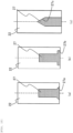
- Fig. 5 is a view schematically showing the flow of a magnetic flux 170 between the object to be conveyed 110 and the tooth 122 in (a) of Fig. 2 , that is, in the example of the related art.
- Fig. 6 is a view schematically showing the flow of a magnetic flux 70 between the object to be conveyed 110 and the tooth 22 in this embodiment (for example, the same configuration as in (b) of Fig. 2 ).
- An embodiment 3 is a configuration in which teeth without cavities are mixed in the embodiment 1 or 2.
- the embodiment 3 will be described, but descriptions of portions common to the embodiment 1 or 2 may be omitted.
- Fig. 7 is a schematic view showing a configuration example of a conveyance device according to the embodiment 3.
- the conveyance device includes a tooth 22c according to the embodiment 1 and another tooth 22d.
- the tooth 22c has a cavity 27 according to the embodiment 1, whereas another tooth 22d does not have the cavity 27.
- another tooth 22d can have the same configuration as that of the tooth of the related art.
- Fig. 8 is a schematic view showing another configuration example of the conveyance device according to the embodiment 3.
- the conveyance device includes a tooth 22e according to the embodiment 2 and another tooth 22d without the cavity 27.
- the tooth 22e has the cavity 27 according to the embodiment 2, whereas another tooth 22d does not have the cavity 27.
- the tooth 22c or 22e with the cavity 27 and another tooth 22d without the cavity 27 are mixed, thereby making it possible to take an advantage of each tooth.
- the arrangement of the tooth 22c or the tooth 22e and the tooth 22d can be freely designed.
- the tooth 22c or the tooth 22e having the cavity 27 can be disposed only at a location where highly accurate position detection is required when the object to be conveyed 110 is transferred to an analysis apparatus by a robot arm. In this manner, it is possible to selectively use the conveyance device in the conveyance path in consideration of one area where a thrust is emphasized and another area where a change in inductance is emphasized.
- the configuration of the conveyance device is not limited to the examples in Figs. 7 and 8 .
- three types of teeth 22c, 22d, and 22e may be mixed in one conveyance device.
- An embodiment 4 shows specific examples of the shapes of the tooth 22 and the cavity 27 that can be used in the embodiments 1 to 3.
- Fig. 9 is a schematic cross-sectional view showing various examples of the tooth 22 and the cavity 27 according to the embodiment 4.
- the outer periphery of the cross section in the axial direction of the tooth 22 has a circular shape in (a1) to (a5) of Fig. 9 , and has a square shape in (b1) to (b5) of Fig. 9 .
- the inner periphery of the cross section in the axial direction of the tooth 22 (that is, shape of the cavity 27) has a circular shape in (a1) of Fig. 9 , a square shape in (a2) of Fig. 9 , a regular hexagon shape in (a3) of Fig. 9 , a square shape in (a4) of Fig.
- the cavity 27 (at least a part of the cavity 27) has a shape to be rotationally symmetric with respect to the axis of the tooth 22. In this manner, the characteristics of thrust and inductance do not change depending on the conveyance direction of the object to be conveyed 110, thereby obtaining a desirable configuration.
- the characteristics of thrust and inductance do not change depending on the direction of conveyance when the object to be conveyed 110 is conveyed in the y-axis direction, thereby obtaining a desirable configuration.
- the characteristics of thrust and inductance do not change depending on the direction of conveyance when the object to be conveyed 110 is conveyed in the x-axis direction, thereby obtaining a desirable configuration.
- An embodiment 5 shows further specific examples of the shapes of the tooth 22 and the cavity 27 that can be used in the embodiments 1 to 3. Particularly, in the embodiments 1 and 2, the shape of the cavity 27 is constant in the axial direction, whereas, in the embodiment 5, the shape of the cavity 27 varies in the axial direction.
- Fig. 10 is a schematic cross-sectional view showing various examples of the tooth 22 and the cavity 27 according to the embodiment 5.
- An alternate long and short dash line indicates the axis of the tooth 22.
- the axis of the cavity 27 coincides with the axis of the tooth 22 in each example of Fig. 10 .
- the cavity 27 has a tapered portion 27a provided in the vicinity of an opening end and configured to widen toward the opening end.
- the cavity 27 has a stepped portion 27b having an enlarged diameter in the vicinity of the opening end.
- the cavity 27 has a conical portion 27c in the vicinity of the bottom portion.
- the cross-sectional shape of the cavity 27 by the cross section perpendicular to the axial direction changes in the axial direction.
- the tooth 22 can be easily manufactured and fixed to the yoke 26.
Landscapes
- Physics & Mathematics (AREA)
- Electromagnetism (AREA)
- Engineering & Computer Science (AREA)
- Power Engineering (AREA)
- Chemical & Material Sciences (AREA)
- Analytical Chemistry (AREA)
- General Health & Medical Sciences (AREA)
- General Physics & Mathematics (AREA)
- Immunology (AREA)
- Pathology (AREA)
- Biochemistry (AREA)
- Life Sciences & Earth Sciences (AREA)
- Health & Medical Sciences (AREA)
- Combustion & Propulsion (AREA)
- Non-Mechanical Conveyors (AREA)
- Linear Motors (AREA)
- Automatic Analysis And Handling Materials Therefor (AREA)
Abstract
Description
- The present invention relates to a conveyance device. The conveyance device is used for, for example, a specimen analysis system configured to analyze biological samples such as blood and urine, and a specimen pretreatment device configured to perform pretreatment necessary for analysis.
- In a specimen analysis system configured to analyze biological samples such as blood, plasma, serum, urine, and other body fluids (hereinafter sometimes referred to as "specimens"), in order to inspect a specified analysis item for each specimen, a device having a plurality of functions is connected and each step is automatically processed. In other words, in the specimen analysis system, analysis units in a plurality of analysis fields such as biochemistry and immunology are connected by a conveyance line, and a plurality of analyses are performed collectively.
- A conveyance method of the conveyance line includes (1) a method by a belt conveyor and (2) a method using an electromagnetic attraction force as thrust. In the example of the method (2), a permanent magnet is provided in a container carrier such as a holder that holds a specimen, and an electromagnetic attraction force generated by supplying a current to a winding of a magnetic circuit provided on a transfer surface is used as thrust for the container carrier. The magnetic circuit includes teeth disposed in a lattice shape, windings attached to the teeth, and a yoke connecting each of the teeth. These conveyance methods have a container carrier detection device provided therein and configured to detect the position of a magnetically active device provided in the container carrier.
- In
PTL 1, a container carrier detection device is provided to detect the presence and position of the container carrier located on a conveyance plane. It is described that a printed circuit board having a plurality of IR-based reflective light barriers is provided. - In PTL 2, a laboratory sample distribution system includes a transfer surface. A plurality of electromagnetic actuators are disposed below the transfer surface. Furthermore, a plurality of position sensors are distributed on the transfer surface. It is described that the position sensor is embodied as a Hall sensor.
- In order to reduce the loss due to winding, it is desirable that an electromagnetic attraction force per current is large. In order to improve the electromagnetic attraction force, it is effective to increase the tooth diameter so as to increase the area facing a magnet. Furthermore, in order to reduce costs, it is desirable to eliminate the detection device described in
PTL 1 and PTL 2 and implement a sensorless method. - One of the sensorless methods is to use a change in inductance in a winding of a magnetic circuit. In this method, the amount of a magnetic flux of a permanent magnet interlinking with the winding increases when a container carrier approaches teeth of the energized winding. Accordingly, the magnetic flux in the teeth is saturated and the inductance of the winding is changed. That is, the inductance has dependence on the position of the permanent magnet provided in the container carrier, which is used for detection. When position detection is performed without a sensor, detection accuracy is improved by increasing a change in inductance.
-
- PTL 1:
JP2017-77971A - PTL 2:
JP2017-102103A - However, in the related art, when a change in inductance is increased, thrust deteriorates, which causes a trade-off problem.
- In order to improve a change in inductance, it is effective, for example, to reduce the diameter of a tooth and form a structure that facilitates a magnetic saturation phenomenon. However, when the diameter of the tooth is reduced in order to improve the change in inductance, an electromagnetic attraction force is reduced as described above, which results in deterioration in thrust.
- The present invention has been made to solve the above-described problems, and an object of the present invention is to provide a conveyance device capable of increasing a change in inductance while suppressing deterioration in thrust.
- An example of a conveyance device according to the present invention is a conveyance device configured to convey an object to be conveyed, in which
- the object to be conveyed is conveyable by a magnetic force,
- the conveyance device includes:
- a plurality of electromagnets, each of the electromagnets including a tooth and a winding wound around the tooth, the tooth including a magnetic body;
- a yoke configured to magnetically couple the respective electromagnets; and
- a driving circuit configured to supply a current to the winding, and
- the tooth has a cavity formed to extend in an axial direction.
- This description includes the disclosed contents of
Japanese Patent Application No. 2020-175128 - With a conveyance device according to the present invention, it is possible to increase a change in inductance while suppressing deterioration in thrust. Other problems and effects will be clarified by descriptions of the following embodiments.
-
- [
Fig. 1] Fig. 1 is a schematic configuration view of a conveyance device according to anembodiment 1 of the present invention. - [
Fig. 2] Fig. 2 is a schematic cross-sectional comparison view showing a configuration of the conveyance device inFig. 1 . - [
Fig. 3] Fig. 3 is a graph comparing characteristics of thrust and inductance in a conveyance device of (a) ofFig. 2 and a conveyance device of (b) ofFig. 2 . - [
Fig. 4] Fig. 4 is a schematic cross-sectional view showing a configuration example of a conveyance device according to an embodiment 2. - [
Fig. 5] Fig. 5 is a view schematically showing the flow of a magnetic flux between an object to be conveyed and a tooth in (a) ofFig. 2 . - [
Fig. 6] Fig. 6 is a view schematically showing the flow of a magnetic flux between an object to be conveyed and a tooth in (b) ofFig. 2 . - [
Fig. 7] Fig. 7 is a schematic view showing a configuration example of a conveyance device according to an embodiment 3. - [
Fig. 8] Fig. 8 is a schematic view showing another configuration example of the conveyance device according to the embodiment 3. - [
Fig. 9] Fig. 9 is a schematic cross-sectional view showing various examples of a tooth and a cavity according to an embodiment 4. - [
Fig. 10] Fig. 10 is a schematic cross-sectional view showing various examples of a tooth and a cavity according to an embodiment 5. - Hereinafter, embodiments of the present invention will be described with reference to the drawings. In addition, the present invention is not limited to the following embodiments, and the shape, arrangement, and other configurations of the embodiments may be changed.
-
Fig. 1 is a schematic configuration view of a conveyance device according to anembodiment 1 of the present invention. Theconveyance device 1 of the present invention is a conveyance device configured to convey an object to be conveyed 110. Theconveyance device 1 forms a conveyance path along which the object to be conveyed 110 moves. The conveyance path is formed, for example, on the plane, and as a specific example, the same is formed on the horizontal plane. - The
conveyance device 1 includeselectromagnets electromagnets conveyance device 1 also includes drivingcircuits electromagnets electromagnets power source 55 is connected to the drivingcircuits power source 55 is, for example, a battery, and supplies direct current, but may also supply pulse current.Current detectors electromagnets circuits current detectors calculation unit 41. - Each configuration will be described in detail below. The object to be conveyed 110 can be conveyed by a magnetic force, and includes a magnet (for example, a permanent magnet). As a specific example, a permanent magnet (not shown) is built in the bottom surface of the object to be conveyed 110 (that is, the surface facing the conveyance path). An example of the object to be conveyed 110 is a specimen holder. The specimen holder holds specimen containers one by one. The specimen container may be a test tube containing a liquid specimen (or may be reagent) or may be a sample cell. Another example of the object to be conveyed 110 is a specimen rack. The specimen rack can hold a plurality of specimen containers. A neodymium alloy, ferrite, or the like is preferably used as the permanent magnet provided on the object to be conveyed 110. An electromagnet may be used instead of the permanent magnet, or a magnetic body (for example, a soft magnetic body) may be used.
- A conveyance path (not shown) is provided between the object to be conveyed 110 and the
electromagnets - The
electromagnets teeth teeth electromagnets windings teeth Figs. 10 ) can be defined for theteeth windings teeth teeth teeth Fig. 1 , the same is not limited to the cylindrical shape and may have a prismatic shape. - The
windings electromagnets circuits circuits windings electromagnets teeth teeth Fig. 6 and the like). This magnetic field generates a thrust in the permanent magnet of the object to be conveyed 110. - Each of the
current detectors windings electromagnets calculation unit 41. The specific structure of thecurrent detectors - The
calculation unit 41 calculates inductance of each of theelectromagnets calculation unit 41 calculates, based on the inductance, a relative positional relationship between each of theteeth calculation unit 41 calculates, based on this positional relationship, the position of the object to be conveyed 110 within theconveyance device 1. In this manner, theconveyance device 1 functions as a detection device configured to detect the position of the object to be conveyed 110 based on a change in inductance of thewindings - In addition, the
calculation unit 41 determines, based on the calculated position of the object to be conveyed 110, the amount of currents to be respectively supplied to the drivingcircuits circuits calculation unit 41 generates a control signal to move the object to be conveyed 110 based on the determined amount of currents and timing, and outputs the control signal to each of the drivingcircuits circuits electromagnets - Next, the structure of the
teeth Fig. 2 is a schematic cross-sectional comparison view showing the configuration of theconveyance device 1. (a) ofFig. 2 shows a configuration example of atooth 122 according to the related art, and (b) ofFig. 2 shows a configuration example of atooth 22 according to this embodiment. - Both the conveyance device in (a) of
Fig. 2 and theconveyance device 1 in (b) ofFig. 2 include ayoke 26. Theyoke 26 magnetically couples a plurality of electromagnets, thereby forming a magnetic circuit. The magnetic circuit is formed through the inner periphery of the winding 21, theyoke 26, and the outer periphery of the winding 21 (that is, formed between two adjacent windings 21). - In (a) of
Fig. 2 , that is, in the related art, thetooth 122 does not have a cavity. In (b) ofFig. 2 , that is, in this embodiment, thetooth 22 has acavity 27. Thecavity 27 is hatched in (b) ofFig. 2 . Thecavity 27 extends in the axial direction. In this embodiment, thecavity 27 is opened on the surface that does not face the object to be conveyed 110 (for example, toward negative direction of the z-axis). - In (a) of
Fig. 2 , that is, in the related art, the outer diameter of the end of thetooth 22 is the same as the inner diameter of ahole 28 so that thetooth 22 can be inserted into and fixed to thehole 28 of theyoke 26. InFig. 2(b) , that is, in this embodiment, thecavity 27 has a circular cross-sectional shape in the axial direction. Further, thecavity 27 includes the axis of the tooth 22 (more strictly, the same includes a certain line segment forming the axis of the tooth 22). Particularly, in this embodiment, the axis of thecavity 27 and the axis of thetooth 22 match each other. That is, the central axis of thecavity 27 and the central axis of thetooth 22 are commonly used. - In (b) of
Fig. 2 , theyoke 26 is provided with ahole 28 having the same inner diameter as that of thecavity 27 of the tooth. In (b) ofFig. 2 , thehole 28 is shown in a dot pattern. In this embodiment, theconveyance device 1 includes anon-magnetic body 29 inserted into thecavity 27. For convenience of illustration, (b) ofFig. 2 shows a state in which thenon-magnetic body 29 is inserted into only onecavity 27, but in fact, the samenon-magnetic body 29 is inserted into each of thecavities 27. For example, thenon-magnetic body 29 can be formed as a pin or a screw. Thetooth 22 can be fixed to theyoke 26 by allowing thenon-magnetic body 29 to be inserted into and fixed to thecavity 27 of thetooth 22 and thehole 28 of theyoke 26. - Here, in the configuration of (b) of
Fig. 2 , since thecavity 27 is opened on a surface of thetooth 22, the surface not facing the object to be conveyed 110, insertion work of thenon-magnetic body 29 can be performed without interfering with the conveyance path, which simplifies the manufacturing process of theconveyance device 1. - Further, in the configuration of (b) of
Fig. 2 , since the axis of thecavity 27 and the axis of thetooth 22 match each other, symmetry of thewhole teeth 22 is maintained, and the design of the magnetic circuit and control is easy. -
Fig. 3 is a graph comparing characteristics of thrust and inductance in (a) ofFig. 2 , that is, the conveyance device of the related art and (b) ofFig. 2 , that is, theconveyance device 1 of this embodiment. The X-axis represents the position of the object to be conveyed 110, X = 0 is the axial position of acertain tooth 22, and X = p is the axial position of anadjacent tooth 22. (a) ofFig. 3 shows thrust characteristics, and (b) ofFig. 3 shows inductance characteristics. Thecalculation unit 41 can calculate, based on the calculated inductance and the relationship shown in (b) ofFig. 3 , a relative positional relationship between each tooth and the object to be conveyed 110. - In both (a) and (b) of
Fig. 3 , an alternate long and short dash line corresponds to the configuration of (a) ofFig. 2 , and a solid line corresponds to (b) ofFig. 2 , that is, the configuration of this embodiment. When the object to be conveyed 110 moves from X = 0 to X = p, thrust and inductance with respect to the position change as shown inFigs. 3 . - Looking at the thrust characteristics in (a) of
Fig. 3 , the thrust is almost the same between (a) and (b) ofFig. 2 . On the other hand, looking at the inductance characteristics in (b) ofFig. 3 , as compared with (a) ofFig. 2 , that is, the case of the related art, in (b) ofFig. 2 , that is, the case of this embodiment, a difference between inductance at X = 0 and inductance at X = p is large. As described above, thecavity 27 as shown in (b) ofFig. 2 is provided, thereby making it possible to improve accuracy of position detection by increasing a change in inductance while suppressing deterioration in thrust. - It is conceivable that, for example, the area of a surface of the
tooth 22, the surface facing the object to be conveyed 110, is substantially maintained, and as such, deterioration in thrust is suppressed. Further, as a reason for a large change in inductance, for example, it is conceivable that the cross-sectional area of the magnetic circuit is reduced by thecavity 27. - As described above, since the
cavity 27 is provided, it is possible to improve accuracy of position detection by increasing a change in inductance while keeping the outer diameter of thetooth 22 large and suppressing deterioration in thrust. - An embodiment 2 has a configuration in which the cavity penetrates the tooth in the
embodiment 1. Hereinafter, the embodiment 2 will be described, but descriptions of portions common to theembodiment 1 may be omitted. -
Fig. 4 is a schematic cross-sectional view showing a configuration example of a conveyance device according to the embodiment 2. Acavity 27 penetrates atooth 22. In the same manner as that of theembodiment 1, the central axis of thecavity 27 coincides with the central axis oftooth 22. One end of thetooth 22 has a reduced outer diameter, and the one end is inserted into ahole 28 of ayoke 26, thereby making it possible to allow thetooth 22 and theyoke 26 to be joined and fixed. Therefore, it is not necessary to use a member (such as a non-magnetic pin or screw) configured to fix thetooth 22 to theyoke 26. - Since the
cavity 27 penetrates thetooth 22, thecavity 27 can be used as a coolant flow path. For example, an air blower is installed to blow air into thecavity 27, thereby making it possible to suppress temperature rise of theconveyance device 1 due to heat generation of a winding 21. -
Fig. 5 is a view schematically showing the flow of amagnetic flux 170 between the object to be conveyed 110 and thetooth 122 in (a) ofFig. 2 , that is, in the example of the related art.Fig. 6 is a view schematically showing the flow of amagnetic flux 70 between the object to be conveyed 110 and thetooth 22 in this embodiment (for example, the same configuration as in (b) ofFig. 2 ). - As shown in
Fig. 6 , since the cavity 27 (shown by hatching) penetrates thetooth 22, the area of a facingsurface 23 of thetooth 22, the facingsurface 23 facing the object to be conveyed 110, is reduced. However, in both cases ofFigs. 5 and6 , most of themagnetic fluxes portions 24 and 124 (or a part of theportions 24 and 124) in the vicinity of the outer peripheries of the facing surfaces 23 and 123. This is because themagnetic fluxes Fig. 6 , even if thecavity 27 is configured to penetrate the tooth, thecavity 27 is located in the vicinity of the axis of the facingsurface 23 of thetooth 22, thereby making it possible to suppress deterioration in thrust. - An embodiment 3 is a configuration in which teeth without cavities are mixed in the
embodiment 1 or 2. Hereinafter, the embodiment 3 will be described, but descriptions of portions common to theembodiment 1 or 2 may be omitted. -
Fig. 7 is a schematic view showing a configuration example of a conveyance device according to the embodiment 3. The conveyance device includes atooth 22c according to theembodiment 1 and anothertooth 22d. Thetooth 22c has acavity 27 according to theembodiment 1, whereas anothertooth 22d does not have thecavity 27. For example, anothertooth 22d can have the same configuration as that of the tooth of the related art. -
Fig. 8 is a schematic view showing another configuration example of the conveyance device according to the embodiment 3. The conveyance device includes atooth 22e according to the embodiment 2 and anothertooth 22d without thecavity 27. Thetooth 22e has thecavity 27 according to the embodiment 2, whereas anothertooth 22d does not have thecavity 27. - As described above, the
tooth cavity 27 and anothertooth 22d without thecavity 27 are mixed, thereby making it possible to take an advantage of each tooth. - The arrangement of the
tooth 22c or thetooth 22e and thetooth 22d can be freely designed. For example, thetooth 22c or thetooth 22e having thecavity 27 can be disposed only at a location where highly accurate position detection is required when the object to be conveyed 110 is transferred to an analysis apparatus by a robot arm. In this manner, it is possible to selectively use the conveyance device in the conveyance path in consideration of one area where a thrust is emphasized and another area where a change in inductance is emphasized. - The configuration of the conveyance device is not limited to the examples in
Figs. 7 and8 . For example, three types ofteeth - An embodiment 4 shows specific examples of the shapes of the
tooth 22 and thecavity 27 that can be used in theembodiments 1 to 3. -
Fig. 9 is a schematic cross-sectional view showing various examples of thetooth 22 and thecavity 27 according to the embodiment 4. The outer periphery of the cross section in the axial direction of thetooth 22 has a circular shape in (a1) to (a5) ofFig. 9 , and has a square shape in (b1) to (b5) ofFig. 9 . In addition, the inner periphery of the cross section in the axial direction of the tooth 22 (that is, shape of the cavity 27) has a circular shape in (a1) ofFig. 9 , a square shape in (a2) ofFig. 9 , a regular hexagon shape in (a3) ofFig. 9 , a square shape in (a4) ofFig. 9 (note that, direction of thecavity 27 with respect to arrangement direction of thetooth 22 is different from that in (a2) ofFig. 9 ), a regular octagon shape in (a5) ofFig. 9 , a square shape in (b1) ofFig. 9 , a square shape in (b2) ofFig. 9 (note that, direction of thecavity 27 with respect to the arrangement direction of thetooth 22 is different from that in (b1) ofFig. 9 ), a regular octagon shape in (b3) ofFig. 9 , a circular shape in (b4) ofFig. 9 , and a regular hexagon shape in (b5) ofFig. 9 . - In any configuration shown in
Fig. 9 , the cavity 27 (at least a part of the cavity 27) has a shape to be rotationally symmetric with respect to the axis of thetooth 22. In this manner, the characteristics of thrust and inductance do not change depending on the conveyance direction of the object to be conveyed 110, thereby obtaining a desirable configuration. - Further, when the shape of the
cavity 27 is plane-symmetric with respect to the xz plane, the characteristics of thrust and inductance do not change depending on the direction of conveyance when the object to be conveyed 110 is conveyed in the y-axis direction, thereby obtaining a desirable configuration. In the same manner, when the shape of thecavity 27 is plane-symmetric with respect to the yz plane, the characteristics of thrust and inductance do not change depending on the direction of conveyance when the object to be conveyed 110 is conveyed in the x-axis direction, thereby obtaining a desirable configuration. - An embodiment 5 shows further specific examples of the shapes of the
tooth 22 and thecavity 27 that can be used in theembodiments 1 to 3. Particularly, in theembodiments 1 and 2, the shape of thecavity 27 is constant in the axial direction, whereas, in the embodiment 5, the shape of thecavity 27 varies in the axial direction. -
Fig. 10 is a schematic cross-sectional view showing various examples of thetooth 22 and thecavity 27 according to the embodiment 5. An alternate long and short dash line indicates the axis of thetooth 22. The axis of thecavity 27 coincides with the axis of thetooth 22 in each example ofFig. 10 . - In the example of (a) of
Fig. 10 , thecavity 27 has a taperedportion 27a provided in the vicinity of an opening end and configured to widen toward the opening end. In the example of (b) ofFig. 10 , thecavity 27 has a steppedportion 27b having an enlarged diameter in the vicinity of the opening end. In the example of (c) ofFig. 10 , thecavity 27 has aconical portion 27c in the vicinity of the bottom portion. - In any configuration shown in
Fig. 10 , the cross-sectional shape of thecavity 27 by the cross section perpendicular to the axial direction changes in the axial direction. By changing the cross-sectional shape in this manner, thetooth 22 can be easily manufactured and fixed to theyoke 26. -
- 1: conveyance device
- 21, 21a, 21b: winding
- 22, 22a, 22b, 22c, 22e: tooth
- 22d: another tooth
- 23: facing surface
- 24: portion in the vicinity of outer periphery of facing surface
- 25a, 25b: electromagnet
- 26: yoke
- 27: cavity
- 28: hole
- 29: non-magnetic body
- 40a, 40b: current detector
- 41: calculation unit
- 50a, 50b: driving circuit
- 55: power source
- 70: magnetic flux
- 110: object to be conveyed
- All publications, patents, and patent applications cited in the description are incorporated herein by reference in their entirety.
Claims (9)
- A conveyance device configured to convey an object to be conveyed, whereinthe object to be conveyed is conveyable by a magnetic force,the conveyance device comprises:a plurality of electromagnets, each of the electromagnets including a tooth and a winding wound around the tooth, the tooth including a magnetic body;a yoke configured to magnetically couple the respective electromagnets; anda driving circuit configured to supply a current to the winding, andthe tooth has a cavity formed to extend in an axial direction.
- The conveyance device according to claim 1, wherein the cavity is opened on a surface of the tooth, the surface not facing the object to be conveyed.
- The conveyance device according to claim 1, wherein the cavity penetrates the tooth.
- The conveyance device according to claim 1, further comprising a non-magnetic body inserted into the cavity.
- The conveyance device according to claim 1, further comprising another tooth,
wherein the another tooth does not have the cavity formed to extend in the axial direction. - The conveyance device according to claim 1, wherein a cross-sectional shape of the cavity by a cross section perpendicular to the axial direction changes in the axial direction.
- The conveyance device according to claim 1, further comprising a detection device configured to detect, based on a change in inductance of the winding, a position of the object to be conveyed.
- The conveyance device according to claim 1, wherein an axis of the cavity and an axis of the tooth match each other.
- The conveyance device according to claim 1, wherein the cavity has a shape rotationally symmetric with respect to an axis of the tooth.
Applications Claiming Priority (2)
| Application Number | Priority Date | Filing Date | Title |
|---|---|---|---|
| JP2020175128A JP7410007B2 (en) | 2020-10-19 | 2020-10-19 | Conveyance device |
| PCT/JP2021/031206 WO2022085299A1 (en) | 2020-10-19 | 2021-08-25 | Conveyance device |
Publications (2)
| Publication Number | Publication Date |
|---|---|
| EP4230556A1 true EP4230556A1 (en) | 2023-08-23 |
| EP4230556A4 EP4230556A4 (en) | 2024-04-03 |
Family
ID=81291238
Family Applications (1)
| Application Number | Title | Priority Date | Filing Date |
|---|---|---|---|
| EP21882440.7A Pending EP4230556A4 (en) | 2020-10-19 | 2021-08-25 | CONVEYING DEVICE |
Country Status (5)
| Country | Link |
|---|---|
| US (1) | US12304752B2 (en) |
| EP (1) | EP4230556A4 (en) |
| JP (1) | JP7410007B2 (en) |
| CN (1) | CN116490781B (en) |
| WO (1) | WO2022085299A1 (en) |
Families Citing this family (1)
| Publication number | Priority date | Publication date | Assignee | Title |
|---|---|---|---|---|
| WO2026163537A1 (en) * | 2025-01-31 | 2026-08-06 | 株式会社日立ハイテク | Electromagnetic conveyance tile, conveyance device, and conveyance system |
Family Cites Families (11)
| Publication number | Priority date | Publication date | Assignee | Title |
|---|---|---|---|---|
| GB662691A (en) * | 1948-08-05 | 1951-12-12 | Aladdin Ind Inc | Improvements in or relating to variable inductances |
| JPH0616239A (en) * | 1992-06-29 | 1994-01-25 | Hitachi Ltd | Magnetic levitation carrier |
| GB9613061D0 (en) * | 1995-09-02 | 1996-08-28 | Magnetic Patent Holdings Ltd | Magnetic suspension system |
| CN103094171B (en) * | 2011-10-27 | 2015-06-17 | 沈阳芯源微电子设备有限公司 | Magnetic levitation wafer rotary system |
| EP2589967A1 (en) | 2011-11-04 | 2013-05-08 | Roche Diagnostics GmbH | Laboratory sample distribution system and corresponding method of operation |
| DE102011089417B4 (en) * | 2011-12-21 | 2017-05-04 | Siemens Aktiengesellschaft | Active part for an electrical machine with a connecting fiber |
| JP6304560B2 (en) * | 2015-03-12 | 2018-04-04 | 株式会社安川電機 | Linear motor, linear motor control system |
| EP3156352B1 (en) * | 2015-10-13 | 2019-02-27 | Roche Diagniostics GmbH | Laboratory sample distribution system and laboratory automation system |
| JP7325184B2 (en) | 2018-12-27 | 2023-08-14 | 株式会社日立ハイテク | Transport device, sample analysis system equipped with the same, sample pretreatment device |
| JP2020175128A (en) | 2019-04-22 | 2020-10-29 | 株式会社ショウエイ | Bathing water circulation filtration system |
| JP7319096B2 (en) * | 2019-06-12 | 2023-08-01 | 株式会社日立ハイテク | Conveyor |
-
2020
- 2020-10-19 JP JP2020175128A patent/JP7410007B2/en active Active
-
2021
- 2021-08-25 US US18/029,398 patent/US12304752B2/en active Active
- 2021-08-25 WO PCT/JP2021/031206 patent/WO2022085299A1/en not_active Ceased
- 2021-08-25 CN CN202180063142.0A patent/CN116490781B/en active Active
- 2021-08-25 EP EP21882440.7A patent/EP4230556A4/en active Pending
Also Published As
| Publication number | Publication date |
|---|---|
| WO2022085299A1 (en) | 2022-04-28 |
| EP4230556A4 (en) | 2024-04-03 |
| US20230365354A1 (en) | 2023-11-16 |
| CN116490781A (en) | 2023-07-25 |
| CN116490781B (en) | 2026-06-30 |
| JP2022066656A (en) | 2022-05-02 |
| JP7410007B2 (en) | 2024-01-09 |
| US12304752B2 (en) | 2025-05-20 |
Similar Documents
| Publication | Publication Date | Title |
|---|---|---|
| EP3905515B1 (en) | Conveying device, sample analysis system and sample preprocessing device comprising same, and method for conveying sample to be conveyed | |
| EP3355065B1 (en) | Laboratory sample distribution system and laboratory automation system | |
| CN112840214B (en) | Transport device, specimen analysis system and specimen pre-processing device equipped with the same | |
| US11772911B2 (en) | Conveying device | |
| US12304752B2 (en) | Conveyance device | |
| US12098039B2 (en) | Body-to-be-conveyed, container carrier, and conveying device | |
| US12230441B2 (en) | Transport device and transport method | |
| US12480964B2 (en) | Specimen transport system and specimen transport method | |
| US20250074721A1 (en) | Transport Device, Specimen Analysis System Comprising Transport Device, and Specimen Pre-Treatment Device Comprising Transport Device | |
| US20250145393A1 (en) | Conveying device and conveying method | |
| US20250224415A1 (en) | Conveying Device, Specimen Analysis System Provided With Conveying Device, and Specimen Pretreatment Device Provided With Conveying Device | |
| EP4269296B1 (en) | Specimen transportation device | |
| CN117242352A (en) | Specimen transport device, specimen analysis system and specimen transport method | |
| CN116324421B (en) | Conveying device | |
| JP7825512B2 (en) | Conveyor | |
| US20240192241A1 (en) | Sample Conveying Device, Sample Analysis System, and Sample Pretreatment System | |
| EP4641213A1 (en) | Sample carrier, conveyance device, and method for conveying sample carrier | |
| WO2026048157A1 (en) | Electromagnetic specimen transport device, specimen analysis system, and specimen pretreatment device | |
| WO2025253761A1 (en) | Conveyance device, specimen analysis system including same, and abnormality detection method in conveyance device | |
| JP2025161371A (en) | Specimen transport device, specimen analysis system, and specimen pretreatment device | |
| JP2025097685A (en) | Specimen conveying device, specimen analysis system, and specimen pretreatment device |
Legal Events
| Date | Code | Title | Description |
|---|---|---|---|
| STAA | Information on the status of an ep patent application or granted ep patent |
Free format text: STATUS: THE INTERNATIONAL PUBLICATION HAS BEEN MADE |
|
| PUAI | Public reference made under article 153(3) epc to a published international application that has entered the european phase |
Free format text: ORIGINAL CODE: 0009012 |
|
| STAA | Information on the status of an ep patent application or granted ep patent |
Free format text: STATUS: REQUEST FOR EXAMINATION WAS MADE |
|
| 17P | Request for examination filed |
Effective date: 20230329 |
|
| AK | Designated contracting states |
Kind code of ref document: A1 Designated state(s): AL AT BE BG CH CY CZ DE DK EE ES FI FR GB GR HR HU IE IS IT LI LT LU LV MC MK MT NL NO PL PT RO RS SE SI SK SM TR |
|
| DAV | Request for validation of the european patent (deleted) | ||
| DAX | Request for extension of the european patent (deleted) | ||
| A4 | Supplementary search report drawn up and despatched |
Effective date: 20240301 |
|
| RIC1 | Information provided on ipc code assigned before grant |
Ipc: H02K 1/08 20060101ALI20240226BHEP Ipc: H02K 41/03 20060101ALI20240226BHEP Ipc: G01N 35/04 20060101ALI20240226BHEP Ipc: B65G 54/02 20060101AFI20240226BHEP |