EP4230546A1 - Metal profile and pallet comprising said metal profile - Google Patents
Metal profile and pallet comprising said metal profile Download PDFInfo
- Publication number
- EP4230546A1 EP4230546A1 EP23156716.5A EP23156716A EP4230546A1 EP 4230546 A1 EP4230546 A1 EP 4230546A1 EP 23156716 A EP23156716 A EP 23156716A EP 4230546 A1 EP4230546 A1 EP 4230546A1
- Authority
- EP
- European Patent Office
- Prior art keywords
- profile
- sections
- cross
- pallet
- comprised
- Prior art date
- Legal status (The legal status is an assumption and is not a legal conclusion. Google has not performed a legal analysis and makes no representation as to the accuracy of the status listed.)
- Granted
Links
Images









Classifications
-
- B—PERFORMING OPERATIONS; TRANSPORTING
- B65—CONVEYING; PACKING; STORING; HANDLING THIN OR FILAMENTARY MATERIAL
- B65D—CONTAINERS FOR STORAGE OR TRANSPORT OF ARTICLES OR MATERIALS, e.g. BAGS, BARRELS, BOTTLES, BOXES, CANS, CARTONS, CRATES, DRUMS, JARS, TANKS, HOPPERS, FORWARDING CONTAINERS; ACCESSORIES, CLOSURES, OR FITTINGS THEREFOR; PACKAGING ELEMENTS; PACKAGES
- B65D19/00—Pallets or like platforms, with or without side walls, for supporting loads to be lifted or lowered
- B65D19/0004—Rigid pallets without side walls
- B65D19/0053—Rigid pallets without side walls the load supporting surface being made of more than one element
- B65D19/0077—Rigid pallets without side walls the load supporting surface being made of more than one element forming discontinuous or non-planar contact surfaces
- B65D19/0089—Rigid pallets without side walls the load supporting surface being made of more than one element forming discontinuous or non-planar contact surfaces the base surface being made of more than one element
- B65D19/0093—Rigid pallets without side walls the load supporting surface being made of more than one element forming discontinuous or non-planar contact surfaces the base surface being made of more than one element forming discontinuous or non-planar contact surfaces
- B65D19/0095—Rigid pallets without side walls the load supporting surface being made of more than one element forming discontinuous or non-planar contact surfaces the base surface being made of more than one element forming discontinuous or non-planar contact surfaces and each contact surface having a stringer-like shape
-
- B—PERFORMING OPERATIONS; TRANSPORTING
- B65—CONVEYING; PACKING; STORING; HANDLING THIN OR FILAMENTARY MATERIAL
- B65D—CONTAINERS FOR STORAGE OR TRANSPORT OF ARTICLES OR MATERIALS, e.g. BAGS, BARRELS, BOTTLES, BOXES, CANS, CARTONS, CRATES, DRUMS, JARS, TANKS, HOPPERS, FORWARDING CONTAINERS; ACCESSORIES, CLOSURES, OR FITTINGS THEREFOR; PACKAGING ELEMENTS; PACKAGES
- B65D2519/00—Pallets or like platforms, with or without side walls, for supporting loads to be lifted or lowered
- B65D2519/00004—Details relating to pallets
- B65D2519/00009—Materials
- B65D2519/00014—Materials for the load supporting surface
- B65D2519/00024—Metal
-
- B—PERFORMING OPERATIONS; TRANSPORTING
- B65—CONVEYING; PACKING; STORING; HANDLING THIN OR FILAMENTARY MATERIAL
- B65D—CONTAINERS FOR STORAGE OR TRANSPORT OF ARTICLES OR MATERIALS, e.g. BAGS, BARRELS, BOTTLES, BOXES, CANS, CARTONS, CRATES, DRUMS, JARS, TANKS, HOPPERS, FORWARDING CONTAINERS; ACCESSORIES, CLOSURES, OR FITTINGS THEREFOR; PACKAGING ELEMENTS; PACKAGES
- B65D2519/00—Pallets or like platforms, with or without side walls, for supporting loads to be lifted or lowered
- B65D2519/00004—Details relating to pallets
- B65D2519/00009—Materials
- B65D2519/00049—Materials for the base surface
- B65D2519/00059—Metal
-
- B—PERFORMING OPERATIONS; TRANSPORTING
- B65—CONVEYING; PACKING; STORING; HANDLING THIN OR FILAMENTARY MATERIAL
- B65D—CONTAINERS FOR STORAGE OR TRANSPORT OF ARTICLES OR MATERIALS, e.g. BAGS, BARRELS, BOTTLES, BOXES, CANS, CARTONS, CRATES, DRUMS, JARS, TANKS, HOPPERS, FORWARDING CONTAINERS; ACCESSORIES, CLOSURES, OR FITTINGS THEREFOR; PACKAGING ELEMENTS; PACKAGES
- B65D2519/00—Pallets or like platforms, with or without side walls, for supporting loads to be lifted or lowered
- B65D2519/00004—Details relating to pallets
- B65D2519/00009—Materials
- B65D2519/00084—Materials for the non-integral separating spacer
- B65D2519/00094—Metal
-
- B—PERFORMING OPERATIONS; TRANSPORTING
- B65—CONVEYING; PACKING; STORING; HANDLING THIN OR FILAMENTARY MATERIAL
- B65D—CONTAINERS FOR STORAGE OR TRANSPORT OF ARTICLES OR MATERIALS, e.g. BAGS, BARRELS, BOTTLES, BOXES, CANS, CARTONS, CRATES, DRUMS, JARS, TANKS, HOPPERS, FORWARDING CONTAINERS; ACCESSORIES, CLOSURES, OR FITTINGS THEREFOR; PACKAGING ELEMENTS; PACKAGES
- B65D2519/00—Pallets or like platforms, with or without side walls, for supporting loads to be lifted or lowered
- B65D2519/00004—Details relating to pallets
- B65D2519/00258—Overall construction
- B65D2519/00263—Overall construction of the pallet
- B65D2519/00273—Overall construction of the pallet made of more than one piece
-
- B—PERFORMING OPERATIONS; TRANSPORTING
- B65—CONVEYING; PACKING; STORING; HANDLING THIN OR FILAMENTARY MATERIAL
- B65D—CONTAINERS FOR STORAGE OR TRANSPORT OF ARTICLES OR MATERIALS, e.g. BAGS, BARRELS, BOTTLES, BOXES, CANS, CARTONS, CRATES, DRUMS, JARS, TANKS, HOPPERS, FORWARDING CONTAINERS; ACCESSORIES, CLOSURES, OR FITTINGS THEREFOR; PACKAGING ELEMENTS; PACKAGES
- B65D2519/00—Pallets or like platforms, with or without side walls, for supporting loads to be lifted or lowered
- B65D2519/00004—Details relating to pallets
- B65D2519/00258—Overall construction
- B65D2519/00283—Overall construction of the load supporting surface
- B65D2519/00293—Overall construction of the load supporting surface made of more than one piece
-
- B—PERFORMING OPERATIONS; TRANSPORTING
- B65—CONVEYING; PACKING; STORING; HANDLING THIN OR FILAMENTARY MATERIAL
- B65D—CONTAINERS FOR STORAGE OR TRANSPORT OF ARTICLES OR MATERIALS, e.g. BAGS, BARRELS, BOTTLES, BOXES, CANS, CARTONS, CRATES, DRUMS, JARS, TANKS, HOPPERS, FORWARDING CONTAINERS; ACCESSORIES, CLOSURES, OR FITTINGS THEREFOR; PACKAGING ELEMENTS; PACKAGES
- B65D2519/00—Pallets or like platforms, with or without side walls, for supporting loads to be lifted or lowered
- B65D2519/00004—Details relating to pallets
- B65D2519/00258—Overall construction
- B65D2519/00313—Overall construction of the base surface
- B65D2519/00323—Overall construction of the base surface made of more than one piece
-
- B—PERFORMING OPERATIONS; TRANSPORTING
- B65—CONVEYING; PACKING; STORING; HANDLING THIN OR FILAMENTARY MATERIAL
- B65D—CONTAINERS FOR STORAGE OR TRANSPORT OF ARTICLES OR MATERIALS, e.g. BAGS, BARRELS, BOTTLES, BOXES, CANS, CARTONS, CRATES, DRUMS, JARS, TANKS, HOPPERS, FORWARDING CONTAINERS; ACCESSORIES, CLOSURES, OR FITTINGS THEREFOR; PACKAGING ELEMENTS; PACKAGES
- B65D2519/00—Pallets or like platforms, with or without side walls, for supporting loads to be lifted or lowered
- B65D2519/00004—Details relating to pallets
- B65D2519/00258—Overall construction
- B65D2519/00313—Overall construction of the base surface
- B65D2519/00328—Overall construction of the base surface shape of the contact surface of the base
- B65D2519/00333—Overall construction of the base surface shape of the contact surface of the base contact surface having a stringer-like shape
-
- B—PERFORMING OPERATIONS; TRANSPORTING
- B65—CONVEYING; PACKING; STORING; HANDLING THIN OR FILAMENTARY MATERIAL
- B65D—CONTAINERS FOR STORAGE OR TRANSPORT OF ARTICLES OR MATERIALS, e.g. BAGS, BARRELS, BOTTLES, BOXES, CANS, CARTONS, CRATES, DRUMS, JARS, TANKS, HOPPERS, FORWARDING CONTAINERS; ACCESSORIES, CLOSURES, OR FITTINGS THEREFOR; PACKAGING ELEMENTS; PACKAGES
- B65D2519/00—Pallets or like platforms, with or without side walls, for supporting loads to be lifted or lowered
- B65D2519/00004—Details relating to pallets
- B65D2519/00258—Overall construction
- B65D2519/00368—Overall construction of the non-integral separating spacer
- B65D2519/00373—Overall construction of the non-integral separating spacer whereby at least one spacer is made of one piece
-
- B—PERFORMING OPERATIONS; TRANSPORTING
- B65—CONVEYING; PACKING; STORING; HANDLING THIN OR FILAMENTARY MATERIAL
- B65D—CONTAINERS FOR STORAGE OR TRANSPORT OF ARTICLES OR MATERIALS, e.g. BAGS, BARRELS, BOTTLES, BOXES, CANS, CARTONS, CRATES, DRUMS, JARS, TANKS, HOPPERS, FORWARDING CONTAINERS; ACCESSORIES, CLOSURES, OR FITTINGS THEREFOR; PACKAGING ELEMENTS; PACKAGES
- B65D2519/00—Pallets or like platforms, with or without side walls, for supporting loads to be lifted or lowered
- B65D2519/00004—Details relating to pallets
- B65D2519/00547—Connections
- B65D2519/00552—Structures connecting the constitutive elements of the pallet to each other, i.e. load supporting surface, base surface and/or separate spacer
- B65D2519/00557—Structures connecting the constitutive elements of the pallet to each other, i.e. load supporting surface, base surface and/or separate spacer without separate auxiliary elements
- B65D2519/00562—Structures connecting the constitutive elements of the pallet to each other, i.e. load supporting surface, base surface and/or separate spacer without separate auxiliary elements chemical connection, e.g. glued, welded, sealed
-
- B—PERFORMING OPERATIONS; TRANSPORTING
- B65—CONVEYING; PACKING; STORING; HANDLING THIN OR FILAMENTARY MATERIAL
- B65D—CONTAINERS FOR STORAGE OR TRANSPORT OF ARTICLES OR MATERIALS, e.g. BAGS, BARRELS, BOTTLES, BOXES, CANS, CARTONS, CRATES, DRUMS, JARS, TANKS, HOPPERS, FORWARDING CONTAINERS; ACCESSORIES, CLOSURES, OR FITTINGS THEREFOR; PACKAGING ELEMENTS; PACKAGES
- B65D2519/00—Pallets or like platforms, with or without side walls, for supporting loads to be lifted or lowered
- B65D2519/00004—Details relating to pallets
- B65D2519/00547—Connections
- B65D2519/00552—Structures connecting the constitutive elements of the pallet to each other, i.e. load supporting surface, base surface and/or separate spacer
- B65D2519/00572—Structures connecting the constitutive elements of the pallet to each other, i.e. load supporting surface, base surface and/or separate spacer with separate auxiliary element, e.g. screws, nails, bayonets
Definitions
- the present invention relates to a metal profile obtainable by bending a metal sheet.
- the profile is particularly suitable to produce pallets for packaging, transporting, and moving goods as well as to make for example traffic signs, enclosures, guard rails, frames of walls made of plasterboard, laminated wood or other composite walls or other metal carpentry structures.
- the main requirements a metal pallet must - or should - satisfy are low costs, ease of production, repair, recycle and disposal, strength.
- An object of the present invention is to solve the above-mentioned drawbacks of the state of the art and in particular to provide a metal profile suitable to produce metal pallets, and a metal pallet obtained therefrom, which proves to be meliorative with respect to known metal pallets.
- such object is achieved by a pallet having the features according to claim 12 .
- At least part and preferably all the profile sections ( 1, 1A, 1B, 1C ) are overall straight.
- Figures 1-3 , 3A, 3B show a metal profile according to a first particular embodiment of the present invention, denoted by the overall reference 1, 1A, 1B, 1C particularly suitable to make pallets - i.e., benches - for moving and transporting goods, pallets movable through forklift trucks.
- the profile 1, 1', 1" can be further used to make for example enclosures, lofts, raised floors, reticular frames - such as for example the shelves of the pallet holders (so-called racks) or the perimetral frames of the pallets (so-called collars) - frames of walls made of plasterboard, laminated wood or other composite walls or other structures for example of metal carpentry, guard rails, or traffic sign.
- reticular frames - such as for example the shelves of the pallet holders (so-called racks) or the perimetral frames of the pallets (so-called collars) - frames of walls made of plasterboard, laminated wood or other composite walls or other structures for example of metal carpentry, guard rails, or traffic sign.
- the profile 1, 1', 1" is preferably obtained by bending or otherwise cold deforming a metal sheet band, for example made of steel or aluminium alloys.
- Such sheet can have thicknesses for example comprised between 0.2-2 millimetres, or between 0.3-1.5 millimetres, between 0.3-1.2 millimetres or between 0.45-0.6 millimetres.
- the profile 1, 1', 1" is obtained by cold deforming a single metal sheet band.
- Such band can be deformed in a suitable roller machine, i.e., a profiling machine, provided with a plurality of rollers which progressively bend or otherwise deform the band advancing along the profiling machine itself.
- a suitable roller machine i.e., a profiling machine, provided with a plurality of rollers which progressively bend or otherwise deform the band advancing along the profiling machine itself.
- roller axes can be for example substantially perpendicular to the advancing direction of the band in the profiling machine, which direction is parallel to the axis AXP of the profile 1.
- the sheet band forms the so-called main body of the profile 1, 1', 1".
- the main body of the profile 1, 1', 1" is bent so as to form a first major face conventionally referred to as “dorsal” 3 and a second major face 5 of the profile conventionally referred to as “ventral”, wherein said major dorsal 3 and ventral 5 faces face two directions in space opposite to each other ( Figure 3 ).
- the profile 1, 1', 1" forms cross-sections substantially oblong in overall shape, wherein such cross-sections are related to ideal section planes perpendicular to the axis AXP of the profile 1, 1', 1".
- Such cross-sections form two lateral edges 7, 9, each of which is placed at a respective end of these cross-sections ( Figure 2 , 3 ).
- the profile 1, 1', 1" forms two respective tubular portions 11, 13, each of which is substantially tubular, hollow, in shape.
- Each tubular portion 11, 13 is preferably obtained by bending and folding on itself a strip of the sheet band so as to form closed cross-sections ( Figure 2 , 3 ), making the profile 1, 1', 1" particularly strength and resistant to deflection; for this purpose, such as for example in Figure 3 , 3A , the longitudinal edges of the sheet band can be folded on more internal portions of the same band so as to form tubular, or otherwise closed, cross-sections; however in not-shown embodiments the tubular portions can be also made with one or more sheet strips not entirely folded on themselves, and for example wound in a spiral or in a relatively very close C-shape.
- the tubular portions 11, 13 make the outer edges of the profile 1, 1', 1" rounded, preventing them from exposing dangerous sharp sheet edges which might injure, even seriously, the staff handling the profile 1, 1', 1" or a pallet 30, 30" obtained therefrom, or from damaging surrounding objects.
- Each tubular portion 11, 13 has a maximum width WTB substantially less than or equal to 0.3 times the overall length WP of the cross-sections of the profile 1 itself; in other words, in the profile 1 the ratio WTB/WP is preferably less than or equal to 0.3.
- the ratio WTB/WP is comprised between 0.15-0.27 times, and more preferably comprised between 0.18-0.25 times, between 0.19-0.23 times or between 0.19-0.21 times or approximately equal to 0.20 times.
- the central groove 15 forms a central longitudinal rib 16 on the major dorsal face 3 of the profile 1, 1', 1" ( Figure 3 ).
- the major dorsal face 3 forms at least one - and more preferably at least two - connecting recesses 18, each of which is located at one side of both a respective tubular portion 11, 13 and the central longitudinal rib 16.
- each connecting recess 18 is placed between a respective tubular portion 11, 13 and the central longitudinal rib 16 ( Figure 3 ).
- each connecting recess 18 can be delimited by a side of a respective tubular portion 11, 13, by a side of the central rib 16 and by the connecting portion 21.
- each connecting recess 18 of a first profile 1, 1', 1" is arranged to accommodate at least part of the tubular portion 11, 13 of a second profile 1, 1', 1" which is overlapped to the first profile 1, 1', 1" facing the major dorsal faces 3 of the two profiles.
- each tubular portion 11, 13 has a maximum height HTB substantially comprised between 0.5-1 times the maximum height HP of the cross-sections of the profile 1 itself; in other words in the profile 1 the ratio HTB/HP is preferably comprised between 0.5-1 times.
- the ratio HTB/HP is comprised between 0.7-0.9 times, or between 0.80-0.85 times or between 0.83-0.84 times.
- the cross-sections of the tubular portions 11, 13 are substantially oblong in shape, which extends preferably longitudinal to the direction along which the relative overall cross-section of the profile 1 ( Figure 3 ) extends.
- the ratio WTB/HTB between the maximum height and length of each tubular portion 11, 13 is preferably comprised between 0.3-2 times, and more preferably comprised between 0.5-1.8 times, between 1.2-1.7 times, between 1.6-1.7 times or between 1.65-1.69 times.
- the ratio RDST/WT between the square root RDST of the cross-sectional area of each tubular portion 11, 13 and the overall width WP of the profile 1 is comprised between 0.1-0.2 times, and more preferably comprised between 0.14-0.15 times or between 0.141-0.143 times and preferably equal to about 0.141 times.
- the ratio RDST/HP between the square root RDST of the cross-sectional area of each tubular portion 11, 13 and the maximum height HP of the profile 1 is preferably comprised between 0.8-1.3 times, and more preferably comprised between 0.9-0.97 times or between 0.95-0.96 times and preferably equal to about 0.958 times.
- the ratio RDST/PRT between the square root RDST of the cross-sectional area of each tubular portion 11, 13 and the perimeter PRT of such tubular section 11, 13 is preferably comprised between 0.2-0.28 times, and more preferably comprised between 0.22-0.24 times or between 0.23-0.24 times and preferably equal to about 0.235 times.
- each tubular portion 11, 13 is obtained by folding on itself an edge or other strip of the sheet which forms the profile 1, for example by folding the sheet edge on one of the connecting portions 21 of the profile ( Figure 3 ).
- the two sheet coats are subsequently clinched together, giving particular strength and deflection to the profile 1; alternatively they can be for example rivetted, nailed, welded, brazed or screwed together.
- the clinching points are preferably oblong in shape, for example in the form of straight lines.
- the cross-sections of the profile 1 form a central longitudinal groove 15 on the major dorsal 3 or ventral 5 face which extends over at least half of the overall height HP of the profile, and more preferably at least on three quarters, four fifths or nine tenths of the overall height HP.
- the central longitudinal groove 15 as well as the potential lateral grooves 17, 19 extend preferably parallel or otherwise longitudinal to the axis AXP of the profile 1.
- the central groove 15 extends substantially over the entire height HP of the profile 1.
- the central groove 15 at its deepest and innermost portion has a width WS1 less than or equal to 0.2 times the overall width WP of the profile 1.
- the ratio WS1/WP is comprised between 0.15-0.3 times, or between 0.13-0.2 times, between 0.13-0.15 times or approximately equal to 0.12 times.
- Such size of the width WS1 is more than enough to place the fixing plinths 33 thereon.
- the deepest and innermost portion of the central groove 15 is preferably flat in shape ( Figure 3 ).
- the central groove 15 at its outermost portion has a width WS2 greater than or equal to 0.2 times the overall width WP of the profile 1.
- the ratio WS2/WP is comprised between 0.2-0.3 times, or between 0.23-0.35 times, between 0.23-0.27 times, between 0.22-0.24 times or approximately equal to 0.23 times.
- the ratio WS2/WS1 is comprised between 1-2.5 times, and more preferably between 1.5-2 times, between 1.8-2 times, between 1.9-1.93 times and for example equal to 1.92 times.
- the central longitudinal groove 15 has sides substantially flared, tilted ( Figure 3 ) or otherwise progressively widening ideally moving outwards from its deepest zone ( Figure 3 ).
- the sides of the central longitudinal groove 15 have a tilt ⁇ [alfa], with respect to the direction along which the cross-sections of the profile 1 extend overall, preferably comprised between 30-85° and more preferably between 40-70°, between 60-70°, between 63-68° or between 65°-68°.
- Such tilts give the profile 1 a particular resistance to crushing.
- the profile 1 forms at least one lateral longitudinal groove 17, 19 which extends parallel or otherwise longitudinally to the longitudinal axis AXP of the profile 1 itself.
- Each lateral longitudinal groove 17, 19 is arranged preferably in one or more of the following positions:
- each lateral longitudinal groove 17, 19 have a tilt ⁇ [theta], with respect to the direction along which the cross-sections of the profile 1 extend overall, preferably comprised between 30-85° and more preferably between 40-70°, between 50-70°, between 55-65° or between 60°-70° ( Figure 3A ).
- Each lateral longitudinal groove 17, 19 has preferably substantially V-shaped cross-sections, along part or substantially along the entire length of the profile 1.
- Each lateral longitudinal groove 17, 19 has a height HL preferably comprised between 0.25-0.7 times the maximum height HP of the profile 1; in other words, the ratio HL/HP is preferably comprised between 0.25-0.7 times, and more preferably comprised between 0.3-0.5 times, between 0.3-0.4 times, between 0.36-0.38 times and for example approximately equal to 0.36 times.
- Each lateral longitudinal groove 17, 19 has a width WL preferably comprised between 0.02-0.1 times the overall width WP of the profile 1; in other words the ratio WL/WP is preferably comprised between 0.02-0.1 times, and more preferably comprised between 0.04-0.09 times, between 0.05-0.08 times, between 0.06-0.08 times and for example approximately equal to 0.07 times.
- the ratio HL/HP is preferably comprised between 0.2-0.8 times, and more preferably comprised between 0.3-0.6 times, between 0.3-0.4 times, between 0.35-0.45 times and for example equal to 0.36 times.
- the ratio WL/HL is preferably comprised between 0.3-1.7 times, and more preferably comprised between 0.4-1.5 times, between 0.7-1.4 times, between 1.1-1.4 times or between 1.3-1.4 times and for example equal to 1.34 times.
- the above-described lateral longitudinal grooves 17, 19 give the profile 1, 1', 1" particular strength in particular to compression and deflection when the pallet is loaded on its major faces; in addition to being particularly effective for this purpose, the V-shape of their cross-section and the above-described size ratios facilitate the stacking thereof - a significant advantage -, the moulding simultaneously preventing the sheet from being excessively weakened and yielded during the moulding itself.
- At least one lateral longitudinal groove 17, 19 is formed at each tubular portion 11, 13; preferably such lateral longitudinal groove 17, 19 protrudes inside a relative tubular portion 11, 13 ( Figure 3 ).
- each tubular portion 11, 13 are substantially trapezoidal in shape ( Figure 3 ).
- each tubular portion 11, 13 can be delimited by a proximal side 131 and a distal side 133 respectively arranged closer to and further from the central longitudinal groove 15 ( Figure 3B ).
- the proximal 131 and distal 133 sides can extend in a direction overall perpendicular or transverse to the direction along which the relative cross-section of the profile 1 extends overall ( Figure 3B ), although the proximal 131 and distal 133 sides are not necessarily flat in shape.
- the ratio HTPX/THDX between the overall height HTPX of the proximal side 131 and the overall height HTDX of the distal side 133 is preferably comprised between 1.5-2.5 times, and more preferably comprised between 1.7-2.3 times, between 1.8-2.2 times or between 1.9-2.0 times and for example approximately equal to 1.93 times.
- the portion of the profile which connects each tubular portion 11, 13 to the respective connecting portion 21 forms a step 23 or other longitudinal prominence further strengthening the profile 1, 1', 1" to deflecting, cutting, and compressing stresses in directions on the major dorsal 3 and ventral 5 faces;
- the steps or other longitudinal prominences 23 can be advantageously used to orderly stack ( Figure 14, 14A ), grasp and handle the profile with automatic and non-automatic production equipment, or to align it, position it thereon or on templates or assembling jigs; in particular the steps or other longitudinal prominences 23 horizontally constrain pallets stacked on top of each other making the stack much more stable, safe and ordered.
- the cross-sections of the profile 1 are preferably symmetrical with respect to a plane passing through the longitudinal axis AXP of the profile itself and preferably perpendicular to the direction along which the cross-sections of the profile 1 extend overall ( Figure 2 , 3 ).
- the major dorsal 3 and ventral 5 faces can form different width bearing surfaces, for example the major dorsal face 3 can form a wider bearing surface than that formed by the major ventral face 5 ( Figure 3 ).
- the sides and the surfaces of the profile 1 are as possible devoid of holes and sheared zones, however they can have for example holes required for assembling different sections thereof to each other or with other components, or other preferably small openings, so as for example not to excessively reduce the structural resistance of the profile 1.
- the holes or other shears accommodating the nails, screws, or rivets or more generally serving to fix the various profile sections 1 composing the pallet 30, 30" described below have a maximum length, width or diameter preferably less than or equal to 20 millimetres, and more preferably less than or equal to 15 millimetres, 10 millimetres or 5 millimetres.
- Figures 4-7 and 13-17 show respectively a first and a second examples of pallet - i.e., bench - obtainable with the profile 1.
- Such pallet denoted by the overall reference 30, 30" preferably comprises a plurality of profile sections 1 arranged so as to form several rows of sections parallel or otherwise placed side by side to each other.
- the pallet 30, 30" preferably comprises an upper loading platform formed by a first row or other first group of profile sections 1, 1A arranged parallel or otherwise longitudinal to each other.
- the upper loading platform preferably comprises a second row or other second group of profile sections 1, 1B arranged parallel or otherwise longitudinal to each other and preferably perpendicular or otherwise transverse to the group of the sections 1A.
- profile sections 1, 1A point upwards, or more generally towards the outside of the pallet 30, 30", their major face which forms a wider bearing surface, for example the major dorsal face 3.
- the pallet 30, 30" further comprises a base comprising in turn a third row or other third group of profile sections 1, 1C arranged parallel or otherwise longitudinal to each other and preferably parallel or otherwise longitudinal to the group of the sections 1A.
- the base preferably comprises a plurality of fixing plinths 33 obtained for example such as sheet boxes ( Figure 7 ), squat tubular sheet sections ( Figure 7 ) (or even blocks made of plastic, wood, or other non-metallic materials).
- fixing plinths 33 obtained for example such as sheet boxes ( Figure 7 ), squat tubular sheet sections ( Figure 7 ) (or even blocks made of plastic, wood, or other non-metallic materials).
- Each fixing plinth 33 can be for example substantially cubic, or otherwise preferably squat, in overall shape ( Figure 7 ).
- Each fixing plinth 33 can be obtained for example by bending and folding on itself a sheet layer suitably sheared or otherwise cut.
- Each fixing plinth 33 can be made of a sheet of thickness greater than or equal to the sheet the sections 1A, 1B, 1C; 1A", 1B", 1C" are made of and for example comprised between 0.6-1 millimetres.
- the sides of the fixing plinth 33 surround, or otherwise extend around, a main loading axis AXZ, which is, during the normal use, preferably substantially parallel to the vertical axis or otherwise to the main loading direction of the pallet or is substantially perpendicular to the surface in which the upper loading platform of the pallet 1, 1', 1" lies.
- edges of the open ends of the fixing plinth 33 form a plurality of axial protrusions 330 and a plurality of axial recesses 331, which extend or otherwise lie in surfaces parallel or otherwise longitudinal to the main loading axis AXZ of the plinth 33.
- edges of the open ends of the fixing plinth 33 form one or more fixing protrusions 332, each of which is arranged to be fixed - for example through riveting, gluing, or welding - to a profile section 1A, 1B and/or 1C.
- the fixing protrusions 332 extend or otherwise lie in surfaces substantially perpendicular or transverse to the main loading axis AXZ ( Figure 7 ), allowing to place and firmly fix through rivets, screws or welding the profile sections 1A, 1B, 1C; 1A", 1B", 1C" thereon, increasing the resistance to vertical loads of the pallet.
- Each fixing plinth 33 preferably fixes three different profile sections 1 pertaining to the three above-mentioned and different groups of sections: the group sections 1A, 1B and 1C; 1A", 1B" and 1C".
- the profile sections 1A of the first group or the first row can for example rest on the profile sections 1B of the second group or the second row.
- the profile sections 1A of the first group or the first row and/or the profile sections 1B of the second group or the second row can rest on a first end of the fixing plinths 33.
- the profile sections 1C of the third group are preferably spaced apart from the sections 1A and 1B for example resting against a second end of the fixing plinths 33, so as to lift and move away from the ground, floor or moisture the goods placed on the upper loading platform of the pallet 30, preferably forming together with the sections 1C of the base suitable openings arranged to accommodate the forks of a lift truck, a crane, a mechanical arm or other lifting device.
- the various profile sections 1A, 1B, 1C can be for example fixed together to each other and/or to the plinths 33 through screws, nails, rivets, welding, clinching, sheet metal flaps, welded or glued.
- the pallet 30 is particularly simple and inexpensive to assemble, since it can be indeed assembled by simply sawing the sections 1A, 1B, 1C from longer bars and then fixing them together or to the plinths 30 through extremely simple and inexpensive techniques such as screwing, riveting, or welding.
- profile sections 1A, 1B, 1C in the assembled and finished pallet 30 are substantially straight and are not particularly bent so as their axis AXP has different orientations and tilts in space in the various lines of the same section.
- the sections 1A, 1B, 1C can be easily hand-assembled, without the need for expensive equipment required for machinebending more complex known-type profiles, being too laborious to bend them by hand especially in large quantities or with high production rate.
- the pallet 30 is suitable to be produced both manually and by highly automatized and high-productivity plants.
- the straight and otherwise very simple shape of the profile sections composing the pallet 30 and their assembling through nails, screws, rivets, clinching and other above-mentioned fixing systems allow to very easily and quickly repair the pallet 30 - in order to dismount it, dismounting nails, screws or rivets can be enough - allowing to reuse it many times remarkably extending the service life and thus the acquisition and operating costs thereof and remarkably reducing the environmental pollution.
- the pallet 30 described above satisfies very well the requirement of having easily repairable pallets; the extent to which this requirement is popular is proven by the way by the rich and fostering network of companies and laboratories collecting, repairing and reselling used wood pallets in Europe: it is a very active field which remarkably contributes to reduce the economic and ecological costs of the logistic and transporting activities.
- the difficulty of repair is a big drawback of plastic material pallets, mostly used in some fields, such as for example food or pharmaceutical industry, in which some of the advantages thereof, such as the ease of washing and disinfecting, become relevant such as to compensate the difficulty of repair.
- the pallets 30 can be for example remelted.
- the central longitudinal groove 15 as well as the potential lateral grooves 17, 19 can have substantially V-shaped, U-shaped, M-shaped, or W-shaped cross-sections.
- the upper loading platform of the pallet 30 can comprise for example a first row or first group of five profile sections 1, 1A and three profile sections 1B of the second group; the base of the pallet 30 can further comprise for example three profile sections 1C of the third group or the third row; however, in not-shown embodiments of a pallet according to the invention, the loading platform and the base can also comprise numbers of profile sections 1A, 1B and 1C different from that of Figure 4 , 5 , for example two, three, four, six, seven, eight, nine, ten or even more sections.
- the profile sections 1A, 1B and 1C can have an overall length, measured along the axis AXP, preferably comprised between 0.5-4 metres, or between 0.8-3 metres, between 0.8-2 metres, between 1-1.5 metres, between 1.1-1.2 metres.
- the cross-sections of the tubular portions 11, 13 can be not only substantially trapezoidal, but for example also rectangular, squared, triangular, rhomboidal, circular, polygonal, lobed, arcuated, in overall shape.
- a profile 1' according to the invention can be obtained by bending - for example in a profiling line - not only a substantially flat sheet layer or band but also sheet layers or bands from the ribbed surface or on which suitable embossments and cavities have been formed, for example through rolling and/or drawing and/or scuffing performed by a scuffing machine.
- profile 1' can be obtained by the following operations:
- the profile 1' is obtained by the following operations:
- the operation S. 4 can be performed for example through the above-mentioned roller machine, i.e., scuffing machine.
- the first substantially acute angle ( ⁇ [gamma]) is less than or equal to 90° .
- At least one of the second and the third angles is less than or equal to 45°, 35°, 30° and still more preferably comprised between 5°-25°.
- the first angle ⁇ [gamma] formed by the ridges 900 before the operation S. 4 ) is approximately equal to the sum of the second and third angles ⁇ , ⁇ [phi, psi].
- the height HC of the ridges ( 900 ) measured with respect to the bottom of the two throats (1100) adjacent thereto is comprised between 0.2-2 millimetres and/or between 0.5-4 times the thickness SL of the sheet.
- the pitch of the ridges PC is comprised between 2-40 millimetres and/or between 2-40 times the thickness SL of the sheet.
- the ridges ( 900 ) and the throats ( 1100 ) follow V-shaped or zig-zag paths on the profile 1'.
- all the ridges 900 change direction forming on the sheet layer or band at least the first substantially acute angle ⁇ [gamma].
- the profile 1' forms a plurality of substantially acute angles ⁇ [gamma] whose vertexes are aligned on one or more rows preferably straight and parallel, or otherwise longitudinal to the profile 1' itself.
- the ends of the metal profile 1", 1A", 1B", 1C" form one or more check strips 25, 27, 29 preferably obtained by bending the sheet which forms the profile itself ( Figure 13 , 13A , 14, 14A ) .
- the check strips 25, 27, 29 are advantageously arranged to extend around and cover at least some lines of the edges of a respective fixing plinth 33 ( Figure 13 , 13A ).
- the check strips 25, 27, 29 advantageously rest - or are arranged for this purpose - against one or more portions of the edges of a respective fixing plinth 33, more preferably against one or more axial protrusions 330 ( Figure 13 , 13A ).
- the check strips 25, 27, 29 are arranged to rest against the one or more axial protrusions 330 in a direction parallel and/or perpendicular - and more preferably in both said directions - to the surface in which such axial protrusions 330 substantially lie.
- the ends of the metal profile 1", 1A", 1B", 1C" form one or more recesses 250, 270 arranged to accommodate portions of the edges of a respective fixing plinth 33, accommodating transversally such edges of the plinth 33 so as to prevent or otherwise limit the deflections of such edges of the plinth 33 towards both the inside and the outside of the plinth 33 itself ( Figure 13A ).
- the ends of the metal profile sections 1A", 1B", 1C" almost eliminate, or otherwise remarkably limit the deflection deformations and the lateral protrusions of the check strips 25, 27, 29 and more generally of the lateral walls of the fixing plinths 33, causing the sheet of the plinths 33 to be mostly or otherwise largely compression-stressed and stiffening and thus remarkably increasing the resistance to compression of the plinths 33 and of the entire pallet 30"; in particular the sheet of the plinths 33 can be mostly or otherwise largely compression-stressed when transmitting the push of the floor on which the pallet 30 rests to the metal profile sections 1A", 1B", 1C", and vice versa when transmitting the pressure of the metal profile sections 1A", 1B", 1C" on the floor on which the pallet 30 rests.
- the pallet 30" is able to support vertical compression and deflection loads, when lifted on the forks of a lift truck equal to equivalent much heavier wooden - for example so-called EPAL - or plastic pallets.
- the pallet 30" can have a weight approximately equal to two thirds of the weight of a wooden pallet having the same resistance to compression and deflection, and approximately half the weight of a plastic material pallet having the same resistance to compression and deflection.
- the check strips 25, 27, 29 remarkably reduce the sharp edges of both the metal profile sections 1A", 1B", 1C" and the fixing plinths 33 remarkably reducing the risk of injury by handling the pallet for the workers, equally facilitating and accelerating the moving of the pallet 30".
- the fixing plinth 33 is provided, in what is its bottom part during the normal use, with one or more fixing tabs 31 each of which is folded toward the inside of the plinth 33 itself and fixed for example by welding, one or more screws 35 or one or more rivets, at the sides of a metal profile section 1A", 1B", 1C" ( Figure 13 ).
- the tab 31 can be placed on a portion of a side of the profile section 1A", 1B", 1C".
- Fixing the tab 31 avoids the sliding of the profile section 1A", 1B", 1C" with respect to the plinth 33 when the pallet 30" is deflection-stressed, for example in the dynamic resistance test according the above-mentioned UNI EN ISO 8611 norm, stiffening and remarkably increasing the resistance of the pallet 30"; remarkably strengthening the assembly of the two; the author of the present invention has been able to obtain up to 50 % increases of the resistance to dynamic load and a comparable reduction, i.e., around 50 % , of the deflection.
- Each fixing tab 31 can be more or less wide and be fixed to the relative profile section 1A, 1B, 1C; 1"A, 1"B, 1"C through one or more rivets, one or more screws, one or more welding or gluing points or lines.
- the various fixing protrusions 332 of a plinth 33 allows the latter to be fixed at or near the lateral - i.e., longitudinal - edges of a metal profile section 1A", 1B", 1C", and more preferably through at least two - and more preferably at least three - screws, rivets 35 or welding ribbons or points for each lateral edge of the metal profile section 1A", 1B", 1C" ( Figure 15 , 17 ), contributing to remarkably strengthen the pallet 30".
- the rivets facilitate the assembling automatization of the pallet 30" in addition to ensuring a better endurance of the connections.
- one or more drain holes 37 are formed to allow potential water to outflow preventing stagnation thereof ( Figure 17 ).
- the drain holes 37 are arranged at the fixing plinths 33 so as to allow water to outflow from the inside of the plinths 33 ( Figure 17 ).
- an exemplary embodiment means that a particular feature or structure described in connection with such embodiment is comprised in at least one embodiment of the invention is comprised in at least one embodiment of the invention and in particular in a particular variation of the invention as defined in a main claim.
- the materials used, as well as the size, can be any depending on the technical requirements.
- references to a "first, second, third, ... nth entity” only aim to distinguish them from each other but the indication of the nth entity does not necessarily mean the existence of the first, second, ... (n- 1 )th entity.
Landscapes
- Engineering & Computer Science (AREA)
- Mechanical Engineering (AREA)
- Pallets (AREA)
- Bending Of Plates, Rods, And Pipes (AREA)
- Devices Affording Protection Of Roads Or Walls For Sound Insulation (AREA)
Abstract
Description
- The present invention relates to a metal profile obtainable by bending a metal sheet.
- The profile is particularly suitable to produce pallets for packaging, transporting, and moving goods as well as to make for example traffic signs, enclosures, guard rails, frames of walls made of plasterboard, laminated wood or other composite walls or other metal carpentry structures.
- In more or less recent times pallets, i.e., benches for transporting and moving goods, made of metal instead of the traditional wood of which they have been made for decades, have become widespread.
- The main requirements a metal pallet must - or should - satisfy are low costs, ease of production, repair, recycle and disposal, strength.
- The numerous versions of metal pallets conceived so far manage more or less well to satisfy these requirements, depending on the variation of pallet in question but not to such an extent to have led, until today, to a wide diffusion of these pallets compared to the wooden ones in transporting and distributing consumer goods and more generally of goods in the civil sector:
to this day, the wooden pallets are - at least in Europe - the most common type overall. - Some examples of known metal pallets are shown for example in the
Italian Patent Application PN2004A000037 KR200417384 KR20060002911U - An object of the present invention is to solve the above-mentioned drawbacks of the state of the art and in particular to provide a metal profile suitable to produce metal pallets, and a metal pallet obtained therefrom, which proves to be meliorative with respect to known metal pallets.
- Such object is achieved, according to the present invention, with a profile having the features according to
claim 1. - In a second aspect of the present invention, such object is achieved by a pallet having the features according to claim 12.
- In a pallet according to a particular embodiment of the invention, at least part and preferably all the profile sections (1, 1A, 1B, 1C) are overall straight.
- Further features of the invention are object of the dependent claims.
- The advantages obtainable with the present invention will become clearer, for those skilled in the art, from the following detailed description of some particular exemplary embodiments of a non-limiting nature, illustrated with reference to the following schematic figures.
-
-
Figure 1 shows a first perspective view of a metal profile section according to a first particular embodiment of the present invention; -
Figure 2 shows an enlarged detail of the view ofFigure 1 ; -
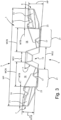
Figure 3 shows a second perspective view of the section ofFigure 1 , observed according to a direction more longitudinal to the longitudinal axis AXP of the profile itself; -
Figures 3A and 3B show an enlarged detail ofFigure 3 ; -
Figure 4 shows a perspective top view of a pallet obtained from the profile ofFigure 1 , according to a particular embodiment of the present invention; -
Figure 5 shows a perspective bottom view of the pallet ofFigure 4 ; -
Figure 6 shows an enlarged detail ofFigure 4 , depicting some elements in transparency; -
Figure 7 shows a perspective view of a connecting plinth of the pallet ofFigure 4 ; -
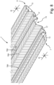
Figure 8 shows a first perspective view of a metal profile section according to a second particular embodiment of the present invention; -
Figure 9 shows a cross-section of the profile ofFigure 8 according to the ideal section plane IX-IX perpendicular to the axis of the profile itself; -
Figure 10 shows a plan view of the waived sheet layer or band from which the profile ofFigure 8 is obtained; -
Figure 11 shows a detail of the section ofFigure 9 ; -
Figure 12 shows an enlarged detail ofFigure 8 ; -
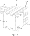
Figure 13 shows a perspective view of a pallet according to a third particular embodiment of the invention; -
Figure 13A shows a perspective view of a detail of a plinth and of the ends of the portions of some profile sections of the pallet ofFigure 13 ; -
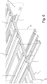
Figure 14 shows an axial view of two dismounted and stacked profile sections, usable to mount the pallet ofFigure 13 ; -
Figure 14A shows an enlarged detail of the two profile sections ofFigure 14 ; -
Figure 15 shows a partially sectional perspective view of a plinth and of the ends of the portions of some profile sections of the pallet ofFigure 13 , according to a section plane parallel to the longitudinal axis of some profile sections of the pallet; -
Figure 16 shows a lateral view of two pallets of the type ofFigure 13 , stacked on top of each other; -
Figure 17 shows a perspective bottom view of a plinth and a profile section of the pallet ofFigure 13 . -
Figures 1-3 ,3A, 3B show a metal profile according to a first particular embodiment of the present invention, denoted by theoverall reference - The
profile - The
profile - Such sheet can have thicknesses for example comprised between 0.2-2 millimetres, or between 0.3-1.5 millimetres, between 0.3-1.2 millimetres or between 0.45-0.6 millimetres.
- Preferably, the
profile - Such band can be deformed in a suitable roller machine, i.e., a profiling machine, provided with a plurality of rollers which progressively bend or otherwise deform the band advancing along the profiling machine itself.
- The roller axes can be for example substantially perpendicular to the advancing direction of the band in the profiling machine, which direction is parallel to the axis AXP of the
profile 1. - The sheet band forms the so-called main body of the
profile - The main body of the
profile major face 5 of the profile conventionally referred to as "ventral", wherein said major dorsal 3 and ventral 5 faces face two directions in space opposite to each other (Figure 3 ). - The
profile profile - Such cross-sections form two
lateral edges Figure 2 ,3 ). - At or near the two
lateral edges profile tubular portions - Each
tubular portion Figure 2 ,3 ), making theprofile Figure 3 ,3A , the longitudinal edges of the sheet band can be folded on more internal portions of the same band so as to form tubular, or otherwise closed, cross-sections; however in not-shown embodiments the tubular portions can be also made with one or more sheet strips not entirely folded on themselves, and for example wound in a spiral or in a relatively very close C-shape. - The
tubular portions profile profile pallet - Each
tubular portion profile 1 itself; in other words, in theprofile 1 the ratio WTB/WP is preferably less than or equal to 0.3. - More preferably the ratio WTB/WP is comprised between 0.15-0.27 times, and more preferably comprised between 0.18-0.25 times, between 0.19-0.23 times or between 0.19-0.21 times or approximately equal to 0.20 times.
- Preferably, the
central groove 15 forms a centrallongitudinal rib 16 on the majordorsal face 3 of theprofile Figure 3 ). - Preferably, the major
dorsal face 3 forms at least one - and more preferably at least two - connectingrecesses 18, each of which is located at one side of both a respectivetubular portion longitudinal rib 16. - More preferably each connecting
recess 18 is placed between a respectivetubular portion Figure 3 ). - For this purpose, each connecting
recess 18 can be delimited by a side of a respectivetubular portion central rib 16 and by the connectingportion 21. - Advantageously each
connecting recess 18 of afirst profile tubular portion second profile first profile dorsal faces 3 of the two profiles. - It is thus possible to catch and horizontally constrain several stacked pallets to each other, in which the
profile sections dorsal faces 3 to the outside of thepallet Figure 4 ,6 ,16 ), thus making the pallet stack much more solid and stable. - Alternatively to or in combination with the above, each
tubular portion profile 1 itself; in other words in theprofile 1 the ratio HTB/HP is preferably comprised between 0.5-1 times. - More preferably the ratio HTB/HP is comprised between 0.7-0.9 times, or between 0.80-0.85 times or between 0.83-0.84 times.
- Preferably, the cross-sections of the
tubular portions Figure 3 ) extends. - For this purpose, the ratio WTB/HTB between the maximum height and length of each
tubular portion - Preferably, the ratio RDST/WT between the square root RDST of the cross-sectional area of each
tubular portion profile 1 is comprised between 0.1-0.2 times, and more preferably comprised between 0.14-0.15 times or between 0.141-0.143 times and preferably equal to about 0.141 times. - The ratio RDST/HP between the square root RDST of the cross-sectional area of each
tubular portion profile 1 is preferably comprised between 0.8-1.3 times, and more preferably comprised between 0.9-0.97 times or between 0.95-0.96 times and preferably equal to about 0.958 times. - The ratio RDST/PRT between the square root RDST of the cross-sectional area of each
tubular portion tubular section - Preferably, each
tubular portion profile 1, for example by folding the sheet edge on one of the connectingportions 21 of the profile (Figure 3 ). - Preferably, the two sheet coats are subsequently clinched together, giving particular strength and deflection to the
profile 1; alternatively they can be for example rivetted, nailed, welded, brazed or screwed together. - The clinching points are preferably oblong in shape, for example in the form of straight lines.
- Preferably, at or near their centreline the cross-sections of the
profile 1 form a centrallongitudinal groove 15 on the major dorsal 3 or ventral 5 face which extends over at least half of the overall height HP of the profile, and more preferably at least on three quarters, four fifths or nine tenths of the overall height HP. - The central
longitudinal groove 15 as well as the potentiallateral grooves profile 1. - As in the embodiment of
Figure 1-3 thecentral groove 15 extends substantially over the entire height HP of theprofile 1. - If formed around its centreline by a single sheet layer, obviously if the portion of the
profile 1 forms a central groove on the majorventral face 5, it correspondingly forms a centrallongitudinal rib 16 on the major dorsal face 3 (Figure 3 ) and vice versa, if it forms a central longitudinal rib on the majorventral face 5 it correspondingly forms a central groove on the majordorsal face 3. - Preferably, the
central groove 15 at its deepest and innermost portion has a width WS1 less than or equal to 0.2 times the overall width WP of theprofile 1. - More preferably the ratio WS1/WP is comprised between 0.15-0.3 times, or between 0.13-0.2 times, between 0.13-0.15 times or approximately equal to 0.12 times.
- Such size of the width WS1 is more than enough to place the fixing
plinths 33 thereon. - The deepest and innermost portion of the
central groove 15 is preferably flat in shape (Figure 3 ). - Preferably, the
central groove 15 at its outermost portion has a width WS2 greater than or equal to 0.2 times the overall width WP of theprofile 1. - More preferably the ratio WS2/WP is comprised between 0.2-0.3 times, or between 0.23-0.35 times, between 0.23-0.27 times, between 0.22-0.24 times or approximately equal to 0.23 times.
- Preferably, the ratio WS2/WS1 is comprised between 1-2.5 times, and more preferably between 1.5-2 times, between 1.8-2 times, between 1.9-1.93 times and for example equal to 1.92 times.
- Preferably, the central
longitudinal groove 15 has sides substantially flared, tilted (Figure 3 ) or otherwise progressively widening ideally moving outwards from its deepest zone (Figure 3 ). - The sides of the central
longitudinal groove 15 have a tilt α [alfa], with respect to the direction along which the cross-sections of theprofile 1 extend overall, preferably comprised between 30-85° and more preferably between 40-70°, between 60-70°, between 63-68° or between 65°-68°. - Such tilts give the profile 1 a particular resistance to crushing.
- Advantageously the
profile 1 forms at least one laterallongitudinal groove profile 1 itself. - Each lateral
longitudinal groove - at one or more, or even all the
tubular portions 11; - in one or more, or even all the connecting
portions 21 of theprofile 1, where each connectingportion 21 extends between one of thetubular portions 11 and thecentral groove 15. - The sides of each lateral
longitudinal groove profile 1 extend overall, preferably comprised between 30-85° and more preferably between 40-70°, between 50-70°, between 55-65° or between 60°-70° (Figure 3A ). - Each lateral
longitudinal groove profile 1. - Each lateral
longitudinal groove profile 1; in other words, the ratio HL/HP is preferably comprised between 0.25-0.7 times, and more preferably comprised between 0.3-0.5 times, between 0.3-0.4 times, between 0.36-0.38 times and for example approximately equal to 0.36 times. - Each lateral
longitudinal groove profile 1; in other words the ratio WL/WP is preferably comprised between 0.02-0.1 times, and more preferably comprised between 0.04-0.09 times, between 0.05-0.08 times, between 0.06-0.08 times and for example approximately equal to 0.07 times. - The ratio HL/HP is preferably comprised between 0.2-0.8 times, and more preferably comprised between 0.3-0.6 times, between 0.3-0.4 times, between 0.35-0.45 times and for example equal to 0.36 times.
- The ratio WL/HL is preferably comprised between 0.3-1.7 times, and more preferably comprised between 0.4-1.5 times, between 0.7-1.4 times, between 1.1-1.4 times or between 1.3-1.4 times and for example equal to 1.34 times.
- The above-described lateral
longitudinal grooves profile - Advantageously at least one lateral
longitudinal groove tubular portion longitudinal groove tubular portion 11, 13 (Figure 3 ). - Advantageously at least one, and more preferably at least two lateral
longitudinal grooves Figure 3 ). - Advantageously at least one, and more preferably at least two lateral
longitudinal grooves Figure 3 ). - Preferably, the cross-sections of each
tubular portion Figure 3 ). - For this purpose, the cross-section of each
tubular portion proximal side 131 and adistal side 133 respectively arranged closer to and further from the central longitudinal groove 15 (Figure 3B ). - The proximal 131 and distal 133 sides can extend in a direction overall perpendicular or transverse to the direction along which the relative cross-section of the
profile 1 extends overall (Figure 3B ), although the proximal 131 and distal 133 sides are not necessarily flat in shape. - The ratio HTPX/THDX between the overall height HTPX of the
proximal side 131 and the overall height HTDX of thedistal side 133 is preferably comprised between 1.5-2.5 times, and more preferably comprised between 1.7-2.3 times, between 1.8-2.2 times or between 1.9-2.0 times and for example approximately equal to 1.93 times. - Advantageously the portion of the profile which connects each
tubular portion portion 21 forms astep 23 or other longitudinal prominence further strengthening theprofile longitudinal prominences 23 can be advantageously used to orderly stack (Figure 14, 14A ), grasp and handle the profile with automatic and non-automatic production equipment, or to align it, position it thereon or on templates or assembling jigs; in particular the steps or otherlongitudinal prominences 23 horizontally constrain pallets stacked on top of each other making the stack much more stable, safe and ordered. - The cross-sections of the
profile 1 are preferably symmetrical with respect to a plane passing through the longitudinal axis AXP of the profile itself and preferably perpendicular to the direction along which the cross-sections of theprofile 1 extend overall (Figure 2 ,3 ). - The major dorsal 3 and ventral 5 faces can form different width bearing surfaces, for example the major
dorsal face 3 can form a wider bearing surface than that formed by the major ventral face 5 (Figure 3 ). - Preferably, the sides and the surfaces of the
profile 1 are as possible devoid of holes and sheared zones, however they can have for example holes required for assembling different sections thereof to each other or with other components, or other preferably small openings, so as for example not to excessively reduce the structural resistance of theprofile 1. - The holes or other shears accommodating the nails, screws, or rivets or more generally serving to fix the
various profile sections 1 composing thepallet -
Figures 4-7 and 13-17 show respectively a first and a second examples of pallet - i.e., bench - obtainable with theprofile 1. - Such pallet, denoted by the
overall reference profile sections 1 arranged so as to form several rows of sections parallel or otherwise placed side by side to each other. - The
pallet profile sections - The upper loading platform preferably comprises a second row or other second group of
profile sections sections 1A. - Advantageously the
profile sections pallet dorsal face 3. - Preferably, the
pallet profile sections sections 1A. - The base preferably comprises a plurality of fixing
plinths 33 obtained for example such as sheet boxes (Figure 7 ), squat tubular sheet sections (Figure 7 ) (or even blocks made of plastic, wood, or other non-metallic materials). - Each fixing
plinth 33 can be for example substantially cubic, or otherwise preferably squat, in overall shape (Figure 7 ). - Each fixing
plinth 33 can be obtained for example by bending and folding on itself a sheet layer suitably sheared or otherwise cut. - Each fixing
plinth 33 can be made of a sheet of thickness greater than or equal to the sheet thesections - Preferably, for this purpose the sides of the fixing
plinth 33 surround, or otherwise extend around, a main loading axis AXZ, which is, during the normal use, preferably substantially parallel to the vertical axis or otherwise to the main loading direction of the pallet or is substantially perpendicular to the surface in which the upper loading platform of thepallet - Advantageously the edges of the open ends of the fixing
plinth 33 form a plurality ofaxial protrusions 330 and a plurality ofaxial recesses 331, which extend or otherwise lie in surfaces parallel or otherwise longitudinal to the main loading axis AXZ of theplinth 33. - Advantageously the edges of the open ends of the fixing
plinth 33 form one or more fixingprotrusions 332, each of which is arranged to be fixed - for example through riveting, gluing, or welding - to aprofile section - Preferably, at least some of the fixing
protrusions 332 extend or otherwise lie in surfaces substantially perpendicular or transverse to the main loading axis AXZ (Figure 7 ), allowing to place and firmly fix through rivets, screws or welding theprofile sections - Each fixing
plinth 33 preferably fixes threedifferent profile sections 1 pertaining to the three above-mentioned and different groups of sections: thegroup sections - The
profile sections 1A of the first group or the first row can for example rest on theprofile sections 1B of the second group or the second row. - The
profile sections 1A of the first group or the first row and/or theprofile sections 1B of the second group or the second row can rest on a first end of the fixingplinths 33. - The
profile sections 1C of the third group are preferably spaced apart from thesections plinths 33, so as to lift and move away from the ground, floor or moisture the goods placed on the upper loading platform of thepallet 30, preferably forming together with thesections 1C of the base suitable openings arranged to accommodate the forks of a lift truck, a crane, a mechanical arm or other lifting device. - The
various profile sections plinths 33 through screws, nails, rivets, welding, clinching, sheet metal flaps, welded or glued. - The
pallet 30 is particularly simple and inexpensive to assemble, since it can be indeed assembled by simply sawing thesections plinths 30 through extremely simple and inexpensive techniques such as screwing, riveting, or welding. - Advantageously the
profile sections pallet 30 are substantially straight and are not particularly bent so as their axis AXP has different orientations and tilts in space in the various lines of the same section. - Therefore, it is very simple and inexpensive to make small workstations producing and assembling the
pallet 30 near the final users thereof, i.e., the producers of the most different goods to be loaded and packed on thepallet 30, in order not to transport already finished bulky loads of pallets up to the final users, as well as it is also very inexpensive to set the workstations to assemble thepallets 30 directly in the production plants of the final users thereof. - Once cut by a simple sawing machine, the
sections - The
pallet 30 is suitable to be produced both manually and by highly automatized and high-productivity plants. - The straight and otherwise very simple shape of the profile sections composing the
pallet 30 and their assembling through nails, screws, rivets, clinching and other above-mentioned fixing systems allow to very easily and quickly repair the pallet 30 - in order to dismount it, dismounting nails, screws or rivets can be enough - allowing to reuse it many times remarkably extending the service life and thus the acquisition and operating costs thereof and remarkably reducing the environmental pollution. - Therefore, the
pallet 30 described above satisfies very well the requirement of having easily repairable pallets; the extent to which this requirement is popular is proven by the way by the rich and thriving network of companies and laboratories collecting, repairing and reselling used wood pallets in Europe: it is a very active field which remarkably contributes to reduce the economic and ecologic costs of the logistic and transporting activities. - On the other hand, the difficulty of repair is a big drawback of plastic material pallets, mostly used in some fields, such as for example food or pharmaceutical industry, in which some of the advantages thereof, such as the ease of washing and disinfecting, become relevant such as to compensate the difficulty of repair.
- When they can no longer be repaired, the
pallets 30 can be for example remelted. - The above-described exemplary embodiments are subject to different modifications and variations while not departing from the scope of protection of the present invention.
- For example, the central
longitudinal groove 15 as well as the potentiallateral grooves - As for example in the embodiment of
Figure 4 ,5 the upper loading platform of thepallet 30 can comprise for example a first row or first group of fiveprofile sections profile sections 1B of the second group; the base of thepallet 30 can further comprise for example threeprofile sections 1C of the third group or the third row; however, in not-shown embodiments of a pallet according to the invention, the loading platform and the base can also comprise numbers ofprofile sections Figure 4 ,5 , for example two, three, four, six, seven, eight, nine, ten or even more sections. - The
profile sections - The cross-sections of the
tubular portions - As for example in the embodiment of
Figure 8 a profile 1' according to the invention can be obtained by bending - for example in a profiling line - not only a substantially flat sheet layer or band but also sheet layers or bands from the ribbed surface or on which suitable embossments and cavities have been formed, for example through rolling and/or drawing and/or scuffing performed by a scuffing machine. - Advantageously the profile 1' can be obtained by the following operations:
- S.1) forming a plurality of ridges (900) extending parallel or otherwise substantially placed side by side to each other on a sheet, where at least part of the ridges (900) change direction forming on the sheet at least one first substantially acute angle (γ [gamma]);
- S.2) bending the sheet so as to form at least two lateral faces (500) and at least a corner fold (700) connecting the lateral faces (500) and being placed therebetween, so that:
- the corner fold (700) and the at least two lateral faces (5) extend longitudinally with respect to the profile (1');
- the vertex of the at least one first substantially acute angle (γ [gamma]) is at least at one of the corner folds (700);
- the line of such ridges (900) closest to a corner fold (700) is oblique with respect to such corner fold (700), where such obliquity is referred to a second and third angles (ϕ, ψ [phi, psi]) the ridges (900) and the corner fold (700) form one of the lateral faces (500).
- Preferably, the profile 1' is obtained by the following operations:
- S.3) forming a plurality of throats (1100) on the sheet so that:
- the ridges (900) and the throats (1100) extend parallel or otherwise substantially placed side by side to each other;
- a plurality of ridges (900) are flanked each on both sides by at least a pair of throats (1100);
- a plurality of throats (1100) are flanked each on both sides by at least a pair of ridges (900);
- at least part of the ridges (900) and of the throats (1100) change direction also forming on the sheet at least the first substantially acute angle (γ [gamma]);
- S.4) bending the sheet so as to form the lateral edges (7, 9), the tubular portions (11, 13) and the central longitudinal groove (15).
- The operation S.4) can be performed for example through the above-mentioned roller machine, i.e., scuffing machine.
- Preferably, the first substantially acute angle (γ [gamma]) is less than or equal to 90°.
- Preferably, at least one of the second and the third angles (ϕ, ψ [phi, psi]) is less than or equal to 45°, 35°, 30° and still more preferably comprised between 5°-25°.
- Preferably, the first angle γ [gamma] formed by the
ridges 900 before the operation S.4) is approximately equal to the sum of the second and third angles ϕ, ψ [phi, psi]. - Preferably, the height HC of the ridges (900) measured with respect to the bottom of the two throats (1100) adjacent thereto is comprised between 0.2-2 millimetres and/or between 0.5-4 times the thickness SL of the sheet.
- Preferably, the pitch of the ridges PC is comprised between 2-40 millimetres and/or between 2-40 times the thickness SL of the sheet.
- Preferably, the ridges (900) and the throats (1100) follow V-shaped or zig-zag paths on the profile 1'.
- Preferably, all the
ridges 900 change direction forming on the sheet layer or band at least the first substantially acute angle γ [gamma]. - Preferably, as shown in
Figures 8-12 , the profile 1' forms a plurality of substantially acute angles γ [gamma] whose vertexes are aligned on one or more rows preferably straight and parallel, or otherwise longitudinal to the profile 1' itself. - Advantageously the ends of the
metal profile 1", 1A", 1B", 1C" form one or more check strips 25, 27, 29 preferably obtained by bending the sheet which forms the profile itself (Figure 13 ,13A ,14, 14A ). - In the mounted
pallet 30" the check strips 25, 27, 29 are advantageously arranged to extend around and cover at least some lines of the edges of a respective fixing plinth 33 (Figure 13 ,13A ). - In the mounted
pallet 30" the check strips 25, 27, 29 advantageously rest - or are arranged for this purpose - against one or more portions of the edges of arespective fixing plinth 33, more preferably against one or more axial protrusions 330 (Figure 13 ,13A ). - Advantageously the check strips 25, 27, 29 are arranged to rest against the one or more
axial protrusions 330 in a direction parallel and/or perpendicular - and more preferably in both said directions - to the surface in which suchaxial protrusions 330 substantially lie. - Advantageously the ends of the
metal profile 1", 1A", 1B", 1C" form one ormore recesses respective fixing plinth 33, accommodating transversally such edges of the plinth 33 so as to prevent or otherwise limit the deflections of such edges of the plinth 33 towards both the inside and the outside of the plinth 33 itself (Figure 13A ). - Thereby, the ends of the
metal profile sections 1A", 1B", 1C" almost eliminate, or otherwise remarkably limit the deflection deformations and the lateral protrusions of the check strips 25, 27, 29 and more generally of the lateral walls of the fixingplinths 33, causing the sheet of theplinths 33 to be mostly or otherwise largely compression-stressed and stiffening and thus remarkably increasing the resistance to compression of theplinths 33 and of theentire pallet 30"; in particular the sheet of theplinths 33 can be mostly or otherwise largely compression-stressed when transmitting the push of the floor on which thepallet 30 rests to themetal profile sections 1A", 1B", 1C", and vice versa when transmitting the pressure of themetal profile sections 1A", 1B", 1C" on the floor on which thepallet 30 rests. - Due to the above measures, the
pallet 30" is able to support vertical compression and deflection loads, when lifted on the forks of a lift truck equal to equivalent much heavier wooden - for example so-called EPAL - or plastic pallets. - Indeed, it has been found that the
pallet 30" can have a weight approximately equal to two thirds of the weight of a wooden pallet having the same resistance to compression and deflection, and approximately half the weight of a plastic material pallet having the same resistance to compression and deflection. - The values of resistance to compression and deflection of the
pallet 30" and of the wooden and plastic material pallets have been obtained testing them according to UNI EN ISO 8611 norm and respectively correspond to the resistance to the static vertical load and to the ensured dynamic (vertical) load defined by such norm. - The check strips 25, 27, 29 remarkably reduce the sharp edges of both the
metal profile sections 1A", 1B", 1C" and the fixingplinths 33 remarkably reducing the risk of injury by handling the pallet for the workers, equally facilitating and accelerating the moving of thepallet 30". - Advantageously the fixing
plinth 33 is provided, in what is its bottom part during the normal use, with one ormore fixing tabs 31 each of which is folded toward the inside of the plinth 33 itself and fixed for example by welding, one ormore screws 35 or one or more rivets, at the sides of ametal profile section 1A", 1B", 1C" (Figure 13 ). - The
tab 31 can be placed on a portion of a side of theprofile section 1A", 1B", 1C". - Fixing the
tab 31 avoids the sliding of theprofile section 1A", 1B", 1C" with respect to the plinth 33 when thepallet 30" is deflection-stressed, for example in the dynamic resistance test according the above-mentioned UNI EN ISO 8611 norm, stiffening and remarkably increasing the resistance of thepallet 30"; remarkably strengthening the assembly of the two; the author of the present invention has been able to obtain up to 50% increases of the resistance to dynamic load and a comparable reduction, i.e., around 50%, of the deflection. - Each fixing
tab 31 can be more or less wide and be fixed to therelative profile section - Preferably, the various fixing
protrusions 332 of a plinth 33 allows the latter to be fixed at or near the lateral - i.e., longitudinal - edges of ametal profile section 1A", 1B", 1C", and more preferably through at least two - and more preferably at least three - screws, rivets 35 or welding ribbons or points for each lateral edge of themetal profile section 1A", 1B", 1C" (Figure 15 ,17 ), contributing to remarkably strengthen thepallet 30". - The rivets facilitate the assembling automatization of the
pallet 30" in addition to ensuring a better endurance of the connections. - Advantageously in the
metal profile sections Figure 17 ).
Preferably the drain holes 37 are arranged at the fixingplinths 33 so as to allow water to outflow from the inside of the plinths 33 (Figure 17 ). - Each reference in this disclosure to "an embodiment", "an exemplary embodiment" means that a particular feature or structure described in connection with such embodiment is comprised in at least one embodiment of the invention is comprised in at least one embodiment of the invention and in particular in a particular variation of the invention as defined in a main claim.
- The fact that such expressions occur in various steps of the disclosure does not mean that they are necessarily referred only to the same embodiment.
- Further, when a feature, element, or structure is described in connection with a particular embodiment, it is observed that applying such feature, element, or structure to other embodiments falls within the competence of those skilled in the art.
- Numerical references differing only by different single quote marks, e.g., 21', 21", 21‴, when not otherwise specified denote different variations of an element referred to in the same manner.
- Further, all the details are replaceable by technically equivalent elements.
- For example, the materials used, as well as the size, can be any depending on the technical requirements.
- It should be understood that an expression such as "A comprises B, C, D" or "A is formed by B, C, D" comprises and also describes the particular case wherein "A consists of B, C, D".
- The expression "A comprises an element B" unless otherwise specified is to be understood as "A comprises one or more elements B".
- References to a "first, second, third, ... nth entity" only aim to distinguish them from each other but the indication of the nth entity does not necessarily mean the existence of the first, second, ... (n-1)th entity.
- The examples and lists of possible variations of the present application are to be intended as nonexhaustive lists.
Claims (15)
- Metal profile (1, 1A, 1B, 1C) comprising a main body obtained by bending a metal sheet forming a first major face (3) conventionally referred to as "dorsal" and a second major face (5) of the profile conventionally referred to as "ventral", wherein said major dorsal (3) and ventral (5) faces face two directions in space opposite to each other, and wherein:- the profile (1, 1A, 1B, 1C) forms substantially oblong cross-sections which form two lateral edges (7, 9), each of which is placed at a respective end of these cross-sections;- at or near the two lateral edges (7, 9) the profile (1) forms two respective tubular portions (11, 13), each of which is substantially tubular in shape;- each tubular portion (11, 13) has a maximum width (WTB) less than or equal to 0.3 times the overall length (WP) of the cross-sections of the profile (1) itself; and/or- each tubular portion (11, 13) has a maximum height (HTB) substantially comprised between 0.5-1 times the maximum height (HP) of the cross-sections of the profile (1) itself; and further- at or near their centreline the cross-sections of the profile (1) form a central longitudinal groove (15) on the major dorsal (3) or ventral (5) face which extends over at least half of the overall height (HP) of the profile (1).
- Profile (1) according to claim 1, the cross-sections of which are substantially symmetrical with respect to an ideal plane passing through the longitudinal axis (AXP) of the profile (1) itself.
- Profile (1) according to claim 1 or 2, the cross-sections of which are substantially oblong in shape.
- Profile (1) according to one or more preceding claims, wherein the central longitudinal groove (15) extends over the entire overall height (HP) of the profile (1).
- Profile (1) according to one or more preceding claims, wherein the maximum width (WTB) of each tubular portion (11, 13) is greater than or equal to 0.15 times the overall length (WP) of the cross-sections of the profile (1) itself.
- Profile (1) according to one or more preceding claims, wherein at least in some of its cross-sections at least one lateral longitudinal groove (17, 19) is formed which extends parallel or in any case longitudinally to the axis (AXP) of the profile (1) itself and is arranged in one or more of the following positions:- at least at one of the tubular portions (11, 13);- in at least one connecting portion (21) of the profile extending between one of the tubular portions (11, 13) and the central longitudinal groove (15).
- Profile according to claim 6, wherein each lateral longitudinal groove (17, 19) has one or more of the following features:- a maximum depth (HL) comprised between 0.25-0.7 times the maximum height (HP) of the profile;- a maximum width (WL) comprised between 0.02-0.1 times the overall width (WP) of the profile (1);- a ratio (WL/HL) between the maximum width (WL) and the maximum depth (HL) comprised between 0.3-1.7 times.
- Profile according to one or more preceding claims, wherein the ratio (RDST/WT) between the square root (RDST) of the cross-sectional area of each tubular portion (11, 13) and the overall width (WP) of the profile 1 is comprised between 0.1-0.2 times.
- Profile according to one or more preceding claims, wherein the ratio (RDST/WT) between the square root (RDST) of the cross-sectional area of each tubular portion (11, 13) and the overall width (WP) of the profile 1 is comprised between 0.141-0.143 times.
- Profile according to one or more preceding claims, wherein the ratio (RDST/HP) between the square root (RDST) of the cross-sectional area of each tubular portion (11, 13) and the maximum height (HP) of the profile 1 is comprised between 0.8-1.3 times.
- Profile according to one or more preceding claims, wherein the ratio (RDST/HP) between the square root (RDST) of the cross-sectional area of each tubular portion (11, 13) and the maximum height (HP) of the profile 1 is comprised between 0.95-0.96 times.
- Pallet (30, 30") for packaging, moving, and transporting goods comprising a plurality of sections of the profile (1) according to one or more of claims 1-11.
- Pallet (30, 30") according to claim 12, wherein the profile sections (1) form several rows and the sections (1) of each row are arranged substantially parallel or otherwise flanked to each other.
- Pallet (30, 30") according to claim 12 or 13, wherein:- the profile sections (1) form at least three rows;- a first row of sections (1A) forms a loading platform on which to place the goods to be packaged, moved and/or transported;- a third row of sections (1C) forms a base through which the pallet (30) can rest on a floor, ground, shelf, or other support;- a second row of sections (1B) is placed between the first row (1A) and the third row of sections (1C);- the sections of one of the three rows are perpendicular or otherwise transverse to the sections of at least another of the three rows of sections.
- Pallet (30, 30") according to one or more of claims 12 to 14, comprising a plurality of fixing plinths (33) for fixing and connecting the plurality of profile sections (1, 1A, 1B, 1C) to each other, and the fixing plinths (33) are fixed to one or more profile sections (1, 1A, 1B, 1C) by one or more of the following systems: screws, screwing, rivets, nails, clinching, sheet metal flaps, gluing, welding, brazing, plastic co-moulding.
Priority Applications (2)
| Application Number | Priority Date | Filing Date | Title |
|---|---|---|---|
| RS20250607A RS66931B1 (en) | 2022-02-16 | 2023-02-15 | Metal profile, pallet and associated manufacturing process |
| HRP20250737TT HRP20250737T1 (en) | 2022-02-16 | 2023-02-15 | METAL PROFILE, PALLET AND CORRESPONDING PRODUCTION PROCESS |
Applications Claiming Priority (1)
| Application Number | Priority Date | Filing Date | Title |
|---|---|---|---|
| IT202200002837 | 2022-02-16 |
Publications (3)
| Publication Number | Publication Date |
|---|---|
| EP4230546A1 true EP4230546A1 (en) | 2023-08-23 |
| EP4230546C0 EP4230546C0 (en) | 2025-04-02 |
| EP4230546B1 EP4230546B1 (en) | 2025-04-02 |
Family
ID=81392636
Family Applications (1)
| Application Number | Title | Priority Date | Filing Date |
|---|---|---|---|
| EP23156716.5A Active EP4230546B1 (en) | 2022-02-16 | 2023-02-15 | Metal profile, pallet and associated manufacturing process |
Country Status (6)
| Country | Link |
|---|---|
| EP (1) | EP4230546B1 (en) |
| ES (1) | ES3033117T3 (en) |
| HR (1) | HRP20250737T1 (en) |
| HU (1) | HUE072070T2 (en) |
| PL (1) | PL4230546T3 (en) |
| RS (1) | RS66931B1 (en) |
Citations (6)
| Publication number | Priority date | Publication date | Assignee | Title |
|---|---|---|---|---|
| DE4114888A1 (en) * | 1991-05-07 | 1993-01-28 | Schleicher Sigrid | Load handling pallet assembly - is made from corrugated strips with hollow sections for extra strength |
| US5367960A (en) * | 1992-11-02 | 1994-11-29 | Sigrid Schleicher | Four-way sheet metal pallet |
| CN2509097Y (en) * | 2001-10-31 | 2002-09-04 | 杨振宇 | Pallet |
| ITPN20040037A1 (en) | 2004-05-21 | 2004-08-21 | Andrea Tonet | METALLIC PALLET |
| KR200417384Y1 (en) | 2006-02-02 | 2006-05-26 | 주식회사 진데크 | Frame structure of steel pallet |
| WO2015025210A1 (en) * | 2013-08-23 | 2015-02-26 | Roberto Pisano | Metal pallet with assemblable components |
-
2023
- 2023-02-15 HR HRP20250737TT patent/HRP20250737T1/en unknown
- 2023-02-15 ES ES23156716T patent/ES3033117T3/en active Active
- 2023-02-15 HU HUE23156716A patent/HUE072070T2/en unknown
- 2023-02-15 EP EP23156716.5A patent/EP4230546B1/en active Active
- 2023-02-15 PL PL23156716.5T patent/PL4230546T3/en unknown
- 2023-02-15 RS RS20250607A patent/RS66931B1/en unknown
Patent Citations (6)
| Publication number | Priority date | Publication date | Assignee | Title |
|---|---|---|---|---|
| DE4114888A1 (en) * | 1991-05-07 | 1993-01-28 | Schleicher Sigrid | Load handling pallet assembly - is made from corrugated strips with hollow sections for extra strength |
| US5367960A (en) * | 1992-11-02 | 1994-11-29 | Sigrid Schleicher | Four-way sheet metal pallet |
| CN2509097Y (en) * | 2001-10-31 | 2002-09-04 | 杨振宇 | Pallet |
| ITPN20040037A1 (en) | 2004-05-21 | 2004-08-21 | Andrea Tonet | METALLIC PALLET |
| KR200417384Y1 (en) | 2006-02-02 | 2006-05-26 | 주식회사 진데크 | Frame structure of steel pallet |
| WO2015025210A1 (en) * | 2013-08-23 | 2015-02-26 | Roberto Pisano | Metal pallet with assemblable components |
Also Published As
| Publication number | Publication date |
|---|---|
| PL4230546T3 (en) | 2025-09-08 |
| HRP20250737T1 (en) | 2025-08-15 |
| HUE072070T2 (en) | 2025-10-28 |
| EP4230546C0 (en) | 2025-04-02 |
| EP4230546B1 (en) | 2025-04-02 |
| ES3033117T3 (en) | 2025-07-30 |
| RS66931B1 (en) | 2025-07-31 |
Similar Documents
| Publication | Publication Date | Title |
|---|---|---|
| RU2689965C2 (en) | Structural element | |
| JP3369172B2 (en) | Corrugated pallets | |
| US5584951A (en) | Method of making a beam pallet | |
| EP1819599B1 (en) | Pallet for storing and transporting goods | |
| CN103732503B (en) | Load structure | |
| US9751657B2 (en) | Material handling pallet | |
| US6539880B2 (en) | Corrugated paperboard pallet rail | |
| WO2009029988A1 (en) | Steel strips with folded edges to form load bearing structure | |
| US20100107936A1 (en) | Pallet for storing and transporting goods | |
| EP4230546B1 (en) | Metal profile, pallet and associated manufacturing process | |
| WO1990003921A1 (en) | Support member | |
| US20210139195A1 (en) | Pallet | |
| CN206202916U (en) | Metal tray | |
| EP2377768B1 (en) | Packing system | |
| GB2454529A (en) | Pallet for sheets of glass | |
| CN220392004U (en) | Bracket | |
| KR20050040658A (en) | Steel pallet | |
| FI75391C (en) | BYGGNADSELEMENT AV METALL OCH ANVAENDANDET AV DET. | |
| JP2637668B2 (en) | Nested rack using special steel bar | |
| WO2025032118A1 (en) | Paperboard pallet and apparatus for producing such a pallet | |
| AU776023B2 (en) | A pallet | |
| HK40020943A (en) | Structural element | |
| HK40020943B (en) | Structural element | |
| AU4335989A (en) | Support member | |
| JPH09191952A (en) | Special Λ shaped steel |
Legal Events
| Date | Code | Title | Description |
|---|---|---|---|
| REG | Reference to a national code |
Ref country code: HR Ref legal event code: TUEP Ref document number: P20250737T Country of ref document: HR |
|
| PUAI | Public reference made under article 153(3) epc to a published international application that has entered the european phase |
Free format text: ORIGINAL CODE: 0009012 |
|
| STAA | Information on the status of an ep patent application or granted ep patent |
Free format text: STATUS: THE APPLICATION HAS BEEN PUBLISHED |
|
| AK | Designated contracting states |
Kind code of ref document: A1 Designated state(s): AL AT BE BG CH CY CZ DE DK EE ES FI FR GB GR HR HU IE IS IT LI LT LU LV MC ME MK MT NL NO PL PT RO RS SE SI SK SM TR |
|
| STAA | Information on the status of an ep patent application or granted ep patent |
Free format text: STATUS: REQUEST FOR EXAMINATION WAS MADE |
|
| 17P | Request for examination filed |
Effective date: 20240222 |
|
| RBV | Designated contracting states (corrected) |
Designated state(s): AL AT BE BG CH CY CZ DE DK EE ES FI FR GB GR HR HU IE IS IT LI LT LU LV MC ME MK MT NL NO PL PT RO RS SE SI SK SM TR |
|
| STAA | Information on the status of an ep patent application or granted ep patent |
Free format text: STATUS: EXAMINATION IS IN PROGRESS |
|
| 17Q | First examination report despatched |
Effective date: 20240603 |
|
| GRAP | Despatch of communication of intention to grant a patent |
Free format text: ORIGINAL CODE: EPIDOSNIGR1 |
|
| STAA | Information on the status of an ep patent application or granted ep patent |
Free format text: STATUS: GRANT OF PATENT IS INTENDED |
|
| GRAS | Grant fee paid |
Free format text: ORIGINAL CODE: EPIDOSNIGR3 |
|
| INTG | Intention to grant announced |
Effective date: 20250109 |
|
| GRAA | (expected) grant |
Free format text: ORIGINAL CODE: 0009210 |
|
| STAA | Information on the status of an ep patent application or granted ep patent |
Free format text: STATUS: THE PATENT HAS BEEN GRANTED |
|
| AK | Designated contracting states |
Kind code of ref document: B1 Designated state(s): AL AT BE BG CH CY CZ DE DK EE ES FI FR GB GR HR HU IE IS IT LI LT LU LV MC ME MK MT NL NO PL PT RO RS SE SI SK SM TR |
|
| REG | Reference to a national code |
Ref country code: GB Ref legal event code: FG4D |
|
| REG | Reference to a national code |
Ref country code: CH Ref legal event code: EP |
|
| REG | Reference to a national code |
Ref country code: DE Ref legal event code: R096 Ref document number: 602023002643 Country of ref document: DE |
|
| REG | Reference to a national code |
Ref country code: IE Ref legal event code: FG4D |
|
| U01 | Request for unitary effect filed |
Effective date: 20250411 |
|
| U07 | Unitary effect registered |
Designated state(s): AT BE BG DE DK EE FI FR IT LT LU LV MT NL PT RO SE SI Effective date: 20250422 |
|
| REG | Reference to a national code |
Ref country code: ES Ref legal event code: FG2A Ref document number: 3033117 Country of ref document: ES Kind code of ref document: T3 Effective date: 20250730 |
|
| REG | Reference to a national code |
Ref country code: HR Ref legal event code: T1PR Ref document number: P20250737 Country of ref document: HR |
|
| REG | Reference to a national code |
Ref country code: GR Ref legal event code: EP Ref document number: 20250401166 Country of ref document: GR Effective date: 20250707 |
|
| REG | Reference to a national code |
Ref country code: SK Ref legal event code: T3 Ref document number: E 46756 Country of ref document: SK |
|
| PG25 | Lapsed in a contracting state [announced via postgrant information from national office to epo] |
Ref country code: IS Free format text: LAPSE BECAUSE OF FAILURE TO SUBMIT A TRANSLATION OF THE DESCRIPTION OR TO PAY THE FEE WITHIN THE PRESCRIBED TIME-LIMIT Effective date: 20250802 |
|
| REG | Reference to a national code |
Ref country code: HU Ref legal event code: AG4A Ref document number: E072070 Country of ref document: HU |
|
| PG25 | Lapsed in a contracting state [announced via postgrant information from national office to epo] |
Ref country code: SM Free format text: LAPSE BECAUSE OF FAILURE TO SUBMIT A TRANSLATION OF THE DESCRIPTION OR TO PAY THE FEE WITHIN THE PRESCRIBED TIME-LIMIT Effective date: 20250402 |
|
| PGFP | Annual fee paid to national office [announced via postgrant information from national office to epo] |
Ref country code: MK Payment date: 20251219 Year of fee payment: 4 |
|
| U20 | Renewal fee for the european patent with unitary effect paid |
Year of fee payment: 4 Effective date: 20251211 |
|
| PGFP | Annual fee paid to national office [announced via postgrant information from national office to epo] |
Ref country code: IE Payment date: 20251209 Year of fee payment: 4 |
|
| PGFP | Annual fee paid to national office [announced via postgrant information from national office to epo] |
Ref country code: PL Payment date: 20251128 Year of fee payment: 4 |
|
| PLBE | No opposition filed within time limit |
Free format text: ORIGINAL CODE: 0009261 |
|
| STAA | Information on the status of an ep patent application or granted ep patent |
Free format text: STATUS: NO OPPOSITION FILED WITHIN TIME LIMIT |
|
| REG | Reference to a national code |
Ref country code: CH Ref legal event code: L10 Free format text: ST27 STATUS EVENT CODE: U-0-0-L10-L00 (AS PROVIDED BY THE NATIONAL OFFICE) Effective date: 20260211 |
|
| REG | Reference to a national code |
Ref country code: HR Ref legal event code: ODRP Ref document number: P20250737 Country of ref document: HR Payment date: 20251223 Year of fee payment: 4 |
|
| REG | Reference to a national code |
Ref country code: CH Ref legal event code: U11 Free format text: ST27 STATUS EVENT CODE: U-0-0-U10-U11 (AS PROVIDED BY THE NATIONAL OFFICE) Effective date: 20260301 |
|
| 26N | No opposition filed |
Effective date: 20260105 |
|
| PGFP | Annual fee paid to national office [announced via postgrant information from national office to epo] |
Ref country code: HU Payment date: 20260122 Year of fee payment: 4 |
|
| PGFP | Annual fee paid to national office [announced via postgrant information from national office to epo] |
Ref country code: ES Payment date: 20260310 Year of fee payment: 4 |
|
| PGFP | Annual fee paid to national office [announced via postgrant information from national office to epo] |
Ref country code: NO Payment date: 20260211 Year of fee payment: 4 |
|
| PGFP | Annual fee paid to national office [announced via postgrant information from national office to epo] |
Ref country code: HR Payment date: 20260120 Year of fee payment: 4 |
|
| PGFP | Annual fee paid to national office [announced via postgrant information from national office to epo] |
Ref country code: RS Payment date: 20260116 Year of fee payment: 4 |
|
| PGFP | Annual fee paid to national office [announced via postgrant information from national office to epo] |
Ref country code: TR Payment date: 20260211 Year of fee payment: 4 |
|
| PGFP | Annual fee paid to national office [announced via postgrant information from national office to epo] |
Ref country code: CH Payment date: 20260301 Year of fee payment: 4 Ref country code: CZ Payment date: 20260130 Year of fee payment: 4 |
|
| PGFP | Annual fee paid to national office [announced via postgrant information from national office to epo] |
Ref country code: GR Payment date: 20260114 Year of fee payment: 4 |
|
| PGFP | Annual fee paid to national office [announced via postgrant information from national office to epo] |
Ref country code: SK Payment date: 20260113 Year of fee payment: 4 |
|
| PGFP | Annual fee paid to national office [announced via postgrant information from national office to epo] |
Ref country code: AL Payment date: 20260210 Year of fee payment: 4 |