EP4230523B1 - Tiltrotor aircraft - Google Patents
Tiltrotor aircraft Download PDFInfo
- Publication number
- EP4230523B1 EP4230523B1 EP23171219.1A EP23171219A EP4230523B1 EP 4230523 B1 EP4230523 B1 EP 4230523B1 EP 23171219 A EP23171219 A EP 23171219A EP 4230523 B1 EP4230523 B1 EP 4230523B1
- Authority
- EP
- European Patent Office
- Prior art keywords
- aircraft
- propulsion systems
- wing
- mode
- pair
- Prior art date
- Legal status (The legal status is an assumption and is not a legal conclusion. Google has not performed a legal analysis and makes no representation as to the accuracy of the status listed.)
- Active
Links
Images







Classifications
-
- B—PERFORMING OPERATIONS; TRANSPORTING
- B64—AIRCRAFT; AVIATION; COSMONAUTICS
- B64C—AEROPLANES; HELICOPTERS
- B64C29/00—Aircraft capable of landing or taking-off vertically, e.g. vertical take-off and landing [VTOL] aircraft
- B64C29/0008—Aircraft capable of landing or taking-off vertically, e.g. vertical take-off and landing [VTOL] aircraft having its flight directional axis horizontal when grounded
- B64C29/0016—Aircraft capable of landing or taking-off vertically, e.g. vertical take-off and landing [VTOL] aircraft having its flight directional axis horizontal when grounded the lift during taking-off being created by free or ducted propellers or by blowers
- B64C29/0033—Aircraft capable of landing or taking-off vertically, e.g. vertical take-off and landing [VTOL] aircraft having its flight directional axis horizontal when grounded the lift during taking-off being created by free or ducted propellers or by blowers the propellers being tiltable relative to the fuselage
-
- B—PERFORMING OPERATIONS; TRANSPORTING
- B64—AIRCRAFT; AVIATION; COSMONAUTICS
- B64C—AEROPLANES; HELICOPTERS
- B64C13/00—Control systems or transmitting systems for actuating flying-control surfaces, lift-increasing flaps, air brakes, or spoilers
- B64C13/24—Transmitting means
-
- B—PERFORMING OPERATIONS; TRANSPORTING
- B64—AIRCRAFT; AVIATION; COSMONAUTICS
- B64C—AEROPLANES; HELICOPTERS
- B64C23/00—Influencing air flow over aircraft surfaces, not otherwise provided for
- B64C23/06—Influencing air flow over aircraft surfaces, not otherwise provided for by generating vortices
- B64C23/065—Influencing air flow over aircraft surfaces, not otherwise provided for by generating vortices at the wing tips
- B64C23/069—Influencing air flow over aircraft surfaces, not otherwise provided for by generating vortices at the wing tips using one or more wing tip airfoil devices, e.g. winglets, splines, wing tip fences or raked wingtips
- B64C23/072—Influencing air flow over aircraft surfaces, not otherwise provided for by generating vortices at the wing tips using one or more wing tip airfoil devices, e.g. winglets, splines, wing tip fences or raked wingtips the wing tip airfoil devices being moveable in their entirety
-
- B—PERFORMING OPERATIONS; TRANSPORTING
- B64—AIRCRAFT; AVIATION; COSMONAUTICS
- B64C—AEROPLANES; HELICOPTERS
- B64C27/00—Rotorcraft; Rotors peculiar thereto
- B64C27/22—Compound rotorcraft, i.e. aircraft using in flight the features of both aeroplane and rotorcraft
- B64C27/28—Compound rotorcraft, i.e. aircraft using in flight the features of both aeroplane and rotorcraft with forward-propulsion propellers pivotable to act as lifting rotors
-
- B—PERFORMING OPERATIONS; TRANSPORTING
- B64—AIRCRAFT; AVIATION; COSMONAUTICS
- B64C—AEROPLANES; HELICOPTERS
- B64C3/00—Wings
- B64C3/38—Adjustment of complete wings or parts thereof
-
- B—PERFORMING OPERATIONS; TRANSPORTING
- B64—AIRCRAFT; AVIATION; COSMONAUTICS
- B64C—AEROPLANES; HELICOPTERS
- B64C39/00—Aircraft not otherwise provided for
- B64C39/04—Aircraft not otherwise provided for having multiple fuselages or tail booms
-
- B—PERFORMING OPERATIONS; TRANSPORTING
- B64—AIRCRAFT; AVIATION; COSMONAUTICS
- B64C—AEROPLANES; HELICOPTERS
- B64C5/00—Stabilising surfaces
- B64C5/02—Tailplanes
-
- B—PERFORMING OPERATIONS; TRANSPORTING
- B64—AIRCRAFT; AVIATION; COSMONAUTICS
- B64D—EQUIPMENT FOR FITTING IN OR TO AIRCRAFT; FLIGHT SUITS; PARACHUTES; ARRANGEMENT OR MOUNTING OF POWER PLANTS OR PROPULSION TRANSMISSIONS IN AIRCRAFT
- B64D27/00—Arrangement or mounting of power plants in aircraft; Aircraft characterised by the type or position of power plants
- B64D27/02—Aircraft characterised by the type or position of power plants
- B64D27/24—Aircraft characterised by the type or position of power plants using steam or spring force
-
- B—PERFORMING OPERATIONS; TRANSPORTING
- B64—AIRCRAFT; AVIATION; COSMONAUTICS
- B64D—EQUIPMENT FOR FITTING IN OR TO AIRCRAFT; FLIGHT SUITS; PARACHUTES; ARRANGEMENT OR MOUNTING OF POWER PLANTS OR PROPULSION TRANSMISSIONS IN AIRCRAFT
- B64D27/00—Arrangement or mounting of power plants in aircraft; Aircraft characterised by the type or position of power plants
- B64D27/02—Aircraft characterised by the type or position of power plants
- B64D27/30—Aircraft characterised by electric power plants
-
- B—PERFORMING OPERATIONS; TRANSPORTING
- B64—AIRCRAFT; AVIATION; COSMONAUTICS
- B64D—EQUIPMENT FOR FITTING IN OR TO AIRCRAFT; FLIGHT SUITS; PARACHUTES; ARRANGEMENT OR MOUNTING OF POWER PLANTS OR PROPULSION TRANSMISSIONS IN AIRCRAFT
- B64D27/00—Arrangement or mounting of power plants in aircraft; Aircraft characterised by the type or position of power plants
- B64D27/02—Aircraft characterised by the type or position of power plants
- B64D27/30—Aircraft characterised by electric power plants
- B64D27/31—Aircraft characterised by electric power plants within, or attached to, wings
-
- B—PERFORMING OPERATIONS; TRANSPORTING
- B64—AIRCRAFT; AVIATION; COSMONAUTICS
- B64D—EQUIPMENT FOR FITTING IN OR TO AIRCRAFT; FLIGHT SUITS; PARACHUTES; ARRANGEMENT OR MOUNTING OF POWER PLANTS OR PROPULSION TRANSMISSIONS IN AIRCRAFT
- B64D27/00—Arrangement or mounting of power plants in aircraft; Aircraft characterised by the type or position of power plants
- B64D27/02—Aircraft characterised by the type or position of power plants
- B64D27/30—Aircraft characterised by electric power plants
- B64D27/34—All-electric aircraft
-
- B—PERFORMING OPERATIONS; TRANSPORTING
- B64—AIRCRAFT; AVIATION; COSMONAUTICS
- B64D—EQUIPMENT FOR FITTING IN OR TO AIRCRAFT; FLIGHT SUITS; PARACHUTES; ARRANGEMENT OR MOUNTING OF POWER PLANTS OR PROPULSION TRANSMISSIONS IN AIRCRAFT
- B64D35/00—Transmitting power from power plants to propellers or rotors; Arrangements of transmissions
- B64D35/04—Transmitting power from power plants to propellers or rotors; Arrangements of transmissions characterised by the transmission driving a plurality of propellers or rotors
-
- B—PERFORMING OPERATIONS; TRANSPORTING
- B64—AIRCRAFT; AVIATION; COSMONAUTICS
- B64D—EQUIPMENT FOR FITTING IN OR TO AIRCRAFT; FLIGHT SUITS; PARACHUTES; ARRANGEMENT OR MOUNTING OF POWER PLANTS OR PROPULSION TRANSMISSIONS IN AIRCRAFT
- B64D35/00—Transmitting power from power plants to propellers or rotors; Arrangements of transmissions
- B64D35/08—Transmitting power from power plants to propellers or rotors; Arrangements of transmissions characterised by the transmission being driven by a plurality of power plants
-
- B—PERFORMING OPERATIONS; TRANSPORTING
- B64—AIRCRAFT; AVIATION; COSMONAUTICS
- B64U—UNMANNED AERIAL VEHICLES [UAV]; EQUIPMENT THEREFOR
- B64U50/00—Propulsion; Power supply
- B64U50/10—Propulsion
- B64U50/19—Propulsion using electrically powered motors
-
- B—PERFORMING OPERATIONS; TRANSPORTING
- B64—AIRCRAFT; AVIATION; COSMONAUTICS
- B64C—AEROPLANES; HELICOPTERS
- B64C27/00—Rotorcraft; Rotors peculiar thereto
- B64C27/82—Rotorcraft; Rotors peculiar thereto characterised by the provision of an auxiliary rotor or fluid-jet device for counter-balancing lifting rotor torque or changing direction of rotorcraft
- B64C2027/8218—Rotorcraft; Rotors peculiar thereto characterised by the provision of an auxiliary rotor or fluid-jet device for counter-balancing lifting rotor torque or changing direction of rotorcraft wherein the rotor or the jet axis is inclined with respect to the longitudinal horizontal or vertical plane of the helicopter
-
- B—PERFORMING OPERATIONS; TRANSPORTING
- B64—AIRCRAFT; AVIATION; COSMONAUTICS
- B64C—AEROPLANES; HELICOPTERS
- B64C27/00—Rotorcraft; Rotors peculiar thereto
- B64C27/82—Rotorcraft; Rotors peculiar thereto characterised by the provision of an auxiliary rotor or fluid-jet device for counter-balancing lifting rotor torque or changing direction of rotorcraft
- B64C2027/8254—Shrouded tail rotors, e.g. "Fenestron" fans
-
- B—PERFORMING OPERATIONS; TRANSPORTING
- B64—AIRCRAFT; AVIATION; COSMONAUTICS
- B64C—AEROPLANES; HELICOPTERS
- B64C27/00—Rotorcraft; Rotors peculiar thereto
- B64C27/82—Rotorcraft; Rotors peculiar thereto characterised by the provision of an auxiliary rotor or fluid-jet device for counter-balancing lifting rotor torque or changing direction of rotorcraft
- B64C2027/8263—Rotorcraft; Rotors peculiar thereto characterised by the provision of an auxiliary rotor or fluid-jet device for counter-balancing lifting rotor torque or changing direction of rotorcraft comprising in addition rudders, tails, fins, or the like
- B64C2027/829—Rotorcraft; Rotors peculiar thereto characterised by the provision of an auxiliary rotor or fluid-jet device for counter-balancing lifting rotor torque or changing direction of rotorcraft comprising in addition rudders, tails, fins, or the like comprising a V-tail units
-
- Y—GENERAL TAGGING OF NEW TECHNOLOGICAL DEVELOPMENTS; GENERAL TAGGING OF CROSS-SECTIONAL TECHNOLOGIES SPANNING OVER SEVERAL SECTIONS OF THE IPC; TECHNICAL SUBJECTS COVERED BY FORMER USPC CROSS-REFERENCE ART COLLECTIONS [XRACs] AND DIGESTS
- Y02—TECHNOLOGIES OR APPLICATIONS FOR MITIGATION OR ADAPTATION AGAINST CLIMATE CHANGE
- Y02T—CLIMATE CHANGE MITIGATION TECHNOLOGIES RELATED TO TRANSPORTATION
- Y02T50/00—Aeronautics or air transport
- Y02T50/60—Efficient propulsion technologies, e.g. for aircraft
Definitions
- This disclosure relates in general to the field of tiltrotor aircraft and, more particularly, though not exclusively, to various configurations for such aircraft.
- An electric vertical takeoff and landing is a type of aircraft that uses electric power to supply rotational energy in an aircraft propulsion system for enabling the aircraft to hover, take off, and land vertically. Because of their versatility and lack of a need for a runway, eVTOLs are particularly useful for providing urban air mobility. As used herein, the term eVTOL also includes VTOLs that use hybrid electric propulsion systems. One particular type of eVTOL is an electric tiltrotor aircraft.
- US2020/0391862A1 describes a tiltrotor aircraft having a vertical takeoff and landing (VTOL) flight mode and a forward flight mode, the aircraft comprising tiltable rotors located at forward boom ends, tiltable ducted fans located at wings aft of the forward boom ends, and aft rotors located on aft boom portions.
- VTOL vertical takeoff and landing
- ducted fans located at wings aft of the forward boom ends
- aft rotors located on aft boom portions.
- WO2020/105045A1 describes air vehicle having an airframe, aerodynamic lift generating wings, and a propulsion system.
- the propulsion system provides propulsion to the air vehicle in powered aerodynamic flight mode and in vectored flight mode, and stability and control in vectored flight mode.
- EP3466812A1 describes a tiltrotor aircraft having a vertical takeoff and landing flight mode and a forward flight mode.
- the tiltrotor aircraft includes a longitudinally extending fuselage with a wing extending laterally therefrom having oppositely disposed wing tips distal from the fuselage.
- Tip booms respectively extend longitudinally from the wing tips.
- Forward rotors are coupled to the forward ends of the tip booms.
- US2012/0091257A1 describes a system and method for providing propulsion and control to an air vehicle, and for operating the vehicle, including at least three propulsion units that provide vertical thrust for vectored thrust flight, in which at least one or two of the propulsion units also provide thrust for vectored thrust cruising or aerodynamic flight by suitably tilting the respective propulsion units for changing the thrust vector thereof.
- forward may refer to a spatial direction that is closer to a front of an aircraft relative to another component or component aspect(s).
- aft may refer to a spatial direction that is closer to a rear of an aircraft relative to another component or component aspect(s).
- inboard may refer to a location of a component that is within the fuselage of an aircraft and/or a spatial direction that is closer to or along a centerline of the aircraft (wherein the centerline runs between the front and the rear of the aircraft) or other point of reference relative to another component or component aspect.
- outboard may refer to a location of a component that is outside the fuselage of an aircraft and/or a spatial direction that farther from the centerline of the aircraft or other point of reference relative to another component or component aspect.
- Electric tiltrotor aircraft configurations described herein are characterized by tilting of the rotors on a wing.
- the tiltrotor aircraft configuration rotates the rotor pylon at the side pylon of body, wing station inboard on the wing, or incorporating tiltwing elements with wing rotation as a whole.
- the degree of wing rotation with the pylon and placement of the axis of rotation relative to the wing are unique elements of embodiments described herein.
- wing rotation includes rotating only the pylon and none of the wing which make transition benign but increase power required in a hover to the downwash on the horizontal wing surfaces, rotating an outboard wing extension with the pylon which is a good compromise of download reduction and benign transition, rotating an inboard section of the wing with the pylon which or rotating the whole wing with the pylon both of which increase transition power required from a conventional tiltrotor but reduce download in hover.
- Pylon rotation actuation is effected through linear or rotary actuators forward, aft, or under the pylon are described herein.
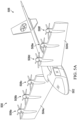
- FIGs. 1A and 1B illustrate an example tiltrotor aircraft 100, not in accordance with the appended claims, that is convertible between a VTOL or hover (also commonly referred to as helicopter) mode (shown in FIG. 1A ), which allows for vertical takeoff and landing, hovering, and low speed directional movement, and a cruise (also commonly referred to as airplane) mode (shown in FIG. 1B ), which allows for forward flight as well as horizontal takeoff and landing.
- Aircraft 100 includes a fuselage 102, wing 104, and a tail assembly 106.
- the aircraft further includes propulsion systems 112a, 112b, proximate outboard ends of wing 104.
- Wing tips 114a, 114b are fixedly connected to outboard sides of propulsion systems 112a, 112b, as will be described below.
- Each propulsion system 112a, 112b includes a drive system housing comprising a pylon 130a, 130b, and a rotatable open rotor assembly 132a, 132b, comprising a plurality of rotor blades 134a, 134b, connected to a rotor mast and configured to rotate about a rotor axis 136a, 136b.
- each rotor assembly 132a, 132b includes three (3) rotor blades; however, it should be recognized that more or fewer blades may be implemented.
- Each pylon 130a, 130b may house one or more electric motors therein configured to produce rotational energy that drives the rotation of rotor assembly 132a, 132b.
- each pylon 130a, 130b may house a gearbox therein that drives the rotation of rotor assembly 132a, 132b, wherein the gearbox receives rotational energy from a driveshaft.
- wing tips 114a, 114b are fixedly attached to outboard sides of pylons 130a, 130b. Inboard sides of pylons 130a, 130b, are tiltably connected to outboard ends of wing 104.
- propulsion systems 112a, 112b are each convertible, relative to fuselage 102, between a vertical position, as shown in FIG. 1A , and a horizontal position, as shown in FIG. 1B .
- Propulsion systems 112a, 112b are in the vertical position during vertical takeoff and landing mode. Vertical takeoff and landing mode may be considered to include hover operations of aircraft 100.
- Propulsion systems 112a, 112b are in the horizontal position during forward flight mode, in which aircraft 100 is in forward flight.
- propulsion systems 112a, 112b In forward flight mode, propulsion systems 112a, 112b, direct their respective thrusts in the aft direction to propel aircraft 100 forward.
- Aircraft 100 is operable to fly in all directions during the vertical takeoff and landing mode configuration of FIG. 1A , although faster forward flight is achievable while in the forward flight mode configuration of FIG. 1B .
- Propulsion systems 112a, 112b, including wing tips 114a, 114b may be tiltable between the vertical and horizontal positions by actuators (not shown) that are tiltable in response to commands originating from a pilot and/or a flight control system.
- linear actuators may be used, which attach to the wing tip via a spindle in the outboard tip ribs and attach to a clevis on the pylon support which forms the structure of the pylon.
- the dual or triply-redundant electric or hydraulic actuator extends pushing the pylon up greater than 90 degrees.
- a gimbal on the lower wing attach spindle allows the angle of the actuator to rotate as the pylon moves from horizontal to vertical.
- a rotary actuator could be used. The actuator would be installed at a radius about the pylon spindle such that movement of the rotary actuator about the radius would drive the pylon rotation.
- Each of the propulsion systems 112a, 112b may utilize a drive system comprising one or more electric motors and gearbox unit disposed within a respective pylon 130a, 130b as a power source to rotate the respective rotor assembly 132a, 132b about rotor axis 136a, 136b via a rotor mast.
- a drive system comprising one or more electric motors and gearbox unit disposed within a respective pylon 130a, 130b as a power source to rotate the respective rotor assembly 132a, 132b about rotor axis 136a, 136b via a rotor mast.
- FIGs. 2A and 2B illustrate an example tiltrotor aircraft 200, not in accordance with the appended claims, that is convertible between a VTOL or hover (also commonly referred to as helicopter) mode (shown in FIG. 2A ), which allows for vertical takeoff and landing, hovering, and low speed directional movement, and a cruise (also commonly referred to as airplane) mode (shown in FIG. 2B ), which allows for forward flight as well as horizontal takeoff and landing.
- Aircraft 200 includes a fuselage 202, wing 204 comprising wing segments 202a, 202b, tiltably connected to fuselage 202, and a tail assembly 206.
- the aircraft further includes propulsion systems 212a, 212b, integrated into respective wing segments 204a, 204b.
- Wing tips 214a, 214b are fixedly connected to outboard sides of propulsion systems 212a, 212b.
- each of propulsion systems 212a, 212b may include a drive system housing comprising a pylon, and a rotatable open rotor assembly comprising a plurality of rotor blades connected to a rotor mast and configured to rotate about a rotor axis.
- the rotor assembly of each of propulsion systems 212a, 212b includes three (3) rotor blades; however, it should be recognized that more or fewer blades may be implemented.
- Rotation of rotor assemblies of propulsion systems 212a, 212b generates lift while the aircraft 200 is operating in helicopter mode and thrust while the aircraft 200 is operating in airplane mode.
- propulsion systems 212a, 212b (including wing tips 214a, 214b), and wing segments 204a, 204b, which tilt relative to fuselage 202 between a first position ( FIG. 2A ), in which wing segments 204a, 204b, and propulsion systems 212a, 212b, are configured in a hover mode, and a second position ( FIG. 2B ), in which wing segments 204a, 204b, and propulsion systems 212a, 212b, are configured in a cruise mode.
- propulsion systems 212a, 212b are each convertible, relative to fuselage 202, between a vertical position, as shown in FIG. 2A , and a horizontal position, as shown in FIG. 2B .
- Propulsion systems 212a, 212b are in the vertical position during vertical takeoff and landing mode. Vertical takeoff and landing mode may be considered to include hover operations of aircraft 200.
- Propulsion systems 212a, 212b are in the horizontal position during forward flight mode, in which aircraft 200 is in forward flight. In forward flight mode, propulsion systems 212a, 212b, direct their respective thrusts in the aft direction to propel aircraft 200 forward. Aircraft 200 is operable to fly in all directions during the vertical takeoff and landing mode configuration of FIG. 2A , although faster forward flight is achievable while in the forward flight mode configuration of FIG. 2B .
- Propulsion systems 212a, 212b may be tiltable between the vertical and horizontal positions by actuators that are tiltable in response to commands originating from a pilot and/or a flight control system.
- a linear actuator (or a group of two or more linear actuators for redundancy) attached to the aft spar as shown in FIGs. 7A and 7B or a spindle connecting the two wing boxes as shown in FIGs. 6A and 6B and pushing the trailing edge of the wing down are possible implementations.
- FIGs. 3A and 3B illustrate an example tiltrotor aircraft 300, not in accordance with the appended claims, that is convertible between a VTOL or hover (also commonly referred to as helicopter) mode (shown in FIG. 3A ), which allows for vertical takeoff and landing, hovering, and low speed directional movement, and a cruise (also commonly referred to as airplane) mode (shown in FIG. 3B ), which allows for forward flight as well as horizontal takeoff and landing.
- Aircraft 300 includes a fuselage 302, wing 304, and tail assembly 306.
- the aircraft further includes propulsion systems 312a, 312b.
- Propulsion systems 312a, 312b are integrated into wing 304 proximate outboard ends thereof.
- Wing tips 314a, 314b are fixedly connected to outboard sides of propulsion systems 312a, 312b.
- each of propulsion systems 312a, 312b may include a drive system housing comprising a pylon, and a rotatable open rotor assembly comprising a plurality of rotor blades connected to a rotor mast and configured to rotate about a rotor axis.
- the rotor assembly of each of propulsion systems 312a, 312b includes three (3) rotor blades; however, it should be recognized that more or fewer blades may be implemented.
- Rotation of rotor assemblies of propulsion systems 312a, 312b generates lift while the aircraft 300 is operating in helicopter mode and thrust while the aircraft 300 is operating in airplane mode.
- wing 304 including propulsion systems 312a, 312b, and wing tips 314a, 314b, is tiltably connected to the fuselage 302, and tilts relative to the fuselage between a first position ( FIG. 3A ), in which wing 304 and propulsion systems 312a, 312b, are configured in a hover mode, and a second position ( FIG. 3B ), in which wing 304 and propulsion systems 312a, 312b, are configured in a cruise mode.
- wing 304 and propulsion systems 312a, 312b, can be selectively controlled in order to selectively control direction, thrust, and lift of aircraft 300.
- wing 304, including propulsion assemblies 312a, 312b is convertible, relative to fuselage 302, between a vertical position, as shown in FIG. 3A , and a horizontal position, as shown in FIG. 3B .
- Wing 304 and propulsion systems 312a, 312b are in the vertical position during vertical takeoff and landing mode. Vertical takeoff and landing mode may be considered to include hover operations of aircraft 300.
- Wing 304 and propulsion systems 312a, 312b are in the horizontal position during forward flight mode, in which aircraft 300 is in forward flight.
- propulsion systems 312a, 312b direct their respective thrusts in the aft direction to propel aircraft 300 forward.
- Aircraft 300 is operable to fly in all directions during the vertical takeoff and landing mode configuration of FIG. 3A , although faster forward flight is achievable while in the forward flight mode configuration of FIG. 3B .
- Wing 304 and propulsion systems 312a, 312b may be tiltable between the vertical and horizontal positions by actuators (not shown) that are tiltable in response to commands originating from a pilot and/or a flight control system.
- FIGs. 7A and 7B illustrate a possible actuator arrangement in which a linear actuator tilts the aft spar of the wing box down and forward up in a streamlined arrangement. Actuator attach points can be varied to tailor mechanical advantage.
- FIGs. 4A and 4B illustrate an example tiltrotor aircraft 400 that is convertible between a VTOL or hover (also commonly referred to as helicopter) mode (shown in FIG. 4A ), which allows for vertical takeoff and landing, hovering, and low speed directional movement, and a cruise (also commonly referred to as airplane) mode (shown in FIG. 4B ), which allows for forward flight as well as horizontal takeoff and landing.
- Aircraft 400 includes a fuselage 402, wings 404a, 404b, booms 406a, 406b, connected to opposite sides of the fuselage 402, and a tail assembly 407.
- aircraft further includes three pairs of propulsion systems, including a forward pair of boom-mounted propulsion systems 408a, 408b, an aft pair of boom-mounted propulsion systems 410a, 410b, and a pair of propulsion systems 412a, 412b.
- propulsion systems 412a, 412b are integrated into wings 404a, 404b, which are tiltably connected to outboard sides of booms 406a, 406b.
- Wing tips 414a, 414b are fixedly connected to outboard sides of propulsion systems 412a, 412b.
- Propulsion systems 408a, 408b are tiltably connected to the forward ends of wing booms 404a, 404b.
- Propulsion systems 410a, 410b are mounted to top surfaces of booms 406a, 406b, proximate the aft end of the fuselage 402.
- each of propulsion systems 408a, 408b, 410a, 410b, 412a, and 412b may include a drive system housing comprising a pylon, and a rotatable open rotor assembly comprising a plurality of rotor blades connected to a rotor mast and configured to rotate about a rotor axis.
- the rotor assembly of each of propulsion systems 408a, 408b, 412a, 412b includes five (5) rotor blades; however, it should be recognized that more or fewer blades may be implemented without departing from the scope of the embodiments described.
- rotor assemblies of propulsion systems 408a, 408b may include a different number of rotor blades than rotor assemblies of propulsion systems 412a, 412b. Rotation of rotor assemblies of propulsion systems 408a, 408b, 412a, and 412b generates lift while the aircraft 400 is operating in helicopter mode and thrust while the aircraft 400 is operating in airplane mode.
- each boom-mounted propulsion system 410a, 410b includes a drive system housing comprising a pylon and a rotatable open rotor assembly comprising a plurality of rotor blades connected to a rotor mast and configured to rotate about a rotor axis.
- each rotor assembly of propulsion systems 410a, 410b includes two (2) rotor blades; however, it should be recognized that more or fewer blades may be implemented without departing from the scope of the embodiments described. Rotation of rotor assemblies of propulsion systems 410a, 410b, generates lift while the aircraft 400 is operating in helicopter mode.
- rotor assemblies of propulsion systems 410a, 410b are illustrated as being disposed above (i.e., on top of) booms 406a, 406b, they may alternatively be disposed below (i.e., on the underside of) booms.
- propulsion systems 412a, 412b are integrated into wings 404a, 404b.
- Forward propulsion systems 408a, 408b are tiltably connected to forward ends of booms and tiltable between a first position ( FIG. 4A ), in which propulsion systems 408a, 408b, are configured in a hover mode, and a second position ( FIG. 4B ), in which propulsion systems 408a, 408b, are configured in a cruise mode.
- aft propulsion systems 410a, 410b are fixedly attached to booms 406a, 406b, aft of the wing 404 in hover mode and do not convert between hover mode ( FIG. 4A ) and cruise mode ( FIG. 4B ).
- propulsion systems 408a, 408b, 412a, 412b are each convertible, relative to fuselage 402, between a vertical position, as shown in FIG. 4A , and a horizontal position, as shown in FIG. 4B .
- Propulsion systems 408a, 408b, 412a, 412b are in the vertical position during vertical takeoff and landing mode.
- Vertical takeoff and landing mode may be considered to include hover operations of aircraft 400.
- Propulsion systems 408a, 408b, 412a, 412b are in the horizontal position during forward flight mode, in which aircraft 400 is in forward flight.
- propulsion systems 408a, 408b, 412a, 412b direct their respective thrusts in the aft direction to propel aircraft 400 forward.
- Aircraft 400 is operable to fly in all directions during the vertical takeoff and landing mode configuration of FIG. 4A , although faster forward flight is achievable while in the forward flight mode configuration of FIG. 4B .
- Wings 404a, 404b including propulsion systems 412a, 412b, and propulsion systems 408a, 408b, may be tiltable between the vertical and horizontal positions by actuators (not shown) that are tiltable in response to commands originating from a pilot and/or a flight control system.
- Linear actuators which attach to the wing via a spindle in the wing common to the wing ribs attach to a clevis on the side of the boom.
- the dual or triply- redundant electric or hydraulic actuator extends rotating the wing.
- propulsion systems 408a, 408b are shown and described as being tiltable between cruise and hover positions, those propulsion systems may be fixed in the hover positions, similarly to propulsion systems 410a, 410b.
- FIGs. 5A and 5B illustrate an example tiltrotor aircraft 500, not in accordance with the appended claims, that is convertible between a VTOL or hover (also commonly referred to as helicopter) mode (shown in FIG. 5A ), which allows for vertical takeoff and landing, hovering, and low speed directional movement, and a cruise (also commonly referred to as airplane) mode (shown in FIG. 5B ), which allows for forward flight as well as horizontal takeoff and landing.
- Aircraft 500 includes a fuselage 502, wings 504a, 504b, and a tail assembly 506.
- aircraft further includes a plurality of propulsion systems 508a-508f integrated into wings 504a, 504b.
- each of propulsion systems 508a-508f may include a drive system housing comprising a pylon, and a rotatable open rotor assembly comprising a plurality of rotor blades connected to a rotor mast and configured to rotate about a rotor axis.
- the rotor assembly of each of propulsion systems 508a-508f includes five (5) rotor blades; however, it should be recognized that more or fewer blades may be implemented without departing from the scope of the embodiments described. It should also be recognized that rotor assemblies of propulsion systems 508a-508f may include different numbers of rotor blades.
- propulsion systems 508a-508f lift while the aircraft 500 is operating in helicopter mode and thrust while the aircraft 500 is operating in airplane mode.
- wings 504a, 504b including propulsion systems 508a-508f, are tiltably connected to the fuselage 502, and tilt relative to the fuselage between a first position (FIG.53 A), in which wings 504a, 504b, and propulsion systems 508a-508f, are configured in a hover mode, and a second position ( FIG. 5B ), in which wings 504a, 504b, and propulsion systems 508a-508f are configured in a cruise mode.
- wings 504a, 504b, and rotor assemblies of propulsion systems 508a-508f can be selectively controlled in order to selectively control direction, thrust, and lift of aircraft 500.
- wings 504a, 504b, including propulsion systems 508a-508f are convertible, relative to fuselage 502, between a vertical position, as shown in FIG. 5A , and a horizontal position, as shown in FIG. 5B .
- Wings 504a, 504b, including propulsion systems 508a-508f are in the vertical position during vertical takeoff and landing mode. Vertical takeoff and landing mode may be considered to include hover operations of aircraft 500.
- Wings 504a, 504b, including propulsion systems 508a-508f are in the horizontal position during forward flight mode, in which aircraft 500 is in forward flight. In forward flight mode, propulsion systems 508a-508f, direct their respective thrusts in the aft direction to propel aircraft 500 forward. Aircraft 500 is operable to fly in all directions during the vertical takeoff and landing mode configuration of FIG. 5A , although faster forward flight is achievable while in the forward flight mode configuration of FIG. 5B . Wings 504a, 504b, and propulsion systems 508a-508f, may be tiltable between the vertical and horizontal positions by actuators (not shown) in response to commands originating from a pilot and/or a flight control system. Each wing or the complete wing may be actuated with a linear or rotary actuary. Examples of a possible mechanism are shown in Figures 6 and 7 . In this case several motor driving several rotors/props are arranged along the rotating wing.
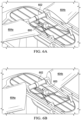
- FIGs. 6A and 6B illustrate in greater detail a mechanism for actuating a wing of a spindle wing configuration, such as illustrated in FIGs. 2A and 2B .
- FIGs. 6A and 6B show a linear actuator 600 actuating a spindle 602 connecting the left and right wing boxes 604a, 604b.
- Two or more linear actuators could also be used for redundancy.
- FIG. 6A shows the wings/wing boxes 604a, 604b, in horizontal mode.
- FIG. 6B shows the wings/wing boxes 604a, 604b in vertical mode.
- actuator 600 is a linear actuator, in various implementations, one or more rotary or other type of actuator may advantageously be employed.
- FIGs. 7A and 7B illustrate in greater detail a mechanism for actuating a wing of a carry-through wing configuration, such as illustrated in FIGs. 3A and 3B .
- a linear actuator 700 actuates a carry through torque box 702 of a continuous wing including left and right wing boxes 704a, 704b.
- Two or more linear actuators could also be used for redundancy.
- FIG. 7A shows the wings/wing boxes 704a, 704b, in horizontal mode.
- FIG. 7B shows the wings/wing boxes 704a, 704b in vertical mode.
- actuator 700 is a linear actuator, in various implementations, one or more rotary or other type of actuator may advantageously be employed.
- FIGs. 8A and 8B illustrate an example tiltrotor aircraft 800 that is convertible between a VTOL or hover (also commonly referred to as helicopter) mode (shown in FIG. 8A ), which allows for vertical takeoff and landing, hovering, and low speed directional movement, and a cruise (also commonly referred to as airplane) mode (shown in FIG. 8B ), which allows for forward flight as well as horizontal takeoff and landing.
- Aircraft 800 includes a fuselage 802, wing 804, and booms 806a, 806b, connected to the wing on opposite sides of the fuselage 802.
- the aircraft further includes three pairs of propulsion systems, including a first pair of boom-mounted propulsion systems 808a, 808b, a second pair of boom-mounted propulsion systems 810a, 810b, and a pair of wing-mounted propulsion systems 812a, 812b.
- propulsion systems 812a, 812b are tiltably connected to the leading edge of wing 804 at outboard ends thereof, while propulsion systems 808a, 808b, are tiltably connected to the forward end of booms 806a, 806b inboard of propulsion systems 812a, 812b.
- propulsion systems 808a, 808b may be tiltably connected to the forward edge of wing 804 inboard of propulsion systems 812a, 812b.
- Propulsion systems 810a, 810b are mounted to bottom surfaces of booms 806a, 806b, proximate the aft end or aft of the fuselage 802.
- Aircraft 800 further includes a tail assembly 813 at an aft end thereof.
- each of propulsion systems 808a, 808b, 810a, 810b, 812a, and 812b may include a drive system housing comprising a pylon, and a rotatable open rotor assembly comprising a plurality of rotor blades connected to a rotor mast and configured to rotate about a rotor axis.
- the rotor assembly of each of propulsion systems 808a, 808b, 812a, 812b includes five (5) rotor blades; however, it should be recognized that more or fewer blades may be implemented without departing from the scope of the embodiments described.
- rotor assemblies of propulsion systems 808a, 808b may include a different number of rotor blades than rotor assemblies of propulsion systems 812a, 812b. Rotation of rotor assemblies of propulsion systems 808a, 808b, 812a, and 812b generates lift while the aircraft 800 is operating in helicopter mode and thrust while the aircraft 800 is operating in airplane mode.
- each boom-mounted propulsion system 810a, 810b includes a drive system housing comprising a pylon and a rotatable open rotor assembly comprising a plurality of rotor blades connected to a rotor mast and configured to rotate about a rotor axis.
- each rotor assembly of propulsion systems 810a, 810b includes two (2) rotor blades; however, it should be recognized that more or fewer blades may be implemented without departing from the scope of the embodiments described.
- Rotation of rotor assemblies of propulsion systems 810a, 810b generates lift while the aircraft 800 is operating in helicopter mode.
- rotor assemblies of propulsion systems 810a, 810b are illustrated as being disposed below (i.e., on the underside of) booms 806a, 806b, they may alternatively be disposed above (i.e., on top of) booms.
- propulsion systems 808a, 808b, 812a, 812b are tiltably connected to the wing 804 and tilt relative to wing between a first position ( FIG. 8A ), in which propulsion systems 808a, 808b, 812a, 812b, are configured in a hover mode, and a second position ( FIG. 8B ), in which propulsion systems 808a, 808b, 812a, 812b, are configured in a cruise mode.
- aft propulsion systems 810a, 810b are fixedly attached to booms 806a, 806b, aft of the wing 804 in hover mode and do not convert between hover mode ( FIG. 8A ) and cruise mode ( FIG. 8B ).
- propulsion systems 808a, 808b, 812a, 812b can be selectively controlled in order to selectively control direction, thrust, and lift of aircraft 800.
- propulsion systems 808a, 808b, 812a, 812b are each convertible, relative to fuselage 802, between a vertical position, as shown in FIG. 8A , and a horizontal position, as shown in FIG. 8B .
- Propulsion systems 808a, 808b, 812a, 812b are in the vertical position during vertical takeoff and landing mode.
- Vertical takeoff and landing mode may be considered to include hover operations of aircraft 800.
- Propulsion systems 808a, 808b, 812a, 812b are in the horizontal position during forward flight mode, in which aircraft 800 is in forward flight. In forward flight mode, propulsion systems 808a, 808b, 812a, 812b, direct their respective thrusts in the aft direction to propel aircraft 800 forward.
- Aircraft 800 is operable to fly in all directions during the vertical takeoff and landing mode configuration of FIG. 8A , although faster forward flight is achievable while in the forward flight mode configuration of FIG. 8B .
- Propulsion systems 808a, 808b, 812a, 812b may be tiltable between the vertical and horizontal positions by actuators (not shown) that are tiltable in response to commands originating from a pilot and/or a flight control system.
- propulsion systems 808a, 808b are shown and described as being tiltable between cruise and hover positions, those propulsion systems may be fixed in the hover positions, similarly to propulsion systems 810a, 810b.
- rotor assemblies of propulsion systems 810a, 810b may cease rotation.
- propulsion systems 808a, 808b are also fixed (i.e., do not convert between hover and cruise modes)
- rotor assemblies thereof may also cease rotation when aircraft 800 is in cruise mode.
- stopping the rotor when in transition to cruise flight on the wing reduces power requirements not contributing to forward flight.
- Drag is reduced by stopping the rotor such that only the tip presents frontal area.
- Propulsive efficiency of the remaining rotors is increased as the remaining rotors blade loading increases in cruise in comparison to power lost as a function of rotating the blade.
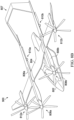
- FIG. 8C illustrates in greater detail connection of one of forward propulsion systems of aircraft 800 (e.g., propulsion system 808a) to forward end of one of booms of aircraft 800 (e.g., boom 806a).
- pylon 806a includes two clevises 840a, 840b, that engage opposite sides of a pylon support spindle 842 in a manner that enables on a bearing surface between horizontal and vertical (as shown in FIG. 8C .
- FIG. 9 illustrates a pylon configuration in which a rotor pylon 900 and rotation axis 902 are elevated above the wing torque box 904.
- a pylon support spindle 906 is engaged on opposite sides thereof by bearing surface of clevises 908a, 908b.
- a linear actuator (not shown in FIG. 9 ) attached to a spindle (not shown in FIG. 9 ) in the wing torque box 904 and to the pylon support 906 actuates the pylon 900 between horizontal (as shown in FIG. 9 ) and vertical orientations.
- FIG. 10 illustrates a drive system 1000 that may be deployed in any of the propulsion systems described hereinabove.
- drive system 1000 includes multiple electric motors 1002 for providing rotational energy to a rotor assembly 1004 via a gearbox 1006.
- FIG. 11 illustrates a drive system 1100 that may be deployed in any of the propulsion systems described hereinabove.
- drive system 1100 includes a single electrical motor for providing rotational energy to a rotor assembly 1102.
- the drive system (such as drive system 1000 or 1100) for a rotor assembly may tilt with the rotor assembly (e.g., located in a rotating pylon or in a rotating portion of a pylon) or may be fixed (i.e., non-tilting).
- the drive system may be located in a fixed portion of a partially tilting pylon, in which case a gearbox is used to allow transmittal across the rotation, or in the fuselage with a driveshaft down the wing.
- Various tilting rotor pylon embodiments include embodiments in which the entire pylon and outboard of the pylon rotates, the entire pylon (and outboard) and a portion of the inboard wing structure rotates, the entire pylon and the entire wing structure rotates (i.e., tiltwing), and a portion of the pylon rotates either in line with the pylon or above the wing structure.
- the electric motor or motors may be located in the rotating pylon, in a rotating portion of the pylon or a fixed portion of the pylon with a gearbox to allow transmittal across the rotation, and/or in the fuselage with a drive shaft down the wing and appropriate gearboxes for driving the rotor assembly.
- one or more motors could be located in the pylon and one or more motors could also be located in the fuselage with a down-wing drive shaft to allow redundancy with a reduced number of motors.
- Embodiments described herein support both flapping rotor and rigid rotor/prop pylon rotation.
- the pylon rotates about an axis within the wing or above the wing.
- none of the wing structure, a portion of the wing structure, or all of the wing structure may rotate with the pylon.
- One or more motors for driving a combining gearbox to drive rotors may be arrayed in the rotor pylon or in the fuselage with or without an interconnect between rotors. Linear or rotary actuators may be used to implement pylon rotation.
- Tilting portions offer a tradeoff between stalled wing in transition and a download in hover.
- Rotating the wing or a portion of the wing with the pylon increases the area of the wing seeing a high angle of attack and encountering stall versus additional download of a non-rotated wing in hover.
- a wing extension beyond the pylon increase cruise performance.
- rotor assemblies described herein may comprise any materials suitable for use with an aircraft rotor.
- rotor blades and other components may comprise carbon fiber, fiberglass, or aluminum; and rotor masts and other components may comprise steel or titanium.
- FIGURES illustrate the architecture, functionality, and/or operation of possible implementations of various embodiments of the present disclosure.
- Those of ordinary skill in the art would appreciate that the present disclosure may be readily used as a basis for designing or modifying other embodiments for carrying out the same purposes and/or achieving the same advantages of the embodiments introduced herein.
Landscapes
- Engineering & Computer Science (AREA)
- Aviation & Aerospace Engineering (AREA)
- Mechanical Engineering (AREA)
- Chemical & Material Sciences (AREA)
- Combustion & Propulsion (AREA)
- Automation & Control Theory (AREA)
- Transmission Devices (AREA)
- Toys (AREA)
Description
- This disclosure relates in general to the field of tiltrotor aircraft and, more particularly, though not exclusively, to various configurations for such aircraft.
- An electric vertical takeoff and landing (eVTOL) is a type of aircraft that uses electric power to supply rotational energy in an aircraft propulsion system for enabling the aircraft to hover, take off, and land vertically. Because of their versatility and lack of a need for a runway, eVTOLs are particularly useful for providing urban air mobility. As used herein, the term eVTOL also includes VTOLs that use hybrid electric propulsion systems. One particular type of eVTOL is an electric tiltrotor aircraft.
-
US2020/0391862A1 describes a tiltrotor aircraft having a vertical takeoff and landing (VTOL) flight mode and a forward flight mode, the aircraft comprising tiltable rotors located at forward boom ends, tiltable ducted fans located at wings aft of the forward boom ends, and aft rotors located on aft boom portions. -
WO2020/105045A1 describes air vehicle having an airframe, aerodynamic lift generating wings, and a propulsion system. The propulsion system provides propulsion to the air vehicle in powered aerodynamic flight mode and in vectored flight mode, and stability and control in vectored flight mode. -
EP3466812A1 describes a tiltrotor aircraft having a vertical takeoff and landing flight mode and a forward flight mode. The tiltrotor aircraft includes a longitudinally extending fuselage with a wing extending laterally therefrom having oppositely disposed wing tips distal from the fuselage. Tip booms respectively extend longitudinally from the wing tips. Forward rotors are coupled to the forward ends of the tip booms. -
US2012/0091257A1 describes a system and method for providing propulsion and control to an air vehicle, and for operating the vehicle, including at least three propulsion units that provide vertical thrust for vectored thrust flight, in which at least one or two of the propulsion units also provide thrust for vectored thrust cruising or aerodynamic flight by suitably tilting the respective propulsion units for changing the thrust vector thereof. - According to a first aspect of the invention, there is provided an aircraft according to claim 1.
- Optional and/or preferable features are set out in the dependent claims.
- To provide a more complete understanding of the present disclosure and features and advantages thereof, reference is made to the following description, taken in conjunction with the accompanying figures, in which like reference numerals represent like elements:
-
FIGs. 1A and1B illustrate an electric tiltrotor aircraft configuration; -
FIGs. 2A and2B illustrate an electric tiltrotor aircraft configuration; -
FIGs. 3A and 3B illustrate an electric tiltrotor aircraft configuration; -
FIGs. 4A and4B illustrate an electric tiltrotor aircraft configuration; -
FIGs. 5A and5B illustrate an electric tiltrotor aircraft configuration -
FIGs. 6A and 6B illustrate additional details of a spindle type of tiltrotor wing connection mechanism; -
FIGs. 7A and 7B illustrate additional details of a carry-through type of tiltrotor wing connection mechanism; -
FIGs. 8A and8B illustrate an electric tiltrotor aircraft configuration; -
FIG. 8C illustrates additional details of a tilting propulsion assembly connection mechanism; -
FIG. 9 illustrates additional details of pylon configuration where the rotor pylon and rotation point are elevated above the wing torque box; -
FIG. 10 illustrates a rotor assembly drive system; and -
FIG. 11 illustrates a rotor assembly drive system. - The following disclosure describes various illustrative embodiments and examples for implementing the features and functionality of the present disclosure. While particular components, arrangements, and/or features are described below in connection with various example embodiments, these are merely examples used to simplify the present disclosure and are not intended to be limiting. It will of course be appreciated that in the development of any actual embodiment, numerous implementation-specific decisions must be made to achieve the developer's specific goals, including compliance with system, business, and/or legal constraints, which may vary from one implementation to another. Moreover, it will be appreciated that, while such a development effort might be complex and time-consuming; it would nevertheless be a routine undertaking for those of ordinary skill in the art having the benefit of this disclosure.
- In the Specification, reference may be made to the spatial relationships between various components and to the spatial orientation of various aspects of components as depicted in the attached drawings. However, as will be recognized by those skilled in the art after a complete reading of the present disclosure, the devices, components, members, apparatuses, etc. described herein may be positioned in any desired orientation. Thus, the use of terms such as "above", "below", "upper", "lower", "top", "bottom", or other similar terms to describe a spatial relationship between various components or to describe the spatial orientation of aspects of such components, should be understood to describe a relative relationship between the components or a spatial orientation of aspects of such components, respectively, as the components described herein may be oriented in any desired direction. When used to describe a range of dimensions or other characteristics (e.g., time, pressure, temperature, length, width, etc.) of an element, operations, and/or conditions, the phrase "between X and Y" represents a range that includes X and Y.
- Additionally, as referred to herein in this Specification, the terms "forward", "aft", "inboard", and "outboard" may be used to describe relative relationship(s) between components and/or spatial orientation of aspect(s) of a component or components. The term "forward" may refer to a spatial direction that is closer to a front of an aircraft relative to another component or component aspect(s). The term "aft" may refer to a spatial direction that is closer to a rear of an aircraft relative to another component or component aspect(s). The term "inboard" may refer to a location of a component that is within the fuselage of an aircraft and/or a spatial direction that is closer to or along a centerline of the aircraft (wherein the centerline runs between the front and the rear of the aircraft) or other point of reference relative to another component or component aspect. The term "outboard" may refer to a location of a component that is outside the fuselage of an aircraft and/or a spatial direction that farther from the centerline of the aircraft or other point of reference relative to another component or component aspect.
- Further, the present disclosure may repeat reference numerals and/or letters in the various examples. This repetition is for the purpose of simplicity and clarity and does not in itself dictate a relationship between the various embodiments and/or configurations discussed. Example embodiments that may be used to implement the features and functionality of this disclosure will now be described with more particular reference to the accompanying FIGURES.
- Electric tiltrotor aircraft configurations described herein are characterized by tilting of the rotors on a wing. In various embodiments, the tiltrotor aircraft configuration rotates the rotor pylon at the side pylon of body, wing station inboard on the wing, or incorporating tiltwing elements with wing rotation as a whole. The degree of wing rotation with the pylon and placement of the axis of rotation relative to the wing are unique elements of embodiments described herein. Rotating a greater portion of the wing with the pylon reduces download of the rotor on the wing but makes transition of the wing from hovering flight to airplane mode flight more difficult, as the rotated portion of the wing will be stalled through a lot of transition increasing rotor power required in transition beyond that required for hover. Variation of wing rotation includes rotating only the pylon and none of the wing which make transition benign but increase power required in a hover to the downwash on the horizontal wing surfaces, rotating an outboard wing extension with the pylon which is a good compromise of download reduction and benign transition, rotating an inboard section of the wing with the pylon which or rotating the whole wing with the pylon both of which increase transition power required from a conventional tiltrotor but reduce download in hover. Pylon rotation actuation is effected through linear or rotary actuators forward, aft, or under the pylon are described herein.
-
FIGs. 1A and1B illustrate anexample tiltrotor aircraft 100, not in accordance with the appended claims, that is convertible between a VTOL or hover (also commonly referred to as helicopter) mode (shown inFIG. 1A ), which allows for vertical takeoff and landing, hovering, and low speed directional movement, and a cruise (also commonly referred to as airplane) mode (shown inFIG. 1B ), which allows for forward flight as well as horizontal takeoff and landing.Aircraft 100 includes afuselage 102,wing 104, and atail assembly 106. The aircraft further includespropulsion systems wing 104.Wing tips propulsion systems - Each
propulsion system pylon open rotor assembly rotor blades rotor axis FIGs. 1A and1B , eachrotor assembly rotor blades rotor axis pylon rotor assembly pylon rotor assembly - As illustrated in
FIGs. 1A and1B ,wing tips pylons pylons wing 104. In operation,wing tips propulsion systems wing 104 between a first position (FIG. 1A ), in whichpropulsion systems wing tips FIG. 1B ), in whichpropulsion systems wing tips - The position of
rotor assemblies individual rotor blades aircraft 100. As previously noted,propulsion systems fuselage 102, between a vertical position, as shown inFIG. 1A , and a horizontal position, as shown inFIG. 1B .Propulsion systems aircraft 100.Propulsion systems aircraft 100 is in forward flight. In forward flight mode,propulsion systems aircraft 100 forward.Aircraft 100 is operable to fly in all directions during the vertical takeoff and landing mode configuration ofFIG. 1A , although faster forward flight is achievable while in the forward flight mode configuration ofFIG. 1B .Propulsion systems wing tips propulsion systems respective pylon respective rotor assembly rotor axis -
FIGs. 2A and2B illustrate anexample tiltrotor aircraft 200, not in accordance with the appended claims, that is convertible between a VTOL or hover (also commonly referred to as helicopter) mode (shown inFIG. 2A ), which allows for vertical takeoff and landing, hovering, and low speed directional movement, and a cruise (also commonly referred to as airplane) mode (shown inFIG. 2B ), which allows for forward flight as well as horizontal takeoff and landing.Aircraft 200 includes afuselage 202, wing 204 comprising wing segments 202a, 202b, tiltably connected tofuselage 202, and atail assembly 206. The aircraft further includespropulsion systems respective wing segments Wing tips propulsion systems - Similar to the propulsion systems of
aircraft 100, each ofpropulsion systems FIGs. 2A and2B , the rotor assembly of each ofpropulsion systems propulsion systems aircraft 200 is operating in helicopter mode and thrust while theaircraft 200 is operating in airplane mode. - As illustrated in
FIGs. 2A and2B ,propulsion systems wing tips wing segments fuselage 202 between a first position (FIG. 2A ), in whichwing segments propulsion systems FIG. 2B ), in whichwing segments propulsion systems - The position of
wing segments propulsion systems propulsion systems aircraft 200. As previously noted,propulsion systems fuselage 202, between a vertical position, as shown inFIG. 2A , and a horizontal position, as shown inFIG. 2B .Propulsion systems aircraft 200.Propulsion systems aircraft 200 is in forward flight. In forward flight mode,propulsion systems aircraft 200 forward.Aircraft 200 is operable to fly in all directions during the vertical takeoff and landing mode configuration ofFIG. 2A , although faster forward flight is achievable while in the forward flight mode configuration ofFIG. 2B .Propulsion systems FIGs. 7A and 7B or a spindle connecting the two wing boxes as shown inFIGs. 6A and 6B and pushing the trailing edge of the wing down are possible implementations. -
FIGs. 3A and 3B illustrate anexample tiltrotor aircraft 300, not in accordance with the appended claims, that is convertible between a VTOL or hover (also commonly referred to as helicopter) mode (shown inFIG. 3A ), which allows for vertical takeoff and landing, hovering, and low speed directional movement, and a cruise (also commonly referred to as airplane) mode (shown inFIG. 3B ), which allows for forward flight as well as horizontal takeoff and landing.Aircraft 300 includes afuselage 302,wing 304, andtail assembly 306. The aircraft further includespropulsion systems Propulsion systems wing 304 proximate outboard ends thereof.Wing tips propulsion systems - Similar to the propulsion systems of
aircraft 100, each ofpropulsion systems FIGs. 3A and 3B , the rotor assembly of each ofpropulsion systems propulsion systems aircraft 300 is operating in helicopter mode and thrust while theaircraft 300 is operating in airplane mode. - As illustrated in
FIGs. 3A and 3B ,wing 304, includingpropulsion systems wing tips fuselage 302, and tilts relative to the fuselage between a first position (FIG. 3A ), in whichwing 304 andpropulsion systems FIG. 3B ), in whichwing 304 andpropulsion systems - The position of
wing 304 andpropulsion systems wing tips propulsion systems aircraft 300. As previously noted,wing 304, includingpropulsion assemblies fuselage 302, between a vertical position, as shown inFIG. 3A , and a horizontal position, as shown inFIG. 3B .Wing 304 andpropulsion systems aircraft 300.Wing 304 andpropulsion systems aircraft 300 is in forward flight. In forward flight mode,propulsion systems aircraft 300 forward.Aircraft 300 is operable to fly in all directions during the vertical takeoff and landing mode configuration ofFIG. 3A , although faster forward flight is achievable while in the forward flight mode configuration ofFIG. 3B .Wing 304 andpropulsion systems FIGs. 7A and 7B illustrate a possible actuator arrangement in which a linear actuator tilts the aft spar of the wing box down and forward up in a streamlined arrangement. Actuator attach points can be varied to tailor mechanical advantage. -
FIGs. 4A and4B illustrate anexample tiltrotor aircraft 400 that is convertible between a VTOL or hover (also commonly referred to as helicopter) mode (shown inFIG. 4A ), which allows for vertical takeoff and landing, hovering, and low speed directional movement, and a cruise (also commonly referred to as airplane) mode (shown inFIG. 4B ), which allows for forward flight as well as horizontal takeoff and landing.Aircraft 400 includes afuselage 402,wings booms fuselage 402, and atail assembly 407. In accordance with features of embodiments described herein, aircraft further includes three pairs of propulsion systems, including a forward pair of boom-mountedpropulsion systems propulsion systems propulsion systems propulsion systems wings booms Wing tips propulsion systems Propulsion systems wing booms Propulsion systems booms fuselage 402. - Similar to the propulsion systems of
aircraft 100, each ofpropulsion systems FIGs. 4A and4B , the rotor assembly of each ofpropulsion systems propulsion systems propulsion systems propulsion systems aircraft 400 is operating in helicopter mode and thrust while theaircraft 400 is operating in airplane mode. - In the illustrated embodiment, each boom-mounted
propulsion system FIGs. 4A and4B , each rotor assembly ofpropulsion systems propulsion systems aircraft 400 is operating in helicopter mode. It will be recognized that while rotor assemblies ofpropulsion systems booms - In accordance with features of embodiments described herein, and as illustrated in
FIGs. 4A and4B ,propulsion systems wings Wings propulsion systems wing extensions booms fuselage 402 between a first position (FIG. 4A ), in whichwings propulsion systems FIG. 4B ), in whichwings propulsion systems -
Forward propulsion systems FIG. 4A ), in whichpropulsion systems FIG. 4B ), in whichpropulsion systems aft propulsion systems booms FIG. 4A ) and cruise mode (FIG. 4B ). - The position of
wings propulsion systems propulsion systems propulsion systems aircraft 400. As previously noted,propulsion systems fuselage 402, between a vertical position, as shown inFIG. 4A , and a horizontal position, as shown inFIG. 4B .Propulsion systems aircraft 400.Propulsion systems aircraft 400 is in forward flight. In forward flight mode,propulsion systems aircraft 400 forward.Aircraft 400 is operable to fly in all directions during the vertical takeoff and landing mode configuration ofFIG. 4A , although faster forward flight is achievable while in the forward flight mode configuration ofFIG. 4B .Wings propulsion systems propulsion systems - It should be noted that, although
propulsion systems propulsion systems -
FIGs. 5A and5B illustrate anexample tiltrotor aircraft 500, not in accordance with the appended claims, that is convertible between a VTOL or hover (also commonly referred to as helicopter) mode (shown inFIG. 5A ), which allows for vertical takeoff and landing, hovering, and low speed directional movement, and a cruise (also commonly referred to as airplane) mode (shown inFIG. 5B ), which allows for forward flight as well as horizontal takeoff and landing.Aircraft 500 includes afuselage 502,wings tail assembly 506. In accordance with features of embodiments described herein, aircraft further includes a plurality ofpropulsion systems 508a-508f integrated intowings - Similar to the propulsion systems of
aircraft 100, each ofpropulsion systems 508a-508f may include a drive system housing comprising a pylon, and a rotatable open rotor assembly comprising a plurality of rotor blades connected to a rotor mast and configured to rotate about a rotor axis. As shown inFIGs. 5A and5B , the rotor assembly of each ofpropulsion systems 508a-508f includes five (5) rotor blades; however, it should be recognized that more or fewer blades may be implemented without departing from the scope of the embodiments described. It should also be recognized that rotor assemblies ofpropulsion systems 508a-508f may include different numbers of rotor blades. Still further, although six propulsion systems are illustrated, it will be recognized that more or fewer propulsion assemblies may be integrated intowings propulsion systems 508a-508f lift while theaircraft 500 is operating in helicopter mode and thrust while theaircraft 500 is operating in airplane mode. - As illustrated in
FIGs. 5A and5B ,wings propulsion systems 508a-508f, are tiltably connected to thefuselage 502, and tilt relative to the fuselage between a first position (FIG.53 A), in whichwings propulsion systems 508a-508f, are configured in a hover mode, and a second position (FIG. 5B ), in whichwings propulsion systems 508a-508f are configured in a cruise mode. - The position of
wings propulsion systems 508a-508f, as the pitch of individual rotor blades of all of the propulsion systems, can be selectively controlled in order to selectively control direction, thrust, and lift ofaircraft 500. As previously noted,wings propulsion systems 508a-508f, are convertible, relative tofuselage 502, between a vertical position, as shown inFIG. 5A , and a horizontal position, as shown inFIG. 5B .Wings propulsion systems 508a-508f, are in the vertical position during vertical takeoff and landing mode. Vertical takeoff and landing mode may be considered to include hover operations ofaircraft 500.Wings propulsion systems 508a-508f, are in the horizontal position during forward flight mode, in whichaircraft 500 is in forward flight. In forward flight mode,propulsion systems 508a-508f, direct their respective thrusts in the aft direction to propelaircraft 500 forward.Aircraft 500 is operable to fly in all directions during the vertical takeoff and landing mode configuration ofFIG. 5A , although faster forward flight is achievable while in the forward flight mode configuration ofFIG. 5B .Wings propulsion systems 508a-508f, may be tiltable between the vertical and horizontal positions by actuators (not shown) in response to commands originating from a pilot and/or a flight control system. Each wing or the complete wing may be actuated with a linear or rotary actuary. Examples of a possible mechanism are shown inFigures 6 and7 . In this case several motor driving several rotors/props are arranged along the rotating wing. -
FIGs. 6A and 6B illustrate in greater detail a mechanism for actuating a wing of a spindle wing configuration, such as illustrated inFIGs. 2A and2B . In particular,FIGs. 6A and 6B show alinear actuator 600 actuating aspindle 602 connecting the left andright wing boxes FIG. 6A shows the wings/wing boxes FIG. 6B shows the wings/wing boxes FIGs. 6A and 6B ,actuator 600 is a linear actuator, in various implementations, one or more rotary or other type of actuator may advantageously be employed. -
FIGs. 7A and 7B illustrate in greater detail a mechanism for actuating a wing of a carry-through wing configuration, such as illustrated inFIGs. 3A and 3B . InFIGs. 7A and 7B , alinear actuator 700 actuates a carry throughtorque box 702 of a continuous wing including left andright wing boxes FIG. 7A shows the wings/wing boxes FIG. 7B shows the wings/wing boxes FIGs. 7A and 7B ,actuator 700 is a linear actuator, in various implementations, one or more rotary or other type of actuator may advantageously be employed. -
FIGs. 8A and8B illustrate anexample tiltrotor aircraft 800 that is convertible between a VTOL or hover (also commonly referred to as helicopter) mode (shown inFIG. 8A ), which allows for vertical takeoff and landing, hovering, and low speed directional movement, and a cruise (also commonly referred to as airplane) mode (shown inFIG. 8B ), which allows for forward flight as well as horizontal takeoff and landing.Aircraft 800 includes afuselage 802,wing 804, andbooms fuselage 802. The aircraft further includes three pairs of propulsion systems, including a first pair of boom-mountedpropulsion systems propulsion systems propulsion systems propulsion systems wing 804 at outboard ends thereof, whilepropulsion systems booms propulsion systems propulsion systems wing 804 inboard ofpropulsion systems Propulsion systems booms fuselage 802.Aircraft 800 further includes a tail assembly 813 at an aft end thereof. - Similar to the propulsion systems of
aircraft 100, each ofpropulsion systems FIGs. 8A and8B , the rotor assembly of each ofpropulsion systems propulsion systems propulsion systems propulsion systems aircraft 800 is operating in helicopter mode and thrust while theaircraft 800 is operating in airplane mode. - In the illustrated embodiment, each boom-mounted
propulsion system FIGs. 8A and8B , each rotor assembly ofpropulsion systems propulsion systems aircraft 800 is operating in helicopter mode. It will be recognized that while rotor assemblies ofpropulsion systems booms - In accordance with features of embodiments described herein, and as illustrated in
FIGs. 8A and8B ,propulsion systems wing 804 and tilt relative to wing between a first position (FIG. 8A ), in whichpropulsion systems FIG. 8B ), in whichpropulsion systems aft propulsion systems booms wing 804 in hover mode and do not convert between hover mode (FIG. 8A ) and cruise mode (FIG. 8B ). - The position of rotor assemblies of
propulsion systems propulsion systems aircraft 800. As previously noted,propulsion systems fuselage 802, between a vertical position, as shown inFIG. 8A , and a horizontal position, as shown inFIG. 8B .Propulsion systems aircraft 800.Propulsion systems aircraft 800 is in forward flight. In forward flight mode,propulsion systems aircraft 800 forward.Aircraft 800 is operable to fly in all directions during the vertical takeoff and landing mode configuration ofFIG. 8A , although faster forward flight is achievable while in the forward flight mode configuration ofFIG. 8B .Propulsion systems - It should be noted that, although
propulsion systems propulsion systems - In accordance with features of embodiments described herein, in certain embodiments, when
aircraft 800 is in cruise mode, rotor assemblies ofpropulsion systems propulsion systems aircraft 800 is in cruise mode. For rotors fixed in a hover or horizontal position, stopping the rotor when in transition to cruise flight on the wing reduces power requirements not contributing to forward flight. Drag is reduced by stopping the rotor such that only the tip presents frontal area. Propulsive efficiency of the remaining rotors is increased as the remaining rotors blade loading increases in cruise in comparison to power lost as a function of rotating the blade. -
FIG. 8C illustrates in greater detail connection of one of forward propulsion systems of aircraft 800 (e.g.,propulsion system 808a) to forward end of one of booms of aircraft 800 (e.g.,boom 806a). InFIG. 8 ,pylon 806a includes twoclevises pylon support spindle 842 in a manner that enables on a bearing surface between horizontal and vertical (as shown inFIG. 8C . -
FIG. 9 illustrates a pylon configuration in which arotor pylon 900 androtation axis 902 are elevated above thewing torque box 904. Apylon support spindle 906 is engaged on opposite sides thereof by bearing surface of clevises 908a, 908b. A linear actuator (not shown inFIG. 9 ) attached to a spindle (not shown inFIG. 9 ) in thewing torque box 904 and to thepylon support 906 actuates thepylon 900 between horizontal (as shown inFIG. 9 ) and vertical orientations. -
FIG. 10 illustrates adrive system 1000 that may be deployed in any of the propulsion systems described hereinabove. As shown inFIG. 10 drive system 1000 includes multipleelectric motors 1002 for providing rotational energy to arotor assembly 1004 via agearbox 1006. -
FIG. 11 illustrates adrive system 1100 that may be deployed in any of the propulsion systems described hereinabove. As shown inFIG. 11 ,drive system 1100 includes a single electrical motor for providing rotational energy to arotor assembly 1102. - The drive system (such as
drive system 1000 or 1100) for a rotor assembly may tilt with the rotor assembly (e.g., located in a rotating pylon or in a rotating portion of a pylon) or may be fixed (i.e., non-tilting). In embodiments in which the drive system is fixed, the drive system may be located in a fixed portion of a partially tilting pylon, in which case a gearbox is used to allow transmittal across the rotation, or in the fuselage with a driveshaft down the wing. There may be a drive assembly in the pylon and a drive shaft and a group of motors disposed within the fuselage to allow redundancy with a reduced number of motors. - The electric tiltrotor configurations described herein are characterized by tilting of the rotors on a wing. The tiltrotor configurations described herein rotate the rotor pylon at the side pylon of body, at a wing station inboard on the wing, or by incorporating tiltwing elements with wing rotation as a whole. The degree of wing rotation with the pylon and placement of the axis of rotation relative to the wing may be customized depending on the embodiment. Additionally, the number of motors and the manner in which the motors are arranged in a rotating or fixed pylon or inboard in the fuselage with a drive shaft extending through the wing to the rotor assembly may also be customized depending on the embodiment. Pylon rotation may be actuated using one or more linear and/or rotary actuators located forward of, behind, or beneath the pylon depending on the embodiment.
- Various tilting rotor pylon embodiments include embodiments in which the entire pylon and outboard of the pylon rotates, the entire pylon (and outboard) and a portion of the inboard wing structure rotates, the entire pylon and the entire wing structure rotates (i.e., tiltwing), and a portion of the pylon rotates either in line with the pylon or above the wing structure. Additionally, the electric motor or motors may be located in the rotating pylon, in a rotating portion of the pylon or a fixed portion of the pylon with a gearbox to allow transmittal across the rotation, and/or in the fuselage with a drive shaft down the wing and appropriate gearboxes for driving the rotor assembly. Additionally, one or more motors could be located in the pylon and one or more motors could also be located in the fuselage with a down-wing drive shaft to allow redundancy with a reduced number of motors.
- Embodiments described herein support both flapping rotor and rigid rotor/prop pylon rotation. The pylon rotates about an axis within the wing or above the wing. In various embodiments, none of the wing structure, a portion of the wing structure, or all of the wing structure may rotate with the pylon. One or more motors for driving a combining gearbox to drive rotors may be arrayed in the rotor pylon or in the fuselage with or without an interconnect between rotors. Linear or rotary actuators may be used to implement pylon rotation.
- Tilting portions offer a tradeoff between stalled wing in transition and a download in hover. Rotating the wing or a portion of the wing with the pylon increases the area of the wing seeing a high angle of attack and encountering stall versus additional download of a non-rotated wing in hover. A wing extension beyond the pylon increase cruise performance.
- It should be appreciated that aircraft illustrated herein, such as
aircraft 100, is merely illustrative of a variety of aircraft that can implement the embodiments disclosed herein. The components of rotor assemblies described herein may comprise any materials suitable for use with an aircraft rotor. For example, rotor blades and other components may comprise carbon fiber, fiberglass, or aluminum; and rotor masts and other components may comprise steel or titanium. - The diagrams in the FIGURES illustrate the architecture, functionality, and/or operation of possible implementations of various embodiments of the present disclosure. Those of ordinary skill in the art would appreciate that the present disclosure may be readily used as a basis for designing or modifying other embodiments for carrying out the same purposes and/or achieving the same advantages of the embodiments introduced herein.
Claims (13)
- An aircraft (400, 800) comprising:a fuselage (402, 802) ;a wing (404a, 404b, 804) connected to the fuselage (402, 802)first and second propulsion systems (408a, 408b, 412a, 412b, 808a, 808b, 812a, 812b) connected to the wing on opposite sides of the fuselage (402, 802), wherein at least a portion of each of the first and second propulsion systems (408a, 408b, 412a, 412b, 808a, 808b, 812a, 812b) are tiltable between a first position in which the aircraft (400, 800) is in a hover mode and a second position in which the aircraft is in a cruise mode;a pair of booms (406a, 406b, 806a, 806b) that are connected to opposite sides of the fuselage (402, 802); andan aft pair of boom-mounted propulsion systems (410a, 410b, 810a, 810b), wherein the aft pair of boom-mounted propulsion systems (410a, 410b, 810a, 810b) are fixedly attached to the pair of booms (406a, 406b, 806a, 806b);wherein the wing (404a, 404b, 804) comprises wing tips (414a, 414b) disposed outboard of the first and second propulsion systems (408a, 408b, 412a, 412b, 808a, 808b, 812a, 812b); andwherein each of the first and second propulsion systems (408a, 408b, 412a, 412b, 808a, 808b, 812a, 812b) is an open rotor assembly including a pylon and a rotor assembly comprising a plurality of rotor blades.
- The aircraft (400, 800) of claim 1, wherein the aircraft is a hybrid electric vertical takeoff and landing craft or an electric vertical takeoff and landing aircraft (VTOL).
- The aircraft (400, 800) of claim 1 or 2, wherein the aft pair of boom mounted propulsion systems are configured to cease rotation when the aircraft is in a cruise mode.
- The aircraft (400, 800) of claim 3, wherein the aft pair of boom mounted propulsion systems each comprise a rotor assembly with two blades, and in the cruise mode the aircraft is configured to stop the rotor assembly of the aft pair of boom mounted propulsion systems (410a, 410b, 810a, 810b) with only a tip of the blades presenting a frontal area.
- The aircraft (400) of any preceding claim, wherein the aft pair of boom-mounted propulsion systems (410a, 410b) is mounted on the top of the pair of booms (406a, 406b).
- The aircraft (400, 800) of any preceding claim, comprising a forward pair of boom-mounted propulsion systems (408a, 408b, 808a, 808b).
- The aircraft (400, 800) of claim 6, wherein each of the forward pair of boom-mounted propulsion systems (408a, 408b, 808a, 808b) is mounted on the forward ends of the pair of booms (406a, 406b, 806a, 806b).
- The aircraft (400, 800) of any preceding claim, comprising a tail assembly (407, 807) connected to each of the pair of booms (406a, 406b, 806a, 806b).
- The aircraft (400) of claim 8 when dependent on claim 7, wherein a tilt angle of the aft pair of boom-mounted propulsion systems (410a, 410b) causes a component of the thrust from each of the aft pair of boom-mounted propulsion systems (410a, 410b) to provide a yaw moment.
- The aircraft (400, 800) of any preceding claim, wherein each of the first and second propulsion systems comprises an electric motor, and the electric motor of each of the first and second propulsions systems is located in a rotating portion of the pylon.
- The aircraft (400, 800) of any preceding claim, wherein the first and second propulsion systems are wing-mounted propulsion systems (412a, 412b, 812a, 812b).
- The aircraft (400, 800) of any preceding claim, wherein at least a portion of the wing (404a, 404b, 804) is tiltable between a first position in which the aircraft is in a hover mode and a second position in which the aircraft is in a cruise mode.
- The aircraft (400, 800) of claim 12, wherein the tiltable portion of the wing (404a, 404b, 804) comprises the wing tips (414a, 414b) disposed outboard of the first and second propulsion systems.
Applications Claiming Priority (2)
| Application Number | Priority Date | Filing Date | Title |
|---|---|---|---|
| US17/324,184 US11718397B2 (en) | 2021-05-19 | 2021-05-19 | Electric tiltrotor aircraft |
| EP21178367.5A EP4091940B1 (en) | 2021-05-19 | 2021-06-08 | Electric tiltrotor aircraft |
Related Parent Applications (2)
| Application Number | Title | Priority Date | Filing Date |
|---|---|---|---|
| EP21178367.5A Division EP4091940B1 (en) | 2021-05-19 | 2021-06-08 | Electric tiltrotor aircraft |
| EP21178367.5A Division-Into EP4091940B1 (en) | 2021-05-19 | 2021-06-08 | Electric tiltrotor aircraft |
Publications (2)
| Publication Number | Publication Date |
|---|---|
| EP4230523A1 EP4230523A1 (en) | 2023-08-23 |
| EP4230523B1 true EP4230523B1 (en) | 2024-10-23 |
Family
ID=76355307
Family Applications (2)
| Application Number | Title | Priority Date | Filing Date |
|---|---|---|---|
| EP23171219.1A Active EP4230523B1 (en) | 2021-05-19 | 2021-06-08 | Tiltrotor aircraft |
| EP21178367.5A Active EP4091940B1 (en) | 2021-05-19 | 2021-06-08 | Electric tiltrotor aircraft |
Family Applications After (1)
| Application Number | Title | Priority Date | Filing Date |
|---|---|---|---|
| EP21178367.5A Active EP4091940B1 (en) | 2021-05-19 | 2021-06-08 | Electric tiltrotor aircraft |
Country Status (2)
| Country | Link |
|---|---|
| US (3) | US11718397B2 (en) |
| EP (2) | EP4230523B1 (en) |
Families Citing this family (9)
| Publication number | Priority date | Publication date | Assignee | Title |
|---|---|---|---|---|
| USD978719S1 (en) * | 2020-10-20 | 2023-02-21 | Guangdong Syma Model Aircraft Industrial Co., Ltd. | Aircraft toy |
| CN112550668B (en) * | 2021-03-01 | 2021-06-15 | 北京清航紫荆装备科技有限公司 | Cross double-rotor helicopter and horizontal tail control system |
| US12420922B2 (en) | 2021-07-31 | 2025-09-23 | Supernal, Llc | Vertical take-off and landing craft systems and methods |
| US11787551B1 (en) * | 2022-10-06 | 2023-10-17 | Archer Aviation, Inc. | Vertical takeoff and landing aircraft electric engine configuration |
| US12240589B2 (en) * | 2022-12-12 | 2025-03-04 | Textron Innovations Inc. | Linear actuator system |
| US20240308656A1 (en) * | 2023-03-14 | 2024-09-19 | Orbital Composites, Inc. | Navigable aeronautical and nautical craft |
| CN117341966A (en) * | 2023-11-02 | 2024-01-05 | 刘品良 | Vertically taking-off and landing aircraft with partially fixed wing type wing-generator co-rotation |
| GB2638939A (en) * | 2023-11-20 | 2025-09-10 | Sora Aviation Ltd | Large vertical takeoff and landing aircraft |
| USD1079585S1 (en) * | 2025-03-20 | 2025-06-17 | Zihang Zhong | Aircraft |
Family Cites Families (31)
| Publication number | Priority date | Publication date | Assignee | Title |
|---|---|---|---|---|
| US3666209A (en) | 1970-02-24 | 1972-05-30 | Boeing Co | V/stol aircraft with variable tilt wing |
| WO2009126905A1 (en) * | 2008-04-11 | 2009-10-15 | Karem Aircraft, Inc. | Tilt actuation for a rotorcraft |
| US8469306B2 (en) | 2009-01-27 | 2013-06-25 | Ira F. Kuhn, Jr. | Purebred and hybrid electric VTOL tilt rotor aircraft |
| IL199009A (en) * | 2009-05-27 | 2013-11-28 | Israel Aerospace Ind Ltd | Air vehicle |
| WO2011146349A2 (en) * | 2010-05-17 | 2011-11-24 | Piasecki Aircraft Corp. | Modular and morphable air vehicle |
| DE102010021022A1 (en) | 2010-05-19 | 2011-11-24 | Eads Deutschland Gmbh | Flipper aircraft |
| JP2014528382A (en) * | 2011-10-17 | 2014-10-27 | ユー ティアン | Aircraft combining fixed wing and electric multi-rotor |
| US9475579B2 (en) | 2013-08-13 | 2016-10-25 | The United States Of America As Represented By The Administrator Of The National Aeronautics And Space Administration | Vertical take-off and landing vehicle with increased cruise efficiency |
| US20190291863A1 (en) | 2016-05-18 | 2019-09-26 | A^3 By Airbus Llc | Vertical takeoff and landing aircraft with tilted-wing configurations |
| US10011349B2 (en) * | 2016-08-31 | 2018-07-03 | Bell Helicopter Textron Inc. | Tiltrotor aircraft having rotatable wing extensions |
| US9981734B2 (en) * | 2016-09-19 | 2018-05-29 | Bell Helicopter Textron Inc. | Cross-wing driveshaft channel |
| US10279901B2 (en) | 2016-09-21 | 2019-05-07 | Bell Helicopter Textron Inc. | Rotating proprotor arrangement for a tiltrotor aircraft |
| EP3548377B1 (en) | 2016-11-29 | 2021-08-04 | Pfammatter, Thomas | Electrical vertical take-off and landing aircraft |
| CN110506003B (en) * | 2017-05-08 | 2024-01-05 | 英西图公司 | Modular aircraft with vertical takeoff and landing capability and method of operating the same |
| US10513334B2 (en) | 2017-06-12 | 2019-12-24 | Textron Innovations Inc. | X-tiltwing aircraft |
| US10676188B2 (en) * | 2017-10-04 | 2020-06-09 | Textron Innovations Inc. | Tiltrotor aircraft having a downwardly tiltable aft rotor |
| IL263301B2 (en) * | 2018-11-25 | 2023-09-01 | Israel Aerospace Ind Ltd | Air vehicle and method of operation of air vehicle |
| US11433998B2 (en) * | 2019-02-20 | 2022-09-06 | Shanghai Autoflight Co., Ltd. | Fixed wing UAV |
| US11091258B2 (en) * | 2019-06-14 | 2021-08-17 | Bell Textron Inc. | VTOL aircraft with tilting rotors and tilting ducted fans |
| EP3838753B1 (en) | 2019-12-17 | 2022-03-16 | LEONARDO S.p.A. | Convertiplane |
| US11480072B2 (en) | 2019-12-31 | 2022-10-25 | Textron Innovations Inc. | Stator and duct ring structural fittings |
| US11472533B2 (en) * | 2019-12-31 | 2022-10-18 | Textron Innovations Inc. | Stators located aft of duct ring |
| US11738862B2 (en) | 2020-01-28 | 2023-08-29 | Overair, Inc. | Fail-operational vtol aircraft |
| US11554865B2 (en) * | 2020-02-18 | 2023-01-17 | Aurora Flight Sciences Corporation | Vertical take-off and landing (VTOL) aircraft and related methods |
| US11554859B2 (en) | 2020-03-04 | 2023-01-17 | Textron Innovations Inc. | Electric drive system line replaceable unit with integrated thermal cooling |
| US11731779B2 (en) | 2020-06-01 | 2023-08-22 | Textron Innovations Inc. | Drivetrain for an aircraft including gearbox with coaxial input and output shafts |
| US11390395B2 (en) | 2020-06-25 | 2022-07-19 | Textron Innovations Inc. | Aircraft rotor assembly with segmented input shaft for electric motor stack and gearbox unit |
| US11420760B2 (en) | 2020-06-29 | 2022-08-23 | Textron Innovations Inc. | Sealed coaxial input and output shafts |
| US11661180B2 (en) * | 2020-07-08 | 2023-05-30 | Archer Aviation Inc. | Systems and methods for power distribution in electric aircraft |
| US12168508B2 (en) * | 2021-03-29 | 2024-12-17 | Textron Innovations Inc. | Tilting hexrotor aircraft |
| US12528579B2 (en) * | 2021-03-29 | 2026-01-20 | Textron Innovations Inc. | Tilting hexrotor aircraft |
-
2021
- 2021-05-19 US US17/324,184 patent/US11718397B2/en active Active
- 2021-06-08 EP EP23171219.1A patent/EP4230523B1/en active Active
- 2021-06-08 EP EP21178367.5A patent/EP4091940B1/en active Active
-
2023
- 2023-06-20 US US18/337,703 patent/US12240600B2/en active Active
-
2025
- 2025-01-29 US US19/040,768 patent/US12534197B2/en active Active
Also Published As
| Publication number | Publication date |
|---|---|
| US20220371727A1 (en) | 2022-11-24 |
| EP4230523A1 (en) | 2023-08-23 |
| EP4091940A1 (en) | 2022-11-23 |
| US20230348054A1 (en) | 2023-11-02 |
| US12240600B2 (en) | 2025-03-04 |
| US11718397B2 (en) | 2023-08-08 |
| EP4091940B1 (en) | 2023-09-06 |
| US20250171139A1 (en) | 2025-05-29 |
| US12534197B2 (en) | 2026-01-27 |
Similar Documents
| Publication | Publication Date | Title |
|---|---|---|
| EP4091940B1 (en) | Electric tiltrotor aircraft | |
| US20250263167A1 (en) | Tilting Hexrotor Aircraft | |
| EP3296202B1 (en) | Wing extension winglets for tiltrotor aircraft | |
| US8256704B2 (en) | Vertical/short take-off and landing aircraft | |
| KR20210008017A (en) | Electric tiltrotor aircraft | |
| EP2242684B1 (en) | Rotorcraft with variable incident wing | |
| US6398157B1 (en) | Aircraft | |
| US11603191B1 (en) | Stowable lift rotors for VTOL aircraft | |
| US12084173B2 (en) | Rotor alignment tab | |
| US12528579B2 (en) | Tilting hexrotor aircraft | |
| US9611037B1 (en) | Use of auxiliary rudders for yaw control at low speed | |
| US11691725B2 (en) | Twin fuselage tiltrotor aircraft | |
| EP4036002B1 (en) | Electric tiltrotor aircraft with fixed motors | |
| US20240278909A1 (en) | Rotor position control system | |
| US9139298B2 (en) | Rotorcraft control system for rotorcraft with two or more rotor systems | |
| US20200391859A1 (en) | Vtol aircraft with leading edge tilting ducted fans | |
| EP3838752B1 (en) | Convertiplane and associated folding method | |
| US11807357B2 (en) | Tilting hexrotor aircraft | |
| EP3805100B1 (en) | Vtol aircraft | |
| CN114802711A (en) | Unmanned aerial vehicle with single duct at tail part | |
| CN114987737A (en) | Tail active variable-pitch ducted propulsion unmanned aerial vehicle | |
| EP4011771B1 (en) | Pylon conversion actuator for tiltrotor aircraft | |
| CN113264181B (en) | Tailless composite helicopter | |
| KR101150855B1 (en) | Flight control structure of duct type flight robot |
Legal Events
| Date | Code | Title | Description |
|---|---|---|---|
| PUAI | Public reference made under article 153(3) epc to a published international application that has entered the european phase |
Free format text: ORIGINAL CODE: 0009012 |
|
| STAA | Information on the status of an ep patent application or granted ep patent |
Free format text: STATUS: REQUEST FOR EXAMINATION WAS MADE |
|
| STAA | Information on the status of an ep patent application or granted ep patent |
Free format text: STATUS: EXAMINATION IS IN PROGRESS |
|
| 17P | Request for examination filed |
Effective date: 20230503 |
|
| AC | Divisional application: reference to earlier application |
Ref document number: 4091940 Country of ref document: EP Kind code of ref document: P |
|
| AK | Designated contracting states |
Kind code of ref document: A1 Designated state(s): AL AT BE BG CH CY CZ DE DK EE ES FI FR GB GR HR HU IE IS IT LI LT LU LV MC MK MT NL NO PL PT RO RS SE SI SK SM TR |
|
| 17Q | First examination report despatched |
Effective date: 20230804 |
|
| GRAP | Despatch of communication of intention to grant a patent |
Free format text: ORIGINAL CODE: EPIDOSNIGR1 |
|
| STAA | Information on the status of an ep patent application or granted ep patent |
Free format text: STATUS: GRANT OF PATENT IS INTENDED |
|
| INTG | Intention to grant announced |
Effective date: 20240611 |
|
| GRAS | Grant fee paid |
Free format text: ORIGINAL CODE: EPIDOSNIGR3 |
|
| GRAA | (expected) grant |
Free format text: ORIGINAL CODE: 0009210 |
|
| STAA | Information on the status of an ep patent application or granted ep patent |
Free format text: STATUS: THE PATENT HAS BEEN GRANTED |
|
| AC | Divisional application: reference to earlier application |
Ref document number: 4091940 Country of ref document: EP Kind code of ref document: P |
|
| AK | Designated contracting states |
Kind code of ref document: B1 Designated state(s): AL AT BE BG CH CY CZ DE DK EE ES FI FR GB GR HR HU IE IS IT LI LT LU LV MC MK MT NL NO PL PT RO RS SE SI SK SM TR |
|
| REG | Reference to a national code |
Ref country code: GB Ref legal event code: FG4D |
|
| REG | Reference to a national code |
Ref country code: CH Ref legal event code: EP |
|
| REG | Reference to a national code |
Ref country code: DE Ref legal event code: R096 Ref document number: 602021020837 Country of ref document: DE |
|
| REG | Reference to a national code |
Ref country code: IE Ref legal event code: FG4D |
|
| REG | Reference to a national code |
Ref country code: LT Ref legal event code: MG9D |
|
| REG | Reference to a national code |
Ref country code: NL Ref legal event code: MP Effective date: 20241023 |
|
| REG | Reference to a national code |
Ref country code: AT Ref legal event code: MK05 Ref document number: 1734648 Country of ref document: AT Kind code of ref document: T Effective date: 20241023 |
|
| PG25 | Lapsed in a contracting state [announced via postgrant information from national office to epo] |
Ref country code: NL Free format text: LAPSE BECAUSE OF FAILURE TO SUBMIT A TRANSLATION OF THE DESCRIPTION OR TO PAY THE FEE WITHIN THE PRESCRIBED TIME-LIMIT Effective date: 20241023 |
|
| PG25 | Lapsed in a contracting state [announced via postgrant information from national office to epo] |
Ref country code: NL Free format text: LAPSE BECAUSE OF FAILURE TO SUBMIT A TRANSLATION OF THE DESCRIPTION OR TO PAY THE FEE WITHIN THE PRESCRIBED TIME-LIMIT Effective date: 20241023 |
|
| PG25 | Lapsed in a contracting state [announced via postgrant information from national office to epo] |
Ref country code: PT Free format text: LAPSE BECAUSE OF FAILURE TO SUBMIT A TRANSLATION OF THE DESCRIPTION OR TO PAY THE FEE WITHIN THE PRESCRIBED TIME-LIMIT Effective date: 20250224 Ref country code: IS Free format text: LAPSE BECAUSE OF FAILURE TO SUBMIT A TRANSLATION OF THE DESCRIPTION OR TO PAY THE FEE WITHIN THE PRESCRIBED TIME-LIMIT Effective date: 20250223 Ref country code: HR Free format text: LAPSE BECAUSE OF FAILURE TO SUBMIT A TRANSLATION OF THE DESCRIPTION OR TO PAY THE FEE WITHIN THE PRESCRIBED TIME-LIMIT Effective date: 20241023 |
|
| PG25 | Lapsed in a contracting state [announced via postgrant information from national office to epo] |
Ref country code: FI Free format text: LAPSE BECAUSE OF FAILURE TO SUBMIT A TRANSLATION OF THE DESCRIPTION OR TO PAY THE FEE WITHIN THE PRESCRIBED TIME-LIMIT Effective date: 20241023 |
|
| PG25 | Lapsed in a contracting state [announced via postgrant information from national office to epo] |
Ref country code: BG Free format text: LAPSE BECAUSE OF FAILURE TO SUBMIT A TRANSLATION OF THE DESCRIPTION OR TO PAY THE FEE WITHIN THE PRESCRIBED TIME-LIMIT Effective date: 20241023 |
|
| PG25 | Lapsed in a contracting state [announced via postgrant information from national office to epo] |
Ref country code: ES Free format text: LAPSE BECAUSE OF FAILURE TO SUBMIT A TRANSLATION OF THE DESCRIPTION OR TO PAY THE FEE WITHIN THE PRESCRIBED TIME-LIMIT Effective date: 20241023 |
|
| PG25 | Lapsed in a contracting state [announced via postgrant information from national office to epo] |
Ref country code: NO Free format text: LAPSE BECAUSE OF FAILURE TO SUBMIT A TRANSLATION OF THE DESCRIPTION OR TO PAY THE FEE WITHIN THE PRESCRIBED TIME-LIMIT Effective date: 20250123 |
|
| PG25 | Lapsed in a contracting state [announced via postgrant information from national office to epo] |
Ref country code: LV Free format text: LAPSE BECAUSE OF FAILURE TO SUBMIT A TRANSLATION OF THE DESCRIPTION OR TO PAY THE FEE WITHIN THE PRESCRIBED TIME-LIMIT Effective date: 20241023 Ref country code: AT Free format text: LAPSE BECAUSE OF FAILURE TO SUBMIT A TRANSLATION OF THE DESCRIPTION OR TO PAY THE FEE WITHIN THE PRESCRIBED TIME-LIMIT Effective date: 20241023 Ref country code: GR Free format text: LAPSE BECAUSE OF FAILURE TO SUBMIT A TRANSLATION OF THE DESCRIPTION OR TO PAY THE FEE WITHIN THE PRESCRIBED TIME-LIMIT Effective date: 20250124 |
|
| PG25 | Lapsed in a contracting state [announced via postgrant information from national office to epo] |
Ref country code: PL Free format text: LAPSE BECAUSE OF FAILURE TO SUBMIT A TRANSLATION OF THE DESCRIPTION OR TO PAY THE FEE WITHIN THE PRESCRIBED TIME-LIMIT Effective date: 20241023 |
|
| PG25 | Lapsed in a contracting state [announced via postgrant information from national office to epo] |
Ref country code: RS Free format text: LAPSE BECAUSE OF FAILURE TO SUBMIT A TRANSLATION OF THE DESCRIPTION OR TO PAY THE FEE WITHIN THE PRESCRIBED TIME-LIMIT Effective date: 20250123 |
|
| PG25 | Lapsed in a contracting state [announced via postgrant information from national office to epo] |
Ref country code: SM Free format text: LAPSE BECAUSE OF FAILURE TO SUBMIT A TRANSLATION OF THE DESCRIPTION OR TO PAY THE FEE WITHIN THE PRESCRIBED TIME-LIMIT Effective date: 20241023 |
|
| PGFP | Annual fee paid to national office [announced via postgrant information from national office to epo] |
Ref country code: DE Payment date: 20250627 Year of fee payment: 5 |
|
| PG25 | Lapsed in a contracting state [announced via postgrant information from national office to epo] |
Ref country code: DK Free format text: LAPSE BECAUSE OF FAILURE TO SUBMIT A TRANSLATION OF THE DESCRIPTION OR TO PAY THE FEE WITHIN THE PRESCRIBED TIME-LIMIT Effective date: 20241023 |
|
| PGFP | Annual fee paid to national office [announced via postgrant information from national office to epo] |
Ref country code: GB Payment date: 20250627 Year of fee payment: 5 |
|
| PG25 | Lapsed in a contracting state [announced via postgrant information from national office to epo] |
Ref country code: EE Free format text: LAPSE BECAUSE OF FAILURE TO SUBMIT A TRANSLATION OF THE DESCRIPTION OR TO PAY THE FEE WITHIN THE PRESCRIBED TIME-LIMIT Effective date: 20241023 |
|
| PGFP | Annual fee paid to national office [announced via postgrant information from national office to epo] |
Ref country code: FR Payment date: 20250625 Year of fee payment: 5 |
|
| PG25 | Lapsed in a contracting state [announced via postgrant information from national office to epo] |
Ref country code: RO Free format text: LAPSE BECAUSE OF FAILURE TO SUBMIT A TRANSLATION OF THE DESCRIPTION OR TO PAY THE FEE WITHIN THE PRESCRIBED TIME-LIMIT Effective date: 20241023 |
|
| REG | Reference to a national code |
Ref country code: DE Ref legal event code: R097 Ref document number: 602021020837 Country of ref document: DE |
|
| PG25 | Lapsed in a contracting state [announced via postgrant information from national office to epo] |
Ref country code: SK Free format text: LAPSE BECAUSE OF FAILURE TO SUBMIT A TRANSLATION OF THE DESCRIPTION OR TO PAY THE FEE WITHIN THE PRESCRIBED TIME-LIMIT Effective date: 20241023 |
|
| PG25 | Lapsed in a contracting state [announced via postgrant information from national office to epo] |
Ref country code: CZ Free format text: LAPSE BECAUSE OF FAILURE TO SUBMIT A TRANSLATION OF THE DESCRIPTION OR TO PAY THE FEE WITHIN THE PRESCRIBED TIME-LIMIT Effective date: 20241023 |
|
| PG25 | Lapsed in a contracting state [announced via postgrant information from national office to epo] |
Ref country code: IT Free format text: LAPSE BECAUSE OF FAILURE TO SUBMIT A TRANSLATION OF THE DESCRIPTION OR TO PAY THE FEE WITHIN THE PRESCRIBED TIME-LIMIT Effective date: 20241023 |
|
| PLBE | No opposition filed within time limit |
Free format text: ORIGINAL CODE: 0009261 |
|
| STAA | Information on the status of an ep patent application or granted ep patent |
Free format text: STATUS: NO OPPOSITION FILED WITHIN TIME LIMIT |
|
| PG25 | Lapsed in a contracting state [announced via postgrant information from national office to epo] |
Ref country code: SE Free format text: LAPSE BECAUSE OF FAILURE TO SUBMIT A TRANSLATION OF THE DESCRIPTION OR TO PAY THE FEE WITHIN THE PRESCRIBED TIME-LIMIT Effective date: 20241023 |
|
| 26N | No opposition filed |
Effective date: 20250724 |
|
| REG | Reference to a national code |
Ref country code: CH Ref legal event code: H13 Free format text: ST27 STATUS EVENT CODE: U-0-0-H10-H13 (AS PROVIDED BY THE NATIONAL OFFICE) Effective date: 20260127 |
|
| PG25 | Lapsed in a contracting state [announced via postgrant information from national office to epo] |
Ref country code: MC Free format text: LAPSE BECAUSE OF FAILURE TO SUBMIT A TRANSLATION OF THE DESCRIPTION OR TO PAY THE FEE WITHIN THE PRESCRIBED TIME-LIMIT Effective date: 20241023 |
|
| PG25 | Lapsed in a contracting state [announced via postgrant information from national office to epo] |
Ref country code: LU Free format text: LAPSE BECAUSE OF NON-PAYMENT OF DUE FEES Effective date: 20250608 |
|
| REG | Reference to a national code |
Ref country code: BE Ref legal event code: MM Effective date: 20250630 |
|
| PG25 | Lapsed in a contracting state [announced via postgrant information from national office to epo] |
Ref country code: IE Free format text: LAPSE BECAUSE OF NON-PAYMENT OF DUE FEES Effective date: 20250608 |
|
| PG25 | Lapsed in a contracting state [announced via postgrant information from national office to epo] |
Ref country code: BE Free format text: LAPSE BECAUSE OF NON-PAYMENT OF DUE FEES Effective date: 20250630 |
|
| PG25 | Lapsed in a contracting state [announced via postgrant information from national office to epo] |
Ref country code: CH Free format text: LAPSE BECAUSE OF NON-PAYMENT OF DUE FEES Effective date: 20250630 |