EP4230508A1 - Vehicle body lower structure of automobile - Google Patents
Vehicle body lower structure of automobile Download PDFInfo
- Publication number
- EP4230508A1 EP4230508A1 EP21900648.3A EP21900648A EP4230508A1 EP 4230508 A1 EP4230508 A1 EP 4230508A1 EP 21900648 A EP21900648 A EP 21900648A EP 4230508 A1 EP4230508 A1 EP 4230508A1
- Authority
- EP
- European Patent Office
- Prior art keywords
- frame part
- corrugated plate
- beam portion
- diagonal
- impact absorbing
- Prior art date
- Legal status (The legal status is an assumption and is not a legal conclusion. Google has not performed a legal analysis and makes no representation as to the accuracy of the status listed.)
- Pending
Links
Images



Classifications
-
- B—PERFORMING OPERATIONS; TRANSPORTING
- B62—LAND VEHICLES FOR TRAVELLING OTHERWISE THAN ON RAILS
- B62D—MOTOR VEHICLES; TRAILERS
- B62D21/00—Understructures, i.e. chassis frame on which a vehicle body may be mounted
- B62D21/15—Understructures, i.e. chassis frame on which a vehicle body may be mounted having impact absorbing means, e.g. a frame designed to permanently or temporarily change shape or dimension upon impact with another body
- B62D21/152—Front or rear frames
-
- B—PERFORMING OPERATIONS; TRANSPORTING
- B60—VEHICLES IN GENERAL
- B60R—VEHICLES, VEHICLE FITTINGS, OR VEHICLE PARTS, NOT OTHERWISE PROVIDED FOR
- B60R19/00—Wheel guards; Radiator guards, e.g. grilles; Obstruction removers; Fittings damping bouncing force in collisions
- B60R19/02—Bumpers, i.e. impact receiving or absorbing members for protecting vehicles or fending off blows from other vehicles or objects
- B60R19/18—Bumpers, i.e. impact receiving or absorbing members for protecting vehicles or fending off blows from other vehicles or objects characterised by the cross-section; Means within the bumper to absorb impact
-
- B—PERFORMING OPERATIONS; TRANSPORTING
- B62—LAND VEHICLES FOR TRAVELLING OTHERWISE THAN ON RAILS
- B62D—MOTOR VEHICLES; TRAILERS
- B62D21/00—Understructures, i.e. chassis frame on which a vehicle body may be mounted
- B62D21/15—Understructures, i.e. chassis frame on which a vehicle body may be mounted having impact absorbing means, e.g. a frame designed to permanently or temporarily change shape or dimension upon impact with another body
- B62D21/157—Understructures, i.e. chassis frame on which a vehicle body may be mounted having impact absorbing means, e.g. a frame designed to permanently or temporarily change shape or dimension upon impact with another body for side impacts
-
- B—PERFORMING OPERATIONS; TRANSPORTING
- B62—LAND VEHICLES FOR TRAVELLING OTHERWISE THAN ON RAILS
- B62D—MOTOR VEHICLES; TRAILERS
- B62D25/00—Superstructure or monocoque structure sub-units; Parts or details thereof not otherwise provided for
- B62D25/02—Side panels
- B62D25/025—Side sills thereof
-
- B—PERFORMING OPERATIONS; TRANSPORTING
- B62—LAND VEHICLES FOR TRAVELLING OTHERWISE THAN ON RAILS
- B62D—MOTOR VEHICLES; TRAILERS
- B62D25/00—Superstructure or monocoque structure sub-units; Parts or details thereof not otherwise provided for
- B62D25/20—Floors or bottom sub-units
-
- B—PERFORMING OPERATIONS; TRANSPORTING
- B60—VEHICLES IN GENERAL
- B60R—VEHICLES, VEHICLE FITTINGS, OR VEHICLE PARTS, NOT OTHERWISE PROVIDED FOR
- B60R19/00—Wheel guards; Radiator guards, e.g. grilles; Obstruction removers; Fittings damping bouncing force in collisions
- B60R19/02—Bumpers, i.e. impact receiving or absorbing members for protecting vehicles or fending off blows from other vehicles or objects
- B60R19/18—Bumpers, i.e. impact receiving or absorbing members for protecting vehicles or fending off blows from other vehicles or objects characterised by the cross-section; Means within the bumper to absorb impact
- B60R2019/1806—Structural beams therefor, e.g. shock-absorbing
-
- B—PERFORMING OPERATIONS; TRANSPORTING
- B60—VEHICLES IN GENERAL
- B60R—VEHICLES, VEHICLE FITTINGS, OR VEHICLE PARTS, NOT OTHERWISE PROVIDED FOR
- B60R19/00—Wheel guards; Radiator guards, e.g. grilles; Obstruction removers; Fittings damping bouncing force in collisions
- B60R19/02—Bumpers, i.e. impact receiving or absorbing members for protecting vehicles or fending off blows from other vehicles or objects
- B60R19/18—Bumpers, i.e. impact receiving or absorbing members for protecting vehicles or fending off blows from other vehicles or objects characterised by the cross-section; Means within the bumper to absorb impact
- B60R2019/1806—Structural beams therefor, e.g. shock-absorbing
- B60R2019/1813—Structural beams therefor, e.g. shock-absorbing made of metal
-
- B—PERFORMING OPERATIONS; TRANSPORTING
- B60—VEHICLES IN GENERAL
- B60R—VEHICLES, VEHICLE FITTINGS, OR VEHICLE PARTS, NOT OTHERWISE PROVIDED FOR
- B60R19/00—Wheel guards; Radiator guards, e.g. grilles; Obstruction removers; Fittings damping bouncing force in collisions
- B60R19/02—Bumpers, i.e. impact receiving or absorbing members for protecting vehicles or fending off blows from other vehicles or objects
- B60R19/18—Bumpers, i.e. impact receiving or absorbing members for protecting vehicles or fending off blows from other vehicles or objects characterised by the cross-section; Means within the bumper to absorb impact
- B60R2019/186—Additional energy absorbing means supported on bumber beams, e.g. cellular structures or material
- B60R2019/1866—Cellular structures
-
- B—PERFORMING OPERATIONS; TRANSPORTING
- B60—VEHICLES IN GENERAL
- B60Y—INDEXING SCHEME RELATING TO ASPECTS CROSS-CUTTING VEHICLE TECHNOLOGY
- B60Y2306/00—Other features of vehicle sub-units
- B60Y2306/01—Reducing damages in case of crash, e.g. by improving battery protection
-
- B—PERFORMING OPERATIONS; TRANSPORTING
- B62—LAND VEHICLES FOR TRAVELLING OTHERWISE THAN ON RAILS
- B62D—MOTOR VEHICLES; TRAILERS
- B62D25/00—Superstructure or monocoque structure sub-units; Parts or details thereof not otherwise provided for
- B62D25/04—Door pillars ; windshield pillars
Definitions
- the present invention relates to an automobile underbody structure.
- Patent Document 1 discloses a structure in which a zigzag-shaped connecting member is attached between a vehicle-body side portion and a chassis.
- Patent Document 2 discloses a bumper stay provided with an X-shaped reinforcing rib in the interior of a hollow portion having a front wall, a rear wall, and curved side walls.
- a pole side impact test to evaluate the energy absorption performance by making a vehicle collide with a pole serves as an evaluation method of the energy absorption performance.
- the pole side impact test it is specified in advance which portion of the vehicle is made to collide with the pole.
- the cross member is preferably disposed at a position brought into contact with the pole.
- the problem associated with such entry of the structural member into the vehicle-interior side as described above arises not only for the side collision between the cross members but also, for example, similarly, at the time of collision with a bumper beam between front member sides. Accordingly, without being limited to any collision direction, a deformation of the structural member into the vehicle-interior side at collision time can be preferably restrained.
- Patent Document 1 is a structure in which the zigzag-shaped connecting member transmits a collision load to the side sill, and is not a structure in which a deformation itself of the side sill is restrained.
- the bumper stay in Patent Document 2 functions as a crash box, and does not have a structure in which a deformation of structural members into the vehicle-interior side at collision time is restrained.
- the present invention has been made in consideration of the above circumstances, and has an object to reduce the entry amount of the structural member into the vehicle-interior side at collision time.
- an automobile underbody structure includes: a plurality of spaced first frame parts; a second frame part having a hollow portion extending so that an axial direction of the first frame part is a normal direction when seen from a vehicle height direction; and an impact absorbing member disposed in the hollow portion of the second frame part, wherein: the second frame part has a first wall portion and a second wall portion facing the first wall portion; the first wall portion is connected to vehicle-exterior end faces of the first frame parts in the axial direction; the impact absorbing member includes: a first beam portion extending along an axial direction of the second frame part; a second beam portion facing the first beam portion; and a corrugated plate portion connected to the first beam portion and the second beam portion between the first beam portion and the second beam portion, wherein: the first beam portion is connected to the first wall portion of the second frame part; the second beam portion is connected to the second wall portion of the second frame part; the corrugated plate portion includes: a first beam portion extending along an axial direction of the second frame part; the second
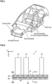
- FIG. 1 is a view illustrating one example of a body framework of an automobile.
- the body framework of the automobile includes, for example, a cross member (floor cross member) extending in a vehicle width direction, a side sill extending in a vehicle length direction, a bumper beam extending in the vehicle width direction, a side member extending in the vehicle length direction, and the like as illustrated in FIG. 1 .
- FIG. 2 is a view illustrating a schematic configuration of an underbody structure 1 according to the first embodiment.
- the underbody structure 1 of this embodiment includes a plurality of first frame parts 10 extending in an X direction and a second frame part 20 extending in a Y direction.
- FIG. 2 is a view of the underbody structure 1 being seen from a vehicle height direction (Z direction), and thus the "second frame part 20 extending in the Y direction" can also be reworded as the second frame part 20 extending so that an axial direction (extending direction) of the first frame part 10 is a normal direction when seen from the vehicle height direction.
- the respective first frame parts 10 are spaced along an axial direction of the second frame part 20 (Y direction). Further, the second frame part 20 is connected to vehicle-exterior end faces of the first frame parts 10.
- the first frame parts 10 and the second frame part 20 may be directly connected to one another, or may be indirectly connected by providing some member between the first frame parts 10 and the second frame part 20.
- the first frame part 10 is a structural member such as, for example, a cross member and a side member, and a member which exhibits energy absorption performance or impact resistance performance when a collision load is input from the axial direction.
- the second frame part 20 is the side sill.
- the side sill extends so that the axial direction of the cross member (X direction) is the normal direction, and is connected to the vehicle-exterior end faces of the cross members.
- the X direction in the present description and the drawings is the vehicle width direction
- the Y direction therein is the vehicle length direction.
- the second frame part 20 is the bumper beam.
- the bumper beam extends so that the axial direction of the side member (X direction) is the normal direction, and is connected to the vehicle-exterior end faces of the side members with crash boxes therebetween.
- the first frame parts 10 are the side members
- the second frame part 20 is the bumper beam
- the X direction in the present description and the drawings is the vehicle length direction
- the Y direction therein is the vehicle width direction.
- the side member may be a front side member or may be a rear side member.
- the bumper beam may be a front bumper beam or may be a rear bumper beam.
- the second frame part 20 is the front bumper beam
- the second frame part 20 is the rear bumper beam.
- a shape and a material of the first frame part 10 is not particularly limited as long as they are suitable as the structural member of the underbody structure 1 of automobiles.
- the first frame part 10 whose cross section perpendicular to the axial direction (X direction) is in a closed cross-sectional shape, is in a shape having a square tube-shaped hollow portion.
- a metallic material such as a steel sheet having, for example, a tensile strength of 590 MPa or more
- a metallic material such as an aluminum alloy member or a magnesium alloy member, or the like can be employed.
- a length of the first frame part 10 in the axial direction is, for example, 500 to 1500 mm, and a plate thickness of the first frame part 10 is, for example, 1 to 5 mm.
- a section size of the first frame part 10 is, for example, 30 to 200 mm square.
- FIG. 3 is a view illustrating a cross section taken along A-A in FIG. 2 , and indicates a cross section perpendicular to the axial direction of the second frame part 20 (Y direction).
- the second frame part 20 has a hollow portion 21 extending in the axial direction (Y direction).
- the hollow portion 21 of this embodiment is formed by joining two members such as an inner member 22 and an outer member 23 to each other as illustrated in FIG. 3 .
- the inner member 22 is a hat-shaped member including a top plate 22a, a vertical wall 22b, and a flange 22c
- the outer member 23 is a hat-shaped member including a top plate 23a, a vertical wall 23b, and a flange 23c.
- the hollow portion 21 of this embodiment is formed of the two hat-shaped members, and for example, either member of the two hat-shaped members may be a flat plate. Further, the hollow portion 21 need not be limited to one formed by connecting a plurality of members, but may be formed by, for example, extrusion molding. Further, a shape of the hollow portion 21 on a cut surface perpendicular to the axial direction of the second frame part 20 is not limited to a square tube shape.
- the metallic material such as the steel sheet having, for example, the tensile strength of 590 MPa or more, the metallic material such as the aluminum alloy member or the magnesium alloy member, or the like can be employed.
- a length of the second frame part 20 in the axial direction (Y direction) is, for example, 1000 to 3000 mm, and a plate thickness of the second frame part 20 is, for example, 1 to 5 mm.
- a section size of the second frame part 20 is, for example, 50 to 200 mm square.
- the second frame part 20 includes a first wall portion 20a and a second wall portion 20b.
- the first wall portion 20a and the second wall portion 20b face each other, and the first wall portion 20a is connected to the vehicle-exterior end faces of the first frame parts 10 in the axial direction (X direction).
- the first wall portion 20a corresponds to the top plate 22a of the inner member 22, and the second wall portion 20b corresponds to the top plate 23a of the outer member 23.
- the underbody structure 1 includes an impact absorbing member 30 in the hollow portion 21 of the second frame part 20 as illustrated in FIG. 2 to FIG. 5 .
- the impact absorbing member 30 includes a first beam portion 31, a second beam portion 32, and a corrugated plate portion 33.
- the first beam portion 31 and the second beam portion 32 face each other, and the first beam portion 31 and the second beam portion 32 each extend along the axial direction of the second frame part 20 (Y direction).
- a length of each of the first beam portion 31 and the second beam portion 32 in the extending direction (Y direction) is at least longer than a distance between the two adjacent first frame parts 10, and the first beam portion 31 and the second beam portion 32 each have a length extending across the two adjacent first frame parts 10.
- the first beam portion 31 of this embodiment is formed in a plate shape, and connected to the first wall portion 20a of the second frame part 20.
- the second beam portion 32 of this embodiment is formed in a plate shape, and connected to the second wall portion 20b of the second frame part 20.
- the corrugated plate portion 33 is connected to the first beam portion 31 and the second beam portion 32 so as to extend across between the first beam portion 31 and the second beam portion 32.
- the corrugated plate portion 33 of this embodiment continuously extends along the axial direction of the second frame part 20 (Y direction).
- the corrugated plate portion 33 has a first diagonal portion 34, a second diagonal portion 35, a first top portion 36, and a second top portion 37.
- the first diagonal portion 34 extends in a direction from the second beam portion 32 toward the first beam portion 31, and the second diagonal portion 35 extends in a direction from the first beam portion 31 toward the second beam portion 32.
- the first top portion 36 and the second top portion 37 are each a portion to which the first diagonal portion 34 and the second diagonal portion 35 are connected, and the first top portion 36 is a connection portion on the first beam portion 31 side, and the second top portion 37 is a connection portion on the second beam portion 32 side.
- the first top portion 36 and the second top portion 37 of this embodiment are each formed in a flat-plate shape, the first top portion 36 is connected to the first beam portion 31, and the second top portion 37 is connected to the second beam portion 32.
- each of the first top portion 36 and the second top portion 37 is present in plurality, and the first top portions 36 and the second top portions 37 are alternately positioned in the axial direction of the second frame part 20.
- all the first top portions 36 are preferably connected to the first beam portion 31, but as long as the position of the corrugated plate portion 33 with respect to the first beam portion 31 can be fixed, not all the first top portions 36 need to be connected to the first beam portion 31.
- some of the first top portions 36 are only required to be simply in contact with the first beam portion 31 or be in close proximity to the first beam portion 31 without being connected thereto.
- not all the second top portions 37 need to be connected to the second beam portion 32.
- an angle ⁇ made by the first diagonal portion 34 and the second diagonal portion 35 is set optionally, and from the viewpoint of effectively restraining the entry amount of the second frame part 20 into the vehicle-interior side as presented in later-described examples, the angle ⁇ when the corrugated plate portion 33 is provided in a region, in the second frame part 20, to which the first frame part 10 is connected is preferably 70 degrees or less. The angle is more preferably 60 degrees or less. Further, the angle ⁇ when the corrugated plate portion 33 is provided between the adjacent first frame parts 10 is preferably 40 to 80 degrees. The angle ⁇ in this case is preferably 50 degrees or more, and preferably 70 degrees or less.
- the metallic material such as the steel sheet having, for example, the tensile strength of 590 MPa or more, the metallic material such as the aluminum alloy member or the magnesium alloy member, or the like can be employed.
- a plate thickness of each of the first beam portion 31, the second beam portion 32, and the corrugated plate portion 33 is, for example, 1 to 10 mm.
- a connecting means of the first beam portion 31 of the impact absorbing member 30 and the first wall portion 20a of the second frame part 20, a connecting means of the second beam portion 32 of the impact absorbing member 30 and the second wall portion 20b of the second frame part 20, a connecting means of the corrugated plate portion 33 of the impact absorbing member 30 and the first beam portion 31, a connecting means of the corrugated plate portion 33 and the second beam portion 32, and the like are not particularly limited.
- a mechanical joining means such as riveting, or a joining means such as arc welding or spot welding can be employed.
- a shape of the first top portion 36 and the second top portion 37 is not limited to the flat-plate shape as in this embodiment, but appropriately changed depending on the employed connecting means.
- the first beam portion 31, the second beam portion 32, and the corrugated plate portion 33 are formed of respective separate members, but may be integrally molded by, for example, extrusion molding. Note that vehicle-height-direction lengths of the first beam portion 31, the second beam portion 32, and the corrugated plate portion 33 are each appropriately changed depending on required energy absorption performance or a weight limit.
- a connection position of the impact absorbing member 30 in the vehicle height direction (Z direction) with respect to the second frame part 20 is preferably positioned in a region, in the second frame part 20, in which the first frame parts 10 are connected.
- the impact absorbing member 30 is disposed in a middle portion in the vehicle height direction of the second frame part 20, and when the first frame part 10 is disposed in the vicinity of an upper end portion of the second frame part 20 as in FIG. 6 , the impact absorbing member 30 is preferably also disposed in the vicinity of the upper end portion of the second frame part 20.
- the underbody structure 1 of this embodiment is constituted as described above.
- the collision load when a collision load from the X direction is input to a region, of the second frame part 20, between the two adjacent first frame parts 10, the collision load can be easily distributed to a region other than a collision point by providing the impact absorbing member 30.
- the impact absorbing member 30 in the impact absorbing member 30, providing the second beam portion 32 extending in the Y direction causes the collision load input from the X direction to the second frame part 20 to also spread in the Y direction in the course of a deformation of the second beam portion 32 and to be also transmitted to the first diagonal portions 34 and the second diagonal portions 35 in the region other than the collision point. Further, disposing the first diagonal portions 34 and the second diagonal portions 35 to be inclined in a manner to form an angle with each other causes the collision load transmitted to the first diagonal portions 34 and the second diagonal portions 35 to further spread in the Y direction. Further, the collision load transmitted from the first diagonal portions 34 or the second diagonal portions 35 to the first beam portion 31 further spreads in the Y direction in the course of a deformation of the first beam portion 31 similarly to the second beam portion 32.
- such a distribution of the collision load as described above at collision time also uses material portions in the region other than the collision point, which enables withstanding of the collision load. As a result, the entry amount of the second frame part 20 into the vehicle-interior side at collision time can be reduced.
- FIG. 7 is a view illustrating a schematic configuration of an underbody structure 1 according to a second embodiment
- FIG. 8 is a perspective view of an impact absorbing member 30 of the second embodiment.
- a region in which a corrugated plate portion 33 is not provided in an extending direction of the impact absorbing member 30 (Y direction) is present.
- the impact absorbing member 30 includes a plurality of corrugated plate portions 33a, 33b, and the respective corrugated plate portions 33a, 33b are spaced along the extending direction of the impact absorbing member 30.
- the respective corrugated plate portions 33a, 33b are provided in regions R, in a second frame part 20, to which first frame parts 10 are connected, and the region in which the corrugated plate portion 33 is not provided is positioned between the two adjacent first frame part 10b and first frame part 10c.
- the collision load is transmitted to the two adjacent corrugated plate portions 33 connected by the second beam portion 32, to allow the corrugated plate portions 33a, 33b to bear the collision load.
- the corrugated plate portion 33 is not provided, due to the absence of a first diagonal portion 34 and a second diagonal portion 35, the second beam portion 32 is easily deformed into a vehicle-interior side as compared with a case of the first embodiment.
- the absence of the first diagonal portion 34 and the second diagonal portion 35 which transmit the collision load from the second beam portion 32 to the first beam portion 31 makes it difficult that a deformation of the first beam portion 31 into the vehicle-interior side appears until the second beam portion 32 comes into contact with the first beam portion 31. Further, the collision load is not transmitted to the first diagonal portion 34 and the second diagonal portion 35 in this region, corresponding to which, the collision load spreads in a larger region of the impact absorbing member 30 in the Y direction.
- the larger region of the impact absorbing member 30 in the Y direction can bear the collision load as compared with the case of the first embodiment.
- the two adjacent corrugated plate portions 33a, 33b connected by the first beam portion 31 and the second beam portion 32 makes it possible to withstand the collision load. This allows the second beam portion 32 to sufficiently absorb impact until the second beam portion 32 comes into contact with the first beam portion 31, resulting in enabling a reduction in entry amount of the second frame part 20 into the vehicle-interior side even though the region in which the corrugated plate portion 33 is not provided is present in the impact absorbing member 30.
- a first top portion 36 of the corrugated plate portion 33 is preferably not positioned in a region, in the second frame part 20, between the two first frame parts 10 adjacent in the axial direction (Y direction). The reason is as follows.
- the collision load When the collision load is input to a second wall portion 20b of the second frame part 20, the collision load spreads to the first top portion 36, which causes the first wall portion 20a to be easily deformed in the vehicle-interior side at a point where the first top portion 36 is present.
- the corrugated plate portion 33 is provided continuously in the axial direction of the second frame part 20 as in the previously described first embodiment, the respective first top portions 36 are connected to one another with the first diagonal portions 34 and the second diagonal portions 35 therebetween, which easily distributes the collision load to the respective first top portions 36. This enables restraint on the deformation of the first wall portion 20a even at the points where the first top portions 36 are present.
- the corrugated plate portion 33 is not provided continuously in the axial direction of the second frame part 20, for example, when the first top portion 36 is positioned in the region between the two first frame parts 10, the collision load is easily concentrated on the first top portion 36 closest to a collision point, which easily deforms the first wall portion 20a into the vehicle-interior side at this point.
- the corrugated plate portions 33 are disposed so as not to position the first top portion 36 between the two first frame parts 10 as in the second embodiment, the deformation of the first wall portion 20a into the vehicle-interior side at the points where the first top portions 36 are present is restrained by the first frame parts 10. This also enables restraint on a deformation as the entire first wall portion 20a into the vehicle-interior side.
- the region in which the corrugated plate portion 33 is not provided is positioned between the first frame part 10b and the first frame part 10c illustrated in FIG. 7 , and may be positioned between the first frame part 10a and the first frame part 10b, or may be positioned in each of all intervals from the first frame part 10a to the first frame part 10c.
- the first top portion 36 of the corrugated plate portion 33 is preferably not positioned in the region between the two adjacent first frame parts 10.
- the corrugated plate portion 33 of the impact absorbing member 30 can reduce the entry amount of the second frame part 20 into the vehicle-interior side even though it is not provided between the two adjacent first frame parts 10 as described in this embodiment.
- the corrugated plate portions 33 only need to be provided in at least the regions R, in the second frame part 20, to which the two adjacent first frame parts 10 are connected.
- the corrugated plate portions 33 may be provided as in FIG. 9 .
- the one corrugated plate portion 33 is provided with one each of the first diagonal portion 34 and the second diagonal portion 35, and the first top portion 36 and second top portions 37 are at three points in total.
- the corrugated plate portions 33 may be provided as in FIG. 10 .
- the one corrugated plate portion 33 is provided with two each of the first diagonal portion 34 and the second diagonal portion 35, and the first top portions 36 and the second top portions 37 are at five points in total.
- each of the corrugated plate portions 33 is provided with the plurality of first diagonal portions 34 and second diagonal portions 35, and has the first top portions 36 and the second top portions 37 at five points or more in total as in FIG. 10 .
- only one row of the corrugated plate portions 33 of the impact absorbing member 30 extending in the axial direction of the second frame part 20 (Y direction) is provided, and a plurality of rows of the impact absorbing members 30 extending in the Y direction may be disposed in parallel side by side along the axial direction of the first frame part 10 (X direction).
- a pole side impact simulation was carried out by using analysis models of underbody structures of a structure 1 and a structure 2 illustrated in FIG. 11 .
- First frame parts are cross members, and a second frame part is a side sill in this examples.
- the structure 1 is the model in which a corrugated plate portion is provided across the entire region of an impact absorbing member in an extending direction.
- the structure 2 is the model in which the corrugated plate portion is not provided between the cross members. Further, the structure 2 is the same model as the structure 1 except that regions in which the corrugated plate portions are provided are different.
- a pole was entered into a vehicle-exterior wall portion of the side sill at a constant speed, and a deformed state and an entry amount of the vehicle-interior wall portion of the side sill in each of the structures at this time were evaluated.
- the simulation for the structure 1 the simulation in a case of making the pole collide at each position of a position to which the cross member is connected and a position between the cross members is carried out.
- the simulation for the structure 2 the simulation in a case of making the pole collide at a position between the cross members is carried out.
- This simulation is carried out by using a plurality of models in which plate thicknesses of a beam portion (a first beam portion and a second beam portion) and plate thicknesses of the corrugated plate portion are varied.
- Conditions such as a material, the plate thicknesses, and the like of the impact absorbing member are as in the following Table 1.
- An angle ⁇ made by a first diagonal portion and a second diagonal portion ( FIG. 5 ) is set to 60 degrees in this simulation.
- a material of the cross member and the side sill is presumed to be a steel sheet having a tensile strength of 980 MPa grade similarly to the impact absorbing member.
- Table 1 also presents the entry amounts of the vehicle-interior wall portion of the side sill (deformation amounts at a point having the largest deformation into the vehicle-interior side) as simulation results.
- Impact absorbing member Entry amount of vehicle-interior wall portion of side sill (mm) Material Tensile strength (MPa) Plate thickness of beam portion (mm) Corrugated plate portion Weight (ratio with respect to structure 1) Collision position: connection position of cross member Collision position between cross members Plate thickness (mm) Angle ⁇ Structure 1 Steel sheet 980 7.6 5.2 60 degrees - 40 56 7.0 5.8 34 56 6.4 6.4 29 57 5.8 7.0 28 60 52 7.6 27 61 Structure 2 Steel sheet 980 7.6 5.2 60 degrees 88.70% - 46 7.0 5.8 87.20% - 43 6.4 6.4 85.60% - 42 5.8 7.0 84.10% - 41 5.2 7.6 82.60% - 44
- the structure not provided with the corrugated plate portion between the cross members enables the reduction in the entry amount of the side sill into the vehicle-interior side, and also enables a reduction in weight of the impact absorbing member.
- a pole side impact simulation was carried out with structures 3 to 5 in which distances D between the corrugated plate portions of the structure 2 in the simulation (1) were varied.
- the structure 3 has the narrowest distance D, and the distance D is gradually increased in order of the structure 3, the structure 4, the structure 5, and the structure 2.
- the structure 2 is the model in which the first top portion 36 of the corrugated plate portion is not positioned between the two adjacent cross members, and the structures 3 to 5 are each a model in which the first top portion 36 of at least one corrugated plate portion of the two corrugated plate portions is positioned between the two cross members.
- the simulation is carried out on the structures 1 to 5 under the same conditions except that the distances D between the corrugated plate portions are different.
- a pole side impact simulation was carried out by using models in which angles ⁇ made by a first diagonal portion and a second diagonal portion ( FIG. 5 ) were varied.
- the model having an angle ⁇ of 30 degrees, the model having an angle ⁇ of 60 degrees, and the model having an angle ⁇ of 90 degrees are used in this simulation.
- the model having the angle ⁇ of 60 degrees is the same model as the structure 1.
- the models having the angles ⁇ of 30 degrees and 60 degrees are the same model as the structure 1 except that the angles are different.
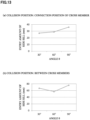
- FIG. 13 is a chart illustrating results of this simulation.
- the angle ⁇ when the corrugated plate portion is provided in the connection position of the side sill and the cross member is preferably 70 degrees or less.
- the angle ⁇ is more preferably 60 degrees or less.
- the angle ⁇ when the corrugated plate portion is provided between the cross members is preferably 40 to 80 degrees.
- the angle ⁇ is more preferably 50 degrees or more, and further, more preferably 70 degrees or less.
- the present invention can be applied to an automobile underbody structure.
Landscapes
- Engineering & Computer Science (AREA)
- Mechanical Engineering (AREA)
- Chemical & Material Sciences (AREA)
- Combustion & Propulsion (AREA)
- Transportation (AREA)
- Body Structure For Vehicles (AREA)
Abstract
Description
- The present invention relates to an automobile underbody structure.
- An automobile underbody structure constituted by structural members such as a side sill and a cross member requires energy absorption performance for absorbing an impact at collision time. As impact absorbing structures,
Patent Document 1 discloses a structure in which a zigzag-shaped connecting member is attached between a vehicle-body side portion and a chassis.Patent Document 2 discloses a bumper stay provided with an X-shaped reinforcing rib in the interior of a hollow portion having a front wall, a rear wall, and curved side walls. -
- Patent Document 1:
Japanese Laid-open Patent Publication No. 2002-087321 - Patent Document 2:
Japanese Laid-open Patent Publication No. 2006-335241 - A pole side impact test to evaluate the energy absorption performance by making a vehicle collide with a pole serves as an evaluation method of the energy absorption performance. In the pole side impact test, it is specified in advance which portion of the vehicle is made to collide with the pole. Thus, in the viewpoint of securing the energy absorption performance required as the automobile, the cross member is preferably disposed at a position brought into contact with the pole.
- On the other hand, in an actually occurring side collision of the automobile, the collision sometimes occurs at a point not provided with the cross member such as a point between two adjacent cross members. In such a side collision, not only the energy absorption performance but also restraint on an entry amount of the structural member such as the side sill into a vehicle-interior side is required for the underbody structure. In particular, a body layout in which a battery is mounted under a floor is employed for an electric vehicle in recent years, and thus a reduction in the entry amount of the structural member into the vehicle-interior side at collision time also leads to a further improvement in a protective function of the battery. Further, the problem associated with such entry of the structural member into the vehicle-interior side as described above arises not only for the side collision between the cross members but also, for example, similarly, at the time of collision with a bumper beam between front member sides. Accordingly, without being limited to any collision direction, a deformation of the structural member into the vehicle-interior side at collision time can be preferably restrained.
- However, the structure disclosed in
Patent Document 1 is a structure in which the zigzag-shaped connecting member transmits a collision load to the side sill, and is not a structure in which a deformation itself of the side sill is restrained. The bumper stay inPatent Document 2 functions as a crash box, and does not have a structure in which a deformation of structural members into the vehicle-interior side at collision time is restrained. - The present invention has been made in consideration of the above circumstances, and has an object to reduce the entry amount of the structural member into the vehicle-interior side at collision time.
- An aspect of the present invention for solving the above problems is an automobile underbody structure, the automobile underbody structure includes: a plurality of spaced first frame parts; a second frame part having a hollow portion extending so that an axial direction of the first frame part is a normal direction when seen from a vehicle height direction; and an impact absorbing member disposed in the hollow portion of the second frame part, wherein: the second frame part has a first wall portion and a second wall portion facing the first wall portion; the first wall portion is connected to vehicle-exterior end faces of the first frame parts in the axial direction; the impact absorbing member includes: a first beam portion extending along an axial direction of the second frame part; a second beam portion facing the first beam portion; and a corrugated plate portion connected to the first beam portion and the second beam portion between the first beam portion and the second beam portion, wherein: the first beam portion is connected to the first wall portion of the second frame part; the second beam portion is connected to the second wall portion of the second frame part; the corrugated plate portion includes: a first diagonal portion extending in a direction from the second beam portion toward the first beam portion; a second diagonal portion extending in a direction from the first beam portion toward the second beam portion; a first top portion which is a connection portion of the first diagonal portion and the second diagonal portion on the first beam portion side; and a second top portion which is a connection portion of the first diagonal portion and the second diagonal portion on the second beam portion side; and the corrugated plate portion is provided in at least respective regions, in the second frame part, to which the two adjacent first frame parts are connected.
- According to the present invention, it is possible to reduce an entry amount of a structural member into a vehicle-interior side at collision time.
-
-
FIG. 1 is a view illustrating one example of a body framework of an automobile. -
FIG. 2 is a view illustrating a schematic configuration of an automobile underbody structure according to a first embodiment of the present invention. -
FIG. 3 is a view illustrating a cross section taken along A-A inFIG. 2 . -
FIG. 4 is a perspective view illustrating an impact absorbing member of the first embodiment. -
FIG. 5 is an enlarged view of the impact absorbing member seen from a vehicle height direction. -
FIG. 6 is a view illustrating a disposition example of the impact absorbing member. -
FIG. 7 is a view illustrating a schematic configuration of an automobile underbody structure according to a second embodiment of the present invention. -
FIG. 8 is a perspective view illustrating an impact absorbing member of the second embodiment. -
FIG. 9 is a view illustrating a shape example of a corrugated plate portion. -
FIG. 10 is a view illustrating a shape example of a corrugated plate portion. -
FIG. 11 is diagrams illustrating analysis models of a pole side impact simulation (1), and deformed states of side sills after the simulation. -
FIG. 12 is diagrams illustrating analysis models of a pole side impact simulation (2), and deformed states of side sills after the simulation. -
FIG. 13 is a chart illustrating results of a pole side impact simulation (3). - Hereinafter, an embodiment of the present invention will be described while referring to the drawings. Note that in the present description and the drawings, elements having substantially the same functional configurations are denoted by the same codes to omit overlapped explanation.
-
FIG. 1 is a view illustrating one example of a body framework of an automobile. The body framework of the automobile includes, for example, a cross member (floor cross member) extending in a vehicle width direction, a side sill extending in a vehicle length direction, a bumper beam extending in the vehicle width direction, a side member extending in the vehicle length direction, and the like as illustrated inFIG. 1 . -
FIG. 2 is a view illustrating a schematic configuration of anunderbody structure 1 according to the first embodiment. Theunderbody structure 1 of this embodiment includes a plurality offirst frame parts 10 extending in an X direction and asecond frame part 20 extending in a Y direction. Note thatFIG. 2 is a view of theunderbody structure 1 being seen from a vehicle height direction (Z direction), and thus the "second frame part 20 extending in the Y direction" can also be reworded as thesecond frame part 20 extending so that an axial direction (extending direction) of thefirst frame part 10 is a normal direction when seen from the vehicle height direction. - The respective
first frame parts 10 are spaced along an axial direction of the second frame part 20 (Y direction). Further, thesecond frame part 20 is connected to vehicle-exterior end faces of thefirst frame parts 10. Thefirst frame parts 10 and thesecond frame part 20 may be directly connected to one another, or may be indirectly connected by providing some member between thefirst frame parts 10 and thesecond frame part 20. - The
first frame part 10 is a structural member such as, for example, a cross member and a side member, and a member which exhibits energy absorption performance or impact resistance performance when a collision load is input from the axial direction. When thefirst frame parts 10 are the cross members, thesecond frame part 20 is the side sill. The side sill extends so that the axial direction of the cross member (X direction) is the normal direction, and is connected to the vehicle-exterior end faces of the cross members. Thus, when thefirst frame parts 10 are the cross members, and thesecond frame part 20 is the side sill, the X direction in the present description and the drawings is the vehicle width direction, and the Y direction therein is the vehicle length direction. - On the other hand, when the
first frame parts 10 are the side members, thesecond frame part 20 is the bumper beam. The bumper beam extends so that the axial direction of the side member (X direction) is the normal direction, and is connected to the vehicle-exterior end faces of the side members with crash boxes therebetween. Thus, thefirst frame parts 10 are the side members, and thesecond frame part 20 is the bumper beam, the X direction in the present description and the drawings is the vehicle length direction, and the Y direction therein is the vehicle width direction. - Note that the side member may be a front side member or may be a rear side member. Further, the bumper beam may be a front bumper beam or may be a rear bumper beam. For example, when the
first frame parts 10 are the front side members, thesecond frame part 20 is the front bumper beam, and when thefirst frame parts 10 are the rear side members, thesecond frame part 20 is the rear bumper beam. - A shape and a material of the
first frame part 10 is not particularly limited as long as they are suitable as the structural member of theunderbody structure 1 of automobiles. For example, thefirst frame part 10, whose cross section perpendicular to the axial direction (X direction) is in a closed cross-sectional shape, is in a shape having a square tube-shaped hollow portion. Further, for example, as the material of thefirst frame part 10, a metallic material such as a steel sheet having, for example, a tensile strength of 590 MPa or more, a metallic material such as an aluminum alloy member or a magnesium alloy member, or the like can be employed. A length of thefirst frame part 10 in the axial direction is, for example, 500 to 1500 mm, and a plate thickness of thefirst frame part 10 is, for example, 1 to 5 mm. When the cross section perpendicular to the axial direction of thefirst frame part 10 is in a square tube shape, a section size of thefirst frame part 10 is, for example, 30 to 200 mm square. -
FIG. 3 is a view illustrating a cross section taken along A-A inFIG. 2 , and indicates a cross section perpendicular to the axial direction of the second frame part 20 (Y direction). Thesecond frame part 20 has ahollow portion 21 extending in the axial direction (Y direction). Thehollow portion 21 of this embodiment is formed by joining two members such as aninner member 22 and anouter member 23 to each other as illustrated inFIG. 3 . For this embodiment, theinner member 22 is a hat-shaped member including atop plate 22a, avertical wall 22b, and aflange 22c, and theouter member 23 is a hat-shaped member including atop plate 23a, avertical wall 23b, and aflange 23c. - Note that the
hollow portion 21 of this embodiment is formed of the two hat-shaped members, and for example, either member of the two hat-shaped members may be a flat plate. Further, thehollow portion 21 need not be limited to one formed by connecting a plurality of members, but may be formed by, for example, extrusion molding. Further, a shape of thehollow portion 21 on a cut surface perpendicular to the axial direction of thesecond frame part 20 is not limited to a square tube shape. - As a material of the
second frame part 20, the metallic material such as the steel sheet having, for example, the tensile strength of 590 MPa or more, the metallic material such as the aluminum alloy member or the magnesium alloy member, or the like can be employed. A length of thesecond frame part 20 in the axial direction (Y direction) is, for example, 1000 to 3000 mm, and a plate thickness of thesecond frame part 20 is, for example, 1 to 5 mm. When the cross section perpendicular to the axial direction of thesecond frame part 20 is in a square tube shape, a section size of thesecond frame part 20 is, for example, 50 to 200 mm square. - The
second frame part 20 includes afirst wall portion 20a and asecond wall portion 20b. Thefirst wall portion 20a and thesecond wall portion 20b face each other, and thefirst wall portion 20a is connected to the vehicle-exterior end faces of thefirst frame parts 10 in the axial direction (X direction). For this embodiment, thefirst wall portion 20a corresponds to thetop plate 22a of theinner member 22, and thesecond wall portion 20b corresponds to thetop plate 23a of theouter member 23. - The
underbody structure 1 includes animpact absorbing member 30 in thehollow portion 21 of thesecond frame part 20 as illustrated inFIG. 2 to FIG. 5 . Theimpact absorbing member 30 includes afirst beam portion 31, asecond beam portion 32, and acorrugated plate portion 33. - The
first beam portion 31 and thesecond beam portion 32 face each other, and thefirst beam portion 31 and thesecond beam portion 32 each extend along the axial direction of the second frame part 20 (Y direction). A length of each of thefirst beam portion 31 and thesecond beam portion 32 in the extending direction (Y direction) is at least longer than a distance between the two adjacentfirst frame parts 10, and thefirst beam portion 31 and thesecond beam portion 32 each have a length extending across the two adjacentfirst frame parts 10. Thefirst beam portion 31 of this embodiment is formed in a plate shape, and connected to thefirst wall portion 20a of thesecond frame part 20. Further, thesecond beam portion 32 of this embodiment is formed in a plate shape, and connected to thesecond wall portion 20b of thesecond frame part 20. - The
corrugated plate portion 33 is connected to thefirst beam portion 31 and thesecond beam portion 32 so as to extend across between thefirst beam portion 31 and thesecond beam portion 32. Thecorrugated plate portion 33 of this embodiment continuously extends along the axial direction of the second frame part 20 (Y direction). Thecorrugated plate portion 33 has a firstdiagonal portion 34, a seconddiagonal portion 35, a firsttop portion 36, and a secondtop portion 37. The firstdiagonal portion 34 extends in a direction from thesecond beam portion 32 toward thefirst beam portion 31, and the seconddiagonal portion 35 extends in a direction from thefirst beam portion 31 toward thesecond beam portion 32. The firsttop portion 36 and the secondtop portion 37 are each a portion to which the firstdiagonal portion 34 and the seconddiagonal portion 35 are connected, and the firsttop portion 36 is a connection portion on thefirst beam portion 31 side, and the secondtop portion 37 is a connection portion on thesecond beam portion 32 side. - The first
top portion 36 and the secondtop portion 37 of this embodiment are each formed in a flat-plate shape, the firsttop portion 36 is connected to thefirst beam portion 31, and the secondtop portion 37 is connected to thesecond beam portion 32. In this embodiment, each of the firsttop portion 36 and the secondtop portion 37 is present in plurality, and the firsttop portions 36 and the secondtop portions 37 are alternately positioned in the axial direction of thesecond frame part 20. Note that from the viewpoint of effectively reducing an entry amount of thesecond frame part 20 into the vehicle-interior side at collision time, all the firsttop portions 36 are preferably connected to thefirst beam portion 31, but as long as the position of thecorrugated plate portion 33 with respect to thefirst beam portion 31 can be fixed, not all the firsttop portions 36 need to be connected to thefirst beam portion 31. For example, some of the firsttop portions 36 are only required to be simply in contact with thefirst beam portion 31 or be in close proximity to thefirst beam portion 31 without being connected thereto. For the same reason, not all the secondtop portions 37 need to be connected to thesecond beam portion 32. - An angle θ made by the first
diagonal portion 34 and the second diagonal portion 35 (FIG. 5 ) is set optionally, and from the viewpoint of effectively restraining the entry amount of thesecond frame part 20 into the vehicle-interior side as presented in later-described examples, the angle θ when thecorrugated plate portion 33 is provided in a region, in thesecond frame part 20, to which thefirst frame part 10 is connected is preferably 70 degrees or less. The angle is more preferably 60 degrees or less. Further, the angle θ when thecorrugated plate portion 33 is provided between the adjacentfirst frame parts 10 is preferably 40 to 80 degrees. The angle θ in this case is preferably 50 degrees or more, and preferably 70 degrees or less. - As a material of the
first beam portion 31, thesecond beam portion 32, and thecorrugated plate portion 33, the metallic material such as the steel sheet having, for example, the tensile strength of 590 MPa or more, the metallic material such as the aluminum alloy member or the magnesium alloy member, or the like can be employed. Further, a plate thickness of each of thefirst beam portion 31, thesecond beam portion 32, and thecorrugated plate portion 33 is, for example, 1 to 10 mm. - Note that a connecting means of the
first beam portion 31 of theimpact absorbing member 30 and thefirst wall portion 20a of thesecond frame part 20, a connecting means of thesecond beam portion 32 of theimpact absorbing member 30 and thesecond wall portion 20b of thesecond frame part 20, a connecting means of thecorrugated plate portion 33 of theimpact absorbing member 30 and thefirst beam portion 31, a connecting means of thecorrugated plate portion 33 and thesecond beam portion 32, and the like are not particularly limited. For example, a mechanical joining means such as riveting, or a joining means such as arc welding or spot welding can be employed. Further, a shape of the firsttop portion 36 and the secondtop portion 37 is not limited to the flat-plate shape as in this embodiment, but appropriately changed depending on the employed connecting means. - In the
impact absorbing member 30 of this embodiment, thefirst beam portion 31, thesecond beam portion 32, and thecorrugated plate portion 33 are formed of respective separate members, but may be integrally molded by, for example, extrusion molding. Note that vehicle-height-direction lengths of thefirst beam portion 31, thesecond beam portion 32, and thecorrugated plate portion 33 are each appropriately changed depending on required energy absorption performance or a weight limit. - Further, a connection position of the
impact absorbing member 30 in the vehicle height direction (Z direction) with respect to the second frame part 20 (a height at which theimpact absorbing member 30 is disposed) is preferably positioned in a region, in thesecond frame part 20, in which thefirst frame parts 10 are connected. InFIG. 3 for example, theimpact absorbing member 30 is disposed in a middle portion in the vehicle height direction of thesecond frame part 20, and when thefirst frame part 10 is disposed in the vicinity of an upper end portion of thesecond frame part 20 as inFIG. 6 , theimpact absorbing member 30 is preferably also disposed in the vicinity of the upper end portion of thesecond frame part 20. - The
underbody structure 1 of this embodiment is constituted as described above. In theunderbody structure 1 as in this embodiment, when a collision load from the X direction is input to a region, of thesecond frame part 20, between the two adjacentfirst frame parts 10, the collision load can be easily distributed to a region other than a collision point by providing theimpact absorbing member 30. - In a detailed description, in the
impact absorbing member 30, providing thesecond beam portion 32 extending in the Y direction causes the collision load input from the X direction to thesecond frame part 20 to also spread in the Y direction in the course of a deformation of thesecond beam portion 32 and to be also transmitted to the firstdiagonal portions 34 and the seconddiagonal portions 35 in the region other than the collision point. Further, disposing the firstdiagonal portions 34 and the seconddiagonal portions 35 to be inclined in a manner to form an angle with each other causes the collision load transmitted to the firstdiagonal portions 34 and the seconddiagonal portions 35 to further spread in the Y direction. Further, the collision load transmitted from the firstdiagonal portions 34 or the seconddiagonal portions 35 to thefirst beam portion 31 further spreads in the Y direction in the course of a deformation of thefirst beam portion 31 similarly to thesecond beam portion 32. - According to the
impact absorbing member 30 included in theunderbody structure 1 of this embodiment, such a distribution of the collision load as described above at collision time also uses material portions in the region other than the collision point, which enables withstanding of the collision load. As a result, the entry amount of thesecond frame part 20 into the vehicle-interior side at collision time can be reduced. -
FIG. 7 is a view illustrating a schematic configuration of anunderbody structure 1 according to a second embodiment, andFIG. 8 is a perspective view of animpact absorbing member 30 of the second embodiment. In theimpact absorbing member 30 of this embodiment, a region in which acorrugated plate portion 33 is not provided in an extending direction of the impact absorbing member 30 (Y direction) is present. - In other words, the
impact absorbing member 30 includes a plurality ofcorrugated plate portions corrugated plate portions impact absorbing member 30. The respectivecorrugated plate portions second frame part 20, to whichfirst frame parts 10 are connected, and the region in which thecorrugated plate portion 33 is not provided is positioned between the two adjacentfirst frame part 10b andfirst frame part 10c. - In the
underbody structure 1 as in this embodiment, when a collision load is input to the region, of thesecond frame part 20, between the two adjacentfirst frame parts corrugated plate portions 33 connected by thesecond beam portion 32, to allow thecorrugated plate portions corrugated plate portion 33 is not provided, due to the absence of a firstdiagonal portion 34 and a seconddiagonal portion 35, thesecond beam portion 32 is easily deformed into a vehicle-interior side as compared with a case of the first embodiment. - In the region in which the
corrugated plate portion 33 is not provided, the absence of the firstdiagonal portion 34 and the seconddiagonal portion 35 which transmit the collision load from thesecond beam portion 32 to thefirst beam portion 31 makes it difficult that a deformation of thefirst beam portion 31 into the vehicle-interior side appears until thesecond beam portion 32 comes into contact with thefirst beam portion 31. Further, the collision load is not transmitted to the firstdiagonal portion 34 and the seconddiagonal portion 35 in this region, corresponding to which, the collision load spreads in a larger region of theimpact absorbing member 30 in the Y direction. - Thus, the larger region of the
impact absorbing member 30 in the Y direction can bear the collision load as compared with the case of the first embodiment. Further, the two adjacentcorrugated plate portions first beam portion 31 and thesecond beam portion 32 makes it possible to withstand the collision load. This allows thesecond beam portion 32 to sufficiently absorb impact until thesecond beam portion 32 comes into contact with thefirst beam portion 31, resulting in enabling a reduction in entry amount of thesecond frame part 20 into the vehicle-interior side even though the region in which thecorrugated plate portion 33 is not provided is present in theimpact absorbing member 30. - To effectively reduce the entry amount of the
second frame part 20 into the vehicle-interior side as described above, a firsttop portion 36 of thecorrugated plate portion 33 is preferably not positioned in a region, in thesecond frame part 20, between the twofirst frame parts 10 adjacent in the axial direction (Y direction). The reason is as follows. - When the collision load is input to a
second wall portion 20b of thesecond frame part 20, the collision load spreads to the firsttop portion 36, which causes thefirst wall portion 20a to be easily deformed in the vehicle-interior side at a point where the firsttop portion 36 is present. When thecorrugated plate portion 33 is provided continuously in the axial direction of thesecond frame part 20 as in the previously described first embodiment, the respective firsttop portions 36 are connected to one another with the firstdiagonal portions 34 and the seconddiagonal portions 35 therebetween, which easily distributes the collision load to the respective firsttop portions 36. This enables restraint on the deformation of thefirst wall portion 20a even at the points where the firsttop portions 36 are present. - On the other hand, in the case where the
corrugated plate portion 33 is not provided continuously in the axial direction of thesecond frame part 20, for example, when the firsttop portion 36 is positioned in the region between the twofirst frame parts 10, the collision load is easily concentrated on the firsttop portion 36 closest to a collision point, which easily deforms thefirst wall portion 20a into the vehicle-interior side at this point. In contrast to this, as long as thecorrugated plate portions 33 are disposed so as not to position the firsttop portion 36 between the twofirst frame parts 10 as in the second embodiment, the deformation of thefirst wall portion 20a into the vehicle-interior side at the points where the firsttop portions 36 are present is restrained by thefirst frame parts 10. This also enables restraint on a deformation as the entirefirst wall portion 20a into the vehicle-interior side. - Note that in this embodiment, the region in which the
corrugated plate portion 33 is not provided is positioned between thefirst frame part 10b and thefirst frame part 10c illustrated inFIG. 7 , and may be positioned between thefirst frame part 10a and thefirst frame part 10b, or may be positioned in each of all intervals from thefirst frame part 10a to thefirst frame part 10c. In any case, the firsttop portion 36 of thecorrugated plate portion 33 is preferably not positioned in the region between the two adjacentfirst frame parts 10. - Further, the
corrugated plate portion 33 of theimpact absorbing member 30 can reduce the entry amount of thesecond frame part 20 into the vehicle-interior side even though it is not provided between the two adjacentfirst frame parts 10 as described in this embodiment. Thus, thecorrugated plate portions 33 only need to be provided in at least the regions R, in thesecond frame part 20, to which the two adjacentfirst frame parts 10 are connected. For example, thecorrugated plate portions 33 may be provided as inFIG. 9 . In an example inFIG. 9 , the onecorrugated plate portion 33 is provided with one each of the firstdiagonal portion 34 and the seconddiagonal portion 35, and the firsttop portion 36 and secondtop portions 37 are at three points in total. - Further, for example, the
corrugated plate portions 33 may be provided as inFIG. 10 . In an example inFIG. 10 , the onecorrugated plate portion 33 is provided with two each of the firstdiagonal portion 34 and the seconddiagonal portion 35, and the firsttop portions 36 and the secondtop portions 37 are at five points in total. In the viewpoint of effectively improving energy absorption performance, it is preferable that each of thecorrugated plate portions 33 is provided with the plurality of firstdiagonal portions 34 and seconddiagonal portions 35, and has the firsttop portions 36 and the secondtop portions 37 at five points or more in total as inFIG. 10 . - Although one example of an embodiment of the present invention has been described above, the present invention is not limited to such an example. It should be understood that various changes or modifications are readily apparent to those skilled in the art within the scope of the technical spirit as set forth in claims, and those should also be covered by the technical scope of the present invention as a matter of course.
- In the above-described embodiment, for example, only one row of the
corrugated plate portions 33 of theimpact absorbing member 30 extending in the axial direction of the second frame part 20 (Y direction) is provided, and a plurality of rows of theimpact absorbing members 30 extending in the Y direction may be disposed in parallel side by side along the axial direction of the first frame part 10 (X direction). - A pole side impact simulation was carried out by using analysis models of underbody structures of a
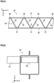
structure 1 and astructure 2 illustrated inFIG. 11 . First frame parts are cross members, and a second frame part is a side sill in this examples. Thestructure 1 is the model in which a corrugated plate portion is provided across the entire region of an impact absorbing member in an extending direction. Thestructure 2 is the model in which the corrugated plate portion is not provided between the cross members. Further, thestructure 2 is the same model as thestructure 1 except that regions in which the corrugated plate portions are provided are different. - In this simulation, a pole was entered into a vehicle-exterior wall portion of the side sill at a constant speed, and a deformed state and an entry amount of the vehicle-interior wall portion of the side sill in each of the structures at this time were evaluated. In the simulation for the
structure 1, the simulation in a case of making the pole collide at each position of a position to which the cross member is connected and a position between the cross members is carried out. In the simulation for thestructure 2, the simulation in a case of making the pole collide at a position between the cross members is carried out. - This simulation is carried out by using a plurality of models in which plate thicknesses of a beam portion (a first beam portion and a second beam portion) and plate thicknesses of the corrugated plate portion are varied. Conditions such as a material, the plate thicknesses, and the like of the impact absorbing member are as in the following Table 1. An angle θ made by a first diagonal portion and a second diagonal portion (
FIG. 5 ) is set to 60 degrees in this simulation. Note that a material of the cross member and the side sill is presumed to be a steel sheet having a tensile strength of 980 MPa grade similarly to the impact absorbing member. Table 1 also presents the entry amounts of the vehicle-interior wall portion of the side sill (deformation amounts at a point having the largest deformation into the vehicle-interior side) as simulation results.[Table 1] Impact absorbing member Entry amount of vehicle-interior wall portion of side sill (mm) Material Tensile strength (MPa) Plate thickness of beam portion (mm) Corrugated plate portion Weight (ratio with respect to structure 1) Collision position: connection position of cross member Collision position between cross members Plate thickness (mm) Angle θ Structure 1Steel sheet 980 7.6 5.2 60 degrees - 40 56 7.0 5.8 34 56 6.4 6.4 29 57 5.8 7.0 28 60 52 7.6 27 61 Structure 2Steel sheet 980 7.6 5.2 60 degrees 88.70% - 46 7.0 5.8 87.20% - 43 6.4 6.4 85.60% - 42 5.8 7.0 84.10% - 41 5.2 7.6 82.60% - 44 - As indicated by the results in Table 1, the models of the
structure 2 not provided with the corrugated plate portion between the cross members were more reduced in the entry amount of the side sill into the vehicle-interior side than those of thestructure 1 provided with the corrugated plate portion across the entire region of the impact absorbing member in the extending direction. A glance at the deformed states of thestructure 1 and thestructure 2 illustrated inFIG. 11 also shows that thestructure 2 has a larger deformed region of the side sill in the axial direction. Further, in this simulation, a weight of each of the models of thestructure 2 is reduced by about 10 to 20% with respect to each of the models of thestructure 1. Accordingly, as indicated by the results of this simulation, the structure not provided with the corrugated plate portion between the cross members enables the reduction in the entry amount of the side sill into the vehicle-interior side, and also enables a reduction in weight of the impact absorbing member. - As illustrated in
FIG. 12 , a pole side impact simulation was carried out withstructures 3 to 5 in which distances D between the corrugated plate portions of thestructure 2 in the simulation (1) were varied. Note that thestructure 1 and thestructure 2 illustrated inFIG. 12 are the same structures as the simulation (1). Thestructure 3 has the narrowest distance D, and the distance D is gradually increased in order of thestructure 3, thestructure 4, thestructure 5, and thestructure 2. Of thestructures 2 to 5, thestructure 2 is the model in which the firsttop portion 36 of the corrugated plate portion is not positioned between the two adjacent cross members, and thestructures 3 to 5 are each a model in which the firsttop portion 36 of at least one corrugated plate portion of the two corrugated plate portions is positioned between the two cross members. The simulation is carried out on thestructures 1 to 5 under the same conditions except that the distances D between the corrugated plate portions are different. - In focusing attention on deformed states after collision in the
structure 3 to thestructure 5 illustrated inFIG. 12 , deformation amounts at points at each of which the firsttop portion 36 of the corrugated plate portion is positioned between the cross members are large, and entry amounts of the side sills are a little large with respect to thestructure 1. On the other hand, in thestructure 2 in which the firsttop portions 36 of the corrugated plate portion are positioned in regions, in the side sill, to which the cross members are connected, a deformation of the side sill is restrained, resulting in a large decrease in the entry amount of the side sill with respect to the other structures. According to a result of this simulation, when the corrugated plate portion is not provided between the cross members, it is found preferable that the firsttop portion 36 of the corrugated plate portion is not positioned between the cross members. - A pole side impact simulation was carried out by using models in which angles θ made by a first diagonal portion and a second diagonal portion (
FIG. 5 ) were varied. The model having an angle θ of 30 degrees, the model having an angle θ of 60 degrees, and the model having an angle θ of 90 degrees are used in this simulation. Note that the model having the angle θ of 60 degrees is the same model as thestructure 1. The models having the angles θ of 30 degrees and 60 degrees are the same model as thestructure 1 except that the angles are different. -
FIG. 13 is a chart illustrating results of this simulation. As illustrated inFIG. 13(a) , in the models in each of which a corrugated plate portion is provided in a connection position of a side sill and a cross member, the smaller the angle θ was, the more an entry amount of the side sill was restrained. According to a result of this simulation, the angle θ when the corrugated plate portion is provided in the connection position of the side sill and the cross member is preferably 70 degrees or less. The angle θ is more preferably 60 degrees or less. Further, as illustrated inFIG. 13(b) , in the models in each of which the corrugated plate portion is provided between the cross members, the closer the angle θ was to 60 degrees, the more the entry amount of the side sill was restrained. According to a result of this simulation, the angle θ when the corrugated plate portion is provided between the cross members is preferably 40 to 80 degrees. The angle θ is more preferably 50 degrees or more, and further, more preferably 70 degrees or less. - The present invention can be applied to an automobile underbody structure.
-
- 1
- underbody structure
- 10
- first frame part
- 20
- second frame part
- 20a
- first wall portion
- 20b
- second wall portion
- 21
- hollow portion
- 22
- inner member
- 22a
- top plate
- 22b
- vertical wall
- 22c
- flange
- 23
- outer member
- 23a
- top plate
- 23b
- vertical wall
- 23c
- flange
- 30
- impact absorbing member
- 31
- first beam portion
- 32
- second beam portion
- 33
- corrugated plate portion
- 34
- first diagonal portion
- 35
- second diagonal portion
- 36
- first top portion
- 37
- second top portion
- D
- distance between two adjacent corrugated plate portions
- R
- region, in second frame part, to which first frame is connected
- θ
- angle made by first diagonal portion and second diagonal portion
Claims (5)
- An automobile underbody structure comprising:a plurality of spaced first frame parts;a second frame part having a hollow portion extending so that an axial direction of the first frame part is a normal direction when seen from a vehicle height direction; andan impact absorbing member disposed in the hollow portion of the second frame part, wherein:the second frame part has a first wall portion and a second wall portion facing the first wall portion;the first wall portion is connected to vehicle-exterior end faces of the first frame parts in the axial direction;the impact absorbing member includes:a first beam portion extending along an axial direction of the second frame part;a second beam portion facing the first beam portion; anda corrugated plate portion connected to the first beam portion and the second beam portion between the first beam portion and the second beam portion, wherein:the first beam portion is connected to the first wall portion of the second frame part;the second beam portion is connected to the second wall portion of the second frame part;the corrugated plate portion includes:a first diagonal portion extending in a direction from the second beam portion toward the first beam portion;a second diagonal portion extending in a direction from the first beam portion toward the second beam portion;a first top portion which is a connection portion of the first diagonal portion and the second diagonal portion on the first beam portion side; anda second top portion which is a connection portion of the first diagonal portion and the second diagonal portion on the second beam portion side; andthe corrugated plate portion is provided in at least respective regions, in the second frame part, to which the two adjacent first frame parts are connected.
- The automobile underbody structure according to claim 1, wherein
the impact absorbing member includes a plurality of the corrugated plate portions, wherein:the respective corrugated plate portions are spaced along an extending direction of the impact absorbing member; andthe first top portion of the corrugated plate portion is not positioned in a region between the two adjacent first frame parts. - The automobile underbody structure according to claim 1 or 2, wherein the first top portions and the second top portions are at five points or more in total.
- The automobile underbody structure according to any one of claims 1 to 3, wherein the second frame part is a side sill.
- The automobile underbody structure according to any one of claims 1 to 3, wherein the second frame part is a bumper beam.
Applications Claiming Priority (2)
| Application Number | Priority Date | Filing Date | Title |
|---|---|---|---|
| JP2020199652 | 2020-12-01 | ||
| PCT/JP2021/044145 WO2022118897A1 (en) | 2020-12-01 | 2021-12-01 | Vehicle body lower structure of automobile |
Publications (2)
| Publication Number | Publication Date |
|---|---|
| EP4230508A1 true EP4230508A1 (en) | 2023-08-23 |
| EP4230508A4 EP4230508A4 (en) | 2024-04-17 |
Family
ID=81853935
Family Applications (1)
| Application Number | Title | Priority Date | Filing Date |
|---|---|---|---|
| EP21900648.3A Pending EP4230508A4 (en) | 2020-12-01 | 2021-12-01 | LOWER STRUCTURE OF A VEHICLE BODY OF A MOTOR VEHICLE |
Country Status (6)
| Country | Link |
|---|---|
| US (1) | US12583521B2 (en) |
| EP (1) | EP4230508A4 (en) |
| JP (1) | JP7436934B2 (en) |
| KR (1) | KR102869570B1 (en) |
| CN (1) | CN116568568B (en) |
| WO (1) | WO2022118897A1 (en) |
Cited By (1)
| Publication number | Priority date | Publication date | Assignee | Title |
|---|---|---|---|---|
| EP4574495A1 (en) * | 2023-12-22 | 2025-06-25 | Toyota Jidosha Kabushiki Kaisha | Vehicle lower body structure |
Families Citing this family (1)
| Publication number | Priority date | Publication date | Assignee | Title |
|---|---|---|---|---|
| DE102019128374A1 (en) * | 2019-10-21 | 2021-04-22 | Bayerische Motoren Werke Aktiengesellschaft | Cross member arrangement for a battery electric motor vehicle |
Family Cites Families (16)
| Publication number | Priority date | Publication date | Assignee | Title |
|---|---|---|---|---|
| FR2315039A1 (en) * | 1975-06-20 | 1977-01-14 | Berliet Automobiles | ENERGY ABSORPTION DEVICE, ESPECIALLY FOR VEHICLES |
| US4221413A (en) * | 1978-02-28 | 1980-09-09 | Yves Bonnetain | Shock absorption bumper for an automotive vehicle |
| JPS6223322Y2 (en) * | 1980-12-19 | 1987-06-13 | ||
| JP3525731B2 (en) * | 1998-03-31 | 2004-05-10 | マツダ株式会社 | Body frame structure |
| JP2002087321A (en) | 2000-09-14 | 2002-03-27 | Toshiaki Ichikawa | Shock-absorbing car body and automobile |
| KR100770504B1 (en) * | 2001-09-12 | 2007-10-25 | 제너럴 일렉트릭 캄파니 | Shock-Resistant Bumper Systems, Beams for Bumper Assemblies, and Bumper Assemblies for Automotives |
| FR2859693B1 (en) * | 2003-09-11 | 2006-02-10 | Plastic Omnium Cie | BASS OF BODY FOR MOTOR VEHICLE |
| JP2006282106A (en) * | 2005-04-04 | 2006-10-19 | Toyota Motor Corp | Body frame reinforcement structure |
| JP2006335241A (en) | 2005-06-02 | 2006-12-14 | Kobe Steel Ltd | Bumper stay and bumper device |
| EP2213553A4 (en) * | 2007-10-24 | 2011-04-20 | Toyota Motor Co Ltd | STRUCTURE FOR SIDE PART OF VEHICLE BODYWORK |
| JP2010195352A (en) * | 2009-02-27 | 2010-09-09 | Toyota Motor Corp | Skeleton structure of vehicle |
| US9302638B2 (en) * | 2010-10-29 | 2016-04-05 | Sabic Global Technologies B.V. | Unitary energy absorbing assembly and method of making the same |
| CN204688021U (en) * | 2015-06-01 | 2015-10-07 | 北京汽车股份有限公司 | A kind of body structure structure and automobile |
| JP6276237B2 (en) * | 2015-10-19 | 2018-02-07 | 本田技研工業株式会社 | Body front structure |
| SE541218C2 (en) * | 2017-09-20 | 2019-05-07 | Gestamp Hardtech Ab | A vehicle side structure |
| WO2020085385A1 (en) * | 2018-10-24 | 2020-04-30 | 日本製鉄株式会社 | Automobile structural member |
-
2021
- 2021-12-01 CN CN202180080649.7A patent/CN116568568B/en active Active
- 2021-12-01 WO PCT/JP2021/044145 patent/WO2022118897A1/en not_active Ceased
- 2021-12-01 US US18/038,873 patent/US12583521B2/en active Active
- 2021-12-01 JP JP2022566964A patent/JP7436934B2/en active Active
- 2021-12-01 KR KR1020237021030A patent/KR102869570B1/en active Active
- 2021-12-01 EP EP21900648.3A patent/EP4230508A4/en active Pending
Cited By (1)
| Publication number | Priority date | Publication date | Assignee | Title |
|---|---|---|---|---|
| EP4574495A1 (en) * | 2023-12-22 | 2025-06-25 | Toyota Jidosha Kabushiki Kaisha | Vehicle lower body structure |
Also Published As
| Publication number | Publication date |
|---|---|
| JPWO2022118897A1 (en) | 2022-06-09 |
| KR102869570B1 (en) | 2025-10-14 |
| EP4230508A4 (en) | 2024-04-17 |
| JP7436934B2 (en) | 2024-02-22 |
| US20240025480A1 (en) | 2024-01-25 |
| US12583521B2 (en) | 2026-03-24 |
| CN116568568B (en) | 2025-09-12 |
| CN116568568A (en) | 2023-08-08 |
| KR20230109737A (en) | 2023-07-20 |
| WO2022118897A1 (en) | 2022-06-09 |
Similar Documents
| Publication | Publication Date | Title |
|---|---|---|
| US11572103B2 (en) | Rocker structure for a vehicle and method for obtaining thereof | |
| JP6703322B1 (en) | Vehicle frame members and electric vehicles | |
| US10442467B2 (en) | Central part structure for vehicle | |
| US20240097256A1 (en) | Battery case of automobile and method for manufacturing the same | |
| CN108495777A (en) | Front part structure of vehicle | |
| KR20220151799A (en) | Vehicle body | |
| US12583521B2 (en) | Automobile underbody structure | |
| CN114475793B (en) | Body structure and vehicle | |
| EP3932750A1 (en) | Structural member for vehicle | |
| CN220842679U (en) | Subframe of a vehicle, body component of a vehicle, and vehicle | |
| CN216994523U (en) | Cabin boundary beam and side wall connection structure and car | |
| CN117841625A (en) | Vehicle door and vehicle | |
| CN223905128U (en) | Threshold stiffening beam, threshold assembly, vehicle body structure and vehicle | |
| JP7609214B1 (en) | Electric vehicle underbody structure | |
| CN218021831U (en) | Longeron assembly and vehicle | |
| JP7726315B1 (en) | Electric vehicle underbody structure | |
| CN223370791U (en) | Longitudinal beam and vehicle | |
| JP7567964B1 (en) | Electric vehicle underbody structure | |
| CN222136862U (en) | Threshold structure and vehicle | |
| EP4682029A1 (en) | Vehicular shock absorbing member and side sill structure | |
| CN113276951B (en) | Front vehicle body energy absorption structure and new energy vehicle | |
| JP7567962B1 (en) | Electric vehicle underbody structure | |
| WO2025130110A1 (en) | Front subframe and vehicle | |
| JP2024150790A (en) | Electric vehicle underbody structure | |
| CA3281070A1 (en) | Impact absorbing member for vehicle and side sill structure |
Legal Events
| Date | Code | Title | Description |
|---|---|---|---|
| STAA | Information on the status of an ep patent application or granted ep patent |
Free format text: STATUS: THE INTERNATIONAL PUBLICATION HAS BEEN MADE |
|
| PUAI | Public reference made under article 153(3) epc to a published international application that has entered the european phase |
Free format text: ORIGINAL CODE: 0009012 |
|
| STAA | Information on the status of an ep patent application or granted ep patent |
Free format text: STATUS: REQUEST FOR EXAMINATION WAS MADE |
|
| 17P | Request for examination filed |
Effective date: 20230517 |
|
| AK | Designated contracting states |
Kind code of ref document: A1 Designated state(s): AL AT BE BG CH CY CZ DE DK EE ES FI FR GB GR HR HU IE IS IT LI LT LU LV MC MK MT NL NO PL PT RO RS SE SI SK SM TR |
|
| DAV | Request for validation of the european patent (deleted) | ||
| DAX | Request for extension of the european patent (deleted) | ||
| A4 | Supplementary search report drawn up and despatched |
Effective date: 20240319 |
|
| RIC1 | Information provided on ipc code assigned before grant |
Ipc: B62D 25/04 20060101ALI20240313BHEP Ipc: B62D 25/02 20060101ALI20240313BHEP Ipc: B62D 21/15 20060101ALI20240313BHEP Ipc: B60R 19/18 20060101ALI20240313BHEP Ipc: B62D 25/20 20060101AFI20240313BHEP |
|
| GRAP | Despatch of communication of intention to grant a patent |
Free format text: ORIGINAL CODE: EPIDOSNIGR1 |
|
| STAA | Information on the status of an ep patent application or granted ep patent |
Free format text: STATUS: GRANT OF PATENT IS INTENDED |
|
| INTG | Intention to grant announced |
Effective date: 20250829 |
|
| STAA | Information on the status of an ep patent application or granted ep patent |
Free format text: STATUS: THE APPLICATION IS DEEMED TO BE WITHDRAWN |