EP4230487A1 - Braking device and spare brake control device - Google Patents
Braking device and spare brake control device Download PDFInfo
- Publication number
- EP4230487A1 EP4230487A1 EP23153901.6A EP23153901A EP4230487A1 EP 4230487 A1 EP4230487 A1 EP 4230487A1 EP 23153901 A EP23153901 A EP 23153901A EP 4230487 A1 EP4230487 A1 EP 4230487A1
- Authority
- EP
- European Patent Office
- Prior art keywords
- brake
- spare
- electric motor
- power supply
- electricity
- Prior art date
- Legal status (The legal status is an assumption and is not a legal conclusion. Google has not performed a legal analysis and makes no representation as to the accuracy of the status listed.)
- Granted
Links
Images



Classifications
-
- B—PERFORMING OPERATIONS; TRANSPORTING
- B60—VEHICLES IN GENERAL
- B60T—VEHICLE BRAKE CONTROL SYSTEMS OR PARTS THEREOF; BRAKE CONTROL SYSTEMS OR PARTS THEREOF, IN GENERAL; ARRANGEMENT OF BRAKING ELEMENTS ON VEHICLES IN GENERAL; PORTABLE DEVICES FOR PREVENTING UNWANTED MOVEMENT OF VEHICLES; VEHICLE MODIFICATIONS TO FACILITATE COOLING OF BRAKES
- B60T8/00—Arrangements for adjusting wheel-braking force to meet varying vehicular or ground-surface conditions, e.g. limiting or varying distribution of braking force
- B60T8/17—Using electrical or electronic regulation means to control braking
- B60T8/1701—Braking or traction control means specially adapted for particular types of vehicles
- B60T8/1705—Braking or traction control means specially adapted for particular types of vehicles for rail vehicles
-
- B—PERFORMING OPERATIONS; TRANSPORTING
- B60—VEHICLES IN GENERAL
- B60T—VEHICLE BRAKE CONTROL SYSTEMS OR PARTS THEREOF; BRAKE CONTROL SYSTEMS OR PARTS THEREOF, IN GENERAL; ARRANGEMENT OF BRAKING ELEMENTS ON VEHICLES IN GENERAL; PORTABLE DEVICES FOR PREVENTING UNWANTED MOVEMENT OF VEHICLES; VEHICLE MODIFICATIONS TO FACILITATE COOLING OF BRAKES
- B60T13/00—Transmitting braking action from initiating means to ultimate brake actuator with power assistance or drive; Brake systems incorporating such transmitting means, e.g. air-pressure brake systems
- B60T13/74—Transmitting braking action from initiating means to ultimate brake actuator with power assistance or drive; Brake systems incorporating such transmitting means, e.g. air-pressure brake systems with electrical assistance or drive
-
- B—PERFORMING OPERATIONS; TRANSPORTING
- B60—VEHICLES IN GENERAL
- B60T—VEHICLE BRAKE CONTROL SYSTEMS OR PARTS THEREOF; BRAKE CONTROL SYSTEMS OR PARTS THEREOF, IN GENERAL; ARRANGEMENT OF BRAKING ELEMENTS ON VEHICLES IN GENERAL; PORTABLE DEVICES FOR PREVENTING UNWANTED MOVEMENT OF VEHICLES; VEHICLE MODIFICATIONS TO FACILITATE COOLING OF BRAKES
- B60T17/00—Component parts, details, or accessories of power brake systems not covered by groups B60T8/00, B60T13/00 or B60T15/00, or presenting other characteristic features
-
- B—PERFORMING OPERATIONS; TRANSPORTING
- B60—VEHICLES IN GENERAL
- B60T—VEHICLE BRAKE CONTROL SYSTEMS OR PARTS THEREOF; BRAKE CONTROL SYSTEMS OR PARTS THEREOF, IN GENERAL; ARRANGEMENT OF BRAKING ELEMENTS ON VEHICLES IN GENERAL; PORTABLE DEVICES FOR PREVENTING UNWANTED MOVEMENT OF VEHICLES; VEHICLE MODIFICATIONS TO FACILITATE COOLING OF BRAKES
- B60T2270/00—Further aspects of brake control systems not otherwise provided for
- B60T2270/40—Failsafe aspects of brake control systems
-
- F—MECHANICAL ENGINEERING; LIGHTING; HEATING; WEAPONS; BLASTING
- F16—ENGINEERING ELEMENTS AND UNITS; GENERAL MEASURES FOR PRODUCING AND MAINTAINING EFFECTIVE FUNCTIONING OF MACHINES OR INSTALLATIONS; THERMAL INSULATION IN GENERAL
- F16D—COUPLINGS FOR TRANSMITTING ROTATION; CLUTCHES; BRAKES
- F16D2121/00—Type of actuator operation force
- F16D2121/18—Electric or magnetic
- F16D2121/24—Electric or magnetic using motors
Definitions
- the present invention relates to a braking technology for railroad vehicles.
- Patent Literature 1 discloses an electric brake actuator including a service brake mechanism unit that uses rotational power of a motor to drive a push rod equipped with a friction material that is pressed against a wheel of a railroad vehicle, and a spare brake mechanism unit that uses spring force to move the push rod.
- the spare brake mechanism unit activates the spare brake by means of the push rod that is moved by the force of a pressurized spring, so as to safely stop the railroad vehicle. Then, after recovery from the power failure, the service brake mechanism unit is operated such as to generate the maximum brake force, and the spring is pressurized again by means of the reaction force.
- Patent Literature 1 Japanese Translation of PCT International Application Publication No. 2001-521468
- the present invention has been made in view of such a situation, and a purpose thereof is to provide a braking device and the like that can reduce the workload related to the operation of a spare brake when a service brake cannot be used.
- a braking device includes: a brake mechanism that presses a friction material against a braking target member of a railroad vehicle to brake the railroad vehicle; a spare electric motor that drives the brake mechanism and that is different from a regular electric motor; a spare power supply that supplies electricity to the spare electric motor and that is different from a regular power supply; and an electricity supply controller that controls supply of electricity from the spare power supply to the spare electric motor in response to a spare brake command.
- the spare brake can be operated with the spare electric motor and the spare power supply.
- the spare brake control device includes: a spare power supply that is different from a regular power supply; a spare electric motor that drives a friction material, which is pressed against a braking target member of a railroad vehicle to brake the railroad vehicle, based on electricity supplied from the spare power supply and that is different from a regular electric motor; and an electricity supply controller that controls supply of electricity from the spare power supply to the spare electric motor in response to a spare brake command.
- the present invention reduces the workload related to the operation of a spare brake when a service brake cannot be used.
- FIG. 1 schematically illustrates a configuration of a braking device 1 according to a first embodiment.
- the braking device 1 includes a brake mechanism 2, a service brake unit 3, and a spare brake unit 4 as a spare brake control device.
- the spare brake is sometimes referred to as a security brake, a backup brake, or an emergency brake.
- the service brake unit 3 and the spare brake unit 4 are controlled by commands from a brake command unit or a control unit 5.
- the brake mechanism 2 which constitutes a tread brake, includes a shoe 21 as a friction material that is pressed against a wheel, which is a braking target member in a railroad vehicle, to brake the railroad vehicle.
- the shoe 21 faces at least part of the outer circumference of the wheel, and, on the facing surface (inner circumference surface), brake lining or the like is provided.
- the shoe 21 is driven in a radial direction of the wheel by the service brake unit 3 or the spare brake unit 4 and, when the shoe 21 reaches a brake action position where it comes into contact with the wheel and is then pressed, the frictional force between the brake lining or the like and the wheel slows the rotation of the wheel to brake the railroad vehicle.
- the brake mechanism 2 may also be configured as a disc brake, and pads may be provided as the friction material instead of the shoe 21 used in a tread brake.
- the pads sandwich a brake disc, which rotates integrally with a wheel, from both sides in a rotational axis direction, and, on the surface of each pad that faces the brake disc, brake lining or the like is provided.
- the pads are driven in the rotational axis directions of the wheel by the service brake unit 3 or the spare brake unit 4 and, when the pads reach the brake action position where the pads come into contact with the brake disc from both sides and are then pressed, the frictional force between the brake lining or the like and the brake disc slows the rotation of the wheel to brake the railroad vehicle.
- the brake mechanism 2 may also be configured as any other arbitrary type of brake, such as a drum brake.
- the brake mechanism 2 further includes a power transmission mechanism 22 connected to the service brake unit 3 and the spare brake unit 4.
- the power transmission mechanism 22 transmits the power of the service brake unit 3 to the shoe 21, and, when the service brake unit 3 is not functioning, the power transmission mechanism 22 transmits the power of the spare brake unit 4 to the shoe 21.
- the power transmission mechanism 22 preferentially transmits the power of the service brake unit 3 to the shoe 21 and transmits, only when the service brake unit 3 is not functioning, the power of the spare brake unit 4 to the shoe 21.
- the power transmission mechanism 22 may be configured by a combination of publicly-known mechanical elements, such as a clutch and Torque Diode (trademark).
- the power transmission mechanism 22 may be equipped with a booster mechanism, such as a toggle mechanism, that amplifies rotational power generated by the motors of the service brake unit 3 and the spare brake unit 4, and a reduction mechanism that obtains torque corresponding to the reduction ratio of the rotational power.
- the power transmission mechanism 22 also includes a rotational-linear transformation mechanism that transforms the rotational power generated by the motors of the service brake unit 3 and the spare brake unit 4 into linear power used to drive the shoe 21 in the radial direction.
- the service brake unit 3 includes a vehicle power supply 31 as a regular power supply, a control circuit 32, and a motor 33 as a regular electric motor.
- the vehicle power supply 31 may be provided outside the service brake unit 3 or even outside the braking device 1.
- the vehicle power supply 31 may supply the control circuit 32 with electricity supplied from a pantograph to the railroad vehicle.
- the vehicle power supply 31 mounted on at least one railroad vehicle supplies alternating-current (AC) or direct-current (DC) electricity supplied through a train line, such as an overhead train line (overhead line) and a power feed rail (third rail), to various equipment and devices of the railroad vehicle, including the control circuit 32 and the motor 33.
- AC alternating-current
- DC direct-current
- the control circuit 32 includes an inverter for generating multiphase AC electricity of desired frequency and amplitude based on the electricity supplied from the vehicle power supply 31, so as to generate AC electricity, such as three-phase AC electricity, to be applied to the motor 33 in response to a service brake command from the vehicle cab as the control unit 5.
- the motor 33 as the regular electric motor is an AC motor, which drives the shoe 21 based on the AC electricity generated by the control circuit 32 in response to a service brake command from the control unit 5.
- the service brake commands from the vehicle cab as the control unit 5 are broadly classified into a service brake action command issued to drive the shoe 21 to the brake action position where the shoe 21 is pressed against the wheel, and a service brake release command issued to drive the shoe 21 to a brake release position where the shoe 21 is not pressed against the wheel.
- the control circuit 32 rotates the rotor of the motor 33 in a first direction (hereinafter, also referred to as an action direction or a normal rotation direction) to generate a first alternating current (hereinafter, also referred to as an action alternating current or a normal rotation alternating current) to drive the shoe 21 to the brake action position.
- the control circuit 32 rotates the rotor of the motor 33 in a second direction (hereinafter, also referred to as a release direction or a reverse rotation direction), which is opposite to the first direction, to generate a second alternating current (hereinafter, also referred to as a release alternating current or a reverse rotation alternating current) to drive the shoe 21 to the brake release position.
- a second direction hereinafter, also referred to as a release direction or a reverse rotation direction
- a second alternating current hereinafter, also referred to as a release alternating current or a reverse rotation alternating current
- the control circuit 32, and the motor 33 are functioning properly, the control of action and release of the brake, i.e., driving of the shoe 21 between the brake action position and the brake release position, is performed by the service brake unit 3.
- the control circuit 32, or the motor 33 is not functioning properly, the control of action and release of the brake, i.e., driving of the shoe 21 between the brake action position and the brake release position, is performed by the spare brake unit 4.
- the spare brake unit 4 constitutes a spare brake drive device that drives, when the service brake unit 3 is unable to drive the shoe 21 placed at the brake action position to the brake release position, the shoe 21 to the brake release position in response to a spare brake release command (shown as "RELEASE COMMAND" in FIG. 1 ) from the control unit 5. More specifically, when the service brake unit 3 is not functioning, the spare brake unit 4 drives the shoe 21 between the brake action position and the brake release position, based on DC electricity supplied from a battery 41 as a spare power supply.
- the spare brake unit 4 includes the battery 41, a relay circuit 42 as an electricity supply controller, and a DC motor 43 as a spare electric motor and a DC electric motor.
- the battery 41 different from the vehicle power supply 31, supplies DC electricity.
- the relay circuit 42 supplies the DC electricity from the battery 41 to the DC motor 43, in response to a spare brake command as a spare brake action command and a spare brake release command from the control unit 5.
- the DC motor 43 drives the shoe 21 between the brake action position and the brake release position, based on the DC electricity supplied from the battery 41 via the relay circuit 42.
- the DC motor 43 may be constituted by an inverter that converts the DC electricity supplied from the relay circuit 42 into AC electricity, and by an electric motor, similar to the regular electric motor (motor 33), that generates rotational power based on the AC electricity converted by the inverter.
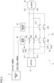
- FIG. 2 schematically illustrates the details of the relay circuit 42.
- the first path 44 includes a high potential line 441 connected to a high potential terminal 411 of the battery 41, and a low potential line 442 connected to a low potential terminal 412 of the battery 41.
- the high potential line 441 is also connected to a first terminal 431 of the DC motor 43 via a spare brake action switch 461, which will be described later, and the low potential line 442 is also connected to a second terminal 432 of the DC motor 43 via a spare brake action switch 462, which will also be described later.
- the second path 45 which connects the battery 41 and the DC motor 43 in parallel with the first path 44, includes a first parallel line 451 that is connected to the high potential line 441 on the battery 41 side with respect to the spare brake action switch 461, an auxiliary switch 463, and a spare brake release switch 471, which will be described later, and that is also connected to the second terminal 432 of the DC motor 43 with respect to the spare brake action switch 461, the auxiliary switch 463, and the spare brake release switch 471.
- the second path 45 also includes a second parallel line 452 that is connected to the low potential line 442 on the battery 41 side with respect to the spare brake action switch 462, an auxiliary switch 464, and a spare brake release switch 472, which will be described later, and that is also connected to the first terminal 431 of the DC motor 43 with respect to the spare brake action switch 462, the auxiliary switch 464, and the spare brake release switch 472.
- the first parallel line 451 and the second parallel line 452 are connected to the high potential line 441 and the low potential line 442 such as to cross each other.
- Each of the first path 44 and the second path 45 conducts electricity and hence supplies DC electricity to the DC motor 43 when all the switches provided on the path are closed. As will be described later, the first path 44 and the second path 45 do not conduct electricity simultaneously. More specifically, when the spare brake action switches 461 and 462 are closed, the first path 44 conducts electricity, so that the high potential terminal 411 of the battery 41 is connected to the first terminal 431 of the DC motor 43 via the high potential line 441, and the low potential terminal 412 of the battery 41 is connected to the second terminal 432 of the DC motor 43 via the low potential line 442.
- a direct current flows in the first direction from the first terminal 431 of high potential toward the second terminal 432 of low potential, and the rotor of the DC motor 43 rotates in the first direction (or action direction or normal rotation direction), so that the shoe 21 is driven to the brake action position.
- the second path 45 conducts electricity, so that the high potential terminal 411 of the battery 41 is connected to the second terminal 432 of the DC motor 43 via the first parallel line 451, and the low potential terminal 412 of the battery 41 is connected to the first terminal 431 of the DC motor 43 via the second parallel line 452.
- a direct current flows in the second direction (opposite to the first direction) from the second terminal 432 of high potential toward the first terminal 431 of low potential, and the rotor of the DC motor 43 rotates in the second direction (or release direction or reverse rotation direction), so that the shoe 21 is driven to the brake release position.
- a spare relay 46 which is controlled by a spare brake command as a spare brake action command from the vehicle cab as the control unit 5, includes the spare brake action switch 461 provided on the high potential line 441, the spare brake action switch 462 provided on the low potential line 442, the auxiliary switch 463 provided on the first parallel line 451, and the auxiliary switch 464 provided on the second parallel line 452. These four switches 461-464 are mechanically connected and are biased upward in FIG. 2 by springs or the like. When the spare brake command is given by the vehicle cab, the switches 461-464 are not pressurized downward, so that, by the upward biasing force, the spare brake action switches 461 and 462 are closed, and the auxiliary switches 463 and 464 are opened.
- the switches 461-464 are pressurized downward, so that the spare brake action switches 461 and 462 are opened, and the auxiliary switches 463 and 464 are closed.
- the spare brake action switches 461 and 462 and the auxiliary switches 463 and 464 are opened and closed to complement each other, based on whether or not the spare brake command is given.
- the first path 44 conducts electricity
- the spare brake action switches 461 and 462 are closed whereas the auxiliary switches 463 and 464 are open
- the second path 45 cannot conduct electricity.
- the first path 44 and the second path 45 do not conduct electricity simultaneously, thereby effectively preventing the conflict between the action of the spare brake implemented by the conduction of the first path 44 and the release of the spare brake implemented by the conduction of the second path 45.
- a release relay 47 which is controlled by a spare brake release command (shown as "RELEASE COMMAND" in FIG. 2 ) from the vehicle cab as the control unit 5, includes the spare brake release switch 471 provided in series with the auxiliary switch 463 on the first parallel line 451, and the spare brake release switch 472 provided in series with the auxiliary switch 464 on the second parallel line 452. These two switches 471 and 472 are mechanically connected and are biased upward in FIG. 2 by springs or the like. When the spare brake release command is given by the vehicle cab, the switches 471 and 472 are pressurized downward and closed. When the spare brake release command is not given by the vehicle cab, on the other hand, the switches 471 and 472 are not pressurized downward and hence opened by the upward biasing force.
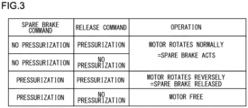
- FIG. 3 shows combinations of the spare brake command and the spare brake release command from the vehicle cab.
- the spare brake action switches 461 and 462 are closed, which makes the first path 44 conduct electricity, and the auxiliary switches 463 and 464 are opened, which does not make the second path 45 conduct electricity; therefore, regardless of whether or not the spare brake release command is given (pressurization or no pressurization), the DC motor 43 rotates normally, and the shoe 21 is driven to the brake action position.
- the spare brake acts regardless of whether or not the spare brake release command is given.
- the spare brake action switches 461 and 462 are not given the spare brake command and are open (pressurization), and the spare brake release switches 471 and 472 are not given the spare brake release command and are open (no pressurization).
- a brake which has conventionally needed to be manually released in the event of loss of a regular power supply, for example, can be easily released, with a simple configuration including the relay circuit 42 constituted by switches, the DC motor 43, and the like.
- the service brake unit 3 and the spare brake unit 4 are configured with different circuit boards and to house them in different casings.
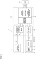
- FIG. 4 schematically illustrates a configuration of the braking device 1 according to a second embodiment. Constituting elements similar to those in the first embodiment, as shown in FIG. 1 and the like, will be denoted by the same reference characters, and repetitive description will be omitted.
- the braking device 1 includes the brake mechanism 2, the service brake unit 3, and a brake release device 6 as a spare brake unit.
- the power transmission mechanism 22 of the brake mechanism 2 is connected to the service brake unit 3 and the brake release device 6. When the service brake unit 3 is functioning, the power transmission mechanism 22 transmits the power of the service brake unit 3 to the shoe 21, and, when the service brake unit 3 is not functioning, the power transmission mechanism 22 transmits the power of the brake release device 6 to the shoe 21.
- the control of action and release of the brake is performed by the service brake unit 3.
- the control of release of the brake i.e., the driving of the shoe 21 from the brake action position to the brake release position, is performed by the brake release device 6.
- the brake release device 6 constitutes a spare brake unit that drives, when the service brake unit 3 is unable to drive the shoe 21 placed at the brake action position to the brake release position, the shoe 21 to the brake release position in response to a brake release command (shown as "OPERATION" in FIG. 4 ). More specifically, when the service brake unit 3 is not functioning, the brake release device 6 drives the shoe 21 from the brake action position to the brake release position, based on the DC electricity supplied from the battery 41.
- the brake release device 6 includes the battery 41, a switch 61 as an electricity supply controller, and the DC motor 43.
- the switch 61 supplies the DC electricity from the battery 41 to the DC motor 43, in response to a brake release command based on operation performed by a crew member, for example, in the vehicle cab or other places. More specifically, the switch 61 to which the brake release command is given is closed, which supplies the DC electricity from the battery 41 to the DC motor 43; on the other hand, the switch 61 to which the brake release command is not given is open, which does not supply the DC electricity from the battery 41 to the DC motor 43.
- the DC motor 43 drives the shoe 21 from the brake action position to the brake release position, based on a direct current in the second direction (or release direction or reverse rotation direction) supplied from the battery 41 via the switch 61.
- a brake which has conventionally needed to be manually released in the event of loss of a regular power supply, for example, can be easily released, with a simple configuration including the switch 61, the DC motor 43, and the like.
- the service brake unit 3 and the brake release device 6 In order to prevent abnormalities caused in the service brake unit 3 from affecting the brake release device 6 as a spare brake unit, it is preferable to configure the service brake unit 3 and the brake release device 6 with different circuit boards and to house them in different casings.
- a portion 10 enclosed by a dotted line constitutes an independent braking unit.
- the braking unit 10 includes the power transmission mechanism 22 of the brake mechanism 2, the control circuit 32 and the motor 33 of the service brake unit 3, and the entire brake release device 6.
- the braking device 1 shown in FIG. 4 can be configured.
- the braking unit 10 only includes the DC motor 43, instead of the entire brake release device 6.
- the battery 41 and the switch 61 as an electricity supply controller of the brake release device 6 are integrally provided as a power supply switch unit, which is attachable to and detachable from the braking unit 10 provided with the DC motor 43 as a spare electric motor.
- the remaining portion (power supply switch unit) of the brake release device 6 may be attached to the braking unit 10 only when the brake release device 6 needs to be used, i.e., when the service brake unit 3 is not functioning and the brake needs to be released by the brake release device 6.
- the entire brake release device 6 as a spare brake unit may be made attachable to and detachable from the braking unit 10.
- each device described in the embodiments can be implemented by hardware resources, software resources, or cooperation between hardware resources and software resources.
- hardware resources processors, ROMs, RAMs, or other LSIs can be employed.
- software resources programs, such as operating system programs and application programs, can be employed.
Landscapes
- Engineering & Computer Science (AREA)
- Transportation (AREA)
- Mechanical Engineering (AREA)
- Braking Systems And Boosters (AREA)
- Braking Arrangements (AREA)
- Valves And Accessory Devices For Braking Systems (AREA)
Abstract
Description
- The present invention relates to a braking technology for railroad vehicles.
-
Patent Literature 1 discloses an electric brake actuator including a service brake mechanism unit that uses rotational power of a motor to drive a push rod equipped with a friction material that is pressed against a wheel of a railroad vehicle, and a spare brake mechanism unit that uses spring force to move the push rod. InPatent Literature 1, when the service brake mechanism unit cannot operate due to a power failure or the like, the spare brake mechanism unit activates the spare brake by means of the push rod that is moved by the force of a pressurized spring, so as to safely stop the railroad vehicle. Then, after recovery from the power failure, the service brake mechanism unit is operated such as to generate the maximum brake force, and the spring is pressurized again by means of the reaction force. - Patent Literature 1:
Japanese Translation of PCT International Application Publication No. 2001-521468 - In the technology described in
Patent Literature 1, when the service brake mechanism unit cannot be operated, the spare brake activated by the spring cannot be released. Accordingly, a worker who goes to the site needs to manually return the push rod in the direction of pressurizing the spring, for example, to release the spare brake. - The present invention has been made in view of such a situation, and a purpose thereof is to provide a braking device and the like that can reduce the workload related to the operation of a spare brake when a service brake cannot be used.
- In response to the above issue, a braking device according to one aspect of the present invention includes: a brake mechanism that presses a friction material against a braking target member of a railroad vehicle to brake the railroad vehicle; a spare electric motor that drives the brake mechanism and that is different from a regular electric motor; a spare power supply that supplies electricity to the spare electric motor and that is different from a regular power supply; and an electricity supply controller that controls supply of electricity from the spare power supply to the spare electric motor in response to a spare brake command.
- According to this aspect, even when the regular electric motor and/or the regular power supply cannot be used, the spare brake can be operated with the spare electric motor and the spare power supply.
- Another aspect of the present invention relates to a spare brake control device. The spare brake control device includes: a spare power supply that is different from a regular power supply; a spare electric motor that drives a friction material, which is pressed against a braking target member of a railroad vehicle to brake the railroad vehicle, based on electricity supplied from the spare power supply and that is different from a regular electric motor; and an electricity supply controller that controls supply of electricity from the spare power supply to the spare electric motor in response to a spare brake command.
- Optional combinations of the aforementioned constituting elements, and implementation of the present invention in the form of methods, apparatuses, systems, recording media, and computer programs may also be practiced as additional modes of the present invention.
- The present invention reduces the workload related to the operation of a spare brake when a service brake cannot be used.
- Embodiments will now be described, by way of example only, with reference to the accompanying drawings which are meant to be exemplary, not limiting, and wherein like elements are numbered alike in several Figures, in which:
-
FIG. 1 schematically illustrates a configuration of a braking device according to a first embodiment; -
FIG. 2 schematically illustrates the details of a relay circuit; -
FIG. 3 shows combinations of a spare brake action command and a spare brake release command from a vehicle cab; -
FIG. 4 schematically illustrates a configuration of the braking device according to a second embodiment; -
FIG. 5 schematically illustrates a configuration of the braking device according to a third embodiment; and -
FIG. 6 schematically illustrates a configuration of the braking device according to a fourth embodiment. -
FIG. 1 schematically illustrates a configuration of abraking device 1 according to a first embodiment. Thebraking device 1 includes abrake mechanism 2, aservice brake unit 3, and aspare brake unit 4 as a spare brake control device. The spare brake is sometimes referred to as a security brake, a backup brake, or an emergency brake. Theservice brake unit 3 and thespare brake unit 4 are controlled by commands from a brake command unit or acontrol unit 5. - The
brake mechanism 2, which constitutes a tread brake, includes ashoe 21 as a friction material that is pressed against a wheel, which is a braking target member in a railroad vehicle, to brake the railroad vehicle. Theshoe 21 faces at least part of the outer circumference of the wheel, and, on the facing surface (inner circumference surface), brake lining or the like is provided. As will be described later, theshoe 21 is driven in a radial direction of the wheel by theservice brake unit 3 or thespare brake unit 4 and, when theshoe 21 reaches a brake action position where it comes into contact with the wheel and is then pressed, the frictional force between the brake lining or the like and the wheel slows the rotation of the wheel to brake the railroad vehicle. - The
brake mechanism 2 may also be configured as a disc brake, and pads may be provided as the friction material instead of theshoe 21 used in a tread brake. The pads sandwich a brake disc, which rotates integrally with a wheel, from both sides in a rotational axis direction, and, on the surface of each pad that faces the brake disc, brake lining or the like is provided. The pads are driven in the rotational axis directions of the wheel by theservice brake unit 3 or thespare brake unit 4 and, when the pads reach the brake action position where the pads come into contact with the brake disc from both sides and are then pressed, the frictional force between the brake lining or the like and the brake disc slows the rotation of the wheel to brake the railroad vehicle. Thebrake mechanism 2 may also be configured as any other arbitrary type of brake, such as a drum brake. - The
brake mechanism 2 further includes apower transmission mechanism 22 connected to theservice brake unit 3 and thespare brake unit 4. When theservice brake unit 3 is functioning, thepower transmission mechanism 22 transmits the power of theservice brake unit 3 to theshoe 21, and, when theservice brake unit 3 is not functioning, thepower transmission mechanism 22 transmits the power of thespare brake unit 4 to theshoe 21. Thus, thepower transmission mechanism 22 preferentially transmits the power of theservice brake unit 3 to theshoe 21 and transmits, only when theservice brake unit 3 is not functioning, the power of thespare brake unit 4 to theshoe 21. Thepower transmission mechanism 22 may be configured by a combination of publicly-known mechanical elements, such as a clutch and Torque Diode (trademark). Thepower transmission mechanism 22 may be equipped with a booster mechanism, such as a toggle mechanism, that amplifies rotational power generated by the motors of theservice brake unit 3 and thespare brake unit 4, and a reduction mechanism that obtains torque corresponding to the reduction ratio of the rotational power. Thepower transmission mechanism 22 also includes a rotational-linear transformation mechanism that transforms the rotational power generated by the motors of theservice brake unit 3 and thespare brake unit 4 into linear power used to drive theshoe 21 in the radial direction. - The
service brake unit 3 includes avehicle power supply 31 as a regular power supply, acontrol circuit 32, and amotor 33 as a regular electric motor. Thevehicle power supply 31 may be provided outside theservice brake unit 3 or even outside thebraking device 1. Thevehicle power supply 31 may supply thecontrol circuit 32 with electricity supplied from a pantograph to the railroad vehicle. Thevehicle power supply 31 mounted on at least one railroad vehicle supplies alternating-current (AC) or direct-current (DC) electricity supplied through a train line, such as an overhead train line (overhead line) and a power feed rail (third rail), to various equipment and devices of the railroad vehicle, including thecontrol circuit 32 and themotor 33. Thecontrol circuit 32 includes an inverter for generating multiphase AC electricity of desired frequency and amplitude based on the electricity supplied from thevehicle power supply 31, so as to generate AC electricity, such as three-phase AC electricity, to be applied to themotor 33 in response to a service brake command from the vehicle cab as thecontrol unit 5. Themotor 33 as the regular electric motor is an AC motor, which drives theshoe 21 based on the AC electricity generated by thecontrol circuit 32 in response to a service brake command from thecontrol unit 5. - The service brake commands from the vehicle cab as the
control unit 5 are broadly classified into a service brake action command issued to drive theshoe 21 to the brake action position where theshoe 21 is pressed against the wheel, and a service brake release command issued to drive theshoe 21 to a brake release position where theshoe 21 is not pressed against the wheel. When the service brake action command is given by thecontrol unit 5, thecontrol circuit 32 rotates the rotor of themotor 33 in a first direction (hereinafter, also referred to as an action direction or a normal rotation direction) to generate a first alternating current (hereinafter, also referred to as an action alternating current or a normal rotation alternating current) to drive theshoe 21 to the brake action position. Also, when the service brake release command is given by thecontrol unit 5, thecontrol circuit 32 rotates the rotor of themotor 33 in a second direction (hereinafter, also referred to as a release direction or a reverse rotation direction), which is opposite to the first direction, to generate a second alternating current (hereinafter, also referred to as a release alternating current or a reverse rotation alternating current) to drive theshoe 21 to the brake release position. - When the
service brake unit 3 is functioning properly, i.e., when all of thevehicle power supply 31, thecontrol circuit 32, and themotor 33 are functioning properly, the control of action and release of the brake, i.e., driving of theshoe 21 between the brake action position and the brake release position, is performed by theservice brake unit 3. On the other hand, when theservice brake unit 3 is not functioning properly, i.e., when at least one of thevehicle power supply 31, thecontrol circuit 32, or themotor 33 is not functioning properly, the control of action and release of the brake, i.e., driving of theshoe 21 between the brake action position and the brake release position, is performed by thespare brake unit 4. - The
spare brake unit 4 constitutes a spare brake drive device that drives, when theservice brake unit 3 is unable to drive theshoe 21 placed at the brake action position to the brake release position, theshoe 21 to the brake release position in response to a spare brake release command (shown as "RELEASE COMMAND" inFIG. 1 ) from thecontrol unit 5. More specifically, when theservice brake unit 3 is not functioning, thespare brake unit 4 drives theshoe 21 between the brake action position and the brake release position, based on DC electricity supplied from abattery 41 as a spare power supply. Thespare brake unit 4 includes thebattery 41, arelay circuit 42 as an electricity supply controller, and aDC motor 43 as a spare electric motor and a DC electric motor. - The
battery 41, different from thevehicle power supply 31, supplies DC electricity. Therelay circuit 42 supplies the DC electricity from thebattery 41 to theDC motor 43, in response to a spare brake command as a spare brake action command and a spare brake release command from thecontrol unit 5. TheDC motor 43 drives theshoe 21 between the brake action position and the brake release position, based on the DC electricity supplied from thebattery 41 via therelay circuit 42. TheDC motor 43 may be constituted by an inverter that converts the DC electricity supplied from therelay circuit 42 into AC electricity, and by an electric motor, similar to the regular electric motor (motor 33), that generates rotational power based on the AC electricity converted by the inverter. -
FIG. 2 schematically illustrates the details of therelay circuit 42. In therelay circuit 42, afirst path 44 and asecond path 45, which each connect thebattery 41 and theDC motor 43, are provided in parallel. Thefirst path 44 includes a highpotential line 441 connected to a highpotential terminal 411 of thebattery 41, and a lowpotential line 442 connected to a lowpotential terminal 412 of thebattery 41. The highpotential line 441 is also connected to afirst terminal 431 of theDC motor 43 via a sparebrake action switch 461, which will be described later, and the lowpotential line 442 is also connected to asecond terminal 432 of theDC motor 43 via a sparebrake action switch 462, which will also be described later. - The
second path 45, which connects thebattery 41 and theDC motor 43 in parallel with thefirst path 44, includes a firstparallel line 451 that is connected to the highpotential line 441 on thebattery 41 side with respect to the sparebrake action switch 461, anauxiliary switch 463, and a sparebrake release switch 471, which will be described later, and that is also connected to thesecond terminal 432 of theDC motor 43 with respect to the sparebrake action switch 461, theauxiliary switch 463, and the sparebrake release switch 471. Thesecond path 45 also includes a secondparallel line 452 that is connected to the lowpotential line 442 on thebattery 41 side with respect to the sparebrake action switch 462, anauxiliary switch 464, and a sparebrake release switch 472, which will be described later, and that is also connected to thefirst terminal 431 of theDC motor 43 with respect to the sparebrake action switch 462, theauxiliary switch 464, and the sparebrake release switch 472. Thus, the firstparallel line 451 and the secondparallel line 452 are connected to the highpotential line 441 and the lowpotential line 442 such as to cross each other. - Each of the
first path 44 and thesecond path 45 conducts electricity and hence supplies DC electricity to theDC motor 43 when all the switches provided on the path are closed. As will be described later, thefirst path 44 and thesecond path 45 do not conduct electricity simultaneously. More specifically, when the spare brake action switches 461 and 462 are closed, thefirst path 44 conducts electricity, so that the highpotential terminal 411 of thebattery 41 is connected to thefirst terminal 431 of theDC motor 43 via the highpotential line 441, and the lowpotential terminal 412 of thebattery 41 is connected to thesecond terminal 432 of theDC motor 43 via the lowpotential line 442. At the time, in theDC motor 43, a direct current flows in the first direction from thefirst terminal 431 of high potential toward thesecond terminal 432 of low potential, and the rotor of theDC motor 43 rotates in the first direction (or action direction or normal rotation direction), so that theshoe 21 is driven to the brake action position. - Meanwhile, when the
auxiliary switches second path 45 conducts electricity, so that the highpotential terminal 411 of thebattery 41 is connected to thesecond terminal 432 of theDC motor 43 via the firstparallel line 451, and the lowpotential terminal 412 of thebattery 41 is connected to thefirst terminal 431 of theDC motor 43 via the secondparallel line 452. At the time, in theDC motor 43, a direct current flows in the second direction (opposite to the first direction) from thesecond terminal 432 of high potential toward thefirst terminal 431 of low potential, and the rotor of theDC motor 43 rotates in the second direction (or release direction or reverse rotation direction), so that theshoe 21 is driven to the brake release position. - A
spare relay 46, which is controlled by a spare brake command as a spare brake action command from the vehicle cab as thecontrol unit 5, includes the sparebrake action switch 461 provided on the highpotential line 441, the sparebrake action switch 462 provided on the lowpotential line 442, theauxiliary switch 463 provided on the firstparallel line 451, and theauxiliary switch 464 provided on the secondparallel line 452. These four switches 461-464 are mechanically connected and are biased upward inFIG. 2 by springs or the like. When the spare brake command is given by the vehicle cab, the switches 461-464 are not pressurized downward, so that, by the upward biasing force, the spare brake action switches 461 and 462 are closed, and theauxiliary switches auxiliary switches auxiliary switches - Accordingly, while the
first path 44 conducts electricity, since the spare brake action switches 461 and 462 are closed whereas theauxiliary switches second path 45 cannot conduct electricity. Similarly, while thesecond path 45 conducts electricity, since theauxiliary switches first path 44 cannot conduct electricity. Therefore, thefirst path 44 and thesecond path 45 do not conduct electricity simultaneously, thereby effectively preventing the conflict between the action of the spare brake implemented by the conduction of thefirst path 44 and the release of the spare brake implemented by the conduction of thesecond path 45. - A
release relay 47, which is controlled by a spare brake release command (shown as "RELEASE COMMAND" inFIG. 2 ) from the vehicle cab as thecontrol unit 5, includes the sparebrake release switch 471 provided in series with theauxiliary switch 463 on the firstparallel line 451, and the sparebrake release switch 472 provided in series with theauxiliary switch 464 on the secondparallel line 452. These twoswitches FIG. 2 by springs or the like. When the spare brake release command is given by the vehicle cab, theswitches switches -
FIG. 3 shows combinations of the spare brake command and the spare brake release command from the vehicle cab. In the case of "no pressurization" in which the spare brake command is given by the vehicle cab, the spare brake action switches 461 and 462 are closed, which makes thefirst path 44 conduct electricity, and theauxiliary switches second path 45 conduct electricity; therefore, regardless of whether or not the spare brake release command is given (pressurization or no pressurization), theDC motor 43 rotates normally, and theshoe 21 is driven to the brake action position. In short, when the spare brake command is given from the vehicle cab, the spare brake acts regardless of whether or not the spare brake release command is given. - In the case of "pressurization" in which the spare brake command is not given by the vehicle cab and, in addition, in the case of "pressurization" in which the spare brake release command is given by the vehicle cab, the
auxiliary switches second path 45 conduct electricity, and the spare brake action switches 461 and 462 are opened, which does not make thefirst path 44 conduct electricity; therefore, theDC motor 43 rotates reversely, and theshoe 21 is driven to the brake release position. In this way, when the spare brake release switches 471 and 472 are closed in response to the spare brake release command "pressurization" and also in the case of "pressurization" in which the spare brake command is not given to the spare brake action switches 461 and 462, a direct current in the second direction (or release direction or reverse rotation direction) is applied to theDC motor 43 to drive theshoe 21 to the brake release position. - In the case of "pressurization" in which the spare brake command is not given by the vehicle cab and, in addition, in the case of "no pressurization" in which the spare brake release command is not given by the vehicle cab, the spare brake action switches 461 and 462 are opened, which does not make the
first path 44 conduct electricity, and the spare brake release switches 471 and 472 are opened, which does not make thesecond path 45 conduct electricity; therefore, the state is placed in a "motor free" state in which the DC electricity from thebattery 41 is not supplied to theDC motor 43. This combination of the spare brake command "pressurization" and the spare brake release command "no pressurization" is set when theservice brake unit 3 is functioning properly and there is no need to use thespare brake unit 4. Thus, when theservice brake unit 3 is functioning, the spare brake action switches 461 and 462 are not given the spare brake command and are open (pressurization), and the spare brake release switches 471 and 472 are not given the spare brake release command and are open (no pressurization). - According to the first embodiment described above, a brake, which has conventionally needed to be manually released in the event of loss of a regular power supply, for example, can be easily released, with a simple configuration including the
relay circuit 42 constituted by switches, theDC motor 43, and the like. In order to prevent abnormalities caused in theservice brake unit 3 from affecting thespare brake unit 4, it is preferable to configure theservice brake unit 3 and thespare brake unit 4 with different circuit boards and to house them in different casings. -
FIG. 4 schematically illustrates a configuration of thebraking device 1 according to a second embodiment. Constituting elements similar to those in the first embodiment, as shown inFIG. 1 and the like, will be denoted by the same reference characters, and repetitive description will be omitted. Thebraking device 1 includes thebrake mechanism 2, theservice brake unit 3, and abrake release device 6 as a spare brake unit. - The
power transmission mechanism 22 of thebrake mechanism 2 is connected to theservice brake unit 3 and thebrake release device 6. When theservice brake unit 3 is functioning, thepower transmission mechanism 22 transmits the power of theservice brake unit 3 to theshoe 21, and, when theservice brake unit 3 is not functioning, thepower transmission mechanism 22 transmits the power of thebrake release device 6 to theshoe 21. - When the
service brake unit 3 is functioning properly, the control of action and release of the brake is performed by theservice brake unit 3. When theservice brake unit 3 is not functioning properly, on the other hand, the control of release of the brake, i.e., the driving of theshoe 21 from the brake action position to the brake release position, is performed by thebrake release device 6. - The
brake release device 6 constitutes a spare brake unit that drives, when theservice brake unit 3 is unable to drive theshoe 21 placed at the brake action position to the brake release position, theshoe 21 to the brake release position in response to a brake release command (shown as "OPERATION" inFIG. 4 ). More specifically, when theservice brake unit 3 is not functioning, thebrake release device 6 drives theshoe 21 from the brake action position to the brake release position, based on the DC electricity supplied from thebattery 41. Thebrake release device 6 includes thebattery 41, aswitch 61 as an electricity supply controller, and theDC motor 43. - The
switch 61 supplies the DC electricity from thebattery 41 to theDC motor 43, in response to a brake release command based on operation performed by a crew member, for example, in the vehicle cab or other places. More specifically, theswitch 61 to which the brake release command is given is closed, which supplies the DC electricity from thebattery 41 to theDC motor 43; on the other hand, theswitch 61 to which the brake release command is not given is open, which does not supply the DC electricity from thebattery 41 to theDC motor 43. TheDC motor 43 drives theshoe 21 from the brake action position to the brake release position, based on a direct current in the second direction (or release direction or reverse rotation direction) supplied from thebattery 41 via theswitch 61. - According to the second embodiment described above, a brake, which has conventionally needed to be manually released in the event of loss of a regular power supply, for example, can be easily released, with a simple configuration including the
switch 61, theDC motor 43, and the like. In order to prevent abnormalities caused in theservice brake unit 3 from affecting thebrake release device 6 as a spare brake unit, it is preferable to configure theservice brake unit 3 and thebrake release device 6 with different circuit boards and to house them in different casings. - In the second embodiment described above, a
portion 10 enclosed by a dotted line constitutes an independent braking unit. More specifically, thebraking unit 10 includes thepower transmission mechanism 22 of thebrake mechanism 2, thecontrol circuit 32 and themotor 33 of theservice brake unit 3, and the entirebrake release device 6. By attaching theshoe 21 and thevehicle power supply 31 to thebraking unit 10, thebraking device 1 shown inFIG. 4 can be configured. - In a third embodiment shown in
FIG. 5 , thebraking unit 10 only includes theDC motor 43, instead of the entirebrake release device 6. Thebattery 41 and theswitch 61 as an electricity supply controller of thebrake release device 6 are integrally provided as a power supply switch unit, which is attachable to and detachable from thebraking unit 10 provided with theDC motor 43 as a spare electric motor. Thus, by making at least part of thebrake release device 6 as a spare brake unit attachable to and detachable from thebraking unit 10, the remaining portion (power supply switch unit) of thebrake release device 6 may be attached to thebraking unit 10 only when thebrake release device 6 needs to be used, i.e., when theservice brake unit 3 is not functioning and the brake needs to be released by thebrake release device 6. By configuring the power supply switch unit separately from thebraking unit 10, a single power supply switch unit can be shared among multiple brakingunits 10. As in a fourth embodiment shown inFIG. 6 , the entirebrake release device 6 as a spare brake unit may be made attachable to and detachable from thebraking unit 10. - The present invention has been described with reference to embodiments. The embodiments are intended to be illustrative only, and it will be obvious to those skilled in the art that various modifications to a combination of constituting elements or processes could be developed and that such modifications also fall within the scope of the present invention.
- The functional configuration of each device described in the embodiments can be implemented by hardware resources, software resources, or cooperation between hardware resources and software resources. As the hardware resources, processors, ROMs, RAMs, or other LSIs can be employed. As the software resources, programs, such as operating system programs and application programs, can be employed.
- In the embodiments disclosed in the present specification, when multiple functions are provided in a distributed manner, some or all of the multiple functions may be collectively provided, and, conversely, when multiple functions are collectively provided, some or all of the multiple functions may be provided in a distributed manner. Regardless of whether the functions are aggregated or distributed, configurations have only to be made such that a purpose of the invention can be achieved.
- 1
- braking device
- 2
- brake mechanism
- 3
- service brake unit
- 4
- spare brake unit
- 5
- control unit
- 6
- brake release device
- 10
- braking unit
- 21
- shoe
- 22
- power transmission mechanism
- 31
- vehicle power supply
- 32
- control circuit
- 33
- motor
- 41
- battery
- 42
- relay circuit
- 43
- DC motor
- 44
- first path
- 45
- second path
- 46
- spare relay
- 47
- release relay
- 61
- switch
- 411
- high potential terminal
- 412
- low potential terminal
- 431
- first terminal
- 432
- second terminal
- 441
- high potential line
- 442
- low potential line
- 451
- first parallel line
- 452
- second parallel line
- 461
- spare brake action switch
- 462
- spare brake action switch
- 463
- auxiliary switch
- 464
- auxiliary switch
- 471
- spare brake release switch
- 472
- spare brake release switch
Claims (11)
- A braking device (1), comprising:a brake mechanism (2) that presses a friction material against a braking target member of a railroad vehicle to brake the railroad vehicle;a spare electric motor that drives the brake mechanism (2) and that is different from a regular electric motor;a spare power supply that supplies electricity to the spare electric motor and that is different from a regular power supply; andan electricity supply controller that controls supply of electricity from the spare power supply to the spare electric motor in response to a spare brake command.
- The braking device (1) according to claim 1, whereinthe spare power supply is a direct-current (DC) power supply that supplies DC electricity,the spare electric motor is a DC electric motor that drives the brake mechanism (2) based on the DC electricity, andthe electricity supply controller is a relay circuit (42) that switches a path between the DC power supply and the DC electric motor in response to the spare brake command.
- The braking device (1) according to claim 2, wherein the relay circuit (42) comprises:a brake action switch that is provided on a first path (44) connecting the DC power supply and the DC electric motor and that is closed in response to the spare brake command, thereby applying a direct current in a first direction to the DC electric motor and pressing the friction material against the braking target member; anda brake release switch that is provided on a second path (45) connecting the DC power supply and the DC electric motor in parallel with the first path (44) and that is closed in response to a brake release command, thereby applying, when the spare brake command is not given to the brake action switch, a direct current in a second direction, opposite to the first direction, to the DC electric motor and driving the friction material to a brake release position.
- The braking device (1) according to claim 3, wherein, when the regular electric motor and the regular power supply are functioning, the brake action switch is not given the spare brake command and is open, and the brake release switch is not given the brake release command and is open.
- The braking device (1) according to claim 3 or 4, wherein the relay circuit (42) comprises an auxiliary switch (463, 464) that is provided in series with the brake release switch on the second path and that is opened in response to the spare brake command.
- The braking device (1) according to any one of claims 3 through 5, whereinthe first path (44) comprises a high potential line (441) connected to a high potential terminal (411) of the DC power supply, and a low potential line (442) connected to a low potential terminal (412) of the DC power supply, andthe second path (45) comprises a first parallel line (451) that is connected to the high potential line (441) on the DC power supply side with respect to the brake action switch and the brake release switch and that is also connected to the low potential line (442) on the DC electric motor side with respect to the brake action switch and the brake release switch, and a second parallel line (452) that is connected to the low potential line (442) on the DC power supply side with respect to the brake action switch and the brake release switch and that is also connected to the high potential line (441) on the DC electric motor side with respect to the brake action switch and the brake release switch.
- The braking device (1) according to any one of claims 1 through 6, wherein at least one of the spare electric motor, the spare power supply, or the electricity supply controller is attachable to and detachable from the braking device (1).
- The braking device (1) according to claim 7, wherein the spare power supply and the electricity supply controller are attachable to and detachable from the braking device (1) provided with the spare electric motor.
- The braking device (1) according to any one of claims 1 through 8, whereinthe regular electric motor drives the friction material based on alternating-current (AC) electricity,the braking device (1) further comprising an inverter that generates AC electricity to be applied to the regular electric motor based on electricity supplied from the regular power supply.
- The braking device (1) according to claim 9, wherein the inverter and the electricity supply controller are configured with different circuit boards.
- The braking device (1) according to claim 9 or 10, wherein the inverter and the electricity supply controller are housed in different casings.
Applications Claiming Priority (1)
| Application Number | Priority Date | Filing Date | Title |
|---|---|---|---|
| JP2022024072A JP7837744B2 (en) | 2022-02-18 | 2022-02-18 | Braking system, auxiliary brake control device |
Publications (2)
| Publication Number | Publication Date |
|---|---|
| EP4230487A1 true EP4230487A1 (en) | 2023-08-23 |
| EP4230487B1 EP4230487B1 (en) | 2024-11-20 |
Family
ID=85150413
Family Applications (1)
| Application Number | Title | Priority Date | Filing Date |
|---|---|---|---|
| EP23153901.6A Active EP4230487B1 (en) | 2022-02-18 | 2023-01-30 | Braking device and spare brake control device |
Country Status (4)
| Country | Link |
|---|---|
| EP (1) | EP4230487B1 (en) |
| JP (1) | JP7837744B2 (en) |
| CN (1) | CN116620232B (en) |
| TW (1) | TWI863131B (en) |
Cited By (1)
| Publication number | Priority date | Publication date | Assignee | Title |
|---|---|---|---|---|
| EP4624289A1 (en) * | 2024-03-28 | 2025-10-01 | Nabtesco Corporation | Unit brake device |
Citations (6)
| Publication number | Priority date | Publication date | Assignee | Title |
|---|---|---|---|---|
| DE68902940T2 (en) * | 1988-03-21 | 1993-01-07 | Wabco Holdings Sab | AN ACTUATOR. |
| DE19611910A1 (en) * | 1996-03-26 | 1997-10-02 | Bosch Gmbh Robert | Electromechanical braking device |
| US6012556A (en) * | 1996-12-30 | 2000-01-11 | Robert Bosch Gmbh | Electric motor-driven braking apparatus |
| US6138801A (en) * | 1997-11-14 | 2000-10-31 | Toyota Jidosha Kabushiki Kaisha | Electrically operated brake including two electric motors connected to planetary gear device, and braking system including such brake or brakes |
| JP2001521468A (en) | 1997-04-24 | 2001-11-06 | サーブ ワブコ アーベー | Electric assisted brake actuator |
| US20130270047A1 (en) * | 2012-04-17 | 2013-10-17 | Jin Seok Kim | Electric parking brake |
Family Cites Families (13)
| Publication number | Priority date | Publication date | Assignee | Title |
|---|---|---|---|---|
| JP2000261982A (en) * | 1999-03-10 | 2000-09-22 | Toyota Motor Corp | Vehicle power supply control device |
| JP4330340B2 (en) * | 2000-12-19 | 2009-09-16 | クノル−ブレムゼ ジステーメ フューア シーネンファールツォイゲ ゲゼルシャフト ミット ベシュレンクテル ハフツング | Electromechanical brake crimping device |
| JP5372086B2 (en) * | 2011-08-31 | 2013-12-18 | 本田技研工業株式会社 | Vehicle control device |
| WO2016047481A1 (en) * | 2014-09-25 | 2016-03-31 | Ntn株式会社 | Electric brake system |
| JP5839634B1 (en) * | 2015-01-16 | 2016-01-06 | ニチユ三菱フォークリフト株式会社 | Vehicle control apparatus, vehicle control circuit, vehicle, vehicle control method, and program |
| JP6054463B2 (en) * | 2015-05-07 | 2016-12-27 | Ntn株式会社 | Electric brake system |
| JP6372676B2 (en) * | 2015-12-25 | 2018-08-15 | パナソニックIpマネジメント株式会社 | Brake boost system and intake device used therefor |
| JP6729253B2 (en) * | 2016-09-30 | 2020-07-22 | 株式会社オートネットワーク技術研究所 | Backup device for vehicle |
| JP6624097B2 (en) * | 2017-02-01 | 2019-12-25 | トヨタ自動車株式会社 | Vehicle brake system |
| WO2018181807A1 (en) * | 2017-03-31 | 2018-10-04 | 日信工業株式会社 | Vehicular brake system |
| CN110505972B (en) * | 2017-03-31 | 2023-02-28 | 本田技研工业株式会社 | vehicle |
| FR3074733A1 (en) * | 2017-12-13 | 2019-06-14 | Lohr Electromecanique | ELECTRIC DIRECTIONAL AXLE FOR VEHICLE |
| JP7308047B2 (en) * | 2019-02-12 | 2023-07-13 | ナブテスコ株式会社 | Brake equipment for railway vehicles |
-
2022
- 2022-02-18 JP JP2022024072A patent/JP7837744B2/en active Active
-
2023
- 2023-01-30 EP EP23153901.6A patent/EP4230487B1/en active Active
- 2023-02-14 TW TW112105106A patent/TWI863131B/en active
- 2023-02-17 CN CN202310130701.6A patent/CN116620232B/en active Active
Patent Citations (6)
| Publication number | Priority date | Publication date | Assignee | Title |
|---|---|---|---|---|
| DE68902940T2 (en) * | 1988-03-21 | 1993-01-07 | Wabco Holdings Sab | AN ACTUATOR. |
| DE19611910A1 (en) * | 1996-03-26 | 1997-10-02 | Bosch Gmbh Robert | Electromechanical braking device |
| US6012556A (en) * | 1996-12-30 | 2000-01-11 | Robert Bosch Gmbh | Electric motor-driven braking apparatus |
| JP2001521468A (en) | 1997-04-24 | 2001-11-06 | サーブ ワブコ アーベー | Electric assisted brake actuator |
| US6138801A (en) * | 1997-11-14 | 2000-10-31 | Toyota Jidosha Kabushiki Kaisha | Electrically operated brake including two electric motors connected to planetary gear device, and braking system including such brake or brakes |
| US20130270047A1 (en) * | 2012-04-17 | 2013-10-17 | Jin Seok Kim | Electric parking brake |
Cited By (1)
| Publication number | Priority date | Publication date | Assignee | Title |
|---|---|---|---|---|
| EP4624289A1 (en) * | 2024-03-28 | 2025-10-01 | Nabtesco Corporation | Unit brake device |
Also Published As
| Publication number | Publication date |
|---|---|
| TW202346126A (en) | 2023-12-01 |
| JP7837744B2 (en) | 2026-03-31 |
| TWI863131B (en) | 2024-11-21 |
| CN116620232A (en) | 2023-08-22 |
| EP4230487B1 (en) | 2024-11-20 |
| JP2023120925A (en) | 2023-08-30 |
| CN116620232B (en) | 2026-02-13 |
Similar Documents
| Publication | Publication Date | Title |
|---|---|---|
| US5226508A (en) | Disc brake for elevator drive sheave | |
| KR101817520B1 (en) | Electronic Parking Brake system | |
| US8302739B2 (en) | Brake device for a lift car | |
| EP2284054A1 (en) | Decentralized electric brake system | |
| WO2017002452A1 (en) | Electromechanical brake device | |
| EP4230487B1 (en) | Braking device and spare brake control device | |
| EP4110662B1 (en) | Safety release in electric brake system | |
| JP2000344449A5 (en) | ||
| US7344207B2 (en) | Apparatus for preventing untimely braking in a brake having electromechanical actuators | |
| WO2018216111A1 (en) | Brake release device for elevator | |
| US10384546B2 (en) | System and method for controlling a vehicle | |
| CN113748076A (en) | Drive device for an elevator installation | |
| JP2023533788A (en) | Electromechanical brake actuator and brake system for vehicles, in particular for at least one railway vehicle | |
| EP4032763B1 (en) | A brake system for braking a vehicle | |
| KR102423381B1 (en) | Input power means and the control method of electromechanical braking system for railway vehicles | |
| KR101614896B1 (en) | Electronic motorized modular brake system | |
| EP4360972A1 (en) | Brake unit for a rail vehicle | |
| JP2018524219A (en) | Brake device and method | |
| JP7793112B2 (en) | Brake control device, mechanical brake device, and brake control system | |
| KR102251095B1 (en) | Wedge Brake | |
| JP7785245B2 (en) | Brake control device, mechanical brake device, and brake control system | |
| KR102400250B1 (en) | EMB multi control system and method for railway vehicles | |
| KR20010000492U (en) | Crane emergency brake | |
| JPH10167638A (en) | Door braking device | |
| CA2407289A1 (en) | Process for driving a workpiece transport system for a press arrangement |
Legal Events
| Date | Code | Title | Description |
|---|---|---|---|
| PUAI | Public reference made under article 153(3) epc to a published international application that has entered the european phase |
Free format text: ORIGINAL CODE: 0009012 |
|
| STAA | Information on the status of an ep patent application or granted ep patent |
Free format text: STATUS: REQUEST FOR EXAMINATION WAS MADE |
|
| 17P | Request for examination filed |
Effective date: 20230130 |
|
| AK | Designated contracting states |
Kind code of ref document: A1 Designated state(s): AL AT BE BG CH CY CZ DE DK EE ES FI FR GB GR HR HU IE IS IT LI LT LU LV MC ME MK MT NL NO PL PT RO RS SE SI SK SM TR |
|
| P01 | Opt-out of the competence of the unified patent court (upc) registered |
Effective date: 20231116 |
|
| RBV | Designated contracting states (corrected) |
Designated state(s): AL AT BE BG CH CY CZ DE DK EE ES FI FR GB GR HR HU IE IS IT LI LT LU LV MC ME MK MT NL NO PL PT RO RS SE SI SK SM TR |
|
| GRAP | Despatch of communication of intention to grant a patent |
Free format text: ORIGINAL CODE: EPIDOSNIGR1 |
|
| GRAP | Despatch of communication of intention to grant a patent |
Free format text: ORIGINAL CODE: EPIDOSNIGR1 |
|
| STAA | Information on the status of an ep patent application or granted ep patent |
Free format text: STATUS: GRANT OF PATENT IS INTENDED |
|
| INTG | Intention to grant announced |
Effective date: 20240614 |
|
| GRAS | Grant fee paid |
Free format text: ORIGINAL CODE: EPIDOSNIGR3 |
|
| GRAA | (expected) grant |
Free format text: ORIGINAL CODE: 0009210 |
|
| STAA | Information on the status of an ep patent application or granted ep patent |
Free format text: STATUS: THE PATENT HAS BEEN GRANTED |
|
| AK | Designated contracting states |
Kind code of ref document: B1 Designated state(s): AL AT BE BG CH CY CZ DE DK EE ES FI FR GB GR HR HU IE IS IT LI LT LU LV MC ME MK MT NL NO PL PT RO RS SE SI SK SM TR |
|
| REG | Reference to a national code |
Ref country code: GB Ref legal event code: FG4D |
|
| REG | Reference to a national code |
Ref country code: CH Ref legal event code: EP |
|
| REG | Reference to a national code |
Ref country code: DE Ref legal event code: R096 Ref document number: 602023001033 Country of ref document: DE |
|
| REG | Reference to a national code |
Ref country code: IE Ref legal event code: FG4D |
|
| REG | Reference to a national code |
Ref country code: LT Ref legal event code: MG9D |
|
| REG | Reference to a national code |
Ref country code: NL Ref legal event code: MP Effective date: 20241120 |
|
| PG25 | Lapsed in a contracting state [announced via postgrant information from national office to epo] |
Ref country code: IS Free format text: LAPSE BECAUSE OF FAILURE TO SUBMIT A TRANSLATION OF THE DESCRIPTION OR TO PAY THE FEE WITHIN THE PRESCRIBED TIME-LIMIT Effective date: 20250320 Ref country code: PT Free format text: LAPSE BECAUSE OF FAILURE TO SUBMIT A TRANSLATION OF THE DESCRIPTION OR TO PAY THE FEE WITHIN THE PRESCRIBED TIME-LIMIT Effective date: 20250320 Ref country code: HR Free format text: LAPSE BECAUSE OF FAILURE TO SUBMIT A TRANSLATION OF THE DESCRIPTION OR TO PAY THE FEE WITHIN THE PRESCRIBED TIME-LIMIT Effective date: 20241120 |
|
| PG25 | Lapsed in a contracting state [announced via postgrant information from national office to epo] |
Ref country code: FI Free format text: LAPSE BECAUSE OF FAILURE TO SUBMIT A TRANSLATION OF THE DESCRIPTION OR TO PAY THE FEE WITHIN THE PRESCRIBED TIME-LIMIT Effective date: 20241120 Ref country code: NL Free format text: LAPSE BECAUSE OF FAILURE TO SUBMIT A TRANSLATION OF THE DESCRIPTION OR TO PAY THE FEE WITHIN THE PRESCRIBED TIME-LIMIT Effective date: 20241120 |
|
| REG | Reference to a national code |
Ref country code: AT Ref legal event code: MK05 Ref document number: 1743327 Country of ref document: AT Kind code of ref document: T Effective date: 20241120 |
|
| PG25 | Lapsed in a contracting state [announced via postgrant information from national office to epo] |
Ref country code: BG Free format text: LAPSE BECAUSE OF FAILURE TO SUBMIT A TRANSLATION OF THE DESCRIPTION OR TO PAY THE FEE WITHIN THE PRESCRIBED TIME-LIMIT Effective date: 20241120 |
|
| PG25 | Lapsed in a contracting state [announced via postgrant information from national office to epo] |
Ref country code: ES Free format text: LAPSE BECAUSE OF FAILURE TO SUBMIT A TRANSLATION OF THE DESCRIPTION OR TO PAY THE FEE WITHIN THE PRESCRIBED TIME-LIMIT Effective date: 20241120 |
|
| PG25 | Lapsed in a contracting state [announced via postgrant information from national office to epo] |
Ref country code: NO Free format text: LAPSE BECAUSE OF FAILURE TO SUBMIT A TRANSLATION OF THE DESCRIPTION OR TO PAY THE FEE WITHIN THE PRESCRIBED TIME-LIMIT Effective date: 20250220 |
|
| PG25 | Lapsed in a contracting state [announced via postgrant information from national office to epo] |
Ref country code: GR Free format text: LAPSE BECAUSE OF FAILURE TO SUBMIT A TRANSLATION OF THE DESCRIPTION OR TO PAY THE FEE WITHIN THE PRESCRIBED TIME-LIMIT Effective date: 20250221 Ref country code: AT Free format text: LAPSE BECAUSE OF FAILURE TO SUBMIT A TRANSLATION OF THE DESCRIPTION OR TO PAY THE FEE WITHIN THE PRESCRIBED TIME-LIMIT Effective date: 20241120 Ref country code: LV Free format text: LAPSE BECAUSE OF FAILURE TO SUBMIT A TRANSLATION OF THE DESCRIPTION OR TO PAY THE FEE WITHIN THE PRESCRIBED TIME-LIMIT Effective date: 20241120 |
|
| PG25 | Lapsed in a contracting state [announced via postgrant information from national office to epo] |
Ref country code: PL Free format text: LAPSE BECAUSE OF FAILURE TO SUBMIT A TRANSLATION OF THE DESCRIPTION OR TO PAY THE FEE WITHIN THE PRESCRIBED TIME-LIMIT Effective date: 20241120 |
|
| PG25 | Lapsed in a contracting state [announced via postgrant information from national office to epo] |
Ref country code: RS Free format text: LAPSE BECAUSE OF FAILURE TO SUBMIT A TRANSLATION OF THE DESCRIPTION OR TO PAY THE FEE WITHIN THE PRESCRIBED TIME-LIMIT Effective date: 20250220 |
|
| PG25 | Lapsed in a contracting state [announced via postgrant information from national office to epo] |
Ref country code: SM Free format text: LAPSE BECAUSE OF FAILURE TO SUBMIT A TRANSLATION OF THE DESCRIPTION OR TO PAY THE FEE WITHIN THE PRESCRIBED TIME-LIMIT Effective date: 20241120 |
|
| PG25 | Lapsed in a contracting state [announced via postgrant information from national office to epo] |
Ref country code: DK Free format text: LAPSE BECAUSE OF FAILURE TO SUBMIT A TRANSLATION OF THE DESCRIPTION OR TO PAY THE FEE WITHIN THE PRESCRIBED TIME-LIMIT Effective date: 20241120 |
|
| PG25 | Lapsed in a contracting state [announced via postgrant information from national office to epo] |
Ref country code: EE Free format text: LAPSE BECAUSE OF FAILURE TO SUBMIT A TRANSLATION OF THE DESCRIPTION OR TO PAY THE FEE WITHIN THE PRESCRIBED TIME-LIMIT Effective date: 20241120 |
|
| PG25 | Lapsed in a contracting state [announced via postgrant information from national office to epo] |
Ref country code: RO Free format text: LAPSE BECAUSE OF FAILURE TO SUBMIT A TRANSLATION OF THE DESCRIPTION OR TO PAY THE FEE WITHIN THE PRESCRIBED TIME-LIMIT Effective date: 20241120 |
|
| PG25 | Lapsed in a contracting state [announced via postgrant information from national office to epo] |
Ref country code: SK Free format text: LAPSE BECAUSE OF FAILURE TO SUBMIT A TRANSLATION OF THE DESCRIPTION OR TO PAY THE FEE WITHIN THE PRESCRIBED TIME-LIMIT Effective date: 20241120 |
|
| PG25 | Lapsed in a contracting state [announced via postgrant information from national office to epo] |
Ref country code: CZ Free format text: LAPSE BECAUSE OF FAILURE TO SUBMIT A TRANSLATION OF THE DESCRIPTION OR TO PAY THE FEE WITHIN THE PRESCRIBED TIME-LIMIT Effective date: 20241120 |
|
| REG | Reference to a national code |
Ref country code: DE Ref legal event code: R097 Ref document number: 602023001033 Country of ref document: DE |
|
| PG25 | Lapsed in a contracting state [announced via postgrant information from national office to epo] |
Ref country code: SE Free format text: LAPSE BECAUSE OF FAILURE TO SUBMIT A TRANSLATION OF THE DESCRIPTION OR TO PAY THE FEE WITHIN THE PRESCRIBED TIME-LIMIT Effective date: 20241120 |
|
| PG25 | Lapsed in a contracting state [announced via postgrant information from national office to epo] |
Ref country code: MC Free format text: LAPSE BECAUSE OF FAILURE TO SUBMIT A TRANSLATION OF THE DESCRIPTION OR TO PAY THE FEE WITHIN THE PRESCRIBED TIME-LIMIT Effective date: 20241120 Ref country code: LU Free format text: LAPSE BECAUSE OF NON-PAYMENT OF DUE FEES Effective date: 20250130 |
|
| PLBE | No opposition filed within time limit |
Free format text: ORIGINAL CODE: 0009261 |
|
| STAA | Information on the status of an ep patent application or granted ep patent |
Free format text: STATUS: NO OPPOSITION FILED WITHIN TIME LIMIT |
|
| PG25 | Lapsed in a contracting state [announced via postgrant information from national office to epo] |
Ref country code: BE Free format text: LAPSE BECAUSE OF NON-PAYMENT OF DUE FEES Effective date: 20250131 |
|
| 26N | No opposition filed |
Effective date: 20250821 |
|
| REG | Reference to a national code |
Ref country code: BE Ref legal event code: MM Effective date: 20250131 |
|
| PG25 | Lapsed in a contracting state [announced via postgrant information from national office to epo] |
Ref country code: IE Free format text: LAPSE BECAUSE OF NON-PAYMENT OF DUE FEES Effective date: 20250130 |
|
| PGFP | Annual fee paid to national office [announced via postgrant information from national office to epo] |
Ref country code: DE Payment date: 20260121 Year of fee payment: 4 |
|
| PGFP | Annual fee paid to national office [announced via postgrant information from national office to epo] |
Ref country code: IT Payment date: 20260131 Year of fee payment: 4 |
|
| PGFP | Annual fee paid to national office [announced via postgrant information from national office to epo] |
Ref country code: FR Payment date: 20260123 Year of fee payment: 4 |