EP4230460A1 - Wheel hub for an axle of a vehicle comprising an improved integrated reduction system - Google Patents
Wheel hub for an axle of a vehicle comprising an improved integrated reduction system Download PDFInfo
- Publication number
- EP4230460A1 EP4230460A1 EP23156491.5A EP23156491A EP4230460A1 EP 4230460 A1 EP4230460 A1 EP 4230460A1 EP 23156491 A EP23156491 A EP 23156491A EP 4230460 A1 EP4230460 A1 EP 4230460A1
- Authority
- EP
- European Patent Office
- Prior art keywords
- vehicle
- wheel hub
- axle
- sensor
- carcass
- Prior art date
- Legal status (The legal status is an assumption and is not a legal conclusion. Google has not performed a legal analysis and makes no representation as to the accuracy of the status listed.)
- Granted
Links
Images



Classifications
-
- F—MECHANICAL ENGINEERING; LIGHTING; HEATING; WEAPONS; BLASTING
- F16—ENGINEERING ELEMENTS AND UNITS; GENERAL MEASURES FOR PRODUCING AND MAINTAINING EFFECTIVE FUNCTIONING OF MACHINES OR INSTALLATIONS; THERMAL INSULATION IN GENERAL
- F16H—GEARING
- F16H3/00—Toothed gearings for conveying rotary motion with variable gear ratio or for reversing rotary motion
- F16H3/44—Toothed gearings for conveying rotary motion with variable gear ratio or for reversing rotary motion using gears having orbital motion
- F16H3/46—Gearings having only two central gears, connected by orbital gears
- F16H3/48—Gearings having only two central gears, connected by orbital gears with single orbital gears or pairs of rigidly-connected orbital gears
- F16H3/50—Gearings having only two central gears, connected by orbital gears with single orbital gears or pairs of rigidly-connected orbital gears comprising orbital conical gears
-
- B—PERFORMING OPERATIONS; TRANSPORTING
- B60—VEHICLES IN GENERAL
- B60K—ARRANGEMENT OR MOUNTING OF PROPULSION UNITS OR OF TRANSMISSIONS IN VEHICLES; ARRANGEMENT OR MOUNTING OF PLURAL DIVERSE PRIME-MOVERS IN VEHICLES; AUXILIARY DRIVES FOR VEHICLES; INSTRUMENTATION OR DASHBOARDS FOR VEHICLES; ARRANGEMENTS IN CONNECTION WITH COOLING, AIR INTAKE, GAS EXHAUST OR FUEL SUPPLY OF PROPULSION UNITS IN VEHICLES
- B60K17/00—Arrangement or mounting of transmissions in vehicles
- B60K17/04—Arrangement or mounting of transmissions in vehicles characterised by arrangement, location or kind of gearing
- B60K17/043—Transmission unit disposed in on near the vehicle wheel, or between the differential gear unit and the wheel
- B60K17/046—Transmission unit disposed in on near the vehicle wheel, or between the differential gear unit and the wheel with planetary gearing having orbital motion
-
- F—MECHANICAL ENGINEERING; LIGHTING; HEATING; WEAPONS; BLASTING
- F16—ENGINEERING ELEMENTS AND UNITS; GENERAL MEASURES FOR PRODUCING AND MAINTAINING EFFECTIVE FUNCTIONING OF MACHINES OR INSTALLATIONS; THERMAL INSULATION IN GENERAL
- F16H—GEARING
- F16H3/00—Toothed gearings for conveying rotary motion with variable gear ratio or for reversing rotary motion
- F16H3/44—Toothed gearings for conveying rotary motion with variable gear ratio or for reversing rotary motion using gears having orbital motion
- F16H3/46—Gearings having only two central gears, connected by orbital gears
- F16H3/48—Gearings having only two central gears, connected by orbital gears with single orbital gears or pairs of rigidly-connected orbital gears
- F16H3/52—Gearings having only two central gears, connected by orbital gears with single orbital gears or pairs of rigidly-connected orbital gears comprising orbital spur gears
- F16H3/54—Gearings having only two central gears, connected by orbital gears with single orbital gears or pairs of rigidly-connected orbital gears comprising orbital spur gears one of the central gears being internally toothed and the other externally toothed
-
- B—PERFORMING OPERATIONS; TRANSPORTING
- B60—VEHICLES IN GENERAL
- B60Y—INDEXING SCHEME RELATING TO ASPECTS CROSS-CUTTING VEHICLE TECHNOLOGY
- B60Y2200/00—Type of vehicle
- B60Y2200/10—Road Vehicles
- B60Y2200/14—Trucks; Load vehicles, Busses
-
- F—MECHANICAL ENGINEERING; LIGHTING; HEATING; WEAPONS; BLASTING
- F16—ENGINEERING ELEMENTS AND UNITS; GENERAL MEASURES FOR PRODUCING AND MAINTAINING EFFECTIVE FUNCTIONING OF MACHINES OR INSTALLATIONS; THERMAL INSULATION IN GENERAL
- F16H—GEARING
- F16H63/00—Control outputs from the control unit to change-speed- or reversing-gearings for conveying rotary motion or to other devices than the final output mechanism
- F16H63/02—Final output mechanisms therefor; Actuating means for the final output mechanisms
- F16H63/30—Constructional features of the final output mechanisms
- F16H2063/3093—Final output elements, i.e. the final elements to establish gear ratio, e.g. coupling sleeves or other means establishing coupling to shaft
-
- F—MECHANICAL ENGINEERING; LIGHTING; HEATING; WEAPONS; BLASTING
- F16—ENGINEERING ELEMENTS AND UNITS; GENERAL MEASURES FOR PRODUCING AND MAINTAINING EFFECTIVE FUNCTIONING OF MACHINES OR INSTALLATIONS; THERMAL INSULATION IN GENERAL
- F16H—GEARING
- F16H2200/00—Transmissions for multiple ratios
- F16H2200/003—Transmissions for multiple ratios characterised by the number of forward speeds
- F16H2200/0034—Transmissions for multiple ratios characterised by the number of forward speeds the gear ratios comprising two forward speeds
-
- F—MECHANICAL ENGINEERING; LIGHTING; HEATING; WEAPONS; BLASTING
- F16—ENGINEERING ELEMENTS AND UNITS; GENERAL MEASURES FOR PRODUCING AND MAINTAINING EFFECTIVE FUNCTIONING OF MACHINES OR INSTALLATIONS; THERMAL INSULATION IN GENERAL
- F16H—GEARING
- F16H2200/00—Transmissions for multiple ratios
- F16H2200/20—Transmissions using gears with orbital motion
- F16H2200/2002—Transmissions using gears with orbital motion characterised by the number of sets of orbital gears
- F16H2200/2005—Transmissions using gears with orbital motion characterised by the number of sets of orbital gears with one sets of orbital gears
-
- F—MECHANICAL ENGINEERING; LIGHTING; HEATING; WEAPONS; BLASTING
- F16—ENGINEERING ELEMENTS AND UNITS; GENERAL MEASURES FOR PRODUCING AND MAINTAINING EFFECTIVE FUNCTIONING OF MACHINES OR INSTALLATIONS; THERMAL INSULATION IN GENERAL
- F16H—GEARING
- F16H2200/00—Transmissions for multiple ratios
- F16H2200/20—Transmissions using gears with orbital motion
- F16H2200/203—Transmissions using gears with orbital motion characterised by the engaging friction means not of the freewheel type, e.g. friction clutches or brakes
- F16H2200/2035—Transmissions using gears with orbital motion characterised by the engaging friction means not of the freewheel type, e.g. friction clutches or brakes with two engaging means
-
- F—MECHANICAL ENGINEERING; LIGHTING; HEATING; WEAPONS; BLASTING
- F16—ENGINEERING ELEMENTS AND UNITS; GENERAL MEASURES FOR PRODUCING AND MAINTAINING EFFECTIVE FUNCTIONING OF MACHINES OR INSTALLATIONS; THERMAL INSULATION IN GENERAL
- F16H—GEARING
- F16H2200/00—Transmissions for multiple ratios
- F16H2200/20—Transmissions using gears with orbital motion
- F16H2200/203—Transmissions using gears with orbital motion characterised by the engaging friction means not of the freewheel type, e.g. friction clutches or brakes
- F16H2200/2064—Transmissions using gears with orbital motion characterised by the engaging friction means not of the freewheel type, e.g. friction clutches or brakes using at least one positive clutch, e.g. dog clutch
-
- F—MECHANICAL ENGINEERING; LIGHTING; HEATING; WEAPONS; BLASTING
- F16—ENGINEERING ELEMENTS AND UNITS; GENERAL MEASURES FOR PRODUCING AND MAINTAINING EFFECTIVE FUNCTIONING OF MACHINES OR INSTALLATIONS; THERMAL INSULATION IN GENERAL
- F16H—GEARING
- F16H2200/00—Transmissions for multiple ratios
- F16H2200/20—Transmissions using gears with orbital motion
- F16H2200/2094—Transmissions using gears with orbital motion using positive clutches, e.g. dog clutches
-
- F—MECHANICAL ENGINEERING; LIGHTING; HEATING; WEAPONS; BLASTING
- F16—ENGINEERING ELEMENTS AND UNITS; GENERAL MEASURES FOR PRODUCING AND MAINTAINING EFFECTIVE FUNCTIONING OF MACHINES OR INSTALLATIONS; THERMAL INSULATION IN GENERAL
- F16H—GEARING
- F16H2200/00—Transmissions for multiple ratios
- F16H2200/20—Transmissions using gears with orbital motion
- F16H2200/2097—Transmissions using gears with orbital motion comprising an orbital gear set member permanently connected to the housing, e.g. a sun wheel permanently connected to the housing
-
- F—MECHANICAL ENGINEERING; LIGHTING; HEATING; WEAPONS; BLASTING
- F16—ENGINEERING ELEMENTS AND UNITS; GENERAL MEASURES FOR PRODUCING AND MAINTAINING EFFECTIVE FUNCTIONING OF MACHINES OR INSTALLATIONS; THERMAL INSULATION IN GENERAL
- F16H—GEARING
- F16H63/00—Control outputs from the control unit to change-speed- or reversing-gearings for conveying rotary motion or to other devices than the final output mechanism
- F16H63/02—Final output mechanisms therefor; Actuating means for the final output mechanisms
- F16H63/30—Constructional features of the final output mechanisms
- F16H63/3023—Constructional features of the final output mechanisms the final output mechanisms comprising elements moved by fluid pressure
Definitions
- the invention relates to a wheel hub for an axle of a vehicle, in particular a wheel hub for an axle of a heavy vehicle comprising a reduction system integrated in the hub.
- vehicles are normally provided with a differential gear assembly, which is configured to differentiate the torque coming from the driving shaft between a pair of axle shafts of the axle, due to known reasons of dynamics while driving the vehicle.
- the aforementioned torque reduction is normally carried out by means of known gearbox devices arranged between the driving shaft and the aforesaid differential gear assembly.
- the object of the invention is to fulfil the aforementioned needs in an optimized and economic fashion.
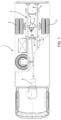
- Figure 1 shows a commercial or heavy vehicle 1 comprising a frame 2 extending along a longitudinal axis A and capable of moving by means of wheels 3 carried by an axle 4.
- the axle 4 comprises a carcass 5 defining a space 6 designed to at least partially accommodate a pair of axle shafts 7a, 7b extending along an B, which is transverse relative to the longitudinal axis A of the vehicle 1.
- axle shafts 7a, 7b are operatively connected, at an end of theirs, to a transmission 8 of the vehicle 1 and, on the opposite side, to respective wheel hubs 10.
- the transmission 8 shows a bevel gear, but it clearly could be any type of torque transmission device, such as a differential, operatively connected to a torque source 9, such as a power module, for example an internal combustion engine.
- wheel hubs 10 are carried by the carcass 5 so that they can freely rotate and are each configured to cooperate with the respective end portion of the axle shafts 7a, 7b, as described more in detail below.
- wheel hubs 10 for the sake of simplicity, reference will be made to only one of them, for example the right one, and the items of information provided below also apply - in the same way - to the left wheel hub, the structure described below obviously being mirror-like relative to a longitudinal axis A of the vehicle 1.
- the wheel hub 10 is supported in such a way that it can freely rotate relative to the carcass 5, in particular it is hollow and coaxial to the transverse axis B.
- the wheel hub 6 is supported by means of support means 11, such as a pair of conical bearings, and by means of sealing means 8, such as O-rings.
- the hub 10 comprises a main portion 10a with a substantially cylindrical shape, which is carried by the carcass 2, and an annular portion 10b, which is housed at an end portion of the carcass 5 and is carried by the main portion 10a.
- the main portion 10a and the annular portion 10b are coupled by means of known threaded means and, optionally, with the aid of further intermediate parts, which are not described in detail herein for they depend on the assembly, which is due to the type and the weight of the vehicle.
- the cylindrical portion 10a defines, together with the end part of the carcass 5, a chamber 13, which is axially delimited - along the axis B - by an axial wall 6c of the main portion 10a and, on the other side, by the end part of the carcass 5; said chamber 13 is radially delimited, around the axis B, by the inner surface of the main portion 10a of the wheel hub 10.
- the wheel hub 10 is operatively connected to the axle 4 by means of a reduction unit 15, which is housed inside the chamber 13 and is configured to connect the wheel hub 10 to the axle shaft 7b with several different gear ratios, namely so that the speed/torque delivered to the axle shaft 7b is different from the speed/torque delivered to the wheel hub 10.
- the wheel hub 10 is provided with a reduction unit 15, which allows for two different gear ratios between the axle shaft 7b and the wheel hub 10.
- the reduction unit 15 comprises a selector 16, which is coupled to the axle shaft 7b in a rotary manner and is configured to freely move on it along the axis B due to the action of actuator means 17, which are described below.
- the selector 16 is advantageously coupled to the axle shaft 7b by means of a grooved coupling 18, such as a splined coupling.
- the reduction unit 11 further comprises a gearing 21, which is configured to cooperate with the selector 16 according to a first and a second operating condition characterized by two different gear ratios between the axle shaft 7b and the wheel hub 10.
- the gearing 21 is an epicyclic gearing comprising a plurality of satellites 22, which are carried by pins 23 integral to a train carrier 24 connected to the hub 10 and are configured to mesh with a portion 25 integral to the carcass 5.
- the portion 25 integral to the carcass 5 is advantageously shaped like a bell open towards the chamber 13, so that it faces the axial wall 6c.
- the portion 25 is configured to accommodate, on the inside, the satellites 23.
- the portion 25 defines a toothing 26 configured to mesh with the satellites 23.
- the gearing 21 further comprises a sungear 27 carried in a rotary manner between the carcass 5 and the train carrier 24 and defining a toothing 28 designed to mesh with the satellites 23.
- the sungear 27 defines a toothing 31 and the train carrier 24 defines a toothing 32 configured to selectively cooperate with a toothing 33 integral to the selector 16.
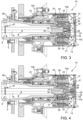
- the selector 16 is configured to move along the axis B so as to take on a first operating condition ( figure 3 ), in which the toothing 33 cooperates with the toothing 32 and makes the selector 16 integral to the train carrier 24, or a second operating condition ( figure 4 ), in which the toothing 33 cooperates with the toothing 31 and makes the selector 16 integral to the sungear 27.
- the selector 16 is caused to move between the first and the second operating condition by actuator means 17, which, in the embodiment shown herein, advantageously are pneumatic actuator means.
- the actuator means comprise a piston 35, which is carried, in a sliding and sealing manner, in a chamber 36 separate from the chamber 13 and is configured to cooperate in contact with the selector 16, which is free to rotate relative to it.
- the chamber 36 is divided into two portions, which are fluidly separated from one another by the piston 35.
- the chamber 13 is advantageously created by a structure 37, which is integral to the train carrier 24 and connects the latter to the axial wall 6c.
- the actuator means 17 described herein further comprise elastic means 38, which are configured to exert a force upon the piston 37 that is such that the latter is held in its first operating condition.
- the elastic means 38 comprise a helical spring accommodated between the axle shaft 7b and the selector 16.
- At least a portion of the chamber 36 is fluidly connected to a source of fluid under pressure (as better described below) by means of one or more conduits 41, which are configured to allow a fluid, such as compressed air, to be injected into or let out of the chamber 36.
- a fluid such as compressed air
- the gearing 21 is an epicyclic gearing comprising a plurality of satellites 22, which are carried by pins 23 carried, so that they can freely rotate, by a train carrier 24 connected to the wheel hub 10.
- the gearing 21 comprises a pair of toothed wheels 42, 43, one carried by the carcass 5 in an integral manner and the other supported so that it can freely rotate relative to the train carrier 24.
- the pair of toothed wheels 42, 43 and the satellites 22 define bevel gears.
- the he toothed wheel carried in an idle manner relative to the train carrier 24 defines a toothing 31 and the train carrier 24 defines a toothing 32 configured to selectively cooperate with a toothing 33 integral to the selector 16.
- the selector 16 is configured to move along the axis B so as to take on a first operating condition ( figure 6 ), in which the toothing 33 cooperates with the toothing 32 and makes the selector 16 integral to the train carrier 24, or a second operating condition ( figure 5 ), in which the toothing 33 cooperates with the toothing 31 and makes the selector 16 integral to the idle toothed wheel 43.
- the selector 16 is caused to move between the first and the second operating condition by actuator means 17, which, in the embodiment shown herein, advantageously are pneumatic actuator means.
- the actuator means comprise a piston 35, which is carried, in a sliding and sealing manner, in a chamber 36 separate from the chamber 13 and is configured to cooperate in contact with the selector 16, which is free to rotate relative to it.
- the chamber 13 is advantageously created by a structure 37, which is integral to the train carrier 24 and connects the latter to the axial wall 6c.
- the chamber 36 is fluidly connected to a source of fluid under pressure by means of one or more conduits 41, which are configured to allow a fluid, such as compressed air, to be injected into or let out of the chamber 36.
- a fluid such as compressed air
- the conduit 41 branches off into a pair of branches 41a, 41b configured to supply air to the chamber 36 in the two portions divided, in a sealed manner, by the sleeve 35, in an alternated manner.
- the vehicle 1 comprises a source of fluid under pressure 50, such as a tank of compressed air, fluidly connected to the conduits 41a, 41b, for example by means of respective valve means 51 configured to adjust the passage of air through them.
- a source of fluid under pressure 50 such as a tank of compressed air
- the vehicle 1 further comprises an electronic control unit 60 and a plurality of sensors 61-68 designed to detect quantities relating to different operating parameters of the vehicle, the control unit 60 comprises processing means electronically connected to the sensors 61-68 in order to acquire data detected by them and control, as a consequence, the passage of fluid under pressure 50 towards the conduits 41a, 41b.
- the control unit 60 comprises processing means electronically connected to the sensors 61-68 in order to acquire data detected by them and control, as a consequence, the passage of fluid under pressure 50 towards the conduits 41a, 41b.
- the sensors 61-68 can be connected to the control unit 60 via wire or in an electromagnetic manner and the control unit 60 is configured to control the valve means 51, which advantageously are solenoid valves.
- the electronic unit 60 contains stored data concerning the control of the actuator means 17.
- the vehicle 1 can further comprise control means (not shown) configured to change the data stored in the control unit 60 so as to change the actuation condition of the selector 16.
- the sensor means preferably comprise at least some of the following sensor means:
- the compressed air is caused flow from the conduit 41 to the chamber 36 moving the piston 35 and shifting it to the condition of figure 4 , namely on the opposite side relative to the axial wall 10c, and compressing the elastic means 38.
- the teeth 33 of the actuator 16 mesh with the teeth 31 of the sungear 27.
- torque is delivered to the satellites 22, which mesh with the element 25 and drag the pins 23, which are integral to the train carrier 24.
- the latter causes the rotation of the wheel hub 10.
- the torque delivered to the wheel hub 10 clearly is greater, even if at a lower speed.
- the compressed air is caused to flow through the conduit 41a, letting the air out of the other portion of chamber 36 through the conduit 41b or respective valve means.
- the piston 35 is moved to the condition of figure 5 , namely on the opposite side relative to the axial wall.
- the teeth 33 of the actuator 16 mesh with the teeth 31 of the toothed wheel 43, which meshes with the satellites 22 and the other toothed wheel 42.
- the satellites 22 are caused to rotate and drag the train carrier 24, which drags the wheel hub 10.
- the torque delivered to the wheel hub 10 clearly is greater, even if at a lower speed.
- the invention also relates to a method for controlling a wheel hub provided with a reduction unit 15 of the type described above.
- Said method basically comprises the following steps of:
- control of the actuator means 17 comprises sending a control signal to said valve means 51.
- the method described above can be stored and processed in the control unit 60 described above and the detected physical quantities can be some of the quantities detected by the sensor means 61-68.
- the check concerning the vehicle load condition can be carried out through a check of the detected quantities relative to physical quantities stored in the control unit 60, for example by means of lookup tables (LUT) deriving from specific experimental tests for the special type of vehicle.
- LUT lookup tables
- the aforesaid check can be carried out by means of a comparison relative to value deriving from mathematical interpolation among said physical quantities.
- a reduction system is provided, which is integrated in a wheel hub, is versatile, compact and economic as well as easy to be mounted and subjected to maintenance compared to known systems.
- the use of a gearing integrated in the wheel hub allows manufacturers to obtain high transmission ratios through a sturdy gear, which is suited for the large loads of an axle of a heavy vehicle.
- the presence of two conduits, which selectively inject air into two portion of the chamber of the actuator means, activates the reduction ratio shift in a quicker and more controlled manner.
- said shift can be controlled during the movement of the vehicle.
- the shift can take place in the reduction 15 when the vehicle is moving, avoiding scraping between the selector 16 and the toothings 31, 32.
- the control can be automated and stored in the electronic unit and the control variables can previously be stored or can be changed by the driver.
- wheel hub for an axle of a vehicle comprising an integrated reduction system according to the invention can be subjected to changes and variants, which, though, do not go beyond the scope of protection set forth in the appended claims.
- the carcass 4 and the wheel hub 10 can have different shapes and consist of more and different pieces.
- gears described above could change and there could be elements that are not described herein, but are known when dealing with the assembly of an axle according to the invention.
- equivalent actuator means being, for example, electromagnetic, mechanical or fluid actuator means, which are configured for the selector 16 instead of the air pressing force described herein.
- the method disclosed herein could comprise different ways to check for the condition of engagement of the gears between wheel hub and axle shafts, as mentioned above, through checks of limit values deriving from mathematical interpolations or table relationships.
- the two embodiments of the invention can be combined together and the presence of the elastic means would support the pressing force provided in the chamber 36 by an actuation system 17 provided with two conduits.
Landscapes
- Engineering & Computer Science (AREA)
- General Engineering & Computer Science (AREA)
- Mechanical Engineering (AREA)
- Chemical & Material Sciences (AREA)
- Combustion & Propulsion (AREA)
- Transportation (AREA)
- Arrangement And Mounting Of Devices That Control Transmission Of Motive Force (AREA)
Abstract
Description
- This patent application claims priority from
Italian patent application no. 102022000002885 filed on February 16, 2022 - The invention relates to a wheel hub for an axle of a vehicle, in particular a wheel hub for an axle of a heavy vehicle comprising a reduction system integrated in the hub.
- As it is known, in a wheel vehicle provided with at least one internal combustion engine, reducing the torque coming from the driving shaft relative to the axles of the vehicle is essential.
- As it is further known, vehicles are normally provided with a differential gear assembly, which is configured to differentiate the torque coming from the driving shaft between a pair of axle shafts of the axle, due to known reasons of dynamics while driving the vehicle.
- The aforementioned torque reduction is normally carried out by means of known gearbox devices arranged between the driving shaft and the aforesaid differential gear assembly.
- However, in case of heavy vehicles, these reduction gears are insufficient, in terms of number, to be able to provide a suitable reduction ratio between the torque of the driving shaft and the torque delivered to the wheels of the axle in the different load conditions.
- Indeed, it is clear that a heavy vehicle, such as a truck, has to bear a significant weight difference between the unloaded condition and the maximum load condition and, hence, the highest gears are not necessarily the most suited ones for the unloaded condition of the vehicle.
- To this aim, reduction systems are known, which are integrated in the wheel hubs. However, these systems require further improvements in order to increase their efficiency.
- Furthermore, known reduction systems do not allow the gears contained therein to be engaged while the vehicle is running, which means that the vehicle needs to be stopped, with a consequent increase in unproductive times.
- Therefore, there is a strong need for a reduction system for an axle of a vehicle, which can solve the problems discussed above.
- The object of the invention is to fulfil the aforementioned needs in an optimized and economic fashion.
- The aforesaid object is reached by a wheel hub for an axle provided with an integrated reduction system and by a vehicle according to the appended claims.
- The invention will be best understood upon perusal of the following detailed description of a preferred embodiment, which is provided by way of non-limiting example, with reference to the accompanying drawings, wherein:
-
Figure 1 is a schematic sectionals view from the top of a vehicle provided with wheel hubs according to the invention; -
Figure 2 is a schematic sectional view of an axle provided with wheel hubs according to a first embodiment of the invention; -
Figure 3 is a sectional view of a vehicle hub comprising a first embodiment of the invention in a first operating condition; -
Figure 4 is a sectional view of a vehicle hub comprising a first embodiment of the invention in a second operating condition; -
Figure 5 is a sectional view of a vehicle hub comprising a second embodiment of the invention in a first operating condition; -
Figure 6 is a sectional view of a vehicle hub comprising a second embodiment of the invention in a second operating condition; and -
Figure 7 is a schematic view of a control system for the vehicle hub offigures 5 and 6 . -
Figure 1 shows a commercial orheavy vehicle 1 comprising aframe 2 extending along a longitudinal axis A and capable of moving by means ofwheels 3 carried by anaxle 4. - A shown in
figure 2 , theaxle 4 comprises acarcass 5 defining aspace 6 designed to at least partially accommodate a pair ofaxle shafts vehicle 1. - In particular, the
axle shafts transmission 8 of thevehicle 1 and, on the opposite side, torespective wheel hubs 10. In the example shown herein, thetransmission 8 shows a bevel gear, but it clearly could be any type of torque transmission device, such as a differential, operatively connected to a torque source 9, such as a power module, for example an internal combustion engine. - In particular, the
wheel hubs 10 are carried by thecarcass 5 so that they can freely rotate and are each configured to cooperate with the respective end portion of theaxle shafts - As to the
wheel hubs 10, for the sake of simplicity, reference will be made to only one of them, for example the right one, and the items of information provided below also apply - in the same way - to the left wheel hub, the structure described below obviously being mirror-like relative to a longitudinal axis A of thevehicle 1. - The
wheel hub 10, as mentioned above, is supported in such a way that it can freely rotate relative to thecarcass 5, in particular it is hollow and coaxial to the transverse axis B. In the example described herein, thewheel hub 6 is supported by means of support means 11, such as a pair of conical bearings, and by means ofsealing means 8, such as O-rings. - In particular, the
hub 10 comprises amain portion 10a with a substantially cylindrical shape, which is carried by thecarcass 2, and anannular portion 10b, which is housed at an end portion of thecarcass 5 and is carried by themain portion 10a. Advantageously, themain portion 10a and theannular portion 10b are coupled by means of known threaded means and, optionally, with the aid of further intermediate parts, which are not described in detail herein for they depend on the assembly, which is due to the type and the weight of the vehicle. - The
cylindrical portion 10a defines, together with the end part of thecarcass 5, achamber 13, which is axially delimited - along the axis B - by an axial wall 6c of themain portion 10a and, on the other side, by the end part of thecarcass 5; saidchamber 13 is radially delimited, around the axis B, by the inner surface of themain portion 10a of thewheel hub 10. - The
wheel hub 10 is operatively connected to theaxle 4 by means of areduction unit 15, which is housed inside thechamber 13 and is configured to connect thewheel hub 10 to theaxle shaft 7b with several different gear ratios, namely so that the speed/torque delivered to theaxle shaft 7b is different from the speed/torque delivered to thewheel hub 10. - According to both embodiments shown herein, the
wheel hub 10 is provided with areduction unit 15, which allows for two different gear ratios between theaxle shaft 7b and thewheel hub 10. - In particular, the
reduction unit 15 comprises aselector 16, which is coupled to theaxle shaft 7b in a rotary manner and is configured to freely move on it along the axis B due to the action of actuator means 17, which are described below. Theselector 16 is advantageously coupled to theaxle shaft 7b by means of agrooved coupling 18, such as a splined coupling. - The
reduction unit 11 further comprises agearing 21, which is configured to cooperate with theselector 16 according to a first and a second operating condition characterized by two different gear ratios between theaxle shaft 7b and thewheel hub 10. - In the embodiment of
figures 3 and 4 , thegearing 21 is an epicyclic gearing comprising a plurality ofsatellites 22, which are carried bypins 23 integral to atrain carrier 24 connected to thehub 10 and are configured to mesh with aportion 25 integral to thecarcass 5. - In particular, the
portion 25 integral to thecarcass 5 is advantageously shaped like a bell open towards thechamber 13, so that it faces the axial wall 6c. Theportion 25 is configured to accommodate, on the inside, thesatellites 23. In particular, theportion 25 defines atoothing 26 configured to mesh with thesatellites 23. - The
gearing 21 further comprises asungear 27 carried in a rotary manner between thecarcass 5 and thetrain carrier 24 and defining a toothing 28 designed to mesh with thesatellites 23. - In particular, the
sungear 27 defines atoothing 31 and thetrain carrier 24 defines atoothing 32 configured to selectively cooperate with atoothing 33 integral to theselector 16. - The
selector 16 is configured to move along the axis B so as to take on a first operating condition (figure 3 ), in which thetoothing 33 cooperates with thetoothing 32 and makes theselector 16 integral to thetrain carrier 24, or a second operating condition (figure 4 ), in which thetoothing 33 cooperates with the toothing 31 and makes theselector 16 integral to thesungear 27. - The
selector 16 is caused to move between the first and the second operating condition by actuator means 17, which, in the embodiment shown herein, advantageously are pneumatic actuator means. - In particular, the actuator means comprise a
piston 35, which is carried, in a sliding and sealing manner, in achamber 36 separate from thechamber 13 and is configured to cooperate in contact with theselector 16, which is free to rotate relative to it. As a consequence, thechamber 36 is divided into two portions, which are fluidly separated from one another by thepiston 35. - The
chamber 13 is advantageously created by astructure 37, which is integral to thetrain carrier 24 and connects the latter to the axial wall 6c. - The actuator means 17 described herein further comprise
elastic means 38, which are configured to exert a force upon thepiston 37 that is such that the latter is held in its first operating condition. In particular, the elastic means 38 comprise a helical spring accommodated between theaxle shaft 7b and theselector 16. - At least a portion of the
chamber 36 is fluidly connected to a source of fluid under pressure (as better described below) by means of one ormore conduits 41, which are configured to allow a fluid, such as compressed air, to be injected into or let out of thechamber 36. - In the embodiment of
figures 3 and 4 there is onesingle conduit 41, which is configured to inject a fluid into or let it out of a same portion of thechamber 36. - In the embodiments of
figures 5 and 6 , thegearing 21 is an epicyclic gearing comprising a plurality ofsatellites 22, which are carried bypins 23 carried, so that they can freely rotate, by atrain carrier 24 connected to thewheel hub 10. - In particular, the
gearing 21 comprises a pair oftoothed wheels carcass 5 in an integral manner and the other supported so that it can freely rotate relative to thetrain carrier 24. In particular, the pair oftoothed wheels satellites 22 define bevel gears. - In particular, the he toothed wheel carried in an idle manner relative to the
train carrier 24 defines atoothing 31 and thetrain carrier 24 defines atoothing 32 configured to selectively cooperate with a toothing 33 integral to theselector 16. Theselector 16 is configured to move along the axis B so as to take on a first operating condition (figure 6 ), in which thetoothing 33 cooperates with thetoothing 32 and makes theselector 16 integral to thetrain carrier 24, or a second operating condition (figure 5 ), in which thetoothing 33 cooperates with the toothing 31 and makes theselector 16 integral to the idletoothed wheel 43. - The
selector 16 is caused to move between the first and the second operating condition by actuator means 17, which, in the embodiment shown herein, advantageously are pneumatic actuator means. - In particular, the actuator means comprise a
piston 35, which is carried, in a sliding and sealing manner, in achamber 36 separate from thechamber 13 and is configured to cooperate in contact with theselector 16, which is free to rotate relative to it. - The
chamber 13 is advantageously created by astructure 37, which is integral to thetrain carrier 24 and connects the latter to the axial wall 6c. - The
chamber 36 is fluidly connected to a source of fluid under pressure by means of one ormore conduits 41, which are configured to allow a fluid, such as compressed air, to be injected into or let out of thechamber 36. - Compared to the first embodiment, the
conduit 41 branches off into a pair ofbranches chamber 36 in the two portions divided, in a sealed manner, by thesleeve 35, in an alternated manner. - With reference to
figure 7 , thus to the second embodiment shown infigures 5 and 6 , thevehicle 1 comprises a source of fluid underpressure 50, such as a tank of compressed air, fluidly connected to theconduits - Advantageously, the
vehicle 1 further comprises anelectronic control unit 60 and a plurality of sensors 61-68 designed to detect quantities relating to different operating parameters of the vehicle, thecontrol unit 60 comprises processing means electronically connected to the sensors 61-68 in order to acquire data detected by them and control, as a consequence, the passage of fluid underpressure 50 towards theconduits - In particular, the sensors 61-68 can be connected to the
control unit 60 via wire or in an electromagnetic manner and thecontrol unit 60 is configured to control the valve means 51, which advantageously are solenoid valves. - In particular, the
electronic unit 60 contains stored data concerning the control of the actuator means 17. Thevehicle 1 can further comprise control means (not shown) configured to change the data stored in thecontrol unit 60 so as to change the actuation condition of theselector 16. - The sensor means preferably comprise at least some of the following sensor means:
- A
load sensor 61 configured to detect the load of a suspension connecting theaxle 4 to theframe 2, for example a load cell; - A
clutch sensor 62 configured to detect the opening of a control clutch of thetransmission 8, for example a position sensor connected to the clutch pedal; - An
accelerator sensor 63 configured to detect the acceleration of thevehicle 1, for example a position sensor connected to the accelerator pedal; - An
ignition sensor 64 configured to detect the ignition of thevehicle 1, for example a movement sensor of the key ignition system; - A
speed sensor 65 configured to detect a rotation speed of the output shaft of the power module 9, for example a phonic wheel; - A
command sensor 66 configured to detect the activation of the possibility of changing the ratio of the wheel hub, for example a button or an icon on a display; - A
speed sensor 67 configured to detect a rotation speed of theaxle 4, hence of theaxle shafts - A
speed sensor 68 configured to detect a speed of thewheel hub 10, such as an ABS sensor of the phonic wheel of encoder kind. - The operation of the embodiment of
figures 3 and 4 will now be described, assuming that the operating condition offigure 4 occurs. - In this operating condition, the
conduit 41 does not introduce air, thepiston 35 is maintained adjacent to the axis wall 6c by theelastic means 38. In this condition, theteeth 33 of theactuator 16 mesh with theteeth 32 of thetrain carrier 24. In this way, thewheel hub 10, which is integral to thetrain carrier 24, is caused to rotate by theaxle shaft 7b at the same speed as the latter. - In case it is needed, the compressed air is caused flow from the
conduit 41 to thechamber 36 moving thepiston 35 and shifting it to the condition offigure 4 , namely on the opposite side relative to theaxial wall 10c, and compressing theelastic means 38. Here, theteeth 33 of theactuator 16 mesh with theteeth 31 of thesungear 27. In this way, torque is delivered to thesatellites 22, which mesh with theelement 25 and drag thepins 23, which are integral to thetrain carrier 24. Hence, the latter causes the rotation of thewheel hub 10. In this condition, the torque delivered to thewheel hub 10 clearly is greater, even if at a lower speed. - In case a shift to the condition of
figure 3 is needed, pressure has to be released, through theconduit 41 or valve means provided in thewheel hub 10, from thechamber 36 so that thepiston 35 is moved back by the elastic means 38 to the first operating condition described above. - The operation of the embodiment of
figures 5 and 6 will now be described, assuming that the operating condition offigure 6 occurs. - In this operating condition, the
conduit 41b introduces air and thepiston 35 is maintained adjacent to the axis wall 6c. In this condition, theteeth 33 of theactuator 16 mesh with theteeth 32 of thetrain carrier 24. In this way, thewheel hub 10, which is integral to thetrain carrier 24, is caused to rotate by theaxle shaft 7b at the same speed as the latter. - In case it is needed, the compressed air is caused to flow through the
conduit 41a, letting the air out of the other portion ofchamber 36 through theconduit 41b or respective valve means. In this way, thepiston 35 is moved to the condition offigure 5 , namely on the opposite side relative to the axial wall. Here, theteeth 33 of theactuator 16 mesh with theteeth 31 of thetoothed wheel 43, which meshes with thesatellites 22 and the othertoothed wheel 42. Hence, thesatellites 22 are caused to rotate and drag thetrain carrier 24, which drags thewheel hub 10. In this condition, the torque delivered to thewheel hub 10 clearly is greater, even if at a lower speed. - In case a shift to the condition of
figure 6 is needed, the insertion and the release of the compressed fluid into and from thechamber 36 though theconduits piston 35 to the initial position. - According to the description above, the invention also relates to a method for controlling a wheel hub provided with a
reduction unit 15 of the type described above. - Said method basically comprises the following steps of:
- Detecting a plurality of physical quantities relating to operating parameters of the
vehicle 1; - Processing these detected physical quantities in order to identify a vehicle load condition;
- Checking whether the vehicle load condition complies with the reduction ratio of the
wheel hub 10; - If it complies, the ratio is maintained, otherwise the actuator means 17 are controlled so as to shift to a different reduction ratio.
- In particular, the control of the actuator means 17 comprises sending a control signal to said valve means 51.
- In particular, the method described above can be stored and processed in the
control unit 60 described above and the detected physical quantities can be some of the quantities detected by the sensor means 61-68. - The check concerning the vehicle load condition can be carried out through a check of the detected quantities relative to physical quantities stored in the
control unit 60, for example by means of lookup tables (LUT) deriving from specific experimental tests for the special type of vehicle. - Otherwise, the aforesaid check can be carried out by means of a comparison relative to value deriving from mathematical interpolation among said physical quantities.
- Owing to the above, the advantages of a wheel hub for an axle of a vehicle comprising an integrated reduction system according to the invention are evident.
- Thanks to this system, a reduction system is provided, which is integrated in a wheel hub, is versatile, compact and economic as well as easy to be mounted and subjected to maintenance compared to known systems.
- Thanks to the additional reduction system and to the reduction range that can be optimized depending on the type and size of the vehicle, fuel consumptions as well as pollutant emissions can be reduced.
- In particular, the use of a gearing integrated in the wheel hub allows manufacturers to obtain high transmission ratios through a sturdy gear, which is suited for the large loads of an axle of a heavy vehicle.
- Furthermore, the presence of two conduits, which selectively inject air into two portion of the chamber of the actuator means, activates the reduction ratio shift in a quicker and more controlled manner. In particular, said shift can be controlled during the movement of the vehicle.
- Indeed, thanks to the control method described herein, the shift can take place in the
reduction 15 when the vehicle is moving, avoiding scraping between theselector 16 and thetoothings - The control can be automated and stored in the electronic unit and the control variables can previously be stored or can be changed by the driver.
- Finally, the wheel hub for an axle of a vehicle comprising an integrated reduction system according to the invention can be subjected to changes and variants, which, though, do not go beyond the scope of protection set forth in the appended claims.
- Obviously, as mentioned above, the
carcass 4 and thewheel hub 10 can have different shapes and consist of more and different pieces. - In addition, the gears described above could change and there could be elements that are not described herein, but are known when dealing with the assembly of an axle according to the invention.
- Clearly, the description above relates to an air actuation, which is deemed to be the most effective and economic one, however the use of equivalent actuator means should not be excluded, said equivalent actuator means being, for example, electromagnetic, mechanical or fluid actuator means, which are configured for the
selector 16 instead of the air pressing force described herein. - Furthermore, the method disclosed herein could comprise different ways to check for the condition of engagement of the gears between wheel hub and axle shafts, as mentioned above, through checks of limit values deriving from mathematical interpolations or table relationships.
- Finally, the two embodiments of the invention can be combined together and the presence of the elastic means would support the pressing force provided in the
chamber 36 by anactuation system 17 provided with two conduits.
Claims (20)
- Wheel hub (10) for an axle (4) of a vehicle (1) comprising:- a hollow portion (10a) carried in a rotationally free manner on a carcass (5) of said axle (4) around an axis (B) of the latter, said portion (10a) defining a chamber (13) between its inner wall and said carcass (5),- a reduction unit (15) housed inside said chamber (13) and configured to vary the torque transmitted by a shaft (7a, 7b) of said axle (4) and said wheel hub (10), said reduction unit (15) comprising a gearing (21),- a selector (16) rotationally coupled to said shaft (7a, 7b) of said axle (4) and free to move on it along said axis (B),- actuator means (17) configured to control the position of said selector (16) along said axis (B),said gearing (15) comprising a carrier (24) integral with said portion (10a) and a plurality of satellites (22) meshing between said carcass (5) of said axle (4) said carrier (24),said selector (16) defining a toothing (33) configured to selectively mesh with a first toothing (32) integral with said chain carrier (24) and a second toothing (31) operatively connected to said satellites (22) according to the position of said selector (16) along said axis (B).
- Wheel hub according to claim 1, wherein said gearing (21) comprises a sungear (27) defining said second toothing (31), said sungear (27) being rotationally free between said carcass (5) and said train carrier (24).
- Wheel hub according to claim 2, wherein said satellites (22) mesh with respect to said sungear (27) and a toothing (28) made on a portion (25) fixed with respect to said carcass (5).
- Wheel hub according to claim 3, wherein said portion (25) defines a space housing said satellites (22) inside it.
- Wheel hub according to claim 1, wherein said gearing (21) comprises a toothed wheel (43) defining said second toothing (31), said toothed wheel (43) being rotationally free on said train carrier (24).
- Wheel hub according to claim 5, wherein said gearing (21) comprises a further toothed wheel (42) integral with said carcass (5), said satellites (22) meshing with said toothed wheels (42, 43).
- Wheel hub according to claim 6, wherein said toothed wheels (42, 43) and said satellites (22) define a bevel gear.
- Wheel hub according to one of the preceding claims, in which said actuator means (17) are of the pneumatic type and comprise a chamber (36) in which a piston (35) is free to slide and seal so as to divide said chamber (36) in two portions fluidically separated from each other, one of said portions being fluidically connected to a source (50) of pressurized fluid of said vehicle by means of a conduit (41).
- Wheel hub according to claim 8, wherein both of said portions being fluidically connected to a source (50) of pressurized fluid of said vehicle through respective ducts (41a, 41b).
- Wheel hub according to claim 8 or 9, in which said chamber (36) is defined by a structure (37) integral with said train carrier (24).
- Wheel hub according to claim 8, comprising elastic means (38) operatively interposed between said piston (35) and said actuator (16) and configured to impart a force capable of maintaining said toothing (33) of said selector (16) with one of said first or second teeth (31, 32) when said chamber (35) does not contain said fluid under pressure.
- Axle (4) for vehicle comprising:- a carcass (5) defining a space (6) along an axis (B) ;- a pair of shafts (7a, 7b) housed at least partially in said space (6) and comprising respective internal ends cooperating with a transmission (8) of said vehicle (1) configured to supply a driving torque to said shafts (7a, 7b) ;- respective wheel hubs (10) carried in a rotationally free manner by said carcass (5) made according to one of the preceding claims.
- Vehicle (1) comprising a frame (2), a power module (9), a transmission (8) and at least one axle (4) according to claim 12.
- Vehicle according to Claim 13, comprising a source of pressurized fluid (50) fluidically connected through at least one duct (41; 41a, 41b) with said actuator means (17) and valve means (51) fluidically interposed on said at least a duct (41; 41a, 41b) for regulating the passage of fluid under pressure therein.
- Vehicle according to Claim 14, comprising a control unit (60) and a plurality of sensor means (61-68) configured to detect physical quantities relating to operational conditions of said vehicle (1), said control unit (60) comprising processing means electrically connected to said sensor means (61-68) for acquiring the data detected by them, processing them and consequently controlling said valve means (51) as a function of data relating to said operational conditions stored in said processing means.
- Vehicle according to Claim 15, comprising control means configured to vary the data stored in said electronic unit (60) relating to said operating quantities.
- Vehicle according to claim 15 or 16, comprising at least some of the following sensor means (61-68):• A load sensor (61) configured to detect the load of a suspension connecting said axle (4) to said frame;• A clutch sensor (62) configured to detect the opening of a control clutch of said transmission (8) ;• An accelerator sensor (63) configured to detect the acceleration of said vehicle (1);• An ignition sensor (64) configured to detect the ignition of said vehicle (1);• A speed sensor (65) configured to detect a rotation speed of an output shaft of said power module (9);• A command sensor (66) configured to detect the activation of the possibility of varying the ratio of said wheel hub (10)• A speed sensor (67) configured to detect the speed of said shafts (7a, 7b); And• A speed sensor (68), configured to detect a speed of said wheel hub (10).
- Method for controlling a wheel hub (10) in a vehicle according to claim 17, comprising the following steps:• detecting a plurality of physical quantities relating to operating parameters of said vehicle (1);• Process these physical quantities detected to identify a vehicular load condition;• Check whether the vehicle load condition is in compliance with the reduction ratio of said wheel hub (10) ;• If it conforms, said ratio is maintained, otherwise said actuator means (17) are controlled to pass to a different reduction ratio.
- Method according to claim 18, wherein said control of said actuator means (17) comprises sending a signal to control said valve means (51).
- Method according to claim 18 or 19, wherein said verification of vehicle load condition comprises comparison with values stored in said control unit (60) and/or comparison with respect to a calculation through mathematical interpolation of said physical quantities.
Applications Claiming Priority (1)
| Application Number | Priority Date | Filing Date | Title |
|---|---|---|---|
| IT102022000002885A IT202200002885A1 (en) | 2022-02-16 | 2022-02-16 | VEHICLE AXLE WHEEL HUB INCLUDING AN IMPROVED INTEGRATED REDUCTION SYSTEM |
Publications (2)
| Publication Number | Publication Date |
|---|---|
| EP4230460A1 true EP4230460A1 (en) | 2023-08-23 |
| EP4230460B1 EP4230460B1 (en) | 2025-04-02 |
Family
ID=81392611
Family Applications (1)
| Application Number | Title | Priority Date | Filing Date |
|---|---|---|---|
| EP23156491.5A Active EP4230460B1 (en) | 2022-02-16 | 2023-02-14 | Wheel hub for an axle of a vehicle comprising an improved integrated reduction system |
Country Status (2)
| Country | Link |
|---|---|
| EP (1) | EP4230460B1 (en) |
| IT (1) | IT202200002885A1 (en) |
Cited By (3)
| Publication number | Priority date | Publication date | Assignee | Title |
|---|---|---|---|---|
| IT202300021297A1 (en) * | 2023-10-12 | 2025-04-12 | Iveco Spa | WHEEL HUB FOR VEHICLE AXLE INCLUDING AN IMPROVED INTEGRATED REDUCTION SYSTEM |
| EP4733112A1 (en) * | 2024-10-25 | 2026-04-29 | Iveco S.P.A. | Wheel hub for vehicle axle comprising an improved integrated reduction system |
| EP4733106A1 (en) * | 2024-10-25 | 2026-04-29 | Iveco S.P.A. | Wheel hub for vehicle axle comprising an improved integrated reduction system |
Citations (3)
| Publication number | Priority date | Publication date | Assignee | Title |
|---|---|---|---|---|
| FR1597388A (en) * | 1968-12-30 | 1970-06-22 | ||
| WO2016110823A1 (en) * | 2015-01-08 | 2016-07-14 | Iveco Latin America Ltda. | Reduction system applied to a wheel hub, and more particularly to a wheel hub connected to a differential of a goods vehicle |
| WO2021165913A1 (en) * | 2020-02-20 | 2021-08-26 | Iveco S.P.A. | Vehicle axle comprising an improved integrated reducing gear system |
-
2022
- 2022-02-16 IT IT102022000002885A patent/IT202200002885A1/en unknown
-
2023
- 2023-02-14 EP EP23156491.5A patent/EP4230460B1/en active Active
Patent Citations (3)
| Publication number | Priority date | Publication date | Assignee | Title |
|---|---|---|---|---|
| FR1597388A (en) * | 1968-12-30 | 1970-06-22 | ||
| WO2016110823A1 (en) * | 2015-01-08 | 2016-07-14 | Iveco Latin America Ltda. | Reduction system applied to a wheel hub, and more particularly to a wheel hub connected to a differential of a goods vehicle |
| WO2021165913A1 (en) * | 2020-02-20 | 2021-08-26 | Iveco S.P.A. | Vehicle axle comprising an improved integrated reducing gear system |
Cited By (4)
| Publication number | Priority date | Publication date | Assignee | Title |
|---|---|---|---|---|
| IT202300021297A1 (en) * | 2023-10-12 | 2025-04-12 | Iveco Spa | WHEEL HUB FOR VEHICLE AXLE INCLUDING AN IMPROVED INTEGRATED REDUCTION SYSTEM |
| EP4538087A1 (en) * | 2023-10-12 | 2025-04-16 | Iveco S.P.A. | Wheel hub for axle of a vehicle comprising an improved integrated reduction system |
| EP4733112A1 (en) * | 2024-10-25 | 2026-04-29 | Iveco S.P.A. | Wheel hub for vehicle axle comprising an improved integrated reduction system |
| EP4733106A1 (en) * | 2024-10-25 | 2026-04-29 | Iveco S.P.A. | Wheel hub for vehicle axle comprising an improved integrated reduction system |
Also Published As
| Publication number | Publication date |
|---|---|
| EP4230460B1 (en) | 2025-04-02 |
| IT202200002885A1 (en) | 2023-08-16 |
Similar Documents
| Publication | Publication Date | Title |
|---|---|---|
| EP4230460B1 (en) | Wheel hub for an axle of a vehicle comprising an improved integrated reduction system | |
| US7294086B2 (en) | Hydraulic control system for multiple clutches in a motor vehicle | |
| EP0413436B1 (en) | Torque distribution control system for a four-wheel drive motor vehicle | |
| US7086982B2 (en) | Torque vectoring drive axle assembly | |
| CN105805261B (en) | The double clutch drive module activated with single servo-fluid press pump and normally open valve | |
| GB2434418A (en) | Transaxle with hydraulic seals adjacent a halfshaft | |
| US20060011001A1 (en) | Differential drive actuator | |
| US5098351A (en) | Torque distribution control system for a four-wheel drive motor vehicle | |
| EP3333001A1 (en) | Shaft connection for a vehicle | |
| EP4538086A1 (en) | Wheel hub for axle of a vehicle comprising an improved integrated reduction system | |
| US7059990B2 (en) | Torque vectoring drive axle assembly | |
| GB2431442A (en) | Powertrain with transfer clutch control system in a transaxle case | |
| KR102617112B1 (en) | Electro-hydraulic limited slip differential system | |
| EP4279765A1 (en) | Wheel hub for a vehicle axle comprising an improved integrated reduction system | |
| EP3925811A1 (en) | Wheel hub for an axle of a vehicle comprising an improved integrated reduction system | |
| KR20250009444A (en) | Wheel hub for an axle of an automobile including an improved integrated reduction system | |
| EP4107023B1 (en) | Vehicle axle comprising an improved integrated reducing gear system | |
| US6364045B1 (en) | Front wheel drive clutch for tractors | |
| EP4538087A1 (en) | Wheel hub for axle of a vehicle comprising an improved integrated reduction system | |
| EP4733112A1 (en) | Wheel hub for vehicle axle comprising an improved integrated reduction system | |
| EP4733106A1 (en) | Wheel hub for vehicle axle comprising an improved integrated reduction system | |
| US10245946B2 (en) | Platform heavy duty transfer case | |
| EP3868593B1 (en) | Power-transmission axle for vehicle and vehicle | |
| EP3789224A1 (en) | Electric modular traction system |
Legal Events
| Date | Code | Title | Description |
|---|---|---|---|
| PUAI | Public reference made under article 153(3) epc to a published international application that has entered the european phase |
Free format text: ORIGINAL CODE: 0009012 |
|
| STAA | Information on the status of an ep patent application or granted ep patent |
Free format text: STATUS: THE APPLICATION HAS BEEN PUBLISHED |
|
| AK | Designated contracting states |
Kind code of ref document: A1 Designated state(s): AL AT BE BG CH CY CZ DE DK EE ES FI FR GB GR HR HU IE IS IT LI LT LU LV MC ME MK MT NL NO PL PT RO RS SE SI SK SM TR |
|
| STAA | Information on the status of an ep patent application or granted ep patent |
Free format text: STATUS: REQUEST FOR EXAMINATION WAS MADE |
|
| 17P | Request for examination filed |
Effective date: 20240219 |
|
| RBV | Designated contracting states (corrected) |
Designated state(s): AL AT BE BG CH CY CZ DE DK EE ES FI FR GB GR HR HU IE IS IT LI LT LU LV MC ME MK MT NL NO PL PT RO RS SE SI SK SM TR |
|
| REG | Reference to a national code |
Ref country code: DE Ref legal event code: R079 Free format text: PREVIOUS MAIN CLASS: B60K0017040000 Ipc: F16H0003500000 Ref country code: DE Ref legal event code: R079 Ref document number: 602023002641 Country of ref document: DE Free format text: PREVIOUS MAIN CLASS: B60K0017040000 Ipc: F16H0003500000 |
|
| GRAP | Despatch of communication of intention to grant a patent |
Free format text: ORIGINAL CODE: EPIDOSNIGR1 |
|
| STAA | Information on the status of an ep patent application or granted ep patent |
Free format text: STATUS: GRANT OF PATENT IS INTENDED |
|
| RIC1 | Information provided on ipc code assigned before grant |
Ipc: F16H 3/54 20060101ALI20241002BHEP Ipc: B60K 17/04 20060101ALI20241002BHEP Ipc: F16H 3/50 20060101AFI20241002BHEP |
|
| INTG | Intention to grant announced |
Effective date: 20241023 |
|
| P01 | Opt-out of the competence of the unified patent court (upc) registered |
Free format text: CASE NUMBER: APP_60581/2024 Effective date: 20241111 |
|
| GRAS | Grant fee paid |
Free format text: ORIGINAL CODE: EPIDOSNIGR3 |
|
| GRAA | (expected) grant |
Free format text: ORIGINAL CODE: 0009210 |
|
| STAA | Information on the status of an ep patent application or granted ep patent |
Free format text: STATUS: THE PATENT HAS BEEN GRANTED |
|
| AK | Designated contracting states |
Kind code of ref document: B1 Designated state(s): AL AT BE BG CH CY CZ DE DK EE ES FI FR GB GR HR HU IE IS IT LI LT LU LV MC ME MK MT NL NO PL PT RO RS SE SI SK SM TR |
|
| REG | Reference to a national code |
Ref country code: GB Ref legal event code: FG4D |
|
| REG | Reference to a national code |
Ref country code: CH Ref legal event code: EP |
|
| REG | Reference to a national code |
Ref country code: DE Ref legal event code: R096 Ref document number: 602023002641 Country of ref document: DE |
|
| REG | Reference to a national code |
Ref country code: IE Ref legal event code: FG4D |
|
| REG | Reference to a national code |
Ref country code: NL Ref legal event code: MP Effective date: 20250402 |
|
| PG25 | Lapsed in a contracting state [announced via postgrant information from national office to epo] |
Ref country code: NL Free format text: LAPSE BECAUSE OF FAILURE TO SUBMIT A TRANSLATION OF THE DESCRIPTION OR TO PAY THE FEE WITHIN THE PRESCRIBED TIME-LIMIT Effective date: 20250402 |
|
| REG | Reference to a national code |
Ref country code: AT Ref legal event code: MK05 Ref document number: 1781523 Country of ref document: AT Kind code of ref document: T Effective date: 20250402 |
|
| PG25 | Lapsed in a contracting state [announced via postgrant information from national office to epo] |
Ref country code: FI Free format text: LAPSE BECAUSE OF FAILURE TO SUBMIT A TRANSLATION OF THE DESCRIPTION OR TO PAY THE FEE WITHIN THE PRESCRIBED TIME-LIMIT Effective date: 20250402 Ref country code: ES Free format text: LAPSE BECAUSE OF FAILURE TO SUBMIT A TRANSLATION OF THE DESCRIPTION OR TO PAY THE FEE WITHIN THE PRESCRIBED TIME-LIMIT Effective date: 20250402 Ref country code: PT Free format text: LAPSE BECAUSE OF FAILURE TO SUBMIT A TRANSLATION OF THE DESCRIPTION OR TO PAY THE FEE WITHIN THE PRESCRIBED TIME-LIMIT Effective date: 20250804 |
|
| REG | Reference to a national code |
Ref country code: LT Ref legal event code: MG9D |
|
| PG25 | Lapsed in a contracting state [announced via postgrant information from national office to epo] |
Ref country code: GR Free format text: LAPSE BECAUSE OF FAILURE TO SUBMIT A TRANSLATION OF THE DESCRIPTION OR TO PAY THE FEE WITHIN THE PRESCRIBED TIME-LIMIT Effective date: 20250703 Ref country code: NO Free format text: LAPSE BECAUSE OF FAILURE TO SUBMIT A TRANSLATION OF THE DESCRIPTION OR TO PAY THE FEE WITHIN THE PRESCRIBED TIME-LIMIT Effective date: 20250702 |
|
| PG25 | Lapsed in a contracting state [announced via postgrant information from national office to epo] |
Ref country code: PL Free format text: LAPSE BECAUSE OF FAILURE TO SUBMIT A TRANSLATION OF THE DESCRIPTION OR TO PAY THE FEE WITHIN THE PRESCRIBED TIME-LIMIT Effective date: 20250402 |
|
| PG25 | Lapsed in a contracting state [announced via postgrant information from national office to epo] |
Ref country code: BG Free format text: LAPSE BECAUSE OF FAILURE TO SUBMIT A TRANSLATION OF THE DESCRIPTION OR TO PAY THE FEE WITHIN THE PRESCRIBED TIME-LIMIT Effective date: 20250402 |
|
| PG25 | Lapsed in a contracting state [announced via postgrant information from national office to epo] |
Ref country code: HR Free format text: LAPSE BECAUSE OF FAILURE TO SUBMIT A TRANSLATION OF THE DESCRIPTION OR TO PAY THE FEE WITHIN THE PRESCRIBED TIME-LIMIT Effective date: 20250402 |
|
| PG25 | Lapsed in a contracting state [announced via postgrant information from national office to epo] |
Ref country code: AT Free format text: LAPSE BECAUSE OF FAILURE TO SUBMIT A TRANSLATION OF THE DESCRIPTION OR TO PAY THE FEE WITHIN THE PRESCRIBED TIME-LIMIT Effective date: 20250402 |
|
| PG25 | Lapsed in a contracting state [announced via postgrant information from national office to epo] |
Ref country code: RS Free format text: LAPSE BECAUSE OF FAILURE TO SUBMIT A TRANSLATION OF THE DESCRIPTION OR TO PAY THE FEE WITHIN THE PRESCRIBED TIME-LIMIT Effective date: 20250702 |
|
| PG25 | Lapsed in a contracting state [announced via postgrant information from national office to epo] |
Ref country code: IS Free format text: LAPSE BECAUSE OF FAILURE TO SUBMIT A TRANSLATION OF THE DESCRIPTION OR TO PAY THE FEE WITHIN THE PRESCRIBED TIME-LIMIT Effective date: 20250802 |
|
| PG25 | Lapsed in a contracting state [announced via postgrant information from national office to epo] |
Ref country code: LV Free format text: LAPSE BECAUSE OF FAILURE TO SUBMIT A TRANSLATION OF THE DESCRIPTION OR TO PAY THE FEE WITHIN THE PRESCRIBED TIME-LIMIT Effective date: 20250402 |
|
| REG | Reference to a national code |
Ref country code: DE Ref legal event code: R097 Ref document number: 602023002641 Country of ref document: DE |
|
| PG25 | Lapsed in a contracting state [announced via postgrant information from national office to epo] |
Ref country code: DK Free format text: LAPSE BECAUSE OF FAILURE TO SUBMIT A TRANSLATION OF THE DESCRIPTION OR TO PAY THE FEE WITHIN THE PRESCRIBED TIME-LIMIT Effective date: 20250402 Ref country code: SM Free format text: LAPSE BECAUSE OF FAILURE TO SUBMIT A TRANSLATION OF THE DESCRIPTION OR TO PAY THE FEE WITHIN THE PRESCRIBED TIME-LIMIT Effective date: 20250402 |
|
| PG25 | Lapsed in a contracting state [announced via postgrant information from national office to epo] |
Ref country code: CZ Free format text: LAPSE BECAUSE OF FAILURE TO SUBMIT A TRANSLATION OF THE DESCRIPTION OR TO PAY THE FEE WITHIN THE PRESCRIBED TIME-LIMIT Effective date: 20250402 |
|
| PG25 | Lapsed in a contracting state [announced via postgrant information from national office to epo] |
Ref country code: EE Free format text: LAPSE BECAUSE OF FAILURE TO SUBMIT A TRANSLATION OF THE DESCRIPTION OR TO PAY THE FEE WITHIN THE PRESCRIBED TIME-LIMIT Effective date: 20250402 |
|
| PG25 | Lapsed in a contracting state [announced via postgrant information from national office to epo] |
Ref country code: SK Free format text: LAPSE BECAUSE OF FAILURE TO SUBMIT A TRANSLATION OF THE DESCRIPTION OR TO PAY THE FEE WITHIN THE PRESCRIBED TIME-LIMIT Effective date: 20250402 |
|
| PLBE | No opposition filed within time limit |
Free format text: ORIGINAL CODE: 0009261 |
|
| STAA | Information on the status of an ep patent application or granted ep patent |
Free format text: STATUS: NO OPPOSITION FILED WITHIN TIME LIMIT |
|
| REG | Reference to a national code |
Ref country code: CH Ref legal event code: L10 Free format text: ST27 STATUS EVENT CODE: U-0-0-L10-L00 (AS PROVIDED BY THE NATIONAL OFFICE) Effective date: 20260211 |
|
| 26N | No opposition filed |
Effective date: 20260105 |
|
| PGFP | Annual fee paid to national office [announced via postgrant information from national office to epo] |
Ref country code: DE Payment date: 20260220 Year of fee payment: 4 |
|
| PGFP | Annual fee paid to national office [announced via postgrant information from national office to epo] |
Ref country code: IT Payment date: 20260228 Year of fee payment: 4 |
|
| PGFP | Annual fee paid to national office [announced via postgrant information from national office to epo] |
Ref country code: FR Payment date: 20260227 Year of fee payment: 4 |