EP4230447A1 - Vehicle posture control device and vehicle - Google Patents
Vehicle posture control device and vehicle Download PDFInfo
- Publication number
- EP4230447A1 EP4230447A1 EP21879952.6A EP21879952A EP4230447A1 EP 4230447 A1 EP4230447 A1 EP 4230447A1 EP 21879952 A EP21879952 A EP 21879952A EP 4230447 A1 EP4230447 A1 EP 4230447A1
- Authority
- EP
- European Patent Office
- Prior art keywords
- vehicle
- roll
- moment
- control device
- pitch
- Prior art date
- Legal status (The legal status is an assumption and is not a legal conclusion. Google has not performed a legal analysis and makes no representation as to the accuracy of the status listed.)
- Withdrawn
Links
- 230000033001 locomotion Effects 0.000 claims abstract description 91
- 239000000725 suspension Substances 0.000 claims description 85
- 230000008859 change Effects 0.000 claims description 16
- 230000004044 response Effects 0.000 claims description 16
- 230000005484 gravity Effects 0.000 claims description 14
- 230000009189 diving Effects 0.000 claims description 12
- 239000000470 constituent Substances 0.000 claims description 9
- 230000001133 acceleration Effects 0.000 description 45
- 239000003381 stabilizer Substances 0.000 description 35
- 238000010586 diagram Methods 0.000 description 19
- 238000013016 damping Methods 0.000 description 18
- 238000004364 calculation method Methods 0.000 description 14
- 230000007246 mechanism Effects 0.000 description 9
- 230000002708 enhancing effect Effects 0.000 description 7
- 239000006096 absorbing agent Substances 0.000 description 6
- 230000035939 shock Effects 0.000 description 6
- 238000000034 method Methods 0.000 description 5
- 238000012360 testing method Methods 0.000 description 5
- 238000013459 approach Methods 0.000 description 4
- 238000005259 measurement Methods 0.000 description 4
- 238000004088 simulation Methods 0.000 description 4
- 238000007792 addition Methods 0.000 description 3
- 239000003638 chemical reducing agent Substances 0.000 description 2
- 238000012937 correction Methods 0.000 description 2
- 230000003111 delayed effect Effects 0.000 description 2
- 238000013461 design Methods 0.000 description 2
- 230000000694 effects Effects 0.000 description 2
- 238000011160 research Methods 0.000 description 2
- 238000013519 translation Methods 0.000 description 2
- 101000582320 Homo sapiens Neurogenic differentiation factor 6 Proteins 0.000 description 1
- 102100030589 Neurogenic differentiation factor 6 Human genes 0.000 description 1
- 230000008878 coupling Effects 0.000 description 1
- 238000010168 coupling process Methods 0.000 description 1
- 238000005859 coupling reaction Methods 0.000 description 1
- 238000012217 deletion Methods 0.000 description 1
- 230000037430 deletion Effects 0.000 description 1
- 238000006073 displacement reaction Methods 0.000 description 1
- 238000002474 experimental method Methods 0.000 description 1
- 230000001939 inductive effect Effects 0.000 description 1
- 238000012986 modification Methods 0.000 description 1
- 230000004048 modification Effects 0.000 description 1
- 230000002787 reinforcement Effects 0.000 description 1
- 230000004043 responsiveness Effects 0.000 description 1
- 238000009987 spinning Methods 0.000 description 1
- 238000012546 transfer Methods 0.000 description 1
- 230000001052 transient effect Effects 0.000 description 1
Images




Classifications
-
- B—PERFORMING OPERATIONS; TRANSPORTING
- B60—VEHICLES IN GENERAL
- B60W—CONJOINT CONTROL OF VEHICLE SUB-UNITS OF DIFFERENT TYPE OR DIFFERENT FUNCTION; CONTROL SYSTEMS SPECIALLY ADAPTED FOR HYBRID VEHICLES; ROAD VEHICLE DRIVE CONTROL SYSTEMS FOR PURPOSES NOT RELATED TO THE CONTROL OF A PARTICULAR SUB-UNIT
- B60W30/00—Purposes of road vehicle drive control systems not related to the control of a particular sub-unit, e.g. of systems using conjoint control of vehicle sub-units
- B60W30/02—Control of vehicle driving stability
-
- B—PERFORMING OPERATIONS; TRANSPORTING
- B60—VEHICLES IN GENERAL
- B60G—VEHICLE SUSPENSION ARRANGEMENTS
- B60G17/00—Resilient suspensions having means for adjusting the spring or vibration-damper characteristics, for regulating the distance between a supporting surface and a sprung part of vehicle or for locking suspension during use to meet varying vehicular or surface conditions, e.g. due to speed or load
- B60G17/015—Resilient suspensions having means for adjusting the spring or vibration-damper characteristics, for regulating the distance between a supporting surface and a sprung part of vehicle or for locking suspension during use to meet varying vehicular or surface conditions, e.g. due to speed or load the regulating means comprising electric or electronic elements
-
- B—PERFORMING OPERATIONS; TRANSPORTING
- B60—VEHICLES IN GENERAL
- B60G—VEHICLE SUSPENSION ARRANGEMENTS
- B60G17/00—Resilient suspensions having means for adjusting the spring or vibration-damper characteristics, for regulating the distance between a supporting surface and a sprung part of vehicle or for locking suspension during use to meet varying vehicular or surface conditions, e.g. due to speed or load
- B60G17/015—Resilient suspensions having means for adjusting the spring or vibration-damper characteristics, for regulating the distance between a supporting surface and a sprung part of vehicle or for locking suspension during use to meet varying vehicular or surface conditions, e.g. due to speed or load the regulating means comprising electric or electronic elements
- B60G17/016—Resilient suspensions having means for adjusting the spring or vibration-damper characteristics, for regulating the distance between a supporting surface and a sprung part of vehicle or for locking suspension during use to meet varying vehicular or surface conditions, e.g. due to speed or load the regulating means comprising electric or electronic elements characterised by their responsiveness, when the vehicle is travelling, to specific motion, a specific condition, or driver input
-
- B—PERFORMING OPERATIONS; TRANSPORTING
- B60—VEHICLES IN GENERAL
- B60G—VEHICLE SUSPENSION ARRANGEMENTS
- B60G17/00—Resilient suspensions having means for adjusting the spring or vibration-damper characteristics, for regulating the distance between a supporting surface and a sprung part of vehicle or for locking suspension during use to meet varying vehicular or surface conditions, e.g. due to speed or load
- B60G17/015—Resilient suspensions having means for adjusting the spring or vibration-damper characteristics, for regulating the distance between a supporting surface and a sprung part of vehicle or for locking suspension during use to meet varying vehicular or surface conditions, e.g. due to speed or load the regulating means comprising electric or electronic elements
- B60G17/018—Resilient suspensions having means for adjusting the spring or vibration-damper characteristics, for regulating the distance between a supporting surface and a sprung part of vehicle or for locking suspension during use to meet varying vehicular or surface conditions, e.g. due to speed or load the regulating means comprising electric or electronic elements characterised by the use of a specific signal treatment or control method
- B60G17/0182—Resilient suspensions having means for adjusting the spring or vibration-damper characteristics, for regulating the distance between a supporting surface and a sprung part of vehicle or for locking suspension during use to meet varying vehicular or surface conditions, e.g. due to speed or load the regulating means comprising electric or electronic elements characterised by the use of a specific signal treatment or control method involving parameter estimation, e.g. observer, Kalman filter
-
- B—PERFORMING OPERATIONS; TRANSPORTING
- B60—VEHICLES IN GENERAL
- B60G—VEHICLE SUSPENSION ARRANGEMENTS
- B60G17/00—Resilient suspensions having means for adjusting the spring or vibration-damper characteristics, for regulating the distance between a supporting surface and a sprung part of vehicle or for locking suspension during use to meet varying vehicular or surface conditions, e.g. due to speed or load
- B60G17/015—Resilient suspensions having means for adjusting the spring or vibration-damper characteristics, for regulating the distance between a supporting surface and a sprung part of vehicle or for locking suspension during use to meet varying vehicular or surface conditions, e.g. due to speed or load the regulating means comprising electric or electronic elements
- B60G17/0195—Resilient suspensions having means for adjusting the spring or vibration-damper characteristics, for regulating the distance between a supporting surface and a sprung part of vehicle or for locking suspension during use to meet varying vehicular or surface conditions, e.g. due to speed or load the regulating means comprising electric or electronic elements characterised by the regulation being combined with other vehicle control systems
-
- B—PERFORMING OPERATIONS; TRANSPORTING
- B60—VEHICLES IN GENERAL
- B60G—VEHICLE SUSPENSION ARRANGEMENTS
- B60G21/00—Interconnection systems for two or more resiliently-suspended wheels, e.g. for stabilising a vehicle body with respect to acceleration, deceleration or centrifugal forces
- B60G21/02—Interconnection systems for two or more resiliently-suspended wheels, e.g. for stabilising a vehicle body with respect to acceleration, deceleration or centrifugal forces permanently interconnected
- B60G21/04—Interconnection systems for two or more resiliently-suspended wheels, e.g. for stabilising a vehicle body with respect to acceleration, deceleration or centrifugal forces permanently interconnected mechanically
- B60G21/05—Interconnection systems for two or more resiliently-suspended wheels, e.g. for stabilising a vehicle body with respect to acceleration, deceleration or centrifugal forces permanently interconnected mechanically between wheels on the same axle but on different sides of the vehicle, i.e. the left and right wheel suspensions being interconnected
- B60G21/055—Stabiliser bars
- B60G21/0551—Mounting means therefor
- B60G21/0553—Mounting means therefor adjustable
- B60G21/0555—Mounting means therefor adjustable including an actuator inducing vehicle roll
-
- B—PERFORMING OPERATIONS; TRANSPORTING
- B60—VEHICLES IN GENERAL
- B60T—VEHICLE BRAKE CONTROL SYSTEMS OR PARTS THEREOF; BRAKE CONTROL SYSTEMS OR PARTS THEREOF, IN GENERAL; ARRANGEMENT OF BRAKING ELEMENTS ON VEHICLES IN GENERAL; PORTABLE DEVICES FOR PREVENTING UNWANTED MOVEMENT OF VEHICLES; VEHICLE MODIFICATIONS TO FACILITATE COOLING OF BRAKES
- B60T8/00—Arrangements for adjusting wheel-braking force to meet varying vehicular or ground-surface conditions, e.g. limiting or varying distribution of braking force
- B60T8/17—Using electrical or electronic regulation means to control braking
- B60T8/1755—Brake regulation specially adapted to control the stability of the vehicle, e.g. taking into account yaw rate or transverse acceleration in a curve
- B60T8/17554—Brake regulation specially adapted to control the stability of the vehicle, e.g. taking into account yaw rate or transverse acceleration in a curve specially adapted for enhancing stability around the vehicles longitudinal axle, i.e. roll-over prevention
-
- B—PERFORMING OPERATIONS; TRANSPORTING
- B60—VEHICLES IN GENERAL
- B60W—CONJOINT CONTROL OF VEHICLE SUB-UNITS OF DIFFERENT TYPE OR DIFFERENT FUNCTION; CONTROL SYSTEMS SPECIALLY ADAPTED FOR HYBRID VEHICLES; ROAD VEHICLE DRIVE CONTROL SYSTEMS FOR PURPOSES NOT RELATED TO THE CONTROL OF A PARTICULAR SUB-UNIT
- B60W10/00—Conjoint control of vehicle sub-units of different type or different function
- B60W10/18—Conjoint control of vehicle sub-units of different type or different function including control of braking systems
-
- B—PERFORMING OPERATIONS; TRANSPORTING
- B60—VEHICLES IN GENERAL
- B60W—CONJOINT CONTROL OF VEHICLE SUB-UNITS OF DIFFERENT TYPE OR DIFFERENT FUNCTION; CONTROL SYSTEMS SPECIALLY ADAPTED FOR HYBRID VEHICLES; ROAD VEHICLE DRIVE CONTROL SYSTEMS FOR PURPOSES NOT RELATED TO THE CONTROL OF A PARTICULAR SUB-UNIT
- B60W10/00—Conjoint control of vehicle sub-units of different type or different function
- B60W10/18—Conjoint control of vehicle sub-units of different type or different function including control of braking systems
- B60W10/184—Conjoint control of vehicle sub-units of different type or different function including control of braking systems with wheel brakes
-
- B—PERFORMING OPERATIONS; TRANSPORTING
- B60—VEHICLES IN GENERAL
- B60W—CONJOINT CONTROL OF VEHICLE SUB-UNITS OF DIFFERENT TYPE OR DIFFERENT FUNCTION; CONTROL SYSTEMS SPECIALLY ADAPTED FOR HYBRID VEHICLES; ROAD VEHICLE DRIVE CONTROL SYSTEMS FOR PURPOSES NOT RELATED TO THE CONTROL OF A PARTICULAR SUB-UNIT
- B60W10/00—Conjoint control of vehicle sub-units of different type or different function
- B60W10/20—Conjoint control of vehicle sub-units of different type or different function including control of steering systems
-
- B—PERFORMING OPERATIONS; TRANSPORTING
- B60—VEHICLES IN GENERAL
- B60W—CONJOINT CONTROL OF VEHICLE SUB-UNITS OF DIFFERENT TYPE OR DIFFERENT FUNCTION; CONTROL SYSTEMS SPECIALLY ADAPTED FOR HYBRID VEHICLES; ROAD VEHICLE DRIVE CONTROL SYSTEMS FOR PURPOSES NOT RELATED TO THE CONTROL OF A PARTICULAR SUB-UNIT
- B60W10/00—Conjoint control of vehicle sub-units of different type or different function
- B60W10/22—Conjoint control of vehicle sub-units of different type or different function including control of suspension systems
-
- B—PERFORMING OPERATIONS; TRANSPORTING
- B60—VEHICLES IN GENERAL
- B60W—CONJOINT CONTROL OF VEHICLE SUB-UNITS OF DIFFERENT TYPE OR DIFFERENT FUNCTION; CONTROL SYSTEMS SPECIALLY ADAPTED FOR HYBRID VEHICLES; ROAD VEHICLE DRIVE CONTROL SYSTEMS FOR PURPOSES NOT RELATED TO THE CONTROL OF A PARTICULAR SUB-UNIT
- B60W30/00—Purposes of road vehicle drive control systems not related to the control of a particular sub-unit, e.g. of systems using conjoint control of vehicle sub-units
- B60W30/02—Control of vehicle driving stability
- B60W30/045—Improving turning performance
-
- B—PERFORMING OPERATIONS; TRANSPORTING
- B60—VEHICLES IN GENERAL
- B60W—CONJOINT CONTROL OF VEHICLE SUB-UNITS OF DIFFERENT TYPE OR DIFFERENT FUNCTION; CONTROL SYSTEMS SPECIALLY ADAPTED FOR HYBRID VEHICLES; ROAD VEHICLE DRIVE CONTROL SYSTEMS FOR PURPOSES NOT RELATED TO THE CONTROL OF A PARTICULAR SUB-UNIT
- B60W40/00—Estimation or calculation of non-directly measurable driving parameters for road vehicle drive control systems not related to the control of a particular sub unit, e.g. by using mathematical models
- B60W40/10—Estimation or calculation of non-directly measurable driving parameters for road vehicle drive control systems not related to the control of a particular sub unit, e.g. by using mathematical models related to vehicle motion
- B60W40/112—Roll movement
-
- B—PERFORMING OPERATIONS; TRANSPORTING
- B60—VEHICLES IN GENERAL
- B60G—VEHICLE SUSPENSION ARRANGEMENTS
- B60G17/00—Resilient suspensions having means for adjusting the spring or vibration-damper characteristics, for regulating the distance between a supporting surface and a sprung part of vehicle or for locking suspension during use to meet varying vehicular or surface conditions, e.g. due to speed or load
- B60G17/015—Resilient suspensions having means for adjusting the spring or vibration-damper characteristics, for regulating the distance between a supporting surface and a sprung part of vehicle or for locking suspension during use to meet varying vehicular or surface conditions, e.g. due to speed or load the regulating means comprising electric or electronic elements
- B60G17/016—Resilient suspensions having means for adjusting the spring or vibration-damper characteristics, for regulating the distance between a supporting surface and a sprung part of vehicle or for locking suspension during use to meet varying vehicular or surface conditions, e.g. due to speed or load the regulating means comprising electric or electronic elements characterised by their responsiveness, when the vehicle is travelling, to specific motion, a specific condition, or driver input
- B60G17/0162—Resilient suspensions having means for adjusting the spring or vibration-damper characteristics, for regulating the distance between a supporting surface and a sprung part of vehicle or for locking suspension during use to meet varying vehicular or surface conditions, e.g. due to speed or load the regulating means comprising electric or electronic elements characterised by their responsiveness, when the vehicle is travelling, to specific motion, a specific condition, or driver input mainly during a motion involving steering operation, e.g. cornering, overtaking
-
- B—PERFORMING OPERATIONS; TRANSPORTING
- B60—VEHICLES IN GENERAL
- B60G—VEHICLE SUSPENSION ARRANGEMENTS
- B60G2400/00—Indexing codes relating to detected, measured or calculated conditions or factors
- B60G2400/05—Attitude
- B60G2400/051—Angle
- B60G2400/0511—Roll angle
-
- B—PERFORMING OPERATIONS; TRANSPORTING
- B60—VEHICLES IN GENERAL
- B60G—VEHICLE SUSPENSION ARRANGEMENTS
- B60G2400/00—Indexing codes relating to detected, measured or calculated conditions or factors
- B60G2400/05—Attitude
- B60G2400/051—Angle
- B60G2400/0512—Pitch angle
-
- B—PERFORMING OPERATIONS; TRANSPORTING
- B60—VEHICLES IN GENERAL
- B60G—VEHICLE SUSPENSION ARRANGEMENTS
- B60G2400/00—Indexing codes relating to detected, measured or calculated conditions or factors
- B60G2400/05—Attitude
- B60G2400/052—Angular rate
- B60G2400/0523—Yaw rate
-
- B—PERFORMING OPERATIONS; TRANSPORTING
- B60—VEHICLES IN GENERAL
- B60G—VEHICLE SUSPENSION ARRANGEMENTS
- B60G2400/00—Indexing codes relating to detected, measured or calculated conditions or factors
- B60G2400/10—Acceleration; Deceleration
- B60G2400/104—Acceleration; Deceleration lateral or transversal with regard to vehicle
-
- B—PERFORMING OPERATIONS; TRANSPORTING
- B60—VEHICLES IN GENERAL
- B60G—VEHICLE SUSPENSION ARRANGEMENTS
- B60G2400/00—Indexing codes relating to detected, measured or calculated conditions or factors
- B60G2400/20—Speed
- B60G2400/204—Vehicle speed
-
- B—PERFORMING OPERATIONS; TRANSPORTING
- B60—VEHICLES IN GENERAL
- B60G—VEHICLE SUSPENSION ARRANGEMENTS
- B60G2400/00—Indexing codes relating to detected, measured or calculated conditions or factors
- B60G2400/30—Propulsion unit conditions
- B60G2400/34—Accelerator pedal position
-
- B—PERFORMING OPERATIONS; TRANSPORTING
- B60—VEHICLES IN GENERAL
- B60G—VEHICLE SUSPENSION ARRANGEMENTS
- B60G2400/00—Indexing codes relating to detected, measured or calculated conditions or factors
- B60G2400/30—Propulsion unit conditions
- B60G2400/39—Brake pedal position
-
- B—PERFORMING OPERATIONS; TRANSPORTING
- B60—VEHICLES IN GENERAL
- B60G—VEHICLE SUSPENSION ARRANGEMENTS
- B60G2400/00—Indexing codes relating to detected, measured or calculated conditions or factors
- B60G2400/40—Steering conditions
- B60G2400/41—Steering angle
-
- B—PERFORMING OPERATIONS; TRANSPORTING
- B60—VEHICLES IN GENERAL
- B60G—VEHICLE SUSPENSION ARRANGEMENTS
- B60G2800/00—Indexing codes relating to the type of movement or to the condition of the vehicle and to the end result to be achieved by the control action
- B60G2800/21—Traction, slip, skid or slide control
- B60G2800/212—Transversal; Side-slip during cornering
-
- B—PERFORMING OPERATIONS; TRANSPORTING
- B60—VEHICLES IN GENERAL
- B60G—VEHICLE SUSPENSION ARRANGEMENTS
- B60G2800/00—Indexing codes relating to the type of movement or to the condition of the vehicle and to the end result to be achieved by the control action
- B60G2800/24—Steering, cornering
-
- B—PERFORMING OPERATIONS; TRANSPORTING
- B60—VEHICLES IN GENERAL
- B60G—VEHICLE SUSPENSION ARRANGEMENTS
- B60G2800/00—Indexing codes relating to the type of movement or to the condition of the vehicle and to the end result to be achieved by the control action
- B60G2800/70—Estimating or calculating vehicle parameters or state variables
-
- B—PERFORMING OPERATIONS; TRANSPORTING
- B60—VEHICLES IN GENERAL
- B60W—CONJOINT CONTROL OF VEHICLE SUB-UNITS OF DIFFERENT TYPE OR DIFFERENT FUNCTION; CONTROL SYSTEMS SPECIALLY ADAPTED FOR HYBRID VEHICLES; ROAD VEHICLE DRIVE CONTROL SYSTEMS FOR PURPOSES NOT RELATED TO THE CONTROL OF A PARTICULAR SUB-UNIT
- B60W2520/00—Input parameters relating to overall vehicle dynamics
- B60W2520/14—Yaw
-
- B—PERFORMING OPERATIONS; TRANSPORTING
- B60—VEHICLES IN GENERAL
- B60W—CONJOINT CONTROL OF VEHICLE SUB-UNITS OF DIFFERENT TYPE OR DIFFERENT FUNCTION; CONTROL SYSTEMS SPECIALLY ADAPTED FOR HYBRID VEHICLES; ROAD VEHICLE DRIVE CONTROL SYSTEMS FOR PURPOSES NOT RELATED TO THE CONTROL OF A PARTICULAR SUB-UNIT
- B60W2520/00—Input parameters relating to overall vehicle dynamics
- B60W2520/16—Pitch
-
- B—PERFORMING OPERATIONS; TRANSPORTING
- B60—VEHICLES IN GENERAL
- B60W—CONJOINT CONTROL OF VEHICLE SUB-UNITS OF DIFFERENT TYPE OR DIFFERENT FUNCTION; CONTROL SYSTEMS SPECIALLY ADAPTED FOR HYBRID VEHICLES; ROAD VEHICLE DRIVE CONTROL SYSTEMS FOR PURPOSES NOT RELATED TO THE CONTROL OF A PARTICULAR SUB-UNIT
- B60W2520/00—Input parameters relating to overall vehicle dynamics
- B60W2520/18—Roll
-
- B—PERFORMING OPERATIONS; TRANSPORTING
- B60—VEHICLES IN GENERAL
- B60W—CONJOINT CONTROL OF VEHICLE SUB-UNITS OF DIFFERENT TYPE OR DIFFERENT FUNCTION; CONTROL SYSTEMS SPECIALLY ADAPTED FOR HYBRID VEHICLES; ROAD VEHICLE DRIVE CONTROL SYSTEMS FOR PURPOSES NOT RELATED TO THE CONTROL OF A PARTICULAR SUB-UNIT
- B60W2520/00—Input parameters relating to overall vehicle dynamics
- B60W2520/20—Sideslip angle
-
- B—PERFORMING OPERATIONS; TRANSPORTING
- B60—VEHICLES IN GENERAL
- B60W—CONJOINT CONTROL OF VEHICLE SUB-UNITS OF DIFFERENT TYPE OR DIFFERENT FUNCTION; CONTROL SYSTEMS SPECIALLY ADAPTED FOR HYBRID VEHICLES; ROAD VEHICLE DRIVE CONTROL SYSTEMS FOR PURPOSES NOT RELATED TO THE CONTROL OF A PARTICULAR SUB-UNIT
- B60W2720/00—Output or target parameters relating to overall vehicle dynamics
- B60W2720/16—Pitch
-
- B—PERFORMING OPERATIONS; TRANSPORTING
- B60—VEHICLES IN GENERAL
- B60W—CONJOINT CONTROL OF VEHICLE SUB-UNITS OF DIFFERENT TYPE OR DIFFERENT FUNCTION; CONTROL SYSTEMS SPECIALLY ADAPTED FOR HYBRID VEHICLES; ROAD VEHICLE DRIVE CONTROL SYSTEMS FOR PURPOSES NOT RELATED TO THE CONTROL OF A PARTICULAR SUB-UNIT
- B60W2720/00—Output or target parameters relating to overall vehicle dynamics
- B60W2720/18—Roll
Definitions
- the present invention relates to a vehicle motion control device for controlling the roll motion and, optionally, the pitch motion of a vehicle during turning thereof, and also relates to such a vehicle.
- Patent Document 1 The techniques in Patent Document 1 are directed to varying the damping forces of dampers in suspensions so as to control the roll angle resulting from a lateral acceleration or the pitch angle resulting from a longitudinal acceleration.
- Roll angle control or pitch angle control with enhanced responsiveness can be achieved by varying the damping forces of the dampers on the basis of a derivative of a lateral acceleration or a derivative of a longitudinal acceleration.
- Patent Document 2 The techniques in Patent Document 2 are directed to controlling the roll angle of a vehicle equipped with an active stabilizer or dampers with a variable damping force.
- roll angle of a vehicle body By estimating the roll angle of a vehicle body as it is being generated, from a vehicle velocity and a steering angle that are sensed, and varying the damping characteristics or spring characteristics of suspensions on the basis of its deviation from a target roll angle, roll resulting in response to a lateral acceleration can be counteracted in such a way to narrow or keep at a constant the time gap between the occurrence of the lateral acceleration and the occurrence of roll.
- the timing when a yaw rate appears in a vehicle in response to a steering input from a driver vary with a vehicle velocity.
- a lateral acceleration occurs in the vehicle in response to a steering input from a driver, and slightly later, a yaw rate appears.
- Roll is generated with a delay from the yaw rate, due to a moment of inertia of the sprung mass and the damping forces of suspensions acting to delay the roll generation with respect to the lateral acceleration.
- a yaw rate appears in a vehicle in response to a steering input from a driver, and later, a lateral acceleration occurs with a delay.
- Roll is generated with a further delay from the lateral acceleration due to the impacts of a moment of inertia of the sprung mass and the damping forces of suspensions.
- the amount of roll generated or the time gap until the generation thereof is controlled in relation to a lateral acceleration that occurs in a vehicle during turning thereof, without taking a yaw rate into account.
- the magnitude of the roll or the timing of the generation thereof depends on a lateral acceleration.
- the roll motion is generated in a coordinated manner with a lateral motion, which is a form of translation motion, of the vehicle.
- a yaw motion and a roll motion which are rotational motions of the vehicle are not coordinated and, instead, are generated with different timings.
- a driver feels the yaw and the roll as separate motions and thus experiences little feeling of cohesiveness in the motion of the vehicle.
- pitch control in Patent Document 1 is performed in relation to a longitudinal acceleration without taking a yaw motion during turning into consideration.
- a yaw motion and a pitch motion are not coordinated during turning and, instead, are generated with different timings.
- a driver experiences little feeling of cohesiveness in the motion of the vehicle.
- An object of the present invention is to provide a vehicle posture control device, which can impart to a driver of a vehicle a feeling of cohesiveness in the motion of the vehicle during turning thereof and enhances the maneuverability thereof, and such a vehicle.
- a vehicle posture control device is configured to be installed in a vehicle 1 provided with an actuator (5, 4A, 30, 35) configured to generate a roll moment.
- the device includes: a roll moment calculator 24 configured to calculate a roll moment command value M ⁇ to control the actuator (5, 4A, 30, 35) such that a roll motion is generated in conjunction with a yaw motion in the vehicle 1 during turning thereof, with the roll moment calculator 24 being configured to calculate the roll moment command value M ⁇ for output, on the basis of a sideslip angular velocity and a vehicle velocity of the vehicle 1; and an actuator controller 25, 34A, (34, 47) configured to control the actuator (5, 4A, 30, 35) by using the calculated roll moment command value M ⁇ .
- a value obtained by multiplying the speed of the vehicle with a certain coefficient, or a parameter proportionate to the speed of the vehicle - for example, a vehicle wheel velocity - may be used as said vehicle velocity.
- the coefficient is determined by at least one of a test or a simulation.
- the roll moment calculator 24 calculates, in the vehicle 1 during turning thereof, the roll moment command value M ⁇ to control the actuator such that a yaw rate and a roll angle are generated in the vehicle 1 during turning thereof in conjunction with each other, and uses the actuator controller 25, 34A, (34, 47) to generate a roll moment.
- the actuator is used in such a way to generate a roll moment that counteracts a roll moment resulting from a sideslip angular velocity, on the basis of the idea that it is a sideslip angular velocity which causes a lateral acceleration to be shifted in relation to a yaw rate.
- yaw rate is synonymous with the term “yaw motion”
- roll angle is synonymous with the term “roll motion.”
- a roll motion can be coordinated so as to be in conjunction with a yaw motion, thereby imparting to a driver of the vehicle 1 a feeling of cohesiveness in the motion of the vehicle 1 and enhancing the maneuverability thereof.
- the roll moment calculator 24 is configured to calculate the roll moment command value M ⁇ for output, on the basis of a sideslip angular velocity and a vehicle velocity of the vehicle 1, the calculation of the roll moment command value M ⁇ can be easily executed. For instance, a calculation formula or a map defining the relationship among the sideslip angular velocity, the vehicle velocity, and the roll moment command value M ⁇ can be provided to calculate the roll moment command value M ⁇ according to the definitions therein.
- the roll moment calculator 24 may include a formula according to which the roll moment command value M ⁇ is calculated and which includes a term that compensates for phase delay of a roll motion resulting from a yaw rate.
- a roll moment that not only cancels out a roll moment resulting from a sideslip angular velocity but also compensates for a delay caused by the damping of a suspension 4, etc. is generated in the vehicle 1, with the delay of a roll motion relative to a yaw motion being shortened as a result thereof.
- a feeling of further cohesiveness is achieved by rotational motions (i.e., the yaw motion and the roll motion) of the vehicle 1, thereby further enhancing the maneuverability thereof.
- the vehicle 1 may be further provided with an actuator configured to generate a pitch moment during turning thereof
- the vehicle posture control device may further include: a pitch moment calculator 33 configured to calculate a pitch moment command value M ⁇ in accordance with said yaw rate, with the pitch moment calculator 33 being configured to calculate the pitch moment command value Me, on the basis of at least the yaw rate and the vehicle velocity of the vehicle 1; wherein pitch moment calculator 33 controls the actuator by using the calculated pitch moment command value Me.
- a roll motion and a pitch motion can be coordinated so as to be in conjunction with a yaw motion, which is a rotational motion of the vehicle 1, thereby imparting to a driver of the vehicle 1 a feeling of further cohesiveness in the motion of the vehicle and therefore further enhancing the maneuverability thereof.
- the pitch moment calculator 33 may be configured to provide the pitch moment command value M ⁇ as a value that compensates for a delay spanning between the generation of the pitch moment and the occurrence of change of a pitch angle in the vehicle 1 and caused by the characteristics of a suspension.
- the actuator configured to generate the roll moment may be a device mounted to a suspension 4 and configured to apply a force in a vertical direction to the vehicle 1 through a constituent member of the suspension 4 to generate the roll moment.
- an existing actuator can be utilized, with no change in the design of a vehicle body being necessary.
- an active stabilizer 5, an active suspension 4A, an in-wheel motor 30, or a brake 35 can be used as the actuator.
- At least one of the actuator configured to generate the roll moment or the actuator configured to generate the pitch moment may be a device mounted to a suspension 4 and configured to apply a force in a vertical direction to the vehicle 1 through a constituent member of the suspension 4 to generate either one of the roll moment or the pitch moment.
- an existing actuator can be utilized, with no change in the design of a vehicle body being necessary.
- An active stabilizer 5, an active suspension 4A, an in-wheel motor 30, a brake 35, etc. can be used as the actuator in this context.
- the actuator configured to generate the roll moment may be a device capable of producing a longitudinal force to a tire and configured to apply a vertical force to the vehicle 1 by cooperating with a link arrangement of a suspension with an anti-dive angle for the suspension 4 at a front wheel 2 f and an anti-squat angle at a rear wheel 2 r .
- a brake 35 or an in wheel-motor 30 can be used as the actuator.
- the actuator configured to generate the roll moment and the actuator configured to generate the pitch moment may be represented by a device capable of producing a longitudinal force to a tire and configured to apply a vertical force to the vehicle 1 by cooperating with a link arrangement of a suspension with an anti-dive angle for the suspension 4 at a front wheel and an anti-squat angle at a rear wheel.
- a brake 35 or an in wheel-motor 30 can be used as the actuator.
- the pitch moment calculator 33 may be configured such that a larger pitch angle in the direction of forward diving is generated in the vehicle 1 in response to a greater absolute value of a yaw rate.
- a forward diving pitch is more preferred.
- the vehicle posture control device may be configured to be installed in a vehicle 1 in which the magnitude of the product between the tangent of an anti-dive angle at a front wheel 2 f and the distance in a longitudinal direction between the point G of center of gravity of the vehicle and a point of a suspension 4 at the front wheel 2 f at which a spring and a damper thereof bear the sprung mass of the vehicle 1 is smaller than the magnitude of the product between the tangent of an anti-dive angle at a rear wheel 2 r and the distance in the longitudinal direction between the point G of center of gravity of the vehicle and a point of a suspension 4 at the rear wheel 2 r at which a spring and a damper thereof bear the sprung mass of the vehicle 1.
- an upward heave can be produced when a forward diving pitch is generated.
- the roll moment calculator 24 may be configured to estimate the sideslip angular velocity from steering angle information sensed by a steering angle sensor 14 equipped to the vehicle.
- the steering angle information represents either a steering angle or a signal corresponding to a steering angle.
- the roll moment calculator 24 may be configured to estimate the sideslip angular velocity from a yaw rate sensed by a yaw rate sensor 15 equipped to the vehicle 1.
- the longitudinal force produced in roll control by means of the roll moment calculator 24 may be such that the total value of longitudinal forces to front and rear right wheels is an approximately equal value to the total value of longitudinal forces to front and rear left wheels.
- the term "approximately equal value” may allow for the presence of a difference between the total value of longitudinal forces to the front and rear right wheels and the total value of longitudinal forces to the front and rear left wheels to such an extent that the posture of the vehicle does not become unstable during the turning thereof. This difference is determined as appropriate, for example, by at least one of a test or a simulation.
- the longitudinal force produced in roll control or pitch control by means of the roll moment calculator 24 or the pitch moment calculator 33 may be such that the total value of longitudinal forces to front and rear right wheels is an approximately equal value to the total value of longitudinal forces to front and rear left wheels.
- the term "approximately equal value” may allow for the presence of a difference between the total value of longitudinal forces to the front and rear right wheels and the total value of longitudinal forces to the front and rear left wheels to such an extent that the posture of the vehicle does not become unstable during the turning thereof. This difference is determined as appropriate, for example, by at least one of a test or a simulation.
- the actuator controller (47) may be configured such that, when the actuator configured to generate the roll moment is a device (30, 35) that uses a braking force to generate the roll moment, approximately equal braking forces are applied to diagonally opposite wheels 2 of the vehicle 1.
- a vehicle according to the present invention includes a vehicle posture control device according to one of the aforementioned configurations of the present invention.
- the generation of a yaw rate and the appearance of a roll angle can be coordinated so as to be in conjunction with each other in the vehicle during the turning thereof, thereby narrowing the time gap therebetween as well, letting a driver of the vehicle experience a feeling of cohesiveness in the motion of the vehicle, and enhancing the maneuverability thereof, as has been discussed in regard to the vehicle posture control device according to the present invention.
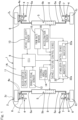
- FIG. 1 A first embodiment of the present invention will be described in connection with Figs. 1 to 4A and 4B .
- This embodiment pertains to example roll control for use in a scenario in which a vehicle 1 is equipped with active stabilizers 5 for front and rear wheels as an actuator that generates a roll moment to counteract roll.
- This vehicle 1 has a vehicle body 1A that is equipped with front and rear suspension devices 4 that provide a support to wheels 2 in the form of front left and right wheels 2f and wheels 2 in the form of rear left and right wheels 2r, respectively, and that is also provided with the active stabilizers 5 each serving as a roll stiffness varying mechanism for a respective set of the front wheels 2f and rear wheels 2r.
- front and rear suspension devices 4 that provide a support to wheels 2 in the form of front left and right wheels 2f and wheels 2 in the form of rear left and right wheels 2r, respectively, and that is also provided with the active stabilizers 5 each serving as a roll stiffness varying mechanism for a respective set of the front wheels 2f and rear wheels 2r.
- Each of the front and rear suspension devices 4 includes a shock absorber 7, as well as upper and lower suspension arms 4a above and below its constituent members, with a knuckle 6 being coupled through the upper and lower suspension arms 4a to the vehicle body 1A and supporting each wheel 2 in such a way that the steering angle for that wheel 2 is variable.
- the upper and lower suspension arms 4a are each swingably supported at a support point on a vehicle body-side end thereof, such that the wheel 2 makes upward and downward strokes in response to the swings of these upper and lower suspension arms 4a.
- a suspension device 4 Positioned between the lower suspension arm 4a and the vehicle body 1A is the shock absorber 7 formed of a spring and a damper, with the shock absorber 7 supporting the vehicle body 1A in an elastically and vertically movable manner while, on the other hand, damping strokes in a vertical direction.
- a suspension device 4 is sometimes simply referred to as a suspension 4.
- Each of the active stabilizers 5 is formed of left and right stabilizer members 5a made of, for example, a torsion bar and a stabilizer actuator segment 5b coupling these in a mutually twistable fashion.
- the stabilizer actuator segment 5b is a rotary actuator formed of an electric motor 8 as a drive source and a speed reducer (not shown) that reduces the speed of the output from this electric motor 8 so that an output shaft thereof rotates at a reduced speed.
- Propulsion for the vehicle 1 is provided by driving at least one set of the left and right wheels 2 in the form of the front wheels 2f or the left and right wheels 2 in the form of the rear wheels 2r by means of a propulsion drive source (not shown) such as, for example, an engine or a motor.
- the propulsion drive source is controlled according to an input from a driver, through a main ECU 9 that manages the basic operations of the vehicle 1.
- the main ECU 9 is also called a VCU and is made of a computer, etc.
- an accelerator pedal sensor 11 that senses an input of the driver to an accelerator pedal
- a brake pedal sensor 12 that senses an input to a brake pedal
- a vehicle velocity sensor 13 that senses a vehicle velocity
- a steering angle sensor 14 that senses a steering angle
- a yaw rate sensor 15 that senses a yaw rate
- an acceleration sensor 16 that senses the acceleration of the vehicle 1
- a vehicle posture control device 21 for implementing roll control and a stabilizer control device 22 for controlling the active stabilizers 5 are equipped.
- the stabilizer control device 22 includes two inverters 22a, each of which controls the electric motor 8 of the respective active stabilizers 5 on the front and the rear.
- An inverter 22a is formed of a power circuitry unit that converts the DC power from a battery to an AC power for the purpose of driving said motor and a driver circuitry unit that regulates this power circuitry unit.
- the outputs from the accelerator pedal sensor 11 and the brake pedal sensor 12 are input to the ECU 9 where they are converted to an accelerator command value and a brake command value to perform control of the propulsion drive source and a brake.
- the accelerator command value and the brake command value are, in turn, input to the vehicle posture control device 21.
- the vehicle velocity is also input through the ECU 9 to the vehicle posture control device 21.
- the steering angle sensor 14, the yaw rate sensor 15, and the acceleration sensor 16 respectively output steering angle information, a real yaw rate, and a real acceleration that are also input to the vehicle posture control device 21.
- Fig. 2 shows a block diagram of the vehicle posture control device 21.
- the vehicle posture control device 21 includes a sideslip angular velocity estimation unit 23, a roll moment calculator 24, and an actuator controller 25 that generates a command value to be output to the stabilizer control device 22.
- the actuator controller 25 includes a front and rear wheels roll moment calculator 26 and a command transformer 27.
- the sideslip angular velocity estimation unit 23 estimates a sideslip angular velocity according to a defined rule by using various values that are input thereto.
- a nonlinear tire model is used as the defined rule to estimate the sideslip angular velocity
- formulae (50) and (51) as discussed later are utilized.
- the roll moment calculator 24 calculates, according to a defined rule, a roll moment command value M ⁇ to control the active stabilizers 5 which represent the actuator that generates in the vehicle 1 a roll moment for counteracting roll, such that a roll motion is generated in conjunction with a yaw motion in the vehicle 1 during turning thereof. More specifically, the roll moment calculator 24 uses an estimate of the sideslip angular velocity, the vehicle velocity, and the real yaw rate to calculate a roll moment required for roll control by employing formula (5) as discussed later and output the same in the form of a roll moment command value M ⁇ .
- the front and rear wheels roll moment calculator 26 determines the allocation of the roll moment command value M ⁇ between the front and rear wheels.
- the determined allocation is output in the form of a front wheels roll moment command value M ⁇ f to be generated by an active stabilizer 5 for the front wheels 2f and a rear wheels roll moment command value M ⁇ r to be generated by an active stabilizer 5 for the rear wheels 2r.
- the front wheels roll moment command value M ⁇ f and the rear wheels roll moment command value M ⁇ r that are output are transformed by the command transformer 27 into values compatible to be inputs that the stabilizer control device 22 can handle - for example, a motor command torque - for output to the stabilizer control device 22. Note that, if the stabilizer control device 22 is configured to be able to handle a roll moment command value as an input thereto, the command transformer 27 is not required.
- the stabilizer control device 22 controls the active stabilizers 5 for the front wheels 2 f and the rear wheels 2 r , according to the front wheels roll moment command value M ⁇ f and the rear wheels roll moment command value M ⁇ r that are output from the vehicle posture control device 21, or according to those commands after having been transformed by the command transformer 27.
- the generation of a yaw rate and the appearance of a roll angle are coordinated so as to be in conjunction with each other in the vehicle 1 during the turning thereof, thereby narrowing the time gap therebetween as well.
- a roll motion can be coordinated so as to be in conjunction with a yaw motion which is a rotational motion of the vehicle 1, thereby imparting to a driver of the vehicle 1 a feeling of cohesiveness in the motion of the vehicle and therefore enhancing the maneuverability thereof.
- the followings are general formulae for a two-wheel model intended to only describe a translation motion, in a lateral direction, and a rotational motion, about a vertical axis, of the vehicle 1.
- the formulae (1) and (2) describe the relationship between a sideslip angle ⁇ and a yaw rate r of the vehicle, which appear in the vehicle during turning thereof.
- m is a vehicle mass
- V is a vehicle velocity
- ⁇ " ⁇ " (which is called a dot beta) is a sideslip angular velocity of the vehicle
- Y f is a cornering force acting on a front wheel (i.e., a lateral force to a front wheel)
- Y r is a cornering force acting on a rear wheel (i.e., a lateral force to a rear wheel)
- r" ⁇ " is a yaw angle acceleration
- l f is a distance between the point of center of gravity of the vehicle and a vehicle axle for the front wheels
- l r is a distance between the point of center of gravity of the vehicle and a vehicle axle for the rear wheels
- I is a yaw moment of inertia of the vehicle.
- Formula (3) shows that a lateral acceleration a y is composed of a lateral acceleration resulting from the sideslip angular velocity ⁇ " ⁇ " of the vehicle and a lateral acceleration resulting from the yaw rate r. It can be seen that, in a transient state during turning - as opposed to steady turning during which the sideslip angular velocity ⁇ " ⁇ " of the vehicle becomes zero - the lateral acceleration a y is shifted by the lateral acceleration V ⁇ " ⁇ " resulting from the sideslip angular velocity ⁇ " ⁇ ” of the vehicle. That is, the lateral acceleration a y is shifted its phase, in relation to the yaw rate r by an amount corresponding to the sideslip angular velocity ⁇ " ⁇ " of the vehicle.
- the two-wheel model is extended on the basis of the idea that the lateral acceleration a y acts on the center of gravity of the vehicle, thereby causing a roll angle ⁇ to appear in the vehicle.
- the roll angle ⁇ appears according to formula (4) whereby h s is a distance between the point of center of gravity of the vehicle and the axis of roll, K ⁇ is a roll stiffness, C ⁇ is a roll damping coefficient, and I ⁇ is a roll moment of inertia.
- Formula (4) shows that the roll angle ⁇ appears with a delay in relation to the lateral acceleration a y (or the roll moment mh s a y ) due to the damping characteristics of suspensions and a roll moment of inertia of the vehicle.
- fig. 3 depicts various parameters for a particular instance of a single lane change in which a lane change shifting from a lane being travelled to another lane is performed once during a high-speed travel regime.
- the yaw rate r appears in response to steering, while the lateral acceleration a y occurs later than the yaw rate r due to the effect of the sideslip angular velocity ⁇ " ⁇ ", thereby leading to the further delayed appearance of the roll angle ⁇ .
- This delay of the roll motion relative to the yaw motion widens with an increase in the vehicle velocity.
- This embodiment is characterized by generating a roll moment through the active stabilizers 5 equipped to the vehicle 1 such that a yaw motion and a roll motion are generated in a unified manner to coordinate the yaw motion and the roll motion in conjunction with each other and shorten the delay that occurs between the yaw motion and the roll motion as well.
- a roll moment which cancels out a roll moment resulting from the lateral acceleration a y during turning and which provides a roll moment resulting from the yaw motion may be imparted to the vehicle body as the roll moment command value M ⁇ .
- the roll moment generated upon imparting a yaw motion to the vehicle body can be selected to be a value with which a delay resulting from the damping of suspensions, etc. has been corrected.
- the roll moment calculator 24 performs a calculation according to formula (5) and outputs the roll moment command value M ⁇ as the calculation result.
- the first term on the right side of formula (5) is a term for cancelling out a roll motion resulting from the sideslip angular velocity ⁇ " ⁇ ", while the second term on the right side thereof is for compensating for a delay resulting from the damping of suspensions, etc.
- the first term is a term for allowing only a roll moment resulting from a yaw rate to be applied to the vehicle such that a yaw motion (i.e., the yaw rate) and a roll motion (i.e., a roll angle) are coordinated to be in conjunction with each other
- the second term is a term for compensating for phase delay in a roll moment resulting from the yaw rate.
- a yaw motion i.e., a yaw rate
- a roll motion i.e., a roll angle
- a delay of a roll motion which is relative to a yaw motion and caused by suspensions is shortened, thereby inducing a feeling of further cohesiveness in rotational motions of the vehicle. Since the roll motion M ⁇ can be calculated from the sideslip angular velocity ⁇ " ⁇ ", the yaw rate r, and the vehicle velocity V as they are being generated in the vehicle during turning thereof, there is no need to set a target value for the roll angle ⁇ or the roll angular velocity in advance.
- Fig. 4B depicts the behavior of the vehicle in an instance where the roll moment M ⁇ according to formula (B) is generated by an actuator mounted in the vehicle.
- the roll moment calculator 24 ( Fig. 2 ) performs a calculation according to formula (B) and outputs the roll moment command value M ⁇ as the calculation result.
- fig. 4B pertains to an instance in which a single lane change is performed during a high-speed travel regime.
- the roll moment M ⁇ causes the roll angle ⁇ to appear in conjunction with the yaw rate r in the vehicle.
- the roll angle appears later than the yaw rate due to the damping of suspensions, etc.
- the roll angle ⁇ appears earlier than the lateral acceleration a y . In this way, a feeling of cohesiveness is achieved in rotational motions (i.e., a yaw motion and a roll motion) of the vehicle, thereby enhancing the maneuverability thereof.
- Fig. 4A depicts the behavior of the vehicle in an instance where the roll moment M ⁇ according to formula (5) is generated by an actuator mounted in the vehicle. Just like the one in Fig. 3 , this pertains to an instance in which a single lane change is performed during a high-speed travel regime.
- the roll moment M ⁇ causes the roll angle ⁇ to appear in the vehicle with a phase closer to that of the yaw rate r. In this way, a feeling of cohesiveness is achieved in rotational motions (i.e., a yaw motion and a roll motion) of the vehicle, thereby enhancing the maneuverability thereof.
- the roll angle ⁇ appears earlier than the lateral acceleration a y , thereby allowing a driver to immediately feel the change in the yaw rate r that occurs in the vehicle by perceiving the change in the roll angle ⁇ .
- An actual vehicle test has confirmed that the maneuverability of the vehicle 1 is enhanced thereby.
- a vehicle that had been tailored so as to exhibit an oversteering tendency by adjusting the tire grip forces of its rear wheels 2 r to be lower than those of its front wheels 2 f was used to conduct slalom driving. Without the use of control according to this embodiment, the rear wheels would start slipping in response to an increase in the lateral acceleration, before the generation of roll takes place (see Fig. 3 ).
- the driver could prepare for early steering correction to be performed while at the same time checking whether the rear wheels have actually started slipping, and therefore was able to mitigate the occurrence of a large disturbance in the behavior of the vehicle.
- Figs. 5 to 8 depict another embodiment of the present invention.
- the same features as those of the first embodiment will apply to each of the embodiments that are illustrated below, except for those that are particularly discussed.
- Figs. 5 to 8 refers to an example in which active suspensions 4A are provided in place of the active stabilizers 5 in the first embodiment ( Fig. 1 ), as an actuator that generates a roll moment and a pitch moment in the vehicle 1 for the purpose of counteracting roll and for pitch control.
- Each of the active suspensions 4A is formed of a suspension 4 and a support portion vertical force varying mechanism 7A.
- Each of the active suspensions 4A used in this embodiment includes suspension arms 4a, with a knuckle 6 being coupled through these upper and lower suspension arms 4a to the vehicle body 1A and supporting a respective wheel 2 in such a way that the steering angle for that wheel 2 is variable.
- the upper and lower suspension arms 4a are each swingably supported at a support point on a vehicle body-side end thereof, such that the wheel 2 makes upward and downward strokes in response to the swings of these upper and lower suspension arms 4a.
- a shock absorber (not shown) formed of a spring and a damper.
- the support portion vertical force varying mechanism 7A is arranged so as to change the support position of this shock absorber up and down or so as to be able to vary a vertical force acting on said support position.
- the support portion vertical force varying mechanism 7A is made of, for example, a drive source such as hydraulics or a motor, and a linear motion device (both not shown). Stabilizers 5A are also provided.
- a suspension control device 31 for controlling the active suspensions 4A is provided.
- Fig. 6 shows a block diagram of a vehicle posture control device 21A, in accordance with this embodiment.
- this embodiment differs from the block diagram of the aforementioned embodiment of Fig. 2 by the addition of a pitch moment calculator 33 and by being equipped with an actuator controller 34A for counteracting roll and for pitch control.
- a roll moment calculator 24 has the same configuration as that discussed in connection with Fig. 2 .
- the actuator controller 34A calculates a command value to control the support portion vertical force varying mechanism 7A of each active suspension 4A, according to a roll moment command value calculated by the roll moment calculator 24 and a pitch moment command value calculated by the pitch moment calculator 33, and outputs the same to the suspension control device 31.
- the suspension control device 31 controls the support portion vertical force varying mechanism 7A of each active suspension 4A ( Fig. 5 ), according to a command value that is input thereto.
- the pitch moment calculator 33 may calculate the pitch moment command value Me, on the basis of at least a yaw rate and a vehicle velocity of the vehicle 1. It is also preferred that the pitch moment calculator 33 provides the pitch moment command value M ⁇ as a value that compensates for a delay spanning between the generation of a pitch moment and the occurrence of change of a pitch angle in the vehicle 1 and caused by characteristics such as the damping of springs or dampers that the active suspensions 4A ( Fig. 5 ) have.
- a pitch motion is coordinated so as to be in conjunction with a yaw motion which is a rotational motion of the vehicle 1. Consequently, a driver of the vehicle 1 experiences a feeling of cohesiveness in the motion of the vehicle 1, with the ride comfort and the maneuverability thereof being thereby improved.
- This embodiment causes the active suspensions 4A, each of which is an actuator equipped to the vehicle 1, to generate a pitch moment such that a yaw motion and a pitch motion are generated in conjunction with each other and in a unified manner.
- Formula (6) describes a pitch moment M ⁇ that acts on the point G of center of gravity of the vehicle 1.
- the pitch moment M ⁇ is proportional to the magnitude of the lateral acceleration Vr resulting from a yaw rate r, with a delay due to the damping characteristics of suspensions 4, etc. having been compensated for. Only the first-order delay may be compensated for, though the second-order delay is shown to be done so as well in formula (6).
- the phase delay compensation can be performed only with respect to the first-order delay to do away with higher-order derivative calculations, thereby reducing a calculation load and keeping small the impacts of possible noise contained in the yaw rate signal.
- the size of the control gain k is a value determined by a simulation or an experiment and is set to a value smaller than 1 (for example, no more than 0.1). Also, the direction of the pitch moment changes with whether the control gain k is positive or negative. With a positive gain, the pitch moment puts the vehicle in a forward diving posture, whereas with a negative gain, the pitch moment puts the vehicle 1 in a rearward squatting posture. Our previous research shows that it is preferred to generate a forward diving pitch in a vehicle during turning thereof, to improve the maneuverability thereof. This is described in detail in Non-patent Document 1.
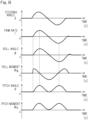
- Fig. 8 depicts the behavior of the vehicle in an instance where the pitch moment M ⁇ according to formula (6) is generated by an actuator mounted in the vehicle and is additionally applied to the example of Fig. 4A .
- the pitch moment M ⁇ causes the vehicle 1 to have a forward diving pitch commensurate with an increase in the yaw rate ⁇ .
- the pitch moment calculator 33 may be configured such that a larger pitch angle in the direction of forward diving is generated in the vehicle 1 ( Fig. 5 ) in response to a greater absolute value of the yaw rate.
- each of the active suspensions 4A which is an actuator equipped to the vehicle to generate the abovementioned roll moment M ⁇ and pitch moment Me, be configured to apply a force in a vertical direction to the sprung mass of the vehicle 1 through the shock absorber, which is a constituent member of the suspension device 4.
- the constituent members of the suspension device 4 are designed to support all of the forces that act on tires and that the vehicle body 1A mounted thereon also comes with the rigidity and strength expected therefor, additional reinforcements, etc. can be omitted.
- a typical suspension 4 is positioned in each of the four corners of a vehicle, just as in this embodiment. Accordingly, each vertical force used to produce the roll moment M ⁇ and pitch moment M ⁇ can be kept small.
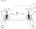
- a vertical force produced in a suspension by means of an actuator is denoted as FS i .
- a vertical force FS i acts through a spring and a damper bearing the sprung mass of the vehicle.
- These spring and damper are constituent members of each suspension 4.
- the symbol i denotes the positions of suspensions in a four-wheeled vehicle, with 1 indicating a front left wheel, 2 indicating a front right wheel, 3 indicating a rear left wheel, and 4 indicating a rear right wheel. This also applies to the embodiments that are mentioned later.
- the spring and the damper are arranged on the same axis.
- the distance in a longitudinal direction between the point G of center of gravity of the vehicle and the position of a point where the spring and the damper at a front wheel 2 f bear the sprung mass of the vehicle 1 (i.e., bearing point) is indicated as ls f
- the distance in the longitudinal direction between the point G of center of gravity of the vehicle and the position of a bearing point of the spring and the damper at a rear wheel 2 r is indicated as ls r
- the distance between the bearing points of the springs and the dampers of left and right suspensions 4 for front wheels 2 f is indicated as ds f
- the distance between the bearing points of the springs and the dampers of left and right suspensions 4 for rear wheels 2 r is indicated as ds r .
- Figs. 9 to 11 depict yet another embodiment of the present invention.
- in-wheel motors (IWMs) 30 are equipped to four wheels which are front and rear sets of left and right wheels in place of the active stabilizers 5 in the first embodiment ( Fig. 1 ), as an actuator that generates a roll moment, etc. in a vehicle 1 to which this vehicle posture control device 21B is applied, for the purpose of counteracting roll and for pitch control.
- Each of the in-wheel motors 30 is formed of a motor and a speed reducer or is formed of a motor alone, with an entirety or a large part thereof being arranged inside a wheel 2.
- the in-wheel motors 30 which are each a drive source for providing propulsion drive and braking can generate in the vehicle 1 a roll moment for counteracting roll and can also generate a pitch moment for pitch control, through the regulation of the relationship in braking/driving force (i.e., longitudinal force) among the four wheels.
- a motor control device 41 for controlling the in-wheel motors 30 is equipped.
- the motor control device 41 implements control of the in-wheel motors 30 for roll control and pitch control under the command of the vehicle posture control device 21B, in addition to executing normal travel and braking control that is commensurate with an accelerator command value and a brake command value.
- the motor control device 41 includes inverters 42 that respectively control an in-wheel motor 30 of each wheel 2.
- Each of the inverters 42 is formed of a large power unit that converts the DC power from a battery to an AC power and a controller unit that regulates the output therefrom.
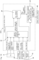
- Fig. 10 shows a block diagram of the vehicle posture control device 21B.
- this embodiment differs from the block diagram of the first embodiment of Fig. 2 by the addition of a pitch moment calculator 33 and by being equipped with a longitudinal force command value calculator 34 as an actuator controller configured both for counteracting roll and for pitch control.
- the functions of a sideslip angular velocity estimation unit 23 and a roll moment calculator 24 are identical to those described in connection with Fig. 2 .
- the pitch moment calculator 33 has the same function as that described in connection with Fig. 6 and calculates the pitch moment command value M ⁇ to be generated in the vehicle 1 according to formula (6) mentioned above, from at least a vehicle velocity and a real yaw rate.
- the longitudinal forces produced in roll control by means of the roll moment calculator 24 may be such that the total value of longitudinal forces to front and rear right wheels is an approximately equal value to the total value of longitudinal forces to front and rear left wheels.
- the longitudinal forces produced in roll control or pitch control by means of the roll moment calculator 24 or the pitch moment calculator 33 may be such that the total value of longitudinal forces to front and rear right wheels is an approximately equal value to the total value of longitudinal forces to front and rear left wheels.
- the pitch moment calculator 33 may be configured such that a larger pitch angle in the direction of forward diving is generated in the vehicle 1 in response to a greater absolute value of a yaw rate.
- the longitudinal force command value calculator 34 calculates the longitudinal forces FX 1 according to formulae (29) to (32) that are discussed below, from the roll moment command value M ⁇ and the pitch moment command value M ⁇ that are input thereto.
- the vehicle posture control device 21B adds, to the longitudinal forces FX 1 calculated according to formulae (29) to (32) that are discussed below, longitudinal forces commensurate with an accelerator command value and a brake command value and outputs the resultant as a longitudinal force command value.
- the motor control device 41 regulates the motor torques of the in-wheel motors 30 in accordance with longitudinal force command values that are output from the vehicle posture control device 21B.
- an in-wheel motor 30 which provides a longitudinal force that acts on a tire contact surface and thereby creates a larger anti-dive angle or anti-squat angle, a greater vertical force can be produced with a given braking/driving force.
- the anti-dive angle or the anti-squat angle is smaller as compared to that for a vehicle equipped with in-wheel motors 30, although it is still possible to produce vertical forces in a similar mechanism.
- a vertical force FS i is produced through a suspension 4 in response to a longitudinal force FX i in the following ways.
- the braking force acting on a front wheel 2 f and the driving force acting on a rear wheel 2 r among the longitudinal forces FX i are denoted as FB f and FD r , to illustrate the relationship between the orientations of longitudinal forces and vertical forces.
- the vertical force produced as a result of FB f mentioned above and the vertical force produced as a result of FD r mentioned above are shown as FB f tan ⁇ f and FD r tan ⁇ r .
- the longitudinal forces FX i required to generate the roll moment M ⁇ and the pitch moment M ⁇ can be calculated as follows.
- the longitudinal force command value calculator 34 of Fig. 10 performs calculations according to formulae (29) to (32) and outputs the calculation result according to each formula as a longitudinal force command value: [Math 16]
- FX 1 ⁇ M ⁇ ds f tan ⁇ f + ds r tan ⁇ r + M ⁇ 2 ls f tan ⁇ f ⁇ ls r tan ⁇ r
- FX 2 M ⁇ ds f tan ⁇ f + ds r tan ⁇ r + M ⁇ 2 ls f tan ⁇ f ⁇ ls r tan ⁇ r
- FX 3 M ⁇ ds f tan ⁇ f + ds r tan ⁇ r ⁇ M ⁇ 2 ls f tan ⁇ f ⁇
- Formula (35) represents a condition of the vehicle required to produce a heave in an upward direction along with a forward diving pitch in the vehicle during turning thereof: ls f tan ⁇ f ⁇ ls r tan ⁇ r ⁇ 0
- Figs. 12 and 13 depict yet another embodiment of the present invention.
- This embodiment pertains to an example in which roll is controlled by using brakes 35 equipped to four wheels 2 that are on the front and the rear and for the left and the right as shown in Fig. 12 , in place of the active stabilizers 5 of Fig. 1 or the in-wheel motors 30 of Fig. 9 , as an actuator that generates a roll moment in the vehicle 1 for the purpose of counteracting roll.
- Each of the brakes 35 is a friction brake such as an electric brake or a hydraulic brake.
- a brake control device 46 for controlling the brakes for the four wheels is also equipped.
- Fig. 13 shows a block diagram of a vehicle posture control device 21C, in accordance with this embodiment.
- the pitch moment calculator 33 in the block diagram of Fig. 6 or 10 is not present.
- the functions of a sideslip angular velocity estimation unit 23 and a roll moment calculator 24 are identical to those in the example of Fig. 2 .
- a longitudinal force command value calculator 47 is equipped as an actuator controller for counteracting roll.
- the longitudinal force command value calculator 47 calculates the longitudinal forces FX i according to formulae (40) to (47) as discussed below, from a roll moment command value that is input thereto.
- the vehicle posture control device 21C adds, to the longitudinal forces FX i calculated according to formulae (29) to (32) that are discussed below, longitudinal forces (i.e., braking forces) commensurate with a brake command value and outputs the resultant as a longitudinal force command value.
- the brake control device 46 regulates each of the brakes 35 in accordance with the longitudinal force command value that is output from the vehicle posture control device 21C.
- the existing brake system refers to a system in which the output from a brake pedal sensor that senses an input to a brake pedal is, in turn, input to an ECU 9 that transforms the same to a brake command value for execution of brake control. Since it is a braking force that is produced by the brake system, a condition for the longitudinal forces FX i will be defined as follows: FX i ⁇ 0
- the longitudinal force command value calculator 47 which is the aforementioned actuator controller, outputs longitudinal force command values that apply, for example, approximately equal braking forces to diagonally opposite wheels 2 of the vehicle 1.
- the roll moment M ⁇ to be generated is calculated according to formula (5), from the sideslip angular velocity ⁇ " ⁇ " and the yaw rate r as they are being generated in the vehicle 1.
- the yaw rate r can be measured with a yaw rate sensor, which is mounted in a vehicle as a constituent component of a vehicle electronic stability control device.
- a yaw rate sensor which is mounted in a vehicle as a constituent component of a vehicle electronic stability control device.
- the sideslip angular velocity estimation unit 23 may estimate a sideslip angular velocity ⁇ " ⁇ " from a steering angle ⁇ by employing a vehicle model or may estimate the same from a yaw rate r measured with the yaw rate sensor 15 mounted in the vehicle.
- G ⁇ ⁇ 0 represents a sideslip angle gain constant
- T ⁇ represents a sideslip angle time constant
- ⁇ represents a damping ratio of the yaw response of the vehicle to steering
- ⁇ n represents a natural frequency of the yaw response of the vehicle to steering.
- Steering angle information obtained by a calculation involving an angle of rotation of, for example, a gear, the amount of displacement of a rack, etc. that is output from a sensor associated with a steering rack can be used as the steering angle ⁇ , in addition to a value calculated from the output from the steering angle sensor 14 provided in a steering unit.
- a sideslip angular velocity ⁇ " ⁇ " can be calculated from a lateral acceleration a y and a yaw rate r that are measured with sensors mounted in the vehicle. Yet, on a cant road where the lateral acceleration a y changes with the slope thereof, an error could occur in the estimated sideslip angular velocity ⁇ " ⁇ ". Also, since the model used in both of formulae (48) and (49) is a linear tire model, there may be a larger error under conditions where the lateral force to a tire may saturate. Further, in situations where a longitudinal acceleration is involved, a larger error may likewise occur. As an approach to reducing such errors, a method that uses a nonlinear tire model to estimate a sideslip angular velocity ⁇ " ⁇ " is proposed in the art (see Non-patent document 3).
- the suffix T represents either a front wheel (f) or a rear wheel (r)
- K T indicates the cornering power of a tire
- ⁇ T indicates a sideslip angle at the position of a front wheel or a rear wheel
- ⁇ indicates a coefficient of road friction
- W T indicates a vertical load on a tire
- X T indicates a longitudinal force to a tire.
- a sideslip angular velocity ⁇ " ⁇ " is estimated according to formula (51).
- the nonlinear tire model in formula (50) takes into account the saturation of a lateral force Y T to a tire as well as a vertical load on a tire, the accuracy of the estimate of a lateral force Y T to a tire is improved.
- the use of formula (51) allows for the accurate estimation of a sideslip angular velocity ⁇ " ⁇ " from a yaw rate r measured with the yaw rate sensor 15 mounted in the vehicle.
Landscapes
- Engineering & Computer Science (AREA)
- Mechanical Engineering (AREA)
- Transportation (AREA)
- Automation & Control Theory (AREA)
- Chemical & Material Sciences (AREA)
- Combustion & Propulsion (AREA)
- Physics & Mathematics (AREA)
- Mathematical Physics (AREA)
- Vehicle Body Suspensions (AREA)
Abstract
Description
- This application is based on and claims Convention priority to
Japanese patent applications No. 2020-173949, filed October 15, 2020 No. 2021-034820, filed March 4, 2021 - The present invention relates to a vehicle motion control device for controlling the roll motion and, optionally, the pitch motion of a vehicle during turning thereof, and also relates to such a vehicle.
- Techniques that control the roll of a vehicle generated during turning thereof to improve the ride comfort or maneuverability of the vehicle can be found in, for example,
Patent Document 1 andPatent Document 2 cited below. - The techniques in
Patent Document 1 are directed to varying the damping forces of dampers in suspensions so as to control the roll angle resulting from a lateral acceleration or the pitch angle resulting from a longitudinal acceleration. Roll angle control or pitch angle control with enhanced responsiveness can be achieved by varying the damping forces of the dampers on the basis of a derivative of a lateral acceleration or a derivative of a longitudinal acceleration. - The techniques in
Patent Document 2 are directed to controlling the roll angle of a vehicle equipped with an active stabilizer or dampers with a variable damping force. By estimating the roll angle of a vehicle body as it is being generated, from a vehicle velocity and a steering angle that are sensed, and varying the damping characteristics or spring characteristics of suspensions on the basis of its deviation from a target roll angle, roll resulting in response to a lateral acceleration can be counteracted in such a way to narrow or keep at a constant the time gap between the occurrence of the lateral acceleration and the occurrence of roll. -
- [Patent Document 1]
JP Laid-open Patent Publication No. 2006-069527 - [Patent Document 2]
JP Laid-open Patent Publication No. 2007-106257 -
- [Non-patent Document 1] M. Yamakado, R. Tanaka, Y. Kano, M. Abe, Y. Suzuki, S. Kosaka, W. Cheng. "Influence of Vehicle Body Motion on the Effects of G-Vectoring Control." (2017 JSAE Spring Convention) Proceedings
- [Non-patent Document 2] T. Nagashima, Y. Nakai, Y. Suzuki, Y. Nakano, M. Yamakado, Y. Kano, M. Abe. "Influence of Heave Motion by Driving/ Braking Force Control on the Steering Characteristic." (2019 JSAE Fall Convention) Proceedings
- [Non-patent Document 3] M. Abe, et al. "Estimation of Vehicle Side-Slip Angle for DYC by Using On-Board-Tire-Model." AVEC '98(1998.9)
- Typically, the timing when a yaw rate appears in a vehicle in response to a steering input from a driver, as well as the timing when a lateral acceleration occurs, vary with a vehicle velocity. For example, during a low-speed travel regime, a lateral acceleration occurs in the vehicle in response to a steering input from a driver, and slightly later, a yaw rate appears. Roll, in turn, is generated with a delay from the yaw rate, due to a moment of inertia of the sprung mass and the damping forces of suspensions acting to delay the roll generation with respect to the lateral acceleration. During a high-speed travel regime, on the other hand, a yaw rate appears in a vehicle in response to a steering input from a driver, and later, a lateral acceleration occurs with a delay. Roll, in turn, is generated with a further delay from the lateral acceleration due to the impacts of a moment of inertia of the sprung mass and the damping forces of suspensions.
- In both of
Patent Documents Patent Document 1 is performed in relation to a longitudinal acceleration without taking a yaw motion during turning into consideration. Thus, a yaw motion and a pitch motion are not coordinated during turning and, instead, are generated with different timings. A driver experiences little feeling of cohesiveness in the motion of the vehicle. - An object of the present invention is to provide a vehicle posture control device, which can impart to a driver of a vehicle a feeling of cohesiveness in the motion of the vehicle during turning thereof and enhances the maneuverability thereof, and such a vehicle.
- Now, the present invention will be described below with reference to the symbols in embodiments for the sake of discussion, namely, in order to facilitate the understanding of the invention.
- A vehicle posture control device according to the present invention is configured to be installed in a
vehicle 1 provided with an actuator (5, 4A, 30, 35) configured to generate a roll moment. The device includes: aroll moment calculator 24 configured to calculate a roll moment command value Mφ to control the actuator (5, 4A, 30, 35) such that a roll motion is generated in conjunction with a yaw motion in thevehicle 1 during turning thereof, with theroll moment calculator 24 being configured to calculate the roll moment command value Mφ for output, on the basis of a sideslip angular velocity and a vehicle velocity of thevehicle 1; and anactuator controller - Except for the speed of the vehicle, a value obtained by multiplying the speed of the vehicle with a certain coefficient, or a parameter proportionate to the speed of the vehicle - for example, a vehicle wheel velocity - may be used as said vehicle velocity. The coefficient is determined by at least one of a test or a simulation.
- According to this configuration, the
roll moment calculator 24 calculates, in thevehicle 1 during turning thereof, the roll moment command value Mφ to control the actuator such that a yaw rate and a roll angle are generated in thevehicle 1 during turning thereof in conjunction with each other, and uses theactuator controller - In the present invention, the term "yaw rate" is synonymous with the term "yaw motion," whereas the term "roll angle" is synonymous with the term "roll motion."
- In this way, a roll motion can be coordinated so as to be in conjunction with a yaw motion, thereby imparting to a driver of the vehicle 1 a feeling of cohesiveness in the motion of the
vehicle 1 and enhancing the maneuverability thereof. - Since the
roll moment calculator 24 is configured to calculate the roll moment command value Mφ for output, on the basis of a sideslip angular velocity and a vehicle velocity of thevehicle 1, the calculation of the roll moment command value Mφ can be easily executed. For instance, a calculation formula or a map defining the relationship among the sideslip angular velocity, the vehicle velocity, and the roll moment command value Mφ can be provided to calculate the roll moment command value Mφ according to the definitions therein. - In the present invention, the
roll moment calculator 24 may include a formula according to which the roll moment command value Mφ is calculated and which includes a term that compensates for phase delay of a roll motion resulting from a yaw rate. - In the context of this configuration, a roll moment that not only cancels out a roll moment resulting from a sideslip angular velocity but also compensates for a delay caused by the damping of a
suspension 4, etc. is generated in thevehicle 1, with the delay of a roll motion relative to a yaw motion being shortened as a result thereof. A feeling of further cohesiveness is achieved by rotational motions (i.e., the yaw motion and the roll motion) of thevehicle 1, thereby further enhancing the maneuverability thereof. - In the present invention, the
vehicle 1 may be further provided with an actuator configured to generate a pitch moment during turning thereof, and the vehicle posture control device may further include: apitch moment calculator 33 configured to calculate a pitch moment command value Mθ in accordance with said yaw rate, with thepitch moment calculator 33 being configured to calculate the pitch moment command value Me, on the basis of at least the yaw rate and the vehicle velocity of thevehicle 1; whereinpitch moment calculator 33 controls the actuator by using the calculated pitch moment command value Me. - In the context of this configuration, not only are the generation of a yaw rate and the appearance of a roll angle coordinated so as to be in conjunction with each other in the
vehicle 1 during the turning thereof, thereby narrowing the time gap therebetween as well, but also a pitch angle commensurate with the size of the yaw rate is generated in thevehicle 1. In this way, a roll motion and a pitch motion can be coordinated so as to be in conjunction with a yaw motion, which is a rotational motion of thevehicle 1, thereby imparting to a driver of the vehicle 1 a feeling of further cohesiveness in the motion of the vehicle and therefore further enhancing the maneuverability thereof. - When additionally implementing pitch control in such a manner, the
pitch moment calculator 33 may be configured to provide the pitch moment command value Mθ as a value that compensates for a delay spanning between the generation of the pitch moment and the occurrence of change of a pitch angle in thevehicle 1 and caused by the characteristics of a suspension. - In the context of this configuration, a delay in the occurrence of change of a pitch angle in the
vehicle 1 is compensated for. Hence, a driver of thevehicle 1 can experience a feeling of further cohesiveness in the motion of thevehicle 1. Therefore, the maneuverability thereof is further enhanced. - In the present invention, the actuator configured to generate the roll moment may be a device mounted to a
suspension 4 and configured to apply a force in a vertical direction to thevehicle 1 through a constituent member of thesuspension 4 to generate the roll moment. - In this case, an existing actuator can be utilized, with no change in the design of a vehicle body being necessary. For instance, an
active stabilizer 5, anactive suspension 4A, an in-wheel motor 30, or abrake 35 can be used as the actuator. - In the present invention, when additionally implementing the pitch control, at least one of the actuator configured to generate the roll moment or the actuator configured to generate the pitch moment may be a device mounted to a
suspension 4 and configured to apply a force in a vertical direction to thevehicle 1 through a constituent member of thesuspension 4 to generate either one of the roll moment or the pitch moment. - In this case, too, an existing actuator can be utilized, with no change in the design of a vehicle body being necessary. An
active stabilizer 5, anactive suspension 4A, an in-wheel motor 30, abrake 35, etc. can be used as the actuator in this context. - In the present invention, the actuator configured to generate the roll moment may be a device capable of producing a longitudinal force to a tire and configured to apply a vertical force to the
vehicle 1 by cooperating with a link arrangement of a suspension with an anti-dive angle for thesuspension 4 at afront wheel 2f and an anti-squat angle at arear wheel 2r. - In the context of this configuration, a
brake 35 or an in wheel-motor 30 can be used as the actuator. - In the present invention, the actuator configured to generate the roll moment and the actuator configured to generate the pitch moment may be represented by a device capable of producing a longitudinal force to a tire and configured to apply a vertical force to the
vehicle 1 by cooperating with a link arrangement of a suspension with an anti-dive angle for thesuspension 4 at a front wheel and an anti-squat angle at a rear wheel. - In the context of this configuration, too, a
brake 35 or an in wheel-motor 30 can be used as the actuator. - In the present invention, the
pitch moment calculator 33 may be configured such that a larger pitch angle in the direction of forward diving is generated in thevehicle 1 in response to a greater absolute value of a yaw rate. - In this context, a forward diving pitch is more preferred.
- In the context of this configuration, the vehicle posture control device may be configured to be installed in a
vehicle 1 in which the magnitude of the product between the tangent of an anti-dive angle at afront wheel 2f and the distance in a longitudinal direction between the point G of center of gravity of the vehicle and a point of asuspension 4 at thefront wheel 2f at which a spring and a damper thereof bear the sprung mass of thevehicle 1 is smaller than the magnitude of the product between the tangent of an anti-dive angle at arear wheel 2r and the distance in the longitudinal direction between the point G of center of gravity of the vehicle and a point of asuspension 4 at therear wheel 2r at which a spring and a damper thereof bear the sprung mass of thevehicle 1. - In the context of this configuration, an upward heave can be produced when a forward diving pitch is generated.
- In the present invention, the
roll moment calculator 24 may be configured to estimate the sideslip angular velocity from steering angle information sensed by asteering angle sensor 14 equipped to the vehicle. The steering angle information represents either a steering angle or a signal corresponding to a steering angle. - In this way, the need for a sensor exclusively for a sideslip angular velocity can be obviated.
- In the present invention, the
roll moment calculator 24 may be configured to estimate the sideslip angular velocity from a yaw rate sensed by ayaw rate sensor 15 equipped to thevehicle 1. - In this way, the need for a sensor exclusively for a sideslip angular velocity can be obviated.
- In the present invention, the longitudinal force produced in roll control by means of the
roll moment calculator 24 may be such that the total value of longitudinal forces to front and rear right wheels is an approximately equal value to the total value of longitudinal forces to front and rear left wheels. - The term "approximately equal value" may allow for the presence of a difference between the total value of longitudinal forces to the front and rear right wheels and the total value of longitudinal forces to the front and rear left wheels to such an extent that the posture of the vehicle does not become unstable during the turning thereof. This difference is determined as appropriate, for example, by at least one of a test or a simulation.
- In this way, possible variation of a yaw rate as a result of the control can be kept small.
- In the present invention, the longitudinal force produced in roll control or pitch control by means of the
roll moment calculator 24 or thepitch moment calculator 33 may be such that the total value of longitudinal forces to front and rear right wheels is an approximately equal value to the total value of longitudinal forces to front and rear left wheels. - The term "approximately equal value" may allow for the presence of a difference between the total value of longitudinal forces to the front and rear right wheels and the total value of longitudinal forces to the front and rear left wheels to such an extent that the posture of the vehicle does not become unstable during the turning thereof. This difference is determined as appropriate, for example, by at least one of a test or a simulation.
- In this case, too, possible variation of a yaw rate as a result of the control can be kept small.
- In the present invention, the actuator controller (47) may be configured such that, when the actuator configured to generate the roll moment is a device (30, 35) that uses a braking force to generate the roll moment, approximately equal braking forces are applied to diagonally
opposite wheels 2 of thevehicle 1. - When roll control is performed through braking in this configuration, possible variation of a yaw rate as a result of the control can be kept small along with a minimum deceleration of the vehicle.
- A vehicle according to the present invention includes a vehicle posture control device according to one of the aforementioned configurations of the present invention.
- According to a vehicle having this configuration, the generation of a yaw rate and the appearance of a roll angle can be coordinated so as to be in conjunction with each other in the vehicle during the turning thereof, thereby narrowing the time gap therebetween as well, letting a driver of the vehicle experience a feeling of cohesiveness in the motion of the vehicle, and enhancing the maneuverability thereof, as has been discussed in regard to the vehicle posture control device according to the present invention.
- The present invention encompasses any combination of at least two features disclosed in the claims and/or the specification and/or the drawings. In particular, any combination of two or more of the appended claims should be equally construed as included within the scope of the present invention.
- The present invention will be more clearly understood from the following description of preferred embodiments thereof, when taken in conjunction with the accompanying drawings. However, the embodiments and the drawings are given only for the purpose of illustration and explanation, and are not to be taken as limiting the scope of the present invention in any way whatsoever, which scope is to be determined by the appended claims. In the accompanying drawings, like reference numerals are used to denote like or corresponding parts throughout the several views. In the figures,
-
Fig. 1 shows a block diagram illustrating a concept configuration of an automotive vehicle that is installed with a vehicle posture control device for use in a vehicle equipped with active stabilizers, in accordance with a first embodiment of the present invention; -
Fig. 2 shows a block diagram illustrating a concept configuration of the vehicle posture control device; -
Fig. 3 shows a chart illustrating the relationship among a yaw rate, a roll angle, and so on that occur in the vehicle when roll control is not implemented; -
Fig. 4A shows a chart illustrating the relationship among a yaw rate, a roll moment, and so on that occur in the vehicle when roll control is implemented; -
Fig. 4B shows a chart illustrating the relationship in an alternative variant among a yaw rate, a roll moment, and so on when the roll control is implemented; -
Fig. 5 shows a block diagram illustrating a concept configuration of an automotive vehicle that is installed with a vehicle posture control device for use in a vehicle equipped with active suspensions, in accordance with another embodiment of the present invention; -
Fig. 6 shows a block diagram illustrating a concept configuration of the vehicle posture control device; -
Fig. 7A shows a diagram of the vehicle as viewed from the front, illustrating how vertical forces produced in the vehicle may act; -
Fig. 7B shows a diagram of the vehicle as viewed from the rear, illustrating how vertical forces produced in the vehicle may act; -
Fig. 7C shows a diagram of the vehicle as viewed from a lateral side, illustrating how vertical forces produced in the vehicle may act; -
Fig. 8 shows a chart illustrating the relationship among a yaw rate, a roll moment, a pitch moment, and so on that occur in the vehicle when pitch control is implemented; -
Fig. 9 shows a block diagram illustrating a concept configuration of an automotive vehicle that is installed with a vehicle posture control device for use in a vehicle equipped with in-wheel motors, in accordance with yet another embodiment of the present invention; -
Fig. 10 shows a block diagram illustrating a concept configuration of the vehicle posture control device; -
Fig. 11 shows a diagram of the vehicle as viewed from a lateral side, illustrating how pitch control implemented with the vehicle posture control device may act; -
Fig. 12 shows a block diagram illustrating a concept configuration of an automotive vehicle that is installed with a vehicle posture control device for using a brake to implement posture control, in accordance with yet another embodiment of the present invention; and -
Fig. 13 shows a block diagram illustrating a concept configuration of the vehicle posture control device. - A first embodiment of the present invention will be described in connection with
Figs. 1 to 4A and4B . This embodiment pertains to example roll control for use in a scenario in which avehicle 1 is equipped withactive stabilizers 5 for front and rear wheels as an actuator that generates a roll moment to counteract roll. - This
vehicle 1 has avehicle body 1A that is equipped with front andrear suspension devices 4 that provide a support towheels 2 in the form of front left andright wheels 2f andwheels 2 in the form of rear left andright wheels 2r, respectively, and that is also provided with theactive stabilizers 5 each serving as a roll stiffness varying mechanism for a respective set of thefront wheels 2f andrear wheels 2r. - Each of the front and
rear suspension devices 4 includes ashock absorber 7, as well as upper andlower suspension arms 4a above and below its constituent members, with aknuckle 6 being coupled through the upper andlower suspension arms 4a to thevehicle body 1A and supporting eachwheel 2 in such a way that the steering angle for thatwheel 2 is variable. The upper andlower suspension arms 4a are each swingably supported at a support point on a vehicle body-side end thereof, such that thewheel 2 makes upward and downward strokes in response to the swings of these upper andlower suspension arms 4a. Positioned between thelower suspension arm 4a and thevehicle body 1A is theshock absorber 7 formed of a spring and a damper, with theshock absorber 7 supporting thevehicle body 1A in an elastically and vertically movable manner while, on the other hand, damping strokes in a vertical direction. Note that asuspension device 4 is sometimes simply referred to as asuspension 4. - Each of the
active stabilizers 5 is formed of left andright stabilizer members 5a made of, for example, a torsion bar and astabilizer actuator segment 5b coupling these in a mutually twistable fashion. By causing, through thestabilizer actuator segment 5b, the left andright stabilizer members 5a to be mutually twisted, the elastic force of a respectiveactive stabilizer 5 as a whole is varied in such a way to control the roll stiffness of thevehicle 1. By way of example, thestabilizer actuator segment 5b is a rotary actuator formed of anelectric motor 8 as a drive source and a speed reducer (not shown) that reduces the speed of the output from thiselectric motor 8 so that an output shaft thereof rotates at a reduced speed. - Propulsion for the
vehicle 1 is provided by driving at least one set of the left andright wheels 2 in the form of thefront wheels 2f or the left andright wheels 2 in the form of therear wheels 2r by means of a propulsion drive source (not shown) such as, for example, an engine or a motor. The propulsion drive source is controlled according to an input from a driver, through amain ECU 9 that manages the basic operations of thevehicle 1. Themain ECU 9 is also called a VCU and is made of a computer, etc. - As a class of sensors, an
accelerator pedal sensor 11 that senses an input of the driver to an accelerator pedal, abrake pedal sensor 12 that senses an input to a brake pedal, avehicle velocity sensor 13 that senses a vehicle velocity, asteering angle sensor 14 that senses a steering angle, ayaw rate sensor 15 that senses a yaw rate, and anacceleration sensor 16 that senses the acceleration of thevehicle 1 are equipped. - As control systems other than the
ECU 9, a vehicleposture control device 21 for implementing roll control and astabilizer control device 22 for controlling theactive stabilizers 5 are equipped. Thestabilizer control device 22 includes twoinverters 22a, each of which controls theelectric motor 8 of the respectiveactive stabilizers 5 on the front and the rear. Aninverter 22a is formed of a power circuitry unit that converts the DC power from a battery to an AC power for the purpose of driving said motor and a driver circuitry unit that regulates this power circuitry unit. - The outputs from the
accelerator pedal sensor 11 and thebrake pedal sensor 12 are input to theECU 9 where they are converted to an accelerator command value and a brake command value to perform control of the propulsion drive source and a brake. The accelerator command value and the brake command value are, in turn, input to the vehicleposture control device 21. The vehicle velocity is also input through theECU 9 to the vehicleposture control device 21. Further, thesteering angle sensor 14, theyaw rate sensor 15, and theacceleration sensor 16 respectively output steering angle information, a real yaw rate, and a real acceleration that are also input to the vehicleposture control device 21. -
Fig. 2 shows a block diagram of the vehicleposture control device 21. The vehicleposture control device 21 includes a sideslip angularvelocity estimation unit 23, aroll moment calculator 24, and anactuator controller 25 that generates a command value to be output to thestabilizer control device 22. Theactuator controller 25 includes a front and rear wheels rollmoment calculator 26 and acommand transformer 27. - The sideslip angular
velocity estimation unit 23 estimates a sideslip angular velocity according to a defined rule by using various values that are input thereto. When, for example, a nonlinear tire model is used as the defined rule to estimate the sideslip angular velocity, formulae (50) and (51) as discussed later are utilized. - The
roll moment calculator 24 calculates, according to a defined rule, a roll moment command value Mφ to control theactive stabilizers 5 which represent the actuator that generates in the vehicle 1 a roll moment for counteracting roll, such that a roll motion is generated in conjunction with a yaw motion in thevehicle 1 during turning thereof. More specifically, theroll moment calculator 24 uses an estimate of the sideslip angular velocity, the vehicle velocity, and the real yaw rate to calculate a roll moment required for roll control by employing formula (5) as discussed later and output the same in the form of a roll moment command value Mφ. - The front and rear wheels roll
moment calculator 26 determines the allocation of the roll moment command value Mφ between the front and rear wheels. The determined allocation is output in the form of a front wheels roll moment command value Mφf to be generated by anactive stabilizer 5 for thefront wheels 2f and a rear wheels roll moment command value Mφr to be generated by anactive stabilizer 5 for therear wheels 2r. - The front wheels roll moment command value Mϕf and the rear wheels roll moment command value Mφr that are output are transformed by the
command transformer 27 into values compatible to be inputs that thestabilizer control device 22 can handle - for example, a motor command torque - for output to thestabilizer control device 22. Note that, if thestabilizer control device 22 is configured to be able to handle a roll moment command value as an input thereto, thecommand transformer 27 is not required. - The
stabilizer control device 22 controls theactive stabilizers 5 for thefront wheels 2f and therear wheels 2r, according to the front wheels roll moment command value Mφf and the rear wheels roll moment command value Mφr that are output from the vehicleposture control device 21, or according to those commands after having been transformed by thecommand transformer 27. - According to the vehicle posture control device and the
vehicle 1 having the above configuration, the generation of a yaw rate and the appearance of a roll angle are coordinated so as to be in conjunction with each other in thevehicle 1 during the turning thereof, thereby narrowing the time gap therebetween as well. In this way, a roll motion can be coordinated so as to be in conjunction with a yaw motion which is a rotational motion of thevehicle 1, thereby imparting to a driver of the vehicle 1 a feeling of cohesiveness in the motion of the vehicle and therefore enhancing the maneuverability thereof. - The mechanism, benefits, and a particular implementation of the above configuration will be described.
- Firstly, the fundamental concept of roll control will be touched upon.
- The followings are general formulae for a two-wheel model intended to only describe a translation motion, in a lateral direction, and a rotational motion, about a vertical axis, of the
vehicle 1. The coordinate system is such that the x-axis represents a longitudinal direction of the vehicle with a forward direction being positive, the y-axis represents a lateral direction with a left direction being positive, and the z-axis represents a vertical direction with an upward direction being positive:
[Math 1]

- The formulae (1) and (2) describe the relationship between a sideslip angle β and a yaw rate r of the vehicle, which appear in the vehicle during turning thereof. In the formula (1), m is a vehicle mass, V is a vehicle velocity, β"·" (which is called a dot beta) is a sideslip angular velocity of the vehicle, Yf is a cornering force acting on a front wheel (i.e., a lateral force to a front wheel), and Yr is a cornering force acting on a rear wheel (i.e., a lateral force to a rear wheel), whereas in formula (2), r"·" is a yaw angle acceleration, lf is a distance between the point of center of gravity of the vehicle and a vehicle axle for the front wheels, lr is a distance between the point of center of gravity of the vehicle and a vehicle axle for the rear wheels, and I is a yaw moment of inertia of the vehicle.
- A lateral acceleration ay of the vehicle in the two-wheel model is provided by formula (3):
[Math 2]
- Formula (3) shows that a lateral acceleration ay is composed of a lateral acceleration resulting from the sideslip angular velocity β"·" of the vehicle and a lateral acceleration resulting from the yaw rate r. It can be seen that, in a transient state during turning - as opposed to steady turning during which the sideslip angular velocity β"·" of the vehicle becomes zero - the lateral acceleration ay is shifted by the lateral acceleration Vβ"·" resulting from the sideslip angular velocity β"·" of the vehicle. That is, the lateral acceleration ay is shifted its phase, in relation to the yaw rate r by an amount corresponding to the sideslip angular velocity β"·" of the vehicle.
- Next, the two-wheel model is extended on the basis of the idea that the lateral acceleration ay acts on the center of gravity of the vehicle, thereby causing a roll angle φ to appear in the vehicle. The roll angle φ appears according to formula (4) whereby hs is a distance between the point of center of gravity of the vehicle and the axis of roll, Kφ is a roll stiffness, Cφ is a roll damping coefficient, and Iφ is a roll moment of inertia.
- The symbol s is a Laplace operator. By assuming that the unsprung mass is considerably small relative to the vehicle mass, the sprung mass of the vehicle is seen as equal to the vehicle mass m.
[Math 3]
- Formula (4) shows that the roll angle φ appears with a delay in relation to the lateral acceleration ay (or the roll moment mhsay) due to the damping characteristics of suspensions and a roll moment of inertia of the vehicle.
- In regard to the above,
fig. 3 depicts various parameters for a particular instance of a single lane change in which a lane change shifting from a lane being travelled to another lane is performed once during a high-speed travel regime. During a high-speed travel regime, the yaw rate r appears in response to steering, while the lateral acceleration ay occurs later than the yaw rate r due to the effect of the sideslip angular velocity β"·", thereby leading to the further delayed appearance of the roll angle φ. This delay of the roll motion relative to the yaw motion widens with an increase in the vehicle velocity. - This embodiment is characterized by generating a roll moment through the
active stabilizers 5 equipped to thevehicle 1 such that a yaw motion and a roll motion are generated in a unified manner to coordinate the yaw motion and the roll motion in conjunction with each other and shorten the delay that occurs between the yaw motion and the roll motion as well. - In order to coordinate the roll motion with the yaw motion so as to be in conjunction with each other, a roll moment which cancels out a roll moment resulting from the lateral acceleration ay during turning and which provides a roll moment resulting from the yaw motion may be imparted to the vehicle body as the roll moment command value Mφ. Further, if the delay that occurs between the yaw motion and the roll motion is to be shortened, the roll moment generated upon imparting a yaw motion to the vehicle body can be selected to be a value with which a delay resulting from the damping of suspensions, etc. has been corrected. To describe these in terms of an equation, formula (A) can be derived:
[Math 4]
- By further reorganizing formula (A) with formula (3), the roll moment Mφ to be generated is expressed by formula (5):
[Math 5]
- Accordingly, it is shown that what is required is to generate in the vehicle a roll moment that has cancelled out a roll motion resulting from the sideslip angular velocity β"·", which is the cause of the lateral acceleration ay being delayed with respect to the yaw rate r, and which has further compensated for a delay resulting from the damping of suspensions, etc. The
roll moment calculator 24 performs a calculation according to formula (5) and outputs the roll moment command value Mφ as the calculation result. - The first term on the right side of formula (5) is a term for cancelling out a roll motion resulting from the sideslip angular velocity β"·", while the second term on the right side thereof is for compensating for a delay resulting from the damping of suspensions, etc. In other words, the first term is a term for allowing only a roll moment resulting from a yaw rate to be applied to the vehicle such that a yaw motion (i.e., the yaw rate) and a roll motion (i.e., a roll angle) are coordinated to be in conjunction with each other, while the second term is a term for compensating for phase delay in a roll moment resulting from the yaw rate. Only the first-order delay may be compensated for, though the second-order delay is shown to be done so as well. The phase delay compensation can be performed only with respect to the first-order delay to do away with higher-order derivative calculations, thereby reducing a calculation load and keeping small the impacts of possible noise contained in the yaw rate signal. Even with the first term on the right side of formula (5) alone, a yaw motion (i.e., a yaw rate) and a roll motion (i.e., a roll angle) can be coordinated so as to be in conjunction with each other, thereby improving the ride comfort and the maneuverability of the vehicle. By further adding the second term on the right side thereof, a delay of a roll motion which is relative to a yaw motion and caused by suspensions is shortened, thereby inducing a feeling of further cohesiveness in rotational motions of the vehicle. Since the roll motion Mφ can be calculated from the sideslip angular velocity β"·", the yaw rate r, and the vehicle velocity V as they are being generated in the vehicle during turning thereof, there is no need to set a target value for the roll angle φ or the roll angular velocity in advance.
- Formula (B) is for a scenario where the roll moment Mφ is calculated by using the first term of formula (5) alone:
[Math 6]
-
Fig. 4B depicts the behavior of the vehicle in an instance where the roll moment Mφ according to formula (B) is generated by an actuator mounted in the vehicle. In this case, the roll moment calculator 24 (Fig. 2 ) performs a calculation according to formula (B) and outputs the roll moment command value Mφ as the calculation result. - Just as in
Fig. 3 ,fig. 4B pertains to an instance in which a single lane change is performed during a high-speed travel regime. The roll moment Mφ causes the roll angle φ to appear in conjunction with the yaw rate r in the vehicle. InFig. 4B , the roll angle appears later than the yaw rate due to the damping of suspensions, etc. Still, the roll angle φ appears earlier than the lateral acceleration ay. In this way, a feeling of cohesiveness is achieved in rotational motions (i.e., a yaw motion and a roll motion) of the vehicle, thereby enhancing the maneuverability thereof. -
Fig. 4A depicts the behavior of the vehicle in an instance where the roll moment Mφ according to formula (5) is generated by an actuator mounted in the vehicle. Just like the one inFig. 3 , this pertains to an instance in which a single lane change is performed during a high-speed travel regime. The roll moment Mφ causes the roll angle φ to appear in the vehicle with a phase closer to that of the yaw rate r. In this way, a feeling of cohesiveness is achieved in rotational motions (i.e., a yaw motion and a roll motion) of the vehicle, thereby enhancing the maneuverability thereof. - Also, the roll angle φ appears earlier than the lateral acceleration ay, thereby allowing a driver to immediately feel the change in the yaw rate r that occurs in the vehicle by perceiving the change in the roll angle φ. An actual vehicle test has confirmed that the maneuverability of the
vehicle 1 is enhanced thereby. During the test, a vehicle that had been tailored so as to exhibit an oversteering tendency by adjusting the tire grip forces of itsrear wheels 2r to be lower than those of itsfront wheels 2f was used to conduct slalom driving. Without the use of control according to this embodiment, the rear wheels would start slipping in response to an increase in the lateral acceleration, before the generation of roll takes place (seeFig. 3 ). Then, a driver would feel as if the rear wheels have suddenly started to slip. For this reason, steering correction had to be made after thevehicle 1 had shown spinning behavior and had disturbed the behavior of the vehicle. With the use of control according to this embodiment, roll appeared in conjunction with a yaw rate and earlier than a lateral acceleration (Figs. 4A and4B ). Therefore, a driver could feel an increase of the yaw rate r through an increase of the roll angle φ, thereby easily foreseeing the moment at which the rear wheels would stat slipping laterally. By being able to foresee the time when the rear wheels would start slipping, the driver could prepare for early steering correction to be performed while at the same time checking whether the rear wheels have actually started slipping, and therefore was able to mitigate the occurrence of a large disturbance in the behavior of the vehicle. -
Figs. 5 to 8 depict another embodiment of the present invention. The same features as those of the first embodiment will apply to each of the embodiments that are illustrated below, except for those that are particularly discussed. - The embodiment of
Figs. 5 to 8 refers to an example in whichactive suspensions 4A are provided in place of theactive stabilizers 5 in the first embodiment (Fig. 1 ), as an actuator that generates a roll moment and a pitch moment in thevehicle 1 for the purpose of counteracting roll and for pitch control. Each of theactive suspensions 4A is formed of asuspension 4 and a support portion verticalforce varying mechanism 7A. - Each of the
active suspensions 4A used in this embodiment includessuspension arms 4a, with aknuckle 6 being coupled through these upper andlower suspension arms 4a to thevehicle body 1A and supporting arespective wheel 2 in such a way that the steering angle for thatwheel 2 is variable. The upper andlower suspension arms 4a are each swingably supported at a support point on a vehicle body-side end thereof, such that thewheel 2 makes upward and downward strokes in response to the swings of these upper andlower suspension arms 4a. Positioned between thelower suspension arm 4a and thevehicle body 1A is a shock absorber (not shown) formed of a spring and a damper. The support portion verticalforce varying mechanism 7A is arranged so as to change the support position of this shock absorber up and down or so as to be able to vary a vertical force acting on said support position. The support portion verticalforce varying mechanism 7A is made of, for example, a drive source such as hydraulics or a motor, and a linear motion device (both not shown).Stabilizers 5A are also provided. - A
suspension control device 31 for controlling theactive suspensions 4A is provided. -
Fig. 6 shows a block diagram of a vehicleposture control device 21A, in accordance with this embodiment. To provide pitch control in addition to roll control, this embodiment differs from the block diagram of the aforementioned embodiment ofFig. 2 by the addition of apitch moment calculator 33 and by being equipped with anactuator controller 34A for counteracting roll and for pitch control. Aroll moment calculator 24 has the same configuration as that discussed in connection withFig. 2 . Theactuator controller 34A calculates a command value to control the support portion verticalforce varying mechanism 7A of eachactive suspension 4A, according to a roll moment command value calculated by theroll moment calculator 24 and a pitch moment command value calculated by thepitch moment calculator 33, and outputs the same to thesuspension control device 31. Thesuspension control device 31 controls the support portion verticalforce varying mechanism 7A of eachactive suspension 4A (Fig. 5 ), according to a command value that is input thereto. - The
pitch moment calculator 33 may calculate the pitch moment command value Me, on the basis of at least a yaw rate and a vehicle velocity of thevehicle 1. It is also preferred that thepitch moment calculator 33 provides the pitch moment command value Mθ as a value that compensates for a delay spanning between the generation of a pitch moment and the occurrence of change of a pitch angle in thevehicle 1 and caused by characteristics such as the damping of springs or dampers that theactive suspensions 4A (Fig. 5 ) have. - In this way, a delay in the occurrence of change of a pitch angle in the
vehicle 1 is compensated for. Hence, a driver of thevehicle 1 can experience a feeling of further cohesiveness in the motion of thevehicle 1. Therefore, the maneuverability thereof is further enhanced. - Next, pitch control will be described in more particular terms.
- Just as in roll control, a pitch motion is coordinated so as to be in conjunction with a yaw motion which is a rotational motion of the
vehicle 1. Consequently, a driver of thevehicle 1 experiences a feeling of cohesiveness in the motion of thevehicle 1, with the ride comfort and the maneuverability thereof being thereby improved. This embodiment causes theactive suspensions 4A, each of which is an actuator equipped to thevehicle 1, to generate a pitch moment such that a yaw motion and a pitch motion are generated in conjunction with each other and in a unified manner. The pitch moment Mθ to be generated is expressed by formula (6):
[Math 7]
- Formula (6) describes a pitch moment Mθ that acts on the point G of center of gravity of the
vehicle 1. Provided that the vehicle velocity V is positive, the pitch moment Mθ is proportional to the magnitude of the lateral acceleration Vr resulting from a yaw rate r, with a delay due to the damping characteristics ofsuspensions 4, etc. having been compensated for. Only the first-order delay may be compensated for, though the second-order delay is shown to be done so as well in formula (6). The phase delay compensation can be performed only with respect to the first-order delay to do away with higher-order derivative calculations, thereby reducing a calculation load and keeping small the impacts of possible noise contained in the yaw rate signal. - The size of the control gain k is a value determined by a simulation or an experiment and is set to a value smaller than 1 (for example, no more than 0.1). Also, the direction of the pitch moment changes with whether the control gain k is positive or negative. With a positive gain, the pitch moment puts the vehicle in a forward diving posture, whereas with a negative gain, the pitch moment puts the
vehicle 1 in a rearward squatting posture. Our previous research shows that it is preferred to generate a forward diving pitch in a vehicle during turning thereof, to improve the maneuverability thereof. This is described in detail inNon-patent Document 1. -
Fig. 8 depicts the behavior of the vehicle in an instance where the pitch moment Mθ according to formula (6) is generated by an actuator mounted in the vehicle and is additionally applied to the example ofFig. 4A . The pitch moment Mθ causes thevehicle 1 to have a forward diving pitch commensurate with an increase in the yaw rate γ. In this context, the pitch moment calculator 33 (Fig. 6 ) may be configured such that a larger pitch angle in the direction of forward diving is generated in the vehicle 1 (Fig. 5 ) in response to a greater absolute value of the yaw rate. - It is desirable that each of the
active suspensions 4A, which is an actuator equipped to the vehicle to generate the abovementioned roll moment Mφ and pitch moment Me, be configured to apply a force in a vertical direction to the sprung mass of thevehicle 1 through the shock absorber, which is a constituent member of thesuspension device 4. Given that the constituent members of thesuspension device 4 are designed to support all of the forces that act on tires and that thevehicle body 1A mounted thereon also comes with the rigidity and strength expected therefor, additional reinforcements, etc. can be omitted. Further, atypical suspension 4 is positioned in each of the four corners of a vehicle, just as in this embodiment. Accordingly, each vertical force used to produce the roll moment Mφ and pitch moment Mθ can be kept small. - Except for active stabilizers like the ones described in
Patent Document 2, existing devices such as theactive suspensions 4A capable of actively producing a vertical force as described in this embodiment can be utilized as actuators that can be positioned in such locations of suspensions. - In connection with
Figs. 7A to 7C , a vertical force produced in a suspension by means of an actuator is denoted as FSi. A vertical force FSi acts through a spring and a damper bearing the sprung mass of the vehicle. These spring and damper are constituent members of eachsuspension 4. The symbol i denotes the positions of suspensions in a four-wheeled vehicle, with 1 indicating a front left wheel, 2 indicating a front right wheel, 3 indicating a rear left wheel, and 4 indicating a rear right wheel. This also applies to the embodiments that are mentioned later. - For the purpose of a simple discussion, it is assumed that the spring and the damper are arranged on the same axis. As shown in
Figs. 7A to 7C , the distance in a longitudinal direction between the point G of center of gravity of the vehicle and the position of a point where the spring and the damper at afront wheel 2f bear the sprung mass of the vehicle 1 (i.e., bearing point) is indicated as lsf, and the distance in the longitudinal direction between the point G of center of gravity of the vehicle and the position of a bearing point of the spring and the damper at arear wheel 2r is indicated as lsr, Also, the distance between the bearing points of the springs and the dampers of left andright suspensions 4 forfront wheels 2f is indicated as dsf, while the distance between the bearing points of the springs and the dampers of left andright suspensions 4 forrear wheels 2r is indicated as dsr. - The roll moment Mφ and pitch moment Mθ are generated through the vertical forces FSi in the following ways:
[Math 8]

- Note that, in case of an active stabilizer, the vertical forces on the left and the right are equal in size and have opposite signs, and therefore the pitch moment Mθ is not generated. If equal vertical forces were to be produced in the front and the rear, then, the vertical forces FSi for generating the roll moment Mφ could be calculated as follows:
[Math 9]


- Similarly, if the use of
active suspensions 4A is to be considered, the vertical forces FSi for generating the roll moment Mφ and the pitch moment Mθ can be calculated as follows, for example, on the condition that the sum of the vertical forces is zero so as not to produce any heave and the vertical force at a front left wheel and the vertical force at a diagonally opposite, rear right wheel are equal but have opposite signs:
[Math 10]


-
Figs. 9 to 11 depict yet another embodiment of the present invention. In this embodiment, in-wheel motors (IWMs) 30 are equipped to four wheels which are front and rear sets of left and right wheels in place of theactive stabilizers 5 in the first embodiment (Fig. 1 ), as an actuator that generates a roll moment, etc. in avehicle 1 to which this vehicleposture control device 21B is applied, for the purpose of counteracting roll and for pitch control. Each of the in-wheel motors 30 is formed of a motor and a speed reducer or is formed of a motor alone, with an entirety or a large part thereof being arranged inside awheel 2. The in-wheel motors 30 which are each a drive source for providing propulsion drive and braking can generate in the vehicle 1 a roll moment for counteracting roll and can also generate a pitch moment for pitch control, through the regulation of the relationship in braking/driving force (i.e., longitudinal force) among the four wheels. - In this embodiment, as a control system, a
motor control device 41 for controlling the in-wheel motors 30 is equipped. Themotor control device 41 implements control of the in-wheel motors 30 for roll control and pitch control under the command of the vehicleposture control device 21B, in addition to executing normal travel and braking control that is commensurate with an accelerator command value and a brake command value. - The
motor control device 41 includesinverters 42 that respectively control an in-wheel motor 30 of eachwheel 2. Each of theinverters 42 is formed of a large power unit that converts the DC power from a battery to an AC power and a controller unit that regulates the output therefrom. -
Fig. 10 shows a block diagram of the vehicleposture control device 21B. To provide roll control and pitch control through longitudinal forces by the in-wheel motors 30, this embodiment differs from the block diagram of the first embodiment ofFig. 2 by the addition of apitch moment calculator 33 and by being equipped with a longitudinal forcecommand value calculator 34 as an actuator controller configured both for counteracting roll and for pitch control. - The functions of a sideslip angular
velocity estimation unit 23 and aroll moment calculator 24 are identical to those described in connection withFig. 2 . Thepitch moment calculator 33 has the same function as that described in connection withFig. 6 and calculates the pitch moment command value Mθ to be generated in thevehicle 1 according to formula (6) mentioned above, from at least a vehicle velocity and a real yaw rate. - The longitudinal forces produced in roll control by means of the
roll moment calculator 24 may be such that the total value of longitudinal forces to front and rear right wheels is an approximately equal value to the total value of longitudinal forces to front and rear left wheels. Alternatively, the longitudinal forces produced in roll control or pitch control by means of theroll moment calculator 24 or thepitch moment calculator 33 may be such that the total value of longitudinal forces to front and rear right wheels is an approximately equal value to the total value of longitudinal forces to front and rear left wheels. - The
pitch moment calculator 33 may be configured such that a larger pitch angle in the direction of forward diving is generated in thevehicle 1 in response to a greater absolute value of a yaw rate. - The longitudinal force
command value calculator 34 calculates the longitudinal forces FX1 according to formulae (29) to (32) that are discussed below, from the roll moment command value Mφ and the pitch moment command value Mθ that are input thereto. - Keep in mind that, since a driver of the
vehicle 1 operates the accelerator pedal and the brake pedal to make an input of a longitudinal acceleration to thevehicle 1, the vehicleposture control device 21B adds, to the longitudinal forces FX1 calculated according to formulae (29) to (32) that are discussed below, longitudinal forces commensurate with an accelerator command value and a brake command value and outputs the resultant as a longitudinal force command value. Themotor control device 41 regulates the motor torques of the in-wheel motors 30 in accordance with longitudinal force command values that are output from the vehicleposture control device 21B. - The operation of this embodiment will be described in more particular terms. In a situation where the link arrangements of the suspensions are provided with an anti-dive angle θf and an anti-squat angle θr, imparting a braking/driving force (i.e., a longitudinal force) to a tire will result in the creation of a vertical force (i.e., an anti-dive force or an anti-squat force) commensurate with each of the angles. By exploiting this, various moments can be generated without any new device added. Especially, with a brake 35 (
Fig. 12 ) or an in-wheel motor 30 which provides a longitudinal force that acts on a tire contact surface and thereby creates a larger anti-dive angle or anti-squat angle, a greater vertical force can be produced with a given braking/driving force. In case of an engine-powered vehicle or an on-board type motor-powered vehicle which transmits a braking/driving force through a vehicle axle, the anti-dive angle or the anti-squat angle is smaller as compared to that for a vehicle equipped with in-wheel motors 30, although it is still possible to produce vertical forces in a similar mechanism. - A vertical force FSi is produced through a
suspension 4 in response to a longitudinal force FXi in the following ways. Note that, inFig. 11 , especially, the braking force acting on afront wheel 2f and the driving force acting on arear wheel 2r among the longitudinal forces FXi, are denoted as FBf and FDr, to illustrate the relationship between the orientations of longitudinal forces and vertical forces. Also, the vertical force produced as a result of FBf mentioned above and the vertical force produced as a result of FDr mentioned above are shown as FBftanθf and FDrtanθr. The symbols Scf and Scr refer to the instant centers of rotation of the front and rear suspensions:
[Math 11]


- Substituting formulae (17) to (20) into formulae (7) and (8) results in the following calculation formulae for the roll moment Mφ and the pitch moment Me:
[Math 12]

- When a longitudinal force to a tire is utilized, its impacts on the planar motion of the vehicle must be considered. It is preferred that little change in a longitudinal acceleration and a yaw rate γ occurs as a result of control, so as not to have a driver of the vehicle experience an awkward feeling that comes from that control. Hence, the following conditions are additionally defined.
- The occurrence of a longitudinal acceleration is mitigated by setting the total value of longitudinal forces to the four wheels to zero, as seen in formula (23). A change in the yaw rate is mitigated by making equal the total value of longitudinal forces to front and rear right wheels and the total value of longitudinal forces to front and rear left wheels, as can be seen in formula (24):
[Math 13]

- From formulae (23) and (24), the relationship among the longitudinal forces FXi is derived as:
[Math 14]

- With formulae (25) and (26), FX3 and FX4 can be eliminated from formulae (21) and (22) to give the following:
[Math 15]

- By formulae (27) and (28), the longitudinal forces FXi required to generate the roll moment Mφ and the pitch moment Mθ can be calculated as follows. The longitudinal force
command value calculator 34 ofFig. 10 performs calculations according to formulae (29) to (32) and outputs the calculation result according to each formula as a longitudinal force command value:
[Math 16]


- To generate the pitch moment Mθ through the longitudinal forces FXi, it is a necessary requirement from formula (28) that the product Isftanθf between the tangent tanθf of the anti-dive angle θf provided to a link arrangement of a suspension at a
front wheel 2f and the distance lsf in a longitudinal direction between the point of center of gravity of the vehicle and the position of a bearing point of the spring and the damper of the suspension at that front wheel be different from the product lsrtanθr between the tangent tanθr of the anti-squat angle θr provided to a link arrangement of a suspension at arear wheel 2r and the distance lsr in the longitudinal direction between the point of center of gravity of the vehicle and the position of a bearing point of the spring and the damper of the suspension at that rear wheel. When roll and pitch control are to be implemented in a manner described above, there is no controllable degree of freedom left in the longitudinal forces to the four wheels, because of the presence of the four constraint conditions according to formulae (21) to (24). Consequently, a vertical motion (i.e., a heave) of the vehicle, which is not controllable, is produced from the sum of the vertical forces, as described by formula (33):
[Math 17]
- Our previous research shows that it is preferred to produce a heave in an upward direction along with a forward diving pitch in a vehicle during turning thereof, to improve the maneuverability thereof.
- This is described, for example, in
Non-patent Document 2. - In order to produce a heave in an upward direction along with a forward diving pitch in a vehicle during turning thereof, the pitch moment Mθ according to formula (28) and the sum of the longitudinal forces to the four wheels according to formula (33):
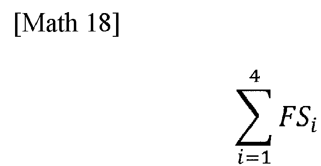
[Math 19]
- Further, the following relation is obtained from formulae (28) and (34). Formula (35) represents a condition of the vehicle required to produce a heave in an upward direction along with a forward diving pitch in the vehicle during turning thereof:

-
Figs. 12 and13 depict yet another embodiment of the present invention. This embodiment pertains to an example in which roll is controlled by usingbrakes 35 equipped to fourwheels 2 that are on the front and the rear and for the left and the right as shown inFig. 12 , in place of theactive stabilizers 5 ofFig. 1 or the in-wheel motors 30 ofFig. 9 , as an actuator that generates a roll moment in thevehicle 1 for the purpose of counteracting roll. Each of thebrakes 35 is a friction brake such as an electric brake or a hydraulic brake. Abrake control device 46 for controlling the brakes for the four wheels is also equipped. -
Fig. 13 shows a block diagram of a vehicleposture control device 21C, in accordance with this embodiment. Thepitch moment calculator 33 in the block diagram ofFig. 6 or10 is not present. The functions of a sideslip angularvelocity estimation unit 23 and aroll moment calculator 24 are identical to those in the example ofFig. 2 . A longitudinal force command value calculator 47 is equipped as an actuator controller for counteracting roll. The longitudinal force command value calculator 47 calculates the longitudinal forces FXi according to formulae (40) to (47) as discussed below, from a roll moment command value that is input thereto. Keep in mind that, since a driver of the vehicle operates the brake pedal to make an input of a deceleration to the vehicle, the vehicleposture control device 21C adds, to the longitudinal forces FXi calculated according to formulae (29) to (32) that are discussed below, longitudinal forces (i.e., braking forces) commensurate with a brake command value and outputs the resultant as a longitudinal force command value. Thebrake control device 46 regulates each of thebrakes 35 in accordance with the longitudinal force command value that is output from the vehicleposture control device 21C. - Next, a scenario will be considered in which an existing brake system is used to implement roll control in accordance with the present invention. The existing brake system refers to a system in which the output from a brake pedal sensor that senses an input to a brake pedal is, in turn, input to an
ECU 9 that transforms the same to a brake command value for execution of brake control. Since it is a braking force that is produced by the brake system, a condition for the longitudinal forces FXi will be defined as follows:
- Roll control will result in a longitudinal acceleration ax of the vehicle as described by formula (37). The suffix x of said symbol ax represents the x-axis of the coordinate system in a two-wheel model and refers to a longitudinal direction of the vehicle.
[Math 20]
- From formula (37), to keep the deceleration of the vehicle to a minimum during the roll control, a braking force from the control needs to be generated only in a single pair of diagonally opposite wheels.
- Also, since the longitudinal forces FXi will be negative (or no greater than zero), there is switching of wheels to be controlled depending on the sign of the roll moment Mφ to be generated as shown below:
[Math 21]
If the roll moment Mφ is positive, then

- Further, formula (24) must be satisfied so as not to generate a yaw moment as a result of the roll control. For this reason, the longitudinal force command value calculator 47, which is the aforementioned actuator controller, outputs longitudinal force command values that apply, for example, approximately equal braking forces to diagonally
opposite wheels 2 of thevehicle 1. - Accordingly, the longitudinal forces FXi when using an existing brake system to carry out roll control in accordance with the present invention are defined as follows:
[Math 22]
If the roll moment Mφ is positive, then



- For all the types of roll control described above, the roll moment Mφ to be generated is calculated according to formula (5), from the sideslip angular velocity β"·" and the yaw rate r as they are being generated in the
vehicle 1. The yaw rate r can be measured with a yaw rate sensor, which is mounted in a vehicle as a constituent component of a vehicle electronic stability control device. On the other hand, to make a direct measurement of a sideslip angular velocity β"·", a costly specialized measurement instrument is required. As an approach to being dispensed with a costly specialized measurement instrument, the sideslip angularvelocity estimation unit 23 may estimate a sideslip angular velocity β"·" from a steering angle δ by employing a vehicle model or may estimate the same from a yaw rate r measured with theyaw rate sensor 15 mounted in the vehicle. - The approach to estimating a sideslip angular velocity β"·" from a steering angle δ by employing a vehicle model involves the following transfer function of the sideslip angular velocity β"·" in response to the steering angle δ, supposing that the aforementioned two-wheel model is employed by way of example:
[Math 23]
- Note that

- Steering angle information obtained by a calculation involving an angle of rotation of, for example, a gear, the amount of displacement of a rack, etc. that is output from a sensor associated with a steering rack can be used as the steering angle δ, in addition to a value calculated from the output from the
steering angle sensor 14 provided in a steering unit. - The approach to estimating a sideslip angular velocity β"·" from a yaw rate r involves, for example, the use of the relation according to formula (3). Formula (3) is modified to obtain the following formula:
[Math 24]
- By using formula (49), a sideslip angular velocity β"·" can be calculated from a lateral acceleration ay and a yaw rate r that are measured with sensors mounted in the vehicle. Yet, on a cant road where the lateral acceleration ay changes with the slope thereof, an error could occur in the estimated sideslip angular velocity β"·". Also, since the model used in both of formulae (48) and (49) is a linear tire model, there may be a larger error under conditions where the lateral force to a tire may saturate. Further, in situations where a longitudinal acceleration is involved, a larger error may likewise occur. As an approach to reducing such errors, a method that uses a nonlinear tire model to estimate a sideslip angular velocity β"·" is proposed in the art (see Non-patent document 3).
- This estimation method employs a nonlinear tire model as described by formula (50):
[Math 25]
- Note that the suffix T represents either a front wheel (f) or a rear wheel (r), KT indicates the cornering power of a tire, βT indicates a sideslip angle at the position of a front wheel or a rear wheel, µ indicates a coefficient of road friction, WT indicates a vertical load on a tire, and XT indicates a longitudinal force to a tire.
- From a lateral force YT to a tire as calculated according to formula (50), a sideslip angular velocity β"·" is estimated according to formula (51). The yaw rate r in formula (50) is a measurement by the
yaw rate sensor 15 mounted in the vehicle:
[Math 26]
- Because the nonlinear tire model in formula (50) takes into account the saturation of a lateral force YT to a tire as well as a vertical load on a tire, the accuracy of the estimate of a lateral force YT to a tire is improved. Thus, the use of formula (51) allows for the accurate estimation of a sideslip angular velocity β "·" from a yaw rate r measured with the
yaw rate sensor 15 mounted in the vehicle. - Although the present invention has been described in terms of the preferred embodiments thereof with reference to the drawings, various additions, modifications, or deletions may be made without departing from the scope of the invention. Accordingly, such variants are included within the scope of the present invention.
-
- 1
- vehicle
- 1A
- vehicle body
- 2
- wheel
- 4
- suspension device
- 4a
- suspension arm
- 4A
- active suspension
- 5
- active stabilizer
- 7A
- support portion vertical force varying mechanism
- 8
- electric motor
- 9
- ECU
- 11
- accelerator pedal sensor
- 12
- brake pedal sensor
- 13
- vehicle velocity sensor
- 14
- steering angle sensor
- 15
- yaw rate sensor
- 16
- acceleration sensor
- 21
- vehicle posture control device
- 22
- stabilizer control device
- 23
- sideslip angular velocity estimation unit
- 24
- roll moment calculator
- 21A to 21C
- vehicle posture control device
- 25
- actuator controller
- 26
- front and rear wheels roll moment calculator
- 27
- command transformer
- 31
- suspension control device
- 33
- pitch moment calculator
- 34
- longitudinal force command value calculator
- 34A
- actuator controller
- 30
- in-wheel motor
- 35
- brake
- 46
- brake control device
- 41
- motor control device
Claims (16)
- A vehicle posture control device configured to be installed in a vehicle provided with an actuator configured to generate a roll moment, the device comprising:a roll moment calculator configured to calculate a roll moment command value to control the actuator such that a roll motion is generated in conjunction with a yaw motion in the vehicle during turning thereof, the roll moment calculator being configured to calculate the roll moment command value for output, on the basis of a sideslip angular velocity and a vehicle velocity of the vehicle; andan actuator controller configured to control the actuator by using the calculated roll moment command value.
- The vehicle posture control device as claimed in claim 1, wherein the roll moment calculator comprises a formula according to which the roll moment command value is calculated and which includes a term that compensates for phase delay of a roll motion resulting from a yaw rate.
- The vehicle posture control device as claimed in claim 1 or 2, wherein the vehicle is further provided with an actuator configured to generate a pitch moment during turning thereof, and the vehicle posture control device further comprises:a pitch moment calculator configured to calculate a pitch moment command value, the pitch moment calculator being configured to calculate the pitch moment command value, on the basis of at least a yaw rate and the vehicle velocity of the vehicle;wherein the pitch moment calculator controls the actuator by using the calculated pitch moment command value.
- The vehicle posture control device as claimed in claim 3, wherein the pitch moment calculator is configured to provide the pitch moment command value as a value that compensates for a delay spanning between generation of the pitch moment and occurrence of change of a pitch angle in the vehicle and caused by characteristics of a suspension.
- The vehicle posture control device as claimed in any one of claims 1 to 4, wherein the actuator configured to generate the roll moment is a device mounted to a suspension and configured to apply a force in a vertical direction to the vehicle through a constituent member of the suspension to generate the roll moment.
- The vehicle posture control device as claimed in claim 3 or 4, wherein at least one of the actuator configured to generate the roll moment or the actuator configured to generate the pitch moment is a device mounted to a suspension and configured to apply a force in a vertical direction to the vehicle through a constituent member of the suspension to generate either one of the roll moment or the pitch moment.
- The vehicle posture control device as claimed in claim 5, wherein the actuator configured to generate the roll moment is a device capable of producing a longitudinal force to a tire and configured to apply a vertical force to the vehicle by cooperating with a link arrangement of a suspension with an anti-dive angle at a front wheel and an anti-squat angle at a rear wheel.
- The vehicle posture control device as claimed in claim 6, wherein the actuator configured to generate the roll moment and the actuator configured to generate the pitch moment are represented by a device capable of producing a longitudinal force to a tire and configured to apply a vertical force to the vehicle by cooperating with a link arrangement of a suspension with an anti-dive angle at a front wheel and an anti-squat angle at a rear wheel.
- The vehicle posture control device as claimed in claim 3 or 4, wherein the pitch moment calculator is configured such that a larger pitch angle in the direction of forward diving is generated in the vehicle in response to a greater absolute value of a yaw rate.
- The vehicle posture control device as claimed in claim 8, wherein the vehicle posture control device is configured to be installed in a vehicle in which a magnitude of a product between a tangent of an anti-dive angle at a front wheel and a distance in a longitudinal direction between a point of center of gravity of the vehicle and a point of a suspension at the front wheel at which a spring and a damper thereof bear a sprung mass of the vehicle is smaller than a magnitude of a product between a tangent of an anti-dive angle at a rear wheel and a distance in the longitudinal direction between the point of center of gravity of the vehicle and a point of a suspension at the rear wheel at which a spring and a damper thereof bear the sprung mass of the vehicle.
- The vehicle posture control device as claimed in any one of claims 1 to 10, wherein the roll moment calculator is configured to estimate the sideslip angular velocity from steering angle information sensed by a steering angle sensor equipped to the vehicle.
- The vehicle posture control device as claimed in any one of claims 1 to 10, wherein the roll moment calculator is configured to estimate the sideslip angular velocity at least from a yaw rate sensed by a yaw rate sensor equipped to the vehicle.
- The vehicle posture control device as claimed in claim 7, wherein the longitudinal force produced in roll control by means of the roll moment calculator is such that a total value of longitudinal forces to front and rear right wheels is an approximately equal value to a total value of longitudinal forces to front and rear left wheels.
- The vehicle posture control device as claimed in claim 8, wherein the longitudinal force produced in roll control or pitch control by means of the roll moment calculator or the pitch moment calculator is such that a total value of longitudinal forces to front and rear right wheels is an approximately equal value to a total value of longitudinal forces to front and rear left wheels.
- The vehicle posture control device as claimed in claim 7 or 8, wherein the actuator controller is configured such that, when the actuator configured to generate the roll moment is a device that uses a braking force to generate the roll moment, approximately equal braking forces are applied to diagonally opposite wheels of the vehicle.
- A vehicle comprising a vehicle posture control device as claimed in any one of claims 1 to 15, the vehicle posture control device being installed therein.
Applications Claiming Priority (3)
| Application Number | Priority Date | Filing Date | Title |
|---|---|---|---|
| JP2020173949 | 2020-10-15 | ||
| JP2021034820A JP2022065602A (en) | 2020-10-15 | 2021-03-04 | Vehicle attitude control device and vehicle |
| PCT/JP2021/037011 WO2022080212A1 (en) | 2020-10-15 | 2021-10-06 | Vehicle attitude control device and vehicle |
Publications (2)
| Publication Number | Publication Date |
|---|---|
| EP4230447A1 true EP4230447A1 (en) | 2023-08-23 |
| EP4230447A4 EP4230447A4 (en) | 2024-11-13 |
Family
ID=81209028
Family Applications (1)
| Application Number | Title | Priority Date | Filing Date |
|---|---|---|---|
| EP21879952.6A Withdrawn EP4230447A4 (en) | 2020-10-15 | 2021-10-06 | VEHICLE POSITION CONTROL DEVICE AND VEHICLE |
Country Status (3)
| Country | Link |
|---|---|
| US (1) | US20230256957A1 (en) |
| EP (1) | EP4230447A4 (en) |
| WO (1) | WO2022080212A1 (en) |
Families Citing this family (2)
| Publication number | Priority date | Publication date | Assignee | Title |
|---|---|---|---|---|
| CN119502617A (en) * | 2024-10-15 | 2025-02-25 | 中联重科股份有限公司 | Axle load leveling method for operating machinery and operating machinery |
| CN120973038B (en) * | 2025-10-21 | 2026-01-02 | 台州学院 | Gesture stable control method and system for pipeline robot |
Family Cites Families (19)
| Publication number | Priority date | Publication date | Assignee | Title |
|---|---|---|---|---|
| JPH03224814A (en) * | 1990-01-29 | 1991-10-03 | Matsushita Electric Ind Co Ltd | Active suspension controller |
| JP2004322755A (en) * | 2003-04-23 | 2004-11-18 | Aisin Seiki Co Ltd | Vehicle suspension |
| US7197388B2 (en) * | 2003-11-06 | 2007-03-27 | Ford Global Technologies, Llc | Roll stability control system for an automotive vehicle using an external environmental sensing system |
| JP4285343B2 (en) * | 2004-07-07 | 2009-06-24 | トヨタ自動車株式会社 | Roll stiffness control device for vehicle |
| JP2006027570A (en) * | 2004-07-21 | 2006-02-02 | Honda Motor Co Ltd | Vehicle behavior estimation method |
| JP4732061B2 (en) | 2004-08-06 | 2011-07-27 | 本田技研工業株式会社 | Suspension control device |
| JP4810962B2 (en) | 2005-10-13 | 2011-11-09 | トヨタ自動車株式会社 | Method and apparatus for controlling vehicle suspension |
| JP4155299B2 (en) * | 2005-12-26 | 2008-09-24 | トヨタ自動車株式会社 | Vehicle damping force control device |
| JP2008260439A (en) * | 2007-04-12 | 2008-10-30 | Toyota Motor Corp | Vehicle behavior control apparatus and vehicle behavior control method |
| JP4872939B2 (en) * | 2008-02-12 | 2012-02-08 | トヨタ自動車株式会社 | Vehicle damping force control device |
| JP5321603B2 (en) * | 2009-02-16 | 2013-10-23 | トヨタ自動車株式会社 | Vehicle stabilizer control device |
| JP5809506B2 (en) * | 2011-09-27 | 2015-11-11 | 日立オートモティブシステムズ株式会社 | Vehicle motion control device and suspension control device |
| JP5862273B2 (en) * | 2011-12-19 | 2016-02-16 | トヨタ自動車株式会社 | Vehicle behavior control device |
| JP5803687B2 (en) * | 2012-01-17 | 2015-11-04 | トヨタ自動車株式会社 | Vehicle travel control device |
| US9283959B2 (en) * | 2012-02-24 | 2016-03-15 | Toyota Jidosha Kabushiki Kaisha | Vehicle behavior control apparatus |
| JP7175107B2 (en) * | 2018-05-31 | 2022-11-18 | 株式会社小松製作所 | Blade control device and blade control method |
| JP7172414B2 (en) * | 2018-10-12 | 2022-11-16 | トヨタ自動車株式会社 | Vehicle roll vibration damping control device |
| JP6734912B2 (en) * | 2018-12-24 | 2020-08-05 | 本田技研工業株式会社 | Vehicle suspension controller |
| DE102019206738A1 (en) * | 2019-05-09 | 2020-11-12 | Zf Friedrichshafen Ag | Method, control unit and system for stabilizing a vehicle |
-
2021
- 2021-10-06 WO PCT/JP2021/037011 patent/WO2022080212A1/en not_active Ceased
- 2021-10-06 EP EP21879952.6A patent/EP4230447A4/en not_active Withdrawn
-
2023
- 2023-04-13 US US18/134,380 patent/US20230256957A1/en not_active Abandoned
Also Published As
| Publication number | Publication date |
|---|---|
| WO2022080212A1 (en) | 2022-04-21 |
| EP4230447A4 (en) | 2024-11-13 |
| US20230256957A1 (en) | 2023-08-17 |
| WO2022080212A8 (en) | 2023-04-20 |
Similar Documents
| Publication | Publication Date | Title |
|---|---|---|
| US8718872B2 (en) | Vehicle attitude controller | |
| CN102343778B (en) | Vehicle body attitude control apparatus | |
| JP4285343B2 (en) | Roll stiffness control device for vehicle | |
| RU2421354C2 (en) | Automotive drive device | |
| CN113320525B (en) | Methods for controlling road vehicles with variable stiffness and steering rear wheels while driving along curves. | |
| JP6753911B2 (en) | Control device for variable damping force damper | |
| JP7109406B2 (en) | vehicle controller | |
| JPH04504701A (en) | Control device for suspension control of land vehicles | |
| US20230256957A1 (en) | Vehicle posture control device and vehicle | |
| CN103010208A (en) | Vehicle motion control apparatus and suspension control apparatus | |
| WO2021059845A1 (en) | Vehicle movement control device | |
| WO2021059544A1 (en) | State quantity calculation device, control device, and vehicle | |
| JP2022191964A (en) | Vehicle motion control device, vehicle motion control system and vehicle | |
| Orend | Modelling and control of a vehicle with single-wheel chassis actuators | |
| Sorniotti et al. | Vehicle dynamics simulation to develop an active roll control system | |
| WO2019097732A1 (en) | Vehicle state inference device, control device, suspension control device, suspension device, steering control device, and steering device | |
| JP7059341B1 (en) | Suspension control device, vehicle and suspension control method | |
| WO2022181468A1 (en) | Vehicle motion control device, vehicle motion control system, and vehicle | |
| JP2022112714A (en) | Vehicle motion control device and vehicle | |
| JP2022065602A (en) | Vehicle attitude control device and vehicle | |
| CN117480080A (en) | Vehicle motion control device, vehicle motion control system and vehicle | |
| JP7095970B2 (en) | Vehicle control unit | |
| CN117500707A (en) | Vehicle motion control devices, vehicles and systems | |
| JP2022129650A (en) | Vehicle motion control device, vehicle motion control system and vehicle | |
| JP5500012B2 (en) | Vehicle control apparatus and vehicle control method |
Legal Events
| Date | Code | Title | Description |
|---|---|---|---|
| STAA | Information on the status of an ep patent application or granted ep patent |
Free format text: STATUS: THE INTERNATIONAL PUBLICATION HAS BEEN MADE |
|
| PUAI | Public reference made under article 153(3) epc to a published international application that has entered the european phase |
Free format text: ORIGINAL CODE: 0009012 |
|
| STAA | Information on the status of an ep patent application or granted ep patent |
Free format text: STATUS: REQUEST FOR EXAMINATION WAS MADE |
|
| 17P | Request for examination filed |
Effective date: 20230503 |
|
| AK | Designated contracting states |
Kind code of ref document: A1 Designated state(s): AL AT BE BG CH CY CZ DE DK EE ES FI FR GB GR HR HU IE IS IT LI LT LU LV MC MK MT NL NO PL PT RO RS SE SI SK SM TR |
|
| DAV | Request for validation of the european patent (deleted) | ||
| DAX | Request for extension of the european patent (deleted) | ||
| REG | Reference to a national code |
Ref country code: DE Ref legal event code: R079 Free format text: PREVIOUS MAIN CLASS: B60G0017015000 Ipc: B60G0017016000 |
|
| A4 | Supplementary search report drawn up and despatched |
Effective date: 20241014 |
|
| RIC1 | Information provided on ipc code assigned before grant |
Ipc: B60W 30/02 20120101ALI20241008BHEP Ipc: B60W 10/184 20120101ALI20241008BHEP Ipc: B60W 10/18 20120101ALI20241008BHEP Ipc: B60G 17/0195 20060101ALI20241008BHEP Ipc: B60G 17/018 20060101ALI20241008BHEP Ipc: B60G 21/055 20060101ALI20241008BHEP Ipc: B60W 30/045 20120101ALI20241008BHEP Ipc: B60W 10/22 20060101ALI20241008BHEP Ipc: B60W 10/20 20060101ALI20241008BHEP Ipc: B60W 10/00 20060101ALI20241008BHEP Ipc: B60T 8/1755 20060101ALI20241008BHEP Ipc: B60W 40/114 20120101ALI20241008BHEP Ipc: B60W 40/112 20120101ALI20241008BHEP Ipc: B60W 40/11 20120101ALI20241008BHEP Ipc: B60W 40/10 20120101ALI20241008BHEP Ipc: B60G 17/016 20060101AFI20241008BHEP |
|
| STAA | Information on the status of an ep patent application or granted ep patent |
Free format text: STATUS: THE APPLICATION HAS BEEN WITHDRAWN |
|
| 18W | Application withdrawn |
Effective date: 20250312 |