EP4230442A1 - Tire pneumatic pressure monitoring system and tire pneumatic pressure monitoring program - Google Patents
Tire pneumatic pressure monitoring system and tire pneumatic pressure monitoring program Download PDFInfo
- Publication number
- EP4230442A1 EP4230442A1 EP21879961.7A EP21879961A EP4230442A1 EP 4230442 A1 EP4230442 A1 EP 4230442A1 EP 21879961 A EP21879961 A EP 21879961A EP 4230442 A1 EP4230442 A1 EP 4230442A1
- Authority
- EP
- European Patent Office
- Prior art keywords
- air pressure
- pressure data
- tire
- data
- decrease
- Prior art date
- Legal status (The legal status is an assumption and is not a legal conclusion. Google has not performed a legal analysis and makes no representation as to the accuracy of the status listed.)
- Granted
Links
Images



Classifications
-
- G—PHYSICS
- G01—MEASURING; TESTING
- G01L—MEASURING FORCE, STRESS, TORQUE, WORK, MECHANICAL POWER, MECHANICAL EFFICIENCY, OR FLUID PRESSURE
- G01L17/00—Devices or apparatus for measuring tyre pressure or the pressure in other inflated bodies
-
- B—PERFORMING OPERATIONS; TRANSPORTING
- B60—VEHICLES IN GENERAL
- B60C—VEHICLE TYRES; TYRE INFLATION; TYRE CHANGING; CONNECTING VALVES TO INFLATABLE ELASTIC BODIES IN GENERAL; DEVICES OR ARRANGEMENTS RELATED TO TYRES
- B60C23/00—Devices for measuring, signalling, controlling, or distributing tyre pressure or temperature, specially adapted for mounting on vehicles; Arrangement of tyre inflating devices on vehicles, e.g. of pumps or of tanks; Tyre cooling arrangements
- B60C23/02—Signalling devices actuated by tyre pressure
- B60C23/04—Signalling devices actuated by tyre pressure mounted on the wheel or tyre
- B60C23/0408—Signalling devices actuated by tyre pressure mounted on the wheel or tyre transmitting the signals by non-mechanical means from the wheel or tyre to a vehicle body mounted receiver
- B60C23/0479—Communicating with external units being not part of the vehicle, e.g. tools for diagnostic, mobile phones, electronic keys or service stations
-
- B—PERFORMING OPERATIONS; TRANSPORTING
- B60—VEHICLES IN GENERAL
- B60C—VEHICLE TYRES; TYRE INFLATION; TYRE CHANGING; CONNECTING VALVES TO INFLATABLE ELASTIC BODIES IN GENERAL; DEVICES OR ARRANGEMENTS RELATED TO TYRES
- B60C23/00—Devices for measuring, signalling, controlling, or distributing tyre pressure or temperature, specially adapted for mounting on vehicles; Arrangement of tyre inflating devices on vehicles, e.g. of pumps or of tanks; Tyre cooling arrangements
- B60C23/02—Signalling devices actuated by tyre pressure
- B60C23/04—Signalling devices actuated by tyre pressure mounted on the wheel or tyre
- B60C23/0408—Signalling devices actuated by tyre pressure mounted on the wheel or tyre transmitting the signals by non-mechanical means from the wheel or tyre to a vehicle body mounted receiver
- B60C23/0474—Measurement control, e.g. setting measurement rate or calibrating of sensors; Further processing of measured values, e.g. filtering, compensating or slope monitoring
-
- B—PERFORMING OPERATIONS; TRANSPORTING
- B60—VEHICLES IN GENERAL
- B60C—VEHICLE TYRES; TYRE INFLATION; TYRE CHANGING; CONNECTING VALVES TO INFLATABLE ELASTIC BODIES IN GENERAL; DEVICES OR ARRANGEMENTS RELATED TO TYRES
- B60C23/00—Devices for measuring, signalling, controlling, or distributing tyre pressure or temperature, specially adapted for mounting on vehicles; Arrangement of tyre inflating devices on vehicles, e.g. of pumps or of tanks; Tyre cooling arrangements
- B60C23/02—Signalling devices actuated by tyre pressure
- B60C23/04—Signalling devices actuated by tyre pressure mounted on the wheel or tyre
- B60C23/0408—Signalling devices actuated by tyre pressure mounted on the wheel or tyre transmitting the signals by non-mechanical means from the wheel or tyre to a vehicle body mounted receiver
- B60C23/0474—Measurement control, e.g. setting measurement rate or calibrating of sensors; Further processing of measured values, e.g. filtering, compensating or slope monitoring
- B60C23/0477—Evaluating waveform of pressure readings
-
- G—PHYSICS
- G01—MEASURING; TESTING
- G01L—MEASURING FORCE, STRESS, TORQUE, WORK, MECHANICAL POWER, MECHANICAL EFFICIENCY, OR FLUID PRESSURE
- G01L19/00—Details of, or accessories for, apparatus for measuring steady or quasi-steady pressure of a fluent medium insofar as such details or accessories are not special to particular types of pressure gauges
- G01L19/08—Means for indicating or recording, e.g. for remote indication
- G01L19/086—Means for indicating or recording, e.g. for remote indication for remote indication
-
- G—PHYSICS
- G01—MEASURING; TESTING
- G01M—TESTING STATIC OR DYNAMIC BALANCE OF MACHINES OR STRUCTURES; TESTING OF STRUCTURES OR APPARATUS, NOT OTHERWISE PROVIDED FOR
- G01M17/00—Testing of vehicles
- G01M17/007—Wheeled or endless-tracked vehicles
- G01M17/02—Tyres
Definitions
- the present invention relates to a tire air pressure monitoring system and a tire air pressure monitoring program that monitor the air pressure of a pneumatic tire.
- Patent Literature 1 a technology has been proposed to more reliably provide notification of a decrease in tire air pressure on the basis of a warning threshold value that follows changes in air pressure within a tire as a vehicle travels.
- Patent Literature 1 Japanese Unexamined Patent Application Publication No. 2012-171463
- an object of the present invention is to provide a tire air pressure monitoring system and a tire air pressure monitoring program that can accurately detect a decrease in air pressure even when the tire air pressure detection period is short or when the rate of decrease in air pressure is gradual.
- a tire air pressure monitoring system (S1a) includes: a data acquisition unit that acquires tire air pressure data at each fixed detection period; a storage unit that stores newly acquired air pressure data P(0), and air pressure data P(1) to P(N) acquired 1 to N periods prior to the air pressure data P(0) (where N is a natural number of 2 or more); a determination unit that determines a state in which air pressure has decreased, on the basis of the air pressure data; and a communication unit that transmits a determination result of the determination unit to an external device, in which the determination unit compares each piece of the air pressure data P(1) to P(n) (where n is a natural number from 1 to N) with the air pressure data P(0) to calculate decrease values, compares the decrease values with a preset first threshold value, and determines that tire air pressure is decreasing when at least one decrease value is greater than or equal to the first threshold value.
- a tire air pressure monitoring system (S1b) includes: a data acquisition unit that acquires tire air pressure data at each fixed detection period; a storage unit that stores newly acquired air pressure data P(0), and data P(1) to P(N) acquired 1 to N periods prior to the air pressure data P(0) (where N is a natural number of 2 or more); a determination unit that determines a state in which air pressure has decreased, on the basis of the air pressure data; and a communication unit that transmits a determination result of the determination unit to an external device, in which, in a case where the determination unit has determined that tire air pressure is decreasing according to a decrease value between air pressure data P(k) (where k is a natural number from 1 to N) and the air pressure data P(0), when all pieces of the air pressure data P(k + 1) to P(N) are greater than a sum of the air pressure data P(0) and a preset second threshold value, it is determined that the tire air pressure is decreasing.
- a tire air pressure monitoring program executed by a computer provided in a tire air pressure monitoring system includes: a step of acquiring tire air pressure data at each fixed detection period; a step of storing newly acquired air pressure data P(0), and air pressure data P(1) to P(N) acquired 1 to N periods prior to the air pressure data P(0) (where N is a natural number of 2 or more); a step of determining a state in which air pressure has decreased, on the basis of the air pressure data; and a step of transmitting a determination result to an external device, in which, in the step of determining the state in which air pressure has decreased, each piece of the air pressure data P(1) to P(n) (where n is a natural number from 1 to N) is compared with the air pressure data P(0) to calculate decrease values, the decrease values are compared with a preset first threshold value, and it is determined that tire air pressure is decreasing when at least one decrease value is greater than or equal to the first threshold value.
- a tire air pressure monitoring program executed by a computer provided in a tire air pressure monitoring system includes: a step of acquiring tire air pressure data at each fixed detection period; a step of storing newly acquired air pressure data P(0), and air pressure data P(1) to P(N) acquired 1 to N periods prior to the air pressure data P(0) (where N is a natural number of 2 or more); a step of determining a state in which air pressure has decreased, on the basis of the air pressure data; and a step of transmitting a determination result to an external device, in which, in the step of determining the state in which air pressure has decreased, in a case where it is determined that tire air pressure is decreasing according to a decrease value between air pressure data P(k) (where k is a natural number from 1 to N) and the air pressure data P(0), when all pieces of the air pressure data P(k + 1) to P(N) are greater than a sum of the air pressure data P(0) and a preset second threshold value, it is determined that the tire
- the step of determining the state in which air pressure has decreased in a case where it is determined that the tire air pressure is decreasing according to a decrease value between the air pressure data P(k) and the air pressure data P(0), with regard to hypothetical air pressure data P' when it is assumed that air pressure has decreased by a certain proportion from the air pressure data P(k) to P(0), when air pressure data P(k - 1) to P(1) and the hypothetical air pressure data P' (k - 1) to P' (1) are compared in a same period and all are within a certain range, it may be determined that the tire air pressure is decreasing.
- a tire air pressure monitoring system S1a according to a first embodiment of the present invention will be described with reference to FIGS. 1 to 3 .
- a schematic configuration of the tire air pressure monitoring system S1a according to the first embodiment will be described with reference to the schematic configuration diagram of FIG. 1 .
- the tire air pressure monitoring system S1a includes a sensor unit SU provided on a pneumatic tire (hereafter referred to simply as a tire) 10 side.
- FIG. 1 illustrates a cross-sectional shape along a tire width direction of a tire 10 mounted on a rim wheel 90.
- a tread portion 20 is a portion where the tire 10 attached to a vehicle, which is not illustrated, comes into contact with a road surface when rolling on the road surface.
- a tread pattern corresponding to the type of vehicle and the required performance is formed in the tread portion 20.
- the sensor unit SU which detects internal pressure information of the tire 10, is provided on an inner surface 10a of the tire 10 to which the tire air pressure monitoring system S1a can be applied.
- the sensor unit SU may be capable of acquiring temperature information and the like.
- the sensor unit SU is provided on the inner surface 10a facing the tread portion 20. More specifically, the sensor unit SU is attached to the surface of an inner liner (not illustrated) that prevents leakage of gases such as air filled in the internal space of the pneumatic tire 10 mounted on the rim wheel 90.
- the sensor unit SU is not limited to the inner surface 10a facing the tread portion 20, and may be provided on an inner surface at a sidewall 30 side of the tire 10.
- the sensor unit SU is preferably provided on each tire 10 attached to the vehicle. This is because it is desirable to monitor the leak situation or the like of each tire 10 so as to ensure the safety of the vehicle.
- the sensor unit SU need not necessarily be attached to the inner side surface of the tire 10.
- a configuration may be adopted in which a part or all of the sensor unit SU is embedded inside the tire 10.
- the sensor unit SU may be attached to the wheel to which the tire 10 is attached.
- the sensor unit SU includes an internal pressure sensor SN that detects internal pressure (air pressure) of the tire 10, a transmitter 150 that transmits detection data at each fixed detection period (for example, 12 sec, 30 sec, 60 sec, or the like) to an external device (in-vehicle device (ECU) or the like), a processor 100, and a battery 151 that feeds the internal pressure sensor SN, the processor 100, and the transmitter 150.
- an internal pressure sensor SN that detects internal pressure (air pressure) of the tire 10
- a transmitter 150 that transmits detection data at each fixed detection period (for example, 12 sec, 30 sec, 60 sec, or the like) to an external device (in-vehicle device (ECU) or the like) to an external device (in-vehicle device (ECU) or the like) to an external device (in-vehicle device (ECU) or the like) to an external device (in-vehicle device (ECU) or the like)
- ECU in-vehicle device
- the processor 100 is provided with a storage unit 102 configured of a flash memory or the like that stores newly acquired air pressure data P(0), and air pressure data P(1) to P(N) acquired 1 to N periods prior to the air pressure data P(0) (where N is a natural number of 2 or more).
- a storage unit 102 configured of a flash memory or the like that stores newly acquired air pressure data P(0), and air pressure data P(1) to P(N) acquired 1 to N periods prior to the air pressure data P(0) (where N is a natural number of 2 or more).
- N in P (N) can be 3 to 5. It is thereby possible to achieve balance between handling a gradual leak in air pressure and processing efficiency.
- the processor 100 is provided with a determination unit 103 configured of a CPU or the like that determines a state in which air pressure has decreased, on the basis of the air pressure data.
- the transmitter 150 transmits the determination result of the determination unit 103 to an external device 250 such as an ECU, via a communication line N1.
- the determination unit 103 compares each piece of the air pressure data P(1) to P(n) (where n is a natural number from 1 to N) with the air pressure data P(0) to calculate decrease values.
- the decrease values are compared with a preset first threshold value th1, and when at least one decrease value is greater than or equal to the first threshold value th1, it is determined that the tire air pressure is decreasing.
- step S10 tire air pressure data is acquired at each fixed detection period, and the processing moves to step S11.
- step S11 newly acquired air pressure data P(0) and air pressure data P(1) to P(N) acquired 1 to N periods prior to the air pressure data P(0) (where N is a natural number of 2 or more) are stored by the storage unit 102, and the processing moves to step S12.
- step S12 each piece of the air pressure data P(1) to P(n) (where n is a natural number from 1 to N) is compared with the air pressure data P(0) to calculate decrease values (for example, P(0) - P(1) and the like), and the processing moves to step S13.
- step S13 a comparison is made with a preset first threshold value (th1), and the processing moves to step S14.
- the first threshold value th1 is a threshold value for an LSB difference of the sensor that is considered to have a significant difference, taking into account errors of a sensor element constituting the internal pressure sensor SN. Furthermore, it is understood that when there is a decrease greater than or equal to the first threshold value th1, a sudden decrease in internal pressure can be determined.
- the first threshold value th1 depends on the measurement period, and can be 3 LSB (approximately 3 to 10 kPa) in 30 sec or less, or 4 LSB (approximately 5 to 15 kPa) in 60 sec, for example.
- step S14 if at least one decrease value is greater than or equal to the first threshold value (th1) (in other words, for example, if P(0) - P(1) ⁇ th1 or the like), it is determined that the tire air pressure is decreasing, and the processing moves to step S15.
- th1 the first threshold value
- step S15 the determination result is transmitted to the external apparatus (ECU or the like) 250, and the processing ends.
- a tire air pressure monitoring system S1b according to a second embodiment of the present invention will be described with reference to FIGS. 1 , 2 , 4A , 4B , and 5 .
- the functional configuration and the like of the tire air pressure monitoring system S1b according to the second embodiment are the same as those of the tire air pressure monitoring system S1a according to the first embodiment, and therefore duplicate descriptions are omitted.
- the determination unit 103 has determined that the tire air pressure is decreasing according to a decrease value between air pressure data P(k) (where k is a natural number from 1 to N) and the air pressure data P(0), when all pieces of the air pressure data P(k + 1) to P(N) are greater than the sum of the air pressure data P(0) and a preset second threshold value, it is determined that the tire air pressure is decreasing.
- the determination unit 103 has determined that the tire air pressure is decreasing according to a decrease value between air pressure data P(k) and the air pressure data P(0), with regard to hypothetical air pressure data P' when it is assumed that air pressure has decreased by a certain proportion from the air pressure data P(k) to P(0), when air pressure data P(k - 1) to P(1) and the hypothetical air pressure data P'(k - 1) to P'(1) are compared in the same period and all are within a certain range, it can be determined that the tire air pressure is decreasing.
- This determination processing in addition to detecting a decrease in air pressure such as when there is a gradual leak in air pressure, makes it possible to more reliably provide notification (warning) of a decrease in air pressure by suppressing the effect of a temporary decrease in pressure such as when the tire has ridden up a curb.
- step S101 it is determined whether or not P(0) - P(1) ⁇ th1.
- step S102 it is determined whether or not P(2 to 5) > P(0) + th2.
- the second threshold value th2 is an upper limit for errors of the sensor element constituting the internal pressure sensor SN, and can be a value that is approximately twice the error LSB relative to the actual value (in other words, the maximum difference LSB between measurement samples when there is no change in pressure).
- the second threshold value th2 can be approximately 5 to 10 kPa, for example.
- step S102 determines whether the processing is "No" or "No" if the determination result of step S102 is "No", the processing moves to step S111, and the processing ends without a warning being provided.
- step S110 a warning is provided that there has been a sudden decrease in tire pressure due to the tire riding up a curb or the like, and the processing ends.
- step S101 if "No" is determined in step S101, the processing moves to step S103.
- step S103 it is determined whether or not P(0) - P(2) ⁇ th1 and P(1) is within a predetermined range.
- P(0) - P(2) ⁇ th1 refers to a case such as being in the range R1 (>th1) in the graph (vertical axis: LSB, horizontal axis: measurement period) illustrated in FIG. 5(a) , for example.
- P(1) being within a predetermined range refers to a case such as P(1) being within the range R2 in the graph illustrated in FIG. 5(a) , for example.
- step S103 the processing moves to step S104.
- step S104 it is determined whether or not P(3 to 5) > P(0) + th2.
- step S111 If the determination result is "No”, the processing moves to step S111, and the processing ends without a warning being provided.
- step S110 a warning is provided that there has been a sudden decrease in tire pressure due to the tire riding up a curb or the like, and the processing ends.
- step S103 if "No" is determined in step S103, the processing moves to step S105.
- step S105 it is determined whether or not P(0) - P(3) ⁇ th1 and P(1, 2) are within a predetermined range.
- P(0) - P(3) ⁇ th1 refers to a case such as being within the range R4 in the graph (vertical axis: LSB, horizontal axis: measurement period) illustrated in FIG. 5(b) , for example.
- P(1, 2) being within a predetermined range refers to a case such as P(1, 2) being within the range R8 or R7 in the graph illustrated in FIG. 5(b) , for example.
- step S105 the processing moves to step S106.
- step S106 it is determined whether or not P(4, 5) > P(0) + th2.
- step S111 If the determination result is "No”, the processing moves to step S111, and the processing ends without a warning being provided.
- step S110 a warning is provided that there has been a sudden decrease in tire pressure due to the tire riding up a curb or the like, and the processing ends.
- step S105 if "No" is determined in step S105, the processing moves to step S107.
- step S107 it is determined whether or not P(0) - P(4) ⁇ th1 and P(1 to 3) are within a predetermined range.
- P(0) - P(4) ⁇ th1 refers to a case such as being within the range R4 in the graph illustrated in FIG. 5(b) , for example.
- P(1 to 3) being within a predetermined range refers to a case such as P(1 to 3) being within the ranges R6 to R8 in the graph illustrated in FIG. 5(b) , for example.
- step S107 determines whether the determination result in step S107 is "Yes" or not.
- step S108 it is determined whether or not P(5) > P(0) + th2.
- step S111 If the determination result is "No”, the processing moves to step S111, and the processing ends without a warning being provided.
- step S110 a warning is provided that there has been a sudden decrease in tire pressure due to the tire riding up a curb or the like, and the processing ends.
- step S107 if "No" is determined in step S107, the processing moves to step S109.
- step S109 it is determined whether or not P(0) - P(5) ⁇ th1 and P(1 to 4) are within a predetermined range.
- P(0) - P(5) ⁇ th1 refers to a case such as being within the range R4 in the graph illustrated in FIG. 5(b) , for example.
- P(1 to 4) being within a predetermined range refers to a case such as P(1 to 4) being within the ranges R5 to R8 in the graph illustrated in FIG. 5(b) , for example.
- step S111 the processing moves to step S111, and the processing ends without a warning being provided.
- step S110 a warning is provided that there has been a sudden decrease in tire pressure due to the tire riding up a curb or the like, and the processing ends.
- step S201 it is determined whether or not P(0) - P(1) ⁇ th3.
- P(0) is newly acquired air pressure data
- P(1) is air pressure data acquired one period before
- th3 is a preset third threshold value.
- the third threshold value th3 is a threshold value for an LSB difference of the internal pressure sensor SN at which a sudden decrease will surely occur even when the tire has ridden up a curb or the like. Furthermore, it is understood that when there is a decrease greater than or equal to the third threshold value th3, a sudden decrease in internal pressure can be determined.
- the third threshold value th3 can be approximately 10 to 30 kPa, for example.
- step S202 a warning such as "The tire pressure is decreasing. Please perform tire maintenance.” is notified to the driver or the like, and the processing ends.
- step S201 determines whether "No" is determined in step S201 or "No" is determined in step S201. If "No" is determined in step S201, the processing moves to step S203, and the processing ends without a warning being provided.
- the determination unit 103 illustrated in FIG. 2 may be implemented such that the air pressure data P(1) and P(0) are compared and a decrease values is calculated, the decrease value is compared with the third threshold value th3, and it is determined that the tire air pressure is decreasing when the decrease value is greater than or equal to the third threshold value th3.
- the tire air pressure monitoring program in which determination processing is executed can have: a step of acquiring tire air pressure data at each fixed detection period; a step of storing newly acquired air pressure data P(0), and air pressure data P(1) to P(N) that is acquired 1 to N periods prior to the air pressure data P(0) (where N is a natural number of 2 or more); a step of determining a state in which air pressure has decreased, on the basis of the air pressure data; and a step of transmitting a determination result to the external device (ECU or the like) 250.
- the step of determining a state in which air pressure has decreased it is possible to compare each piece of air pressure data P(1) to P(n) (where n is a natural number from 1 to N) with the air pressure data P(0) to calculate decrease values, compare the decrease values with the preset first threshold value th1, and determine that the tire air pressure is decreasing when at least one decrease value is greater than or equal to the first threshold value th1.
- a tire air pressure monitoring program can have: a step of acquiring tire air pressure data at each fixed detection period; a step of storing newly acquired air pressure data P(0), and air pressure data P(1) to P(N) acquired 1 to N periods prior to the air pressure data P(0) (where N is a natural number of 2 or more); a step of determining a state in which air pressure has decreased, on the basis of the air pressure data; and a step of transmitting a determination result to the external device (ECU or the like) 250.
- the step of determining a state in which air pressure has decreased when it is determined that the tire air pressure is decreasing according to a decrease value between air pressure data P(k) (where k is a natural number from 1 to N) and the air pressure data P(0), and all pieces of air pressure data P(k + 1) to P(N) are greater than the sum of the air pressure data P(0) and the preset second threshold value th2, it can be determined that the tire air pressure is decreasing.
- the step of determining a state in which air pressure has decreased may be implemented such that, in a case where it is determined that the tire air pressure is decreasing according to a decrease value between air pressure data P(k) and the air pressure data P(0), with regard to hypothetical air pressure data P' when it is assumed that air pressure has decreased by a certain proportion from the air pressure data P(k) to P(0), when air pressure data P(k - 1) to P(1) and the hypothetical air pressure data P'(k - 1) to P' (1) are compared in the same period and all are within a certain range, it is determined that the tire air pressure is decreasing.
- the rate of the detection period may be changed. A decrease in pressure can thereby be detected at an early stage according to the situation.
- the value of P(0) may be copied to P(1) to P(N) when the detection period changes. This can prevent an erroneous determination by resetting a stored value.
- the second threshold value th2 may be changed according to the detection period.
- a tire air pressure monitoring system S1c according to a modified example will be described with reference to FIG. 7 .
- FIG. 7 is a schematic configuration diagram illustrating the tire air pressure monitoring system S1c according to the modified example.
- the external device 250 mounted in each vehicle communicates wirelessly with the sensor unit SU attached to the pneumatic tire 10 via the wireless line N1, and also communicates with an external cloud system 300 via a wireless line N2. Furthermore, the cloud system 300 is connected to a management server 200.
- the external device of each vehicle then transmits temperature data, internal pressure data, and the like acquired from the sensor unit SU to the cloud system 300.
- the sensor unit SU may be configured to communicate directly with the external cloud system 300.
- the cloud system 300 or the management server 200 can perform some or all of the aforementioned determination processing executed by the sensor unit SU. It is thereby possible to reduce the processing load of the sensor unit SU.
- some of the processing functions of the sensor unit SU in the embodiments herein may be mounted within the external device 250.
Landscapes
- Engineering & Computer Science (AREA)
- Mechanical Engineering (AREA)
- Physics & Mathematics (AREA)
- General Physics & Mathematics (AREA)
- Measuring Fluid Pressure (AREA)
Abstract
Description
- The present invention relates to a tire air pressure monitoring system and a tire air pressure monitoring program that monitor the air pressure of a pneumatic tire.
- Various technologies have been proposed for detecting and providing notification (warning) of a decrease in tire air pressure.
- In particular, a technology has been proposed to more reliably provide notification of a decrease in tire air pressure on the basis of a warning threshold value that follows changes in air pressure within a tire as a vehicle travels (Patent Literature 1).
- Patent Literature 1:
Japanese Unexamined Patent Application Publication No. 2012-171463 - Here, in the technology for providing notification of a decrease in tire air pressure according to the related art, when the value of the air pressure value in a fixed period has decreased by a certain proportion or more, it is determined that the tire air pressure has decreased.
- However, in the related art, there has been a problem in that it is difficult to detect a decrease in air pressure when the tire air pressure detection period is short and the rate of decrease in air pressure is gradual.
- Thus, the present invention has been made in view of the above problem, and an object of the present invention is to provide a tire air pressure monitoring system and a tire air pressure monitoring program that can accurately detect a decrease in air pressure even when the tire air pressure detection period is short or when the rate of decrease in air pressure is gradual.
- A tire air pressure monitoring system (S1a) according to an aspect of the present invention includes: a data acquisition unit that acquires tire air pressure data at each fixed detection period; a storage unit that stores newly acquired air pressure data P(0), and air pressure data P(1) to P(N) acquired 1 to N periods prior to the air pressure data P(0) (where N is a natural number of 2 or more); a determination unit that determines a state in which air pressure has decreased, on the basis of the air pressure data; and a communication unit that transmits a determination result of the determination unit to an external device, in which the determination unit compares each piece of the air pressure data P(1) to P(n) (where n is a natural number from 1 to N) with the air pressure data P(0) to calculate decrease values, compares the decrease values with a preset first threshold value, and determines that tire air pressure is decreasing when at least one decrease value is greater than or equal to the first threshold value.
- According to such a configuration, it becomes possible to accurately detect a decrease in air pressure even when the tire air pressure detection period is short or when there is a slow leak in which the rate of decrease in air pressure is gradual.
- A tire air pressure monitoring system (S1b) according to another aspect of the present invention includes: a data acquisition unit that acquires tire air pressure data at each fixed detection period; a storage unit that stores newly acquired air pressure data P(0), and data P(1) to P(N) acquired 1 to N periods prior to the air pressure data P(0) (where N is a natural number of 2 or more); a determination unit that determines a state in which air pressure has decreased, on the basis of the air pressure data; and a communication unit that transmits a determination result of the determination unit to an external device, in which, in a case where the determination unit has determined that tire air pressure is decreasing according to a decrease value between air pressure data P(k) (where k is a natural number from 1 to N) and the air pressure data P(0), when all pieces of the air pressure data P(k + 1) to P(N) are greater than a sum of the air pressure data P(0) and a preset second threshold value, it is determined that the tire air pressure is decreasing.
- According to such a configuration, it becomes possible to suppress the effect of a temporary decrease in pressure such as when a tire has ridden up a curb, and more accurately detect a decrease in air pressure.
- Furthermore, it is also possible to implement a configuration in which, in a case where the determination unit has determined that the tire air pressure is decreasing according to a decrease value between the air pressure data P(k) and the air pressure data P(0), with regard to hypothetical air pressure data P' when it is assumed that air pressure has decreased by a certain proportion from the air pressure data P(k) to P(0), when air pressure data P(k - 1) to P(1) and the hypothetical air pressure data P' (k - 1) to P'(1) are compared in a same period and all are within a certain range, it is determined that the tire air pressure is decreasing.
- In this case, it becomes possible to prevent erroneous determination, and more accurately detect a decrease in air pressure.
- Furthermore, a tire air pressure monitoring program executed by a computer provided in a tire air pressure monitoring system according to another aspect of the present invention includes: a step of acquiring tire air pressure data at each fixed detection period; a step of storing newly acquired air pressure data P(0), and air pressure data P(1) to P(N) acquired 1 to N periods prior to the air pressure data P(0) (where N is a natural number of 2 or more); a step of determining a state in which air pressure has decreased, on the basis of the air pressure data; and a step of transmitting a determination result to an external device, in which, in the step of determining the state in which air pressure has decreased, each piece of the air pressure data P(1) to P(n) (where n is a natural number from 1 to N) is compared with the air pressure data P(0) to calculate decrease values, the decrease values are compared with a preset first threshold value, and it is determined that tire air pressure is decreasing when at least one decrease value is greater than or equal to the first threshold value.
- According to such a configuration, it becomes possible to accurately detect a decrease in air pressure even when the tire air pressure detection period is short or when there is a slow leak in which the rate of decrease in air pressure is gradual.
- Furthermore, a tire air pressure monitoring program executed by a computer provided in a tire air pressure monitoring system according to another aspect of the present invention includes: a step of acquiring tire air pressure data at each fixed detection period; a step of storing newly acquired air pressure data P(0), and air pressure data P(1) to P(N) acquired 1 to N periods prior to the air pressure data P(0) (where N is a natural number of 2 or more); a step of determining a state in which air pressure has decreased, on the basis of the air pressure data; and a step of transmitting a determination result to an external device, in which, in the step of determining the state in which air pressure has decreased, in a case where it is determined that tire air pressure is decreasing according to a decrease value between air pressure data P(k) (where k is a natural number from 1 to N) and the air pressure data P(0), when all pieces of the air pressure data P(k + 1) to P(N) are greater than a sum of the air pressure data P(0) and a preset second threshold value, it is determined that the tire air pressure is decreasing.
- According thereto, it becomes possible to suppress the effect of a temporary decrease in pressure such as when a tire has ridden up a curb, and more accurately detect a decrease in air pressure.
- Furthermore, in the step of determining the state in which air pressure has decreased, in a case where it is determined that the tire air pressure is decreasing according to a decrease value between the air pressure data P(k) and the air pressure data P(0), with regard to hypothetical air pressure data P' when it is assumed that air pressure has decreased by a certain proportion from the air pressure data P(k) to P(0), when air pressure data P(k - 1) to P(1) and the hypothetical air pressure data P' (k - 1) to P' (1) are compared in a same period and all are within a certain range, it may be determined that the tire air pressure is decreasing.
- In this case, it becomes possible to prevent erroneous determination, and more accurately detect a decrease in air pressure.
- According to the embodiments herein, it is possible to provide a tire air pressure monitoring system and a tire air pressure monitoring program which can accurately detect a decrease in air pressure even when the tire air pressure detection period is short or when the rate of decrease in air pressure is gradual.
-
- [
FIG. 1] FIG. 1 is a schematic configuration diagram illustrating a schematic configuration of a tire air pressure monitoring system according to a first embodiment. - [
FIG. 2] FIG. 2 is a functional block diagram illustrating a functional configuration of the tire air pressure monitoring system according to the first embodiment. - [
FIG. 3] FIG. 3 is a flow chart illustrating a processing procedure for determination processing (part 1) executed by the tire air pressure monitoring system according to the first embodiment. - [
FIG. 4A] FIG. 4A is a flow chart illustrating a processing procedure for determination processing (part 2) executed by a tire air pressure monitoring system according to a second embodiment. - [
FIG. 4B] FIG. 4B is a flow chart illustrating the continuation of the processing procedure for determination processing (part 2) executed by the tire air pressure monitoring system according to the second embodiment. - [
FIG. 5] FIG. 5 consists of graphs (a) and (b) supplementing the processing content of the determination processing (part 2). - [
FIG. 6] FIG. 6 is a flowchart illustrating a processing procedure for determination processing (part 3). - [
FIG. 7] FIG. 7 is a schematic configuration diagram illustrating a modified example of a tire air pressure monitoring system according to an embodiment. - A tire air pressure monitoring system S1a according to a first embodiment of the present invention will be described with reference to
FIGS. 1 to 3 . - Note that the same or similar portions are denoted by the same or similar reference numerals in the following descriptions of the drawings. However, it should be noted that the drawings are schematic and ratios of dimensions and the like are different from those in reality.
- Accordingly, specific dimensions and the like should be determined in consideration of the following descriptions. Furthermore, the drawings include portions having dimensional relationships and ratios that are different from each other, as a matter of course.
- A schematic configuration of the tire air pressure monitoring system S1a according to the first embodiment will be described with reference to the schematic configuration diagram of
FIG. 1 . - The tire air pressure monitoring system S1a includes a sensor unit SU provided on a pneumatic tire (hereafter referred to simply as a tire) 10 side.
-
FIG. 1 illustrates a cross-sectional shape along a tire width direction of atire 10 mounted on arim wheel 90. - Furthermore, a
tread portion 20 is a portion where thetire 10 attached to a vehicle, which is not illustrated, comes into contact with a road surface when rolling on the road surface. A tread pattern corresponding to the type of vehicle and the required performance is formed in thetread portion 20. - The sensor unit SU, which detects internal pressure information of the
tire 10, is provided on aninner surface 10a of thetire 10 to which the tire air pressure monitoring system S1a can be applied. Although not directly related to the present embodiment, note that the sensor unit SU may be capable of acquiring temperature information and the like. - In the configuration example illustrated in
FIG. 1 , the sensor unit SU is provided on theinner surface 10a facing thetread portion 20. More specifically, the sensor unit SU is attached to the surface of an inner liner (not illustrated) that prevents leakage of gases such as air filled in the internal space of thepneumatic tire 10 mounted on therim wheel 90. - Note that the sensor unit SU is not limited to the
inner surface 10a facing thetread portion 20, and may be provided on an inner surface at asidewall 30 side of thetire 10. - The sensor unit SU is preferably provided on each
tire 10 attached to the vehicle. This is because it is desirable to monitor the leak situation or the like of eachtire 10 so as to ensure the safety of the vehicle. - In addition, the sensor unit SU need not necessarily be attached to the inner side surface of the
tire 10. For example, a configuration may be adopted in which a part or all of the sensor unit SU is embedded inside thetire 10. - Furthermore, the sensor unit SU may be attached to the wheel to which the
tire 10 is attached. - As illustrated in the functional block diagram of
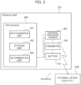
FIG. 2 , the sensor unit SU includes an internal pressure sensor SN that detects internal pressure (air pressure) of thetire 10, atransmitter 150 that transmits detection data at each fixed detection period (for example, 12 sec, 30 sec, 60 sec, or the like) to an external device (in-vehicle device (ECU) or the like), aprocessor 100, and abattery 151 that feeds the internal pressure sensor SN, theprocessor 100, and thetransmitter 150. - By providing the
processor 100 in the sensor unit SU, it is possible to determine a state in which air pressure has decreased, in a manner that is well-balanced with processing efficiency without increasing the frequency of transmitting data for which power consumption is high. - The
processor 100 is provided with astorage unit 102 configured of a flash memory or the like that stores newly acquired air pressure data P(0), and air pressure data P(1) to P(N) acquired 1 to N periods prior to the air pressure data P(0) (where N is a natural number of 2 or more). - Note that "N" in P (N) can be 3 to 5. It is thereby possible to achieve balance between handling a gradual leak in air pressure and processing efficiency.
- In addition, the
processor 100 is provided with adetermination unit 103 configured of a CPU or the like that determines a state in which air pressure has decreased, on the basis of the air pressure data. - Furthermore, the
transmitter 150 transmits the determination result of thedetermination unit 103 to anexternal device 250 such as an ECU, via a communication line N1. - Here, the
determination unit 103 compares each piece of the air pressure data P(1) to P(n) (where n is a natural number from 1 to N) with the air pressure data P(0) to calculate decrease values. - Next, the decrease values are compared with a preset first threshold value th1, and when at least one decrease value is greater than or equal to the first threshold value th1, it is determined that the tire air pressure is decreasing.
- It is thereby possible to accurately detect a decrease in air pressure even when the tire air pressure detection period is short or when there is a slow leak in which the rate of decrease in air pressure is gradual.
- Note that an example of determination processing that realizes the aforementioned processing is described hereinafter.
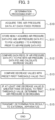
- The processing procedure for the determination processing (part 1) executed by the tire air pressure monitoring system S1a will be described with reference to the flowchart illustrated in
FIG. 3 . - When this processing is started, in step S10, tire air pressure data is acquired at each fixed detection period, and the processing moves to step S11.
- In step S11, newly acquired air pressure data P(0) and air pressure data P(1) to P(N) acquired 1 to N periods prior to the air pressure data P(0) (where N is a natural number of 2 or more) are stored by the
storage unit 102, and the processing moves to step S12. - In step S12, each piece of the air pressure data P(1) to P(n) (where n is a natural number from 1 to N) is compared with the air pressure data P(0) to calculate decrease values (for example, P(0) - P(1) and the like), and the processing moves to step S13.
- In step S13, a comparison is made with a preset first threshold value (th1), and the processing moves to step S14.
- Here, the first threshold value th1 is a threshold value for an LSB difference of the sensor that is considered to have a significant difference, taking into account errors of a sensor element constituting the internal pressure sensor SN. Furthermore, it is understood that when there is a decrease greater than or equal to the first threshold value th1, a sudden decrease in internal pressure can be determined.
- The first threshold value th1 depends on the measurement period, and can be 3 LSB (approximately 3 to 10 kPa) in 30 sec or less, or 4 LSB (approximately 5 to 15 kPa) in 60 sec, for example.
- In step S14, if at least one decrease value is greater than or equal to the first threshold value (th1) (in other words, for example, if P(0) - P(1) ≥ th1 or the like), it is determined that the tire air pressure is decreasing, and the processing moves to step S15.
- In step S15, the determination result is transmitted to the external apparatus (ECU or the like) 250, and the processing ends.
- It is thereby possible to accurately detect a decrease in air pressure even when the tire air pressure detection period is short or when there is a slow leak in which the rate of decrease in air pressure is gradual.
- A tire air pressure monitoring system S1b according to a second embodiment of the present invention will be described with reference to
FIGS. 1 ,2 ,4A ,4B , and5 . - Here, the functional configuration and the like of the tire air pressure monitoring system S1b according to the second embodiment are the same as those of the tire air pressure monitoring system S1a according to the first embodiment, and therefore duplicate descriptions are omitted.
- In the tire air pressure monitoring system S1b, in a case where the
determination unit 103 has determined that the tire air pressure is decreasing according to a decrease value between air pressure data P(k) (where k is a natural number from 1 to N) and the air pressure data P(0), when all pieces of the air pressure data P(k + 1) to P(N) are greater than the sum of the air pressure data P(0) and a preset second threshold value, it is determined that the tire air pressure is decreasing. - It thereby becomes possible to suppress the effect of a temporary decrease in pressure such as when the tire has ridden up a curb, and more accurately detect a decrease in air pressure.
- Furthermore, in a case where the
determination unit 103 has determined that the tire air pressure is decreasing according to a decrease value between air pressure data P(k) and the air pressure data P(0), with regard to hypothetical air pressure data P' when it is assumed that air pressure has decreased by a certain proportion from the air pressure data P(k) to P(0), when air pressure data P(k - 1) to P(1) and the hypothetical air pressure data P'(k - 1) to P'(1) are compared in the same period and all are within a certain range, it can be determined that the tire air pressure is decreasing. - In this case, it becomes possible to prevent erroneous determination, and more accurately detect a decrease in air pressure.
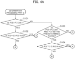
- The processing procedure for the determination processing (part 2) executed by the tire air pressure monitoring system S1b will be described with reference to the flowcharts illustrated in
FIGS. 4A and4B . - This determination processing, in addition to detecting a decrease in air pressure such as when there is a gradual leak in air pressure, makes it possible to more reliably provide notification (warning) of a decrease in air pressure by suppressing the effect of a temporary decrease in pressure such as when the tire has ridden up a curb.
- More specifically, when determining a state in which air pressure has decreased, in a case where the tire air pressure is decreasing according to a decrease value between air pressure data P(k) (where k is a natural number from 1 to N) and the air pressure data P(0), and all pieces of air pressure data P(k + 1) to P(N) are greater than the sum of the air pressure data P(0) and the preset second threshold value (th2), it is determined that the tire air pressure is decreasing.
- When this processing is started, in step S101, it is determined whether or not P(0) - P(1) ≥ th1.
- More specifically, the same processing as that in steps S10 to S15 in the aforementioned determination processing (part 1) is executed.
- Then, if it is determined that the air pressure is decreasing (if "Yes"), the processing moves to S102.
- In step S102, it is determined whether or not P(2 to 5) > P(0) + th2.
- Here, the second threshold value th2 is an upper limit for errors of the sensor element constituting the internal pressure sensor SN, and can be a value that is approximately twice the error LSB relative to the actual value (in other words, the maximum difference LSB between measurement samples when there is no change in pressure).
- Note that the second threshold value th2 can be approximately 5 to 10 kPa, for example.
- Then, if the determination result of step S102 is "No", the processing moves to step S111, and the processing ends without a warning being provided.
- Furthermore, if the determination result is "Yes", the processing moves to step S110, a warning is provided that there has been a sudden decrease in tire pressure due to the tire riding up a curb or the like, and the processing ends.
- However, if "No" is determined in step S101, the processing moves to step S103.
- In step S103, it is determined whether or not P(0) - P(2) ≥ th1 and P(1) is within a predetermined range.
- Here, P(0) - P(2) ≥ th1 refers to a case such as being in the range R1 (>th1) in the graph (vertical axis: LSB, horizontal axis: measurement period) illustrated in
FIG. 5(a) , for example. - Furthermore, P(1) being within a predetermined range refers to a case such as P(1) being within the range R2 in the graph illustrated in
FIG. 5(a) , for example. - Then, if "Yes" is determined in step S103, the processing moves to step S104.
- In step S104, it is determined whether or not P(3 to 5) > P(0) + th2.
- If the determination result is "No", the processing moves to step S111, and the processing ends without a warning being provided.
- Furthermore, if the determination result is "Yes", the processing moves to step S110, a warning is provided that there has been a sudden decrease in tire pressure due to the tire riding up a curb or the like, and the processing ends.
- However, if "No" is determined in step S103, the processing moves to step S105.
- In step S105, it is determined whether or not P(0) - P(3) ≥ th1 and P(1, 2) are within a predetermined range.
- Here, P(0) - P(3) ≥ th1 refers to a case such as being within the range R4 in the graph (vertical axis: LSB, horizontal axis: measurement period) illustrated in
FIG. 5(b) , for example. - Furthermore, P(1, 2) being within a predetermined range refers to a case such as P(1, 2) being within the range R8 or R7 in the graph illustrated in
FIG. 5(b) , for example. - Then, if "Yes" is determined in step S105, the processing moves to step S106.
- In step S106, it is determined whether or not P(4, 5) > P(0) + th2.
- If the determination result is "No", the processing moves to step S111, and the processing ends without a warning being provided.
- Furthermore, if the determination result is "Yes", the processing moves to step S110, a warning is provided that there has been a sudden decrease in tire pressure due to the tire riding up a curb or the like, and the processing ends.
- However, if "No" is determined in step S105, the processing moves to step S107.
- In step S107, it is determined whether or not P(0) - P(4) ≥ th1 and P(1 to 3) are within a predetermined range.
- Here, P(0) - P(4) ≥ th1 refers to a case such as being within the range R4 in the graph illustrated in
FIG. 5(b) , for example. - Furthermore, P(1 to 3) being within a predetermined range refers to a case such as P(1 to 3) being within the ranges R6 to R8 in the graph illustrated in
FIG. 5(b) , for example. - Then, if the determination result in step S107 is "Yes", the processing moves to step S108.
- In step S108, it is determined whether or not P(5) > P(0) + th2.
- If the determination result is "No", the processing moves to step S111, and the processing ends without a warning being provided.
- Furthermore, if the determination result is "Yes", the processing moves to step S110, a warning is provided that there has been a sudden decrease in tire pressure due to the tire riding up a curb or the like, and the processing ends.
- However, if "No" is determined in step S107, the processing moves to step S109.
- In step S109, it is determined whether or not P(0) - P(5) ≥ th1 and P(1 to 4) are within a predetermined range.
- Here, P(0) - P(5) ≥ th1 refers to a case such as being within the range R4 in the graph illustrated in
FIG. 5(b) , for example. - Furthermore, P(1 to 4) being within a predetermined range refers to a case such as P(1 to 4) being within the ranges R5 to R8 in the graph illustrated in
FIG. 5(b) , for example. - Then, if the determination result is "No", the processing moves to step S111, and the processing ends without a warning being provided.
- Furthermore, if the determination result is "Yes", the processing moves to step S110, a warning is provided that there has been a sudden decrease in tire pressure due to the tire riding up a curb or the like, and the processing ends.
- As described above, according to this processing, it is possible to detect a decrease in pressure even when there is a gradual leak in the air pressure of the
tire 10. - Furthermore, it becomes possible to suppress the effect of a temporary decrease in pressure such as when the
tire 10 has ridden up a curb, and more accurately detect a decrease in air pressure. - Furthermore, there is also the merit that it becomes possible to prevent erroneous determinations, and more accurately detect a decrease in air pressure.
- In addition, it is also possible to obtain the effect of it becoming possible to accurately detect a decrease in air pressure even when the tire air pressure detection period is short or when there is a slow leak in which the rate of decrease in air pressure is gradual.
- The processing procedure for the determination processing (part 3) executed by the tire air pressure monitoring system S1a (S1b) will be described with reference to the flowchart illustrated in
FIG. 6 . - When this processing is started, in step S201, it is determined whether or not P(0) - P(1) ≥ th3. Here, P(0) is newly acquired air pressure data, P(1) is air pressure data acquired one period before, and th3 is a preset third threshold value.
- The third threshold value th3 is a threshold value for an LSB difference of the internal pressure sensor SN at which a sudden decrease will surely occur even when the tire has ridden up a curb or the like. Furthermore, it is understood that when there is a decrease greater than or equal to the third threshold value th3, a sudden decrease in internal pressure can be determined.
- The third threshold value th3 can be approximately 10 to 30 kPa, for example.
- Then, if the determination result is "Yes", the processing moves to step S202. In step S202, a warning such as "The tire pressure is decreasing. Please perform tire maintenance." is notified to the driver or the like, and the processing ends.
- It thereby becomes possible to more reliably provide notification of a decrease in tire air pressure. In particular, it becomes possible to accurately detect and provide notification of a decrease in air pressure even when the tire air pressure detection period is short or when there is a slow leak in which the rate of decrease in air pressure is gradual.
- However, if "No" is determined in step S201, the processing moves to step S203, and the processing ends without a warning being provided.
- It is thereby possible to detect and provide notification (warning) of a
burst tire 10 or the like. - Note that the
determination unit 103 illustrated inFIG. 2 may be implemented such that the air pressure data P(1) and P(0) are compared and a decrease values is calculated, the decrease value is compared with the third threshold value th3, and it is determined that the tire air pressure is decreasing when the decrease value is greater than or equal to the third threshold value th3. - It thereby becomes possible to detect, at an early stage, a decrease in pressure that is greater than or equal to a certain threshold value such as that of a burst tire.
- As described above, the tire air pressure monitoring program in which determination processing is executed can have: a step of acquiring tire air pressure data at each fixed detection period; a step of storing newly acquired air pressure data P(0), and air pressure data P(1) to P(N) that is acquired 1 to N periods prior to the air pressure data P(0) (where N is a natural number of 2 or more); a step of determining a state in which air pressure has decreased, on the basis of the air pressure data; and a step of transmitting a determination result to the external device (ECU or the like) 250.
- Also, in the step of determining a state in which air pressure has decreased, it is possible to compare each piece of air pressure data P(1) to P(n) (where n is a natural number from 1 to N) with the air pressure data P(0) to calculate decrease values, compare the decrease values with the preset first threshold value th1, and determine that the tire air pressure is decreasing when at least one decrease value is greater than or equal to the first threshold value th1.
- It thereby becomes possible to accurately detect a decrease in air pressure even when the tire air pressure detection period is short or when there is a slow leak in which the rate of decrease in air pressure is gradual.
- Furthermore, a tire air pressure monitoring program according to another configuration can have: a step of acquiring tire air pressure data at each fixed detection period; a step of storing newly acquired air pressure data P(0), and air pressure data P(1) to P(N) acquired 1 to N periods prior to the air pressure data P(0) (where N is a natural number of 2 or more); a step of determining a state in which air pressure has decreased, on the basis of the air pressure data; and a step of transmitting a determination result to the external device (ECU or the like) 250.
- Also, in the step of determining a state in which air pressure has decreased, when it is determined that the tire air pressure is decreasing according to a decrease value between air pressure data P(k) (where k is a natural number from 1 to N) and the air pressure data P(0), and all pieces of air pressure data P(k + 1) to P(N) are greater than the sum of the air pressure data P(0) and the preset second threshold value th2, it can be determined that the tire air pressure is decreasing.
- It thereby becomes possible to suppress the effect of a temporary decrease in pressure such as when the
tire 10 has ridden up a curb, and more accurately detect a decrease in air pressure. - Furthermore, the step of determining a state in which air pressure has decreased may be implemented such that, in a case where it is determined that the tire air pressure is decreasing according to a decrease value between air pressure data P(k) and the air pressure data P(0), with regard to hypothetical air pressure data P' when it is assumed that air pressure has decreased by a certain proportion from the air pressure data P(k) to P(0), when air pressure data P(k - 1) to P(1) and the hypothetical air pressure data P'(k - 1) to P' (1) are compared in the same period and all are within a certain range, it is determined that the tire air pressure is decreasing.
- It thereby becomes possible to prevent erroneous determination, and more accurately detect a decrease in air pressure.
- Furthermore the rate of the detection period may be changed. A decrease in pressure can thereby be detected at an early stage according to the situation.
- Furthermore, the value of P(0) may be copied to P(1) to P(N) when the detection period changes. This can prevent an erroneous determination by resetting a stored value.
- Furthermore, the second threshold value th2 may be changed according to the detection period.
- A tire air pressure monitoring system S1c according to a modified example will be described with reference to
FIG. 7 . -
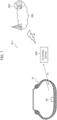
FIG. 7 is a schematic configuration diagram illustrating the tire air pressure monitoring system S1c according to the modified example. - As illustrated in
FIG. 7 , in the tire air pressure monitoring system S1c, a configuration is adopted in which the external device (ECU or the like) 250 mounted in each vehicle communicates wirelessly with the sensor unit SU attached to thepneumatic tire 10 via the wireless line N1, and also communicates with anexternal cloud system 300 via a wireless line N2. Furthermore, thecloud system 300 is connected to amanagement server 200. - The external device of each vehicle then transmits temperature data, internal pressure data, and the like acquired from the sensor unit SU to the
cloud system 300. - Furthermore, the sensor unit SU may be configured to communicate directly with the
external cloud system 300. - It is thereby possible for the
cloud system 300 or themanagement server 200 to perform some or all of the aforementioned determination processing executed by the sensor unit SU. It is thereby possible to reduce the processing load of the sensor unit SU. - The tire air pressure monitoring system and tire air pressure monitoring program of the present invention have been described above based on the illustrated embodiments; however, the present invention is not limited thereto, and the configuration of each part can be replaced with any other configurations having equivalent functions.
- For example, some of the processing functions of the sensor unit SU in the embodiments herein may be mounted within the
external device 250. -
- S1a, S1b, S1c
- Tire air pressure monitoring system
- SU
- Sensor unit
- SN
- Internal pressure sensor
- 100
- Processor
- 101
- Data acquisition unit
- 102
- Storage unit
- 103
- Determination unit
- 150
- Transmitter
- 151
- Battery
- 250
- External device
Claims (6)
- A tire air pressure monitoring system comprising:a data acquisition unit that acquires tire air pressure data at each fixed detection period;a storage unit that stores newly acquired air pressure data P(0), and air pressure data P(1) to P(N) acquired 1 to N periods prior to the air pressure data P(0) (where N is a natural number of 2 or more);a determination unit that determines a state in which air pressure has decreased, on the basis of the air pressure data; anda communication unit that transmits a determination result of the determination unit to an external device,wherein the determination unit compares each piece of the air pressure data P(1) to P(n) (where n is a natural number from 1 to N) with the air pressure data P(0) to calculate decrease values, compares the decrease values with a preset first threshold value, and determines that tire air pressure is decreasing when at least one decrease value is greater than or equal to the first threshold value.
- A tire air pressure monitoring system comprising:a data acquisition unit that acquires tire air pressure data at each fixed detection period;a storage unit that stores newly acquired air pressure data P(0), and data P(1) to P(N) acquired 1 to N periods prior to the air pressure data P(0) (where N is a natural number of 2 or more);a determination unit that determines a state in which air pressure has decreased, on the basis of the air pressure data; anda communication unit that transmits a determination result of the determination unit to an external device,wherein, in a case where the determination unit has determined that tire air pressure is decreasing according to a decrease value between air pressure data P(k) (where k is a natural number from 1 to N) and the air pressure data P(0), when all pieces of the air pressure data P(k + 1) to P(N) are greater than a sum of the air pressure data P(0) and a preset second threshold value, it is determined that the tire air pressure is decreasing.
- The tire air pressure monitoring system according to claim 1,
wherein, in a case where the determination unit has determined that the tire air pressure is decreasing according to a decrease value between air pressure data P(k) and the air pressure data P(0), with regard to hypothetical air pressure data P' when it is assumed that air pressure has decreased by a certain proportion from the air pressure data P(k) to P(0), when air pressure data P(k - 1) to P(1) and the hypothetical air pressure data P' (k - 1) to P' (1) are compared in a same period and all are within a certain range, it is determined that the tire air pressure is decreasing. - A tire air pressure monitoring program executed by a computer provided in a tire air pressure monitoring system, the program comprising:a step of acquiring tire air pressure data at each fixed detection period;a step of storing newly acquired air pressure data P(0), and air pressure data P(1) to P(N) acquired 1 to N periods prior to the air pressure data P(0) (where N is a natural number of 2 or more);a step of determining a state in which air pressure has decreased, on the basis of the air pressure data; anda step of transmitting a determination result to an external device,wherein, in the step of determining the state in which air pressure has decreased, each piece of the air pressure data P(1) to P(n) (where n is a natural number from 1 to N) is compared with the air pressure data P(0) to calculate decrease values, the decrease values are compared with a preset first threshold value, and it is determined that tire air pressure is decreasing when at least one decrease value is greater than or equal to the first threshold value.
- A tire air pressure monitoring program executed by a computer provided in a tire air pressure monitoring system, the program comprising:a step of acquiring tire air pressure data at each fixed detection period;a step of storing newly acquired air pressure data P(0), and air pressure data P(1) to P(N) acquired 1 to N periods prior to the air pressure data P(0) (where N is a natural number of 2 or more);a step of determining a state in which air pressure has decreased, on the basis of the air pressure data; anda step of transmitting a determination result to an external device,wherein, in the step of determining the state in which air pressure has decreased, in a case where it is determined that tire air pressure is decreasing according to a decrease value between air pressure data P(k) (where k is a natural number from 1 to N) and the air pressure data P(0), when all pieces of the air pressure data P(k + 1) to P(N) are greater than a sum of the air pressure data P(0) and a preset second threshold value, it is determined that the tire air pressure is decreasing.
- The tire air pressure monitoring program according to claim 4,
wherein, in the step of determining the state in which air pressure has decreased, in a case where it is determined that the tire air pressure is decreasing according to a decrease value between air pressure data P(k) and the air pressure data P(0), with regard to hypothetical air pressure data P' when it is assumed that air pressure has decreased by a certain proportion from the air pressure data P(k) to P(0), when air pressure data P(k - 1) to P(1) and the hypothetical air pressure data P'(k - 1) to P'(1) are compared in a same period and all are within a certain range, it is determined that the tire air pressure is decreasing.
Applications Claiming Priority (2)
| Application Number | Priority Date | Filing Date | Title |
|---|---|---|---|
| JP2020174380A JP7461271B2 (en) | 2020-10-16 | 2020-10-16 | Tire pressure monitoring system and tire pressure monitoring program |
| PCT/JP2021/037098 WO2022080221A1 (en) | 2020-10-16 | 2021-10-07 | Tire pneumatic pressure monitoring system and tire pneumatic pressure monitoring program |
Publications (3)
| Publication Number | Publication Date |
|---|---|
| EP4230442A1 true EP4230442A1 (en) | 2023-08-23 |
| EP4230442A4 EP4230442A4 (en) | 2024-03-27 |
| EP4230442B1 EP4230442B1 (en) | 2026-05-20 |
Family
ID=81208056
Family Applications (1)
| Application Number | Title | Priority Date | Filing Date |
|---|---|---|---|
| EP21879961.7A Active EP4230442B1 (en) | 2020-10-16 | 2021-10-07 | TIRE PRESSURE MONITORING SYSTEM AND TIRE PRESSURE MONITORING PROGRAM |
Country Status (4)
| Country | Link |
|---|---|
| US (1) | US12385795B2 (en) |
| EP (1) | EP4230442B1 (en) |
| JP (1) | JP7461271B2 (en) |
| WO (1) | WO2022080221A1 (en) |
Families Citing this family (1)
| Publication number | Priority date | Publication date | Assignee | Title |
|---|---|---|---|---|
| JP2024142712A (en) | 2023-03-30 | 2024-10-11 | 住友ゴム工業株式会社 | Tire Pressure Monitoring Device |
Family Cites Families (17)
| Publication number | Priority date | Publication date | Assignee | Title |
|---|---|---|---|---|
| JP2000099869A (en) * | 1998-09-21 | 2000-04-07 | Toyota Motor Corp | Tire pressure monitor |
| EP1092570B1 (en) * | 1999-10-12 | 2005-09-14 | Pacific Industrial Co., Ltd. | Transmitter and transmitting method of tire air pressure monitoring apparatus |
| FR2874539B1 (en) | 2004-09-01 | 2006-10-13 | Siemens Vdo Automotive Sas | METHOD AND DEVICE FOR FILTERING INFORMATION EMITTED BY A PRESSURE SENSOR MOUNTED ON A WHEEL OF A VEHICLE |
| JP2006168457A (en) * | 2004-12-14 | 2006-06-29 | Mitsubishi Motors Corp | Tire pressure monitoring device |
| EP1798077B1 (en) * | 2005-12-16 | 2014-05-07 | Sumitomo Rubber Industries, Ltd. | Apparatus, method and program for alarming decrease in tire air-pressure |
| JP2008013145A (en) * | 2006-07-10 | 2008-01-24 | Calsonic Kansei Corp | Tire air pressure monitoring device |
| JP4536089B2 (en) * | 2007-07-20 | 2010-09-01 | 住友ゴム工業株式会社 | Tire pressure drop detection method and apparatus, and tire decompression determination program |
| JP4964325B2 (en) * | 2010-04-23 | 2012-06-27 | 住友ゴム工業株式会社 | Tire pressure drop detection device, method and program |
| JP5204861B2 (en) * | 2011-02-02 | 2013-06-05 | 住友ゴム工業株式会社 | Tire pressure drop detection method, apparatus and program |
| JP5429211B2 (en) * | 2011-02-21 | 2014-02-26 | 株式会社デンソー | Tire pressure detector |
| JP2012171463A (en) | 2011-02-21 | 2012-09-10 | Denso Corp | Tire air pressure detector |
| DE102013219849A1 (en) * | 2013-10-01 | 2015-04-02 | Aktiebolaget Skf | Apparatus and method for detecting a pressure change in a tire |
| WO2016103453A1 (en) * | 2014-12-26 | 2016-06-30 | 横浜ゴム株式会社 | Tire state monitoring system |
| JP2017087941A (en) * | 2015-11-09 | 2017-05-25 | 株式会社デンソー | Tire pressure detection system |
| JP6470217B2 (en) * | 2016-03-24 | 2019-02-13 | 株式会社日立ビルシステム | Anti-slip device for passenger conveyor |
| JP7405732B2 (en) * | 2020-12-07 | 2023-12-26 | 株式会社ブリヂストン | Tire pressure monitoring device, tire pressure monitoring method and monitoring program |
| JP2024142712A (en) * | 2023-03-30 | 2024-10-11 | 住友ゴム工業株式会社 | Tire Pressure Monitoring Device |
-
2020
- 2020-10-16 JP JP2020174380A patent/JP7461271B2/en active Active
-
2021
- 2021-10-07 WO PCT/JP2021/037098 patent/WO2022080221A1/en not_active Ceased
- 2021-10-07 US US18/031,694 patent/US12385795B2/en active Active
- 2021-10-07 EP EP21879961.7A patent/EP4230442B1/en active Active
Also Published As
| Publication number | Publication date |
|---|---|
| US12385795B2 (en) | 2025-08-12 |
| US20240019328A1 (en) | 2024-01-18 |
| JP7461271B2 (en) | 2024-04-03 |
| JP2022065730A (en) | 2022-04-28 |
| EP4230442B1 (en) | 2026-05-20 |
| WO2022080221A1 (en) | 2022-04-21 |
| EP4230442A4 (en) | 2024-03-27 |
Similar Documents
| Publication | Publication Date | Title |
|---|---|---|
| CN106965632B (en) | Tire monitoring devices and systems for use with onboard stability control systems | |
| EP2740640B1 (en) | Tire slip angle estimation system and method | |
| US12583267B2 (en) | Tire state monitoring system and tire state monitoring method | |
| JP7405732B2 (en) | Tire pressure monitoring device, tire pressure monitoring method and monitoring program | |
| US12005747B2 (en) | Tire mounting state detection system, tire mounting state detection method, and tire mounting state detection program | |
| US12385795B2 (en) | Tire air pressure monitoring system and tire air pressure monitoring program | |
| US20160176245A1 (en) | Apparatus and method for changing tpms sensor message preamble based upon mode | |
| KR101216448B1 (en) | Method and device for filtering information emitted by a pressure sensor mounted on a wheel of a vehicle | |
| US7432801B2 (en) | System and method for detecting a rapid leak from a tire | |
| US7668695B2 (en) | Sensor malfunction determination device and sensor malfunction determination method | |
| JP2021195091A (en) | Tire air pressure monitoring system and tire air pressure monitoring program | |
| CN110799361B (en) | Tire installation position detection system, tire installation position detection method, and tire installation position detection program | |
| CN119974839A (en) | A multifunctional tire monitoring method and system for tire parameter perception | |
| JP2023067143A (en) | Detection device, detection system, detection method and detection program | |
| US12535386B2 (en) | Tire wear condition prediction system, tire wear condition prediction program and tire wear condition prediction method | |
| CN116039297A (en) | Tire pressure monitoring method and system | |
| KR102301098B1 (en) | System and method for determining tire pressure monitoring system sensor location | |
| WO2022219897A1 (en) | Tire pneumatic pressure monitoring system, tire pneumatic pressure monitoring program, and tire pneumatic pressure monitoring method | |
| CN120840298A (en) | Vehicle tire pressure monitoring method, system and vehicle | |
| CN121912743A (en) | Sensor unit for detecting rapid tire pressure loss | |
| KR101549085B1 (en) | System and method for detecting error of tire sensor | |
| JP2025047816A (en) | Leakage monitoring device, leakage monitoring method and leakage monitoring system | |
| CN105620208A (en) | Traffic safety monitoring system and method | |
| KR20070060913A (en) | Tire pressure monitoring device |
Legal Events
| Date | Code | Title | Description |
|---|---|---|---|
| STAA | Information on the status of an ep patent application or granted ep patent |
Free format text: STATUS: THE INTERNATIONAL PUBLICATION HAS BEEN MADE |
|
| PUAI | Public reference made under article 153(3) epc to a published international application that has entered the european phase |
Free format text: ORIGINAL CODE: 0009012 |
|
| STAA | Information on the status of an ep patent application or granted ep patent |
Free format text: STATUS: REQUEST FOR EXAMINATION WAS MADE |
|
| 17P | Request for examination filed |
Effective date: 20230504 |
|
| AK | Designated contracting states |
Kind code of ref document: A1 Designated state(s): AL AT BE BG CH CY CZ DE DK EE ES FI FR GB GR HR HU IE IS IT LI LT LU LV MC MK MT NL NO PL PT RO RS SE SI SK SM TR |
|
| DAV | Request for validation of the european patent (deleted) | ||
| DAX | Request for extension of the european patent (deleted) | ||
| A4 | Supplementary search report drawn up and despatched |
Effective date: 20240223 |
|
| RIC1 | Information provided on ipc code assigned before grant |
Ipc: B60C 23/04 20060101AFI20240219BHEP |
|
| GRAP | Despatch of communication of intention to grant a patent |
Free format text: ORIGINAL CODE: EPIDOSNIGR1 |
|
| STAA | Information on the status of an ep patent application or granted ep patent |
Free format text: STATUS: GRANT OF PATENT IS INTENDED |
|
| GRAS | Grant fee paid |
Free format text: ORIGINAL CODE: EPIDOSNIGR3 |
|
| GRAA | (expected) grant |
Free format text: ORIGINAL CODE: 0009210 |
|
| STAA | Information on the status of an ep patent application or granted ep patent |
Free format text: STATUS: THE PATENT HAS BEEN GRANTED |
|
| INTG | Intention to grant announced |
Effective date: 20260319 |
|
| P01 | Opt-out of the competence of the unified patent court (upc) registered |
Free format text: CASE NUMBER: UPC_APP_0011959_4230442/2026 Effective date: 20260407 |
|
| AK | Designated contracting states |
Kind code of ref document: B1 Designated state(s): AL AT BE BG CH CY CZ DE DK EE ES FI FR GB GR HR HU IE IS IT LI LT LU LV MC MK MT NL NO PL PT RO RS SE SI SK SM TR |
|
| P01 | Opt-out of the competence of the unified patent court (upc) registered |
Free format text: CASE NUMBER: UPC_APP_0011959_4230442/2026 Effective date: 20260407 |
|
| REG | Reference to a national code |
Ref country code: CH Ref legal event code: F10 Free format text: ST27 STATUS EVENT CODE: U-0-0-F10-F00 (AS PROVIDED BY THE NATIONAL OFFICE) Effective date: 20260520 Ref country code: GB Ref legal event code: FG4D |
|
| REG | Reference to a national code |
Ref country code: DE Ref legal event code: R096 Ref document number: 602021054725 Country of ref document: DE |