EP4230340A1 - Clamping device for laser processing machine - Google Patents
Clamping device for laser processing machine Download PDFInfo
- Publication number
- EP4230340A1 EP4230340A1 EP22157320.7A EP22157320A EP4230340A1 EP 4230340 A1 EP4230340 A1 EP 4230340A1 EP 22157320 A EP22157320 A EP 22157320A EP 4230340 A1 EP4230340 A1 EP 4230340A1
- Authority
- EP
- European Patent Office
- Prior art keywords
- clamping
- clamping members
- workpiece
- machine according
- machine
- Prior art date
- Legal status (The legal status is an assumption and is not a legal conclusion. Google has not performed a legal analysis and makes no representation as to the accuracy of the status listed.)
- Withdrawn
Links
- 238000012545 processing Methods 0.000 title claims abstract description 18
- 238000012937 correction Methods 0.000 claims description 7
- 230000000903 blocking effect Effects 0.000 claims description 6
- 238000005520 cutting process Methods 0.000 claims description 5
- 238000003698 laser cutting Methods 0.000 claims description 3
- 238000003466 welding Methods 0.000 description 5
- 230000005855 radiation Effects 0.000 description 4
- 238000003825 pressing Methods 0.000 description 3
- 238000013519 translation Methods 0.000 description 3
- 230000014616 translation Effects 0.000 description 3
- 230000001154 acute effect Effects 0.000 description 2
- 238000013459 approach Methods 0.000 description 1
- 230000009286 beneficial effect Effects 0.000 description 1
- 230000001419 dependent effect Effects 0.000 description 1
- 239000013013 elastic material Substances 0.000 description 1
- 238000004519 manufacturing process Methods 0.000 description 1
- 230000009347 mechanical transmission Effects 0.000 description 1
- 238000000034 method Methods 0.000 description 1
- 230000003287 optical effect Effects 0.000 description 1
Images


Classifications
-
- B—PERFORMING OPERATIONS; TRANSPORTING
- B23—MACHINE TOOLS; METAL-WORKING NOT OTHERWISE PROVIDED FOR
- B23K—SOLDERING OR UNSOLDERING; WELDING; CLADDING OR PLATING BY SOLDERING OR WELDING; CUTTING BY APPLYING HEAT LOCALLY, e.g. FLAME CUTTING; WORKING BY LASER BEAM
- B23K26/00—Working by laser beam, e.g. welding, cutting or boring
- B23K26/36—Removing material
- B23K26/38—Removing material by boring or cutting
-
- B—PERFORMING OPERATIONS; TRANSPORTING
- B23—MACHINE TOOLS; METAL-WORKING NOT OTHERWISE PROVIDED FOR
- B23K—SOLDERING OR UNSOLDERING; WELDING; CLADDING OR PLATING BY SOLDERING OR WELDING; CUTTING BY APPLYING HEAT LOCALLY, e.g. FLAME CUTTING; WORKING BY LASER BEAM
- B23K37/00—Auxiliary devices or processes, not specially adapted for a procedure covered by only one of the other main groups of this subclass
- B23K37/04—Auxiliary devices or processes, not specially adapted for a procedure covered by only one of the other main groups of this subclass for holding or positioning work
- B23K37/053—Auxiliary devices or processes, not specially adapted for a procedure covered by only one of the other main groups of this subclass for holding or positioning work aligning cylindrical work; Clamping devices therefor
- B23K37/0533—External pipe alignment clamps
-
- B—PERFORMING OPERATIONS; TRANSPORTING
- B23—MACHINE TOOLS; METAL-WORKING NOT OTHERWISE PROVIDED FOR
- B23K—SOLDERING OR UNSOLDERING; WELDING; CLADDING OR PLATING BY SOLDERING OR WELDING; CUTTING BY APPLYING HEAT LOCALLY, e.g. FLAME CUTTING; WORKING BY LASER BEAM
- B23K2101/00—Articles made by soldering, welding or cutting
- B23K2101/04—Tubular or hollow articles
- B23K2101/06—Tubes
-
- B—PERFORMING OPERATIONS; TRANSPORTING
- B23—MACHINE TOOLS; METAL-WORKING NOT OTHERWISE PROVIDED FOR
- B23K—SOLDERING OR UNSOLDERING; WELDING; CLADDING OR PLATING BY SOLDERING OR WELDING; CUTTING BY APPLYING HEAT LOCALLY, e.g. FLAME CUTTING; WORKING BY LASER BEAM
- B23K2101/00—Articles made by soldering, welding or cutting
- B23K2101/28—Beams
Definitions
- the invention is in the field of laser processing machines for working elongate workpieces, such as tubes or other profiled bodies.
- laser processing machines include laser cutting machines and laser beam welding machines.
- CN112658467A and CN112658468A propose spring actuated pressure plates that adjust the orientation or lateral position, respectively, of non-round workpieces before the auto centering jaws adjust their position.
- CN112658467A and in CN112658468A has the disadvantages that the shape of the jaws needs to be adapted to the shape of the workpiece to at least some extent, and that a blocking situation may result if the lateral centering or orientation, respectively, is not appropriate.
- the jaws are used to fix an elliptical tube, the contact between the jaws and the tube is constrained to two contact lines with a correspondingly high local contact pressure.
- possible problems may arise if the workpiece is not perfectly laterally aligned and oriented when the jaws are closed upon it. When it touches the jaws in two spots, it can get stuck and block the complete closing of the jaws.
- the laser processing machine is to overcome drawbacks of prior art machines, and is especially suitable for processing elongate workpieces, especially tubes, of different cross sections.
- An elongate workpiece is a workpiece whose extension in one dimension (along an axial direction) is much greater, for example by at least a factor 4, than the extensions in dimensions orthogonal thereto.
- the workpiece may be a tube or other profile having, at least in regions, a constant profile along the axial direction.
- laser processing machine comprises a fixture, the fixture comprising a pair of first clamping members and a pair of second clamping members.
- the clamping members of each pair are movable in mutually opposite clamping directions towards each other to clamp the workpiece between clamping faces of the clamping members.
- the clamping directions of the second clamping members are transverse, especially orthogonal, to the clamping directions of the first clamping members.
- At least the first clamping members each comprise a retractable jaw, the jaw being movable relative to the respective clamping face of the clamping member to which the retractable jaw belongs.
- the laser processing machine may especially be a laser cutting machine or laser welding machine for cutting/welding tubes as the workpieces, the machine especially being equipped for cutting/welding elliptical tubes, possibly in addition to other workpieces.
- the retractable jaws may especially be pressed inwardly (radially inwardly; towards an axis), against a stop and be displaceable relative to the clamping face against a spring force.
- the retractable jaw may especially be mounted on a surface of a clamping member main body, which surface is radial and may lay orthogonally to the axis.
- the axial position of the engagement face of the retractable jaw may be offset with respect to the axial position of the clamping face.
- the retractable jaw may be guided relative to the clamping jaw main body by two parallel, rail-like guiding elements.
- the retractable jaw may comprise two grooves or slots into which dedicated studs of the main body engage, or vice versa.
- the retractable jaws may have an engagement surface that is shaped to receive an elliptic or round profile in a centering manner.
- each jaw is thus concave in the mathematical sense (with the surface being curved or flat).
- the engagement surface is centering.
- the retractable jaws may have two inclined centering portions that are at an acute angle (non-zero and less than 90°) to the plane that is normal to radial directions.
- the engagement surface can be approximately V-shaped or C-shaped or U-shaped.
- the acute angle in this may especially be between 15° and 35°, this range proving to be beneficial for accommodating elliptic profiles of different ellipticities and sizes. More in general, the angle may be between 10° and 45°, and specifically it may be between 18° and 28°.
- the clamping faces of the first clamping members and/or of the second clamping members are flat in the sense that they have an essentially constant cross section along their width (symmetry with respect to translations in the transverse direction), whereby an adjustment of the transverse position (for example by the second pair of clamping members) encounters comparably less resistance when the workpiece is being clamped (for example by the first pair of clamping members).
- the fixture further comprises a blocking system to block the retractable jaw in the retracted position.
- a blocking system may for example be used if a workpiece having a rectangular profile or other profile for which the retractable jaws are not useful, is to be fixed. It may comprise a jamming mechanism jamming the retractable jaw against the main body.
- first clamping members not only the first clamping members but also the second clamping members each comprises a retractable jaw.
- the fixture may in addition to comprising the clamping members also comprise a mechanism for moving the clamping members, for example a pneumatic drive.
- a control module of the fixture controls the movements of the clamping members.
- the control module in this may be a dedicated separate control module or may be integrated in a machine control of the entire machine or a machine module thereof.
- the control module may be equipped to first apply a first, small clamping force between the first clamping members and to maintain this first clamping force when the second clamping members close on the workpiece, so that lateral movements of the workpiece are not impeded by a too high clamping force. After the closing of the second clamping members has been effected, the control module may cause a second, higher clamping force to be applied to the first clamping members.
- the fixture may be mounted on a machine part or belong thereto, which machine part is rotatable. Especially, the fixture may belong to a rotatable mandrel.
- the laser processing machine in addition to comprising the fixture also comprises a laser source and possibly a radiation guide for guiding the radiation from the laser source to a radiation emitting laser head, wherein the machine is configured to cause radiation generated by the laser source to impinge on the workpiece fixed by the fixture.
- the laser processing machine may further comprise a sensor system to check the correct alignment of the workpiece when fixed by the fixture.
- a correction routine programmed in the machine control may apply a correction of the positioning is found to be insufficient.
- the machine may rotate the workpiece for checking the alignment/positioning and/or for correcting. Correcting the alignment/position may include the temporary release of the clamping force acting on the pair of first clamping members and/or on the pair of second clamping members and the re-applying of this clamping force(s), possibly after a rotation step and/or further position adjustment step.
- Figure 1 shows a perspective view on a mandrel comprising a fixture 1 for fixing a workpiece to a stationary or not stationary part of a laser processing machine, for example a laser tube cutting machine.
- the fixture comprises a pair of first clamping members 3, 4 and a pair of second clamping members 5, 6.
- the second clamping members 5, 6 are offset with respect to the first clamping members 3, 4 with respect to an axial direction (axis 10).
- the fixture is equipped for the clamping members of each pair to be moved towards each other in a radial direction so as to clamp a workpiece between them.
- the workpiece will mostly be an elongate workpiece, with a workpiece longitudinal axis aligned to the axis 10 of the fixture.
- the drive for moving the clamping members of each pair may be a pneumatic drive.
- the movement of the two clamping members 3, 4; 5, 6 of each pair may be coupled or may be individually controllable, whereas the pairs of clamping members function independently of each other.
- Fig. 1 also shows a Cartesian coordinate system, with the axis being parallel to the z-direction, z-directions also being called the "axial directions" in the present text.
- the entire fixture 1 may be provided on rotatable machine part or alternatively on a stationary machine part.
- the whole mandrel is rotatable.
- the coordinate system in the present text is assumed to be defined relative to the fixture, i.e., when the mandrel is rotated, so is the coordinate system.
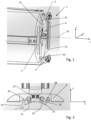
- Figure 2 shows one of the first clamping members 3.
- the first clamping member 3 has a clamping face 21, which may be structured, for example toothed and/or profiled so that the contact between the clamping face and the clamped workpiece need not be, dependent on the structure of the workpiece, a 2D-area but may be restricted to one or more contact lines or contact points. It is also possible that the clamping face comprises elastic material so that the shape adapts to some extent to the shape of the workpiece.
- the clamping face 21 may be constant with respect to translations into the transverse (x-) directions, as becomes visible for the lower clamping member 4 in Fig. 1 .
- the first clamping member 3 comprises a retractable jaw 23.
- the retractable jaw 23 is movable relative to a clamping member main body 22 (with the clamping face 21) in a radial direction. To define the possible movement direction and limits, it has two guiding slots 25 into which guiding studs 26 of the clamping member main body 22 engage.
- the guiding slots define the orientation of the retractable jaw 23 relative to the main body 22, for example together with a further guiding means, which is illustrated to be arranged between a pair of springs 27 in Fig. 2 .
- the pair of springs 27 press the retractable jaw towards radially-inward against a stop formed by one end of each guiding slots.
- the retractable jaw 23 has an engagement surface, which, similar to the clamping face 21 but independently thereof, may be structured or consist of flat surface portions.
- the engagement surface especially has two inclined centering portions 31, 32 at an angle to the plane that is orthogonal on the radial direction, the centering portions 31, 32 facing inwardly. Thereby, the engagement surface has an overall V-shape.
- the centering portions 31, 32 being straight, as shown in the depicted embodiment, other shapes of the engagement surface would be possible, for example a continuously curved shape (c-shape).
- the engagement surface by having centering portions facing each other, forms a region for any workpiece having an elliptic or round cross section as is illustrated for example in Figs. 4 and 5 described hereinafter.
- the angle formed by the two inclined centering portions 31, 32 of the engagement surface is optimized for centering elliptical profiles of different sizes and ellipticities.
- the angle ⁇ between the inclined centering portions and the plane perpendicular to the radial direction may be between 10° and 45°, especially between 15° and 35°, for example between 18° and 28°.
- Figure 3 schematically illustrates, in cross section, a workpiece 41 being an elliptic tube, the tube axis 40 extending perpendicular to the drawing plane.
- the retractable jaw 23 of the upper first clamping member 3 is shown in the extended position (no external forces acting on the clamping member 3), whereas, for illustration purposes, the retractable jaw 23 of the lower first clamping member 4 is shown in the retracted position, with no springs 27 being shown.
- the pair of first clamping members 3, 4 closes on the workpiece by being moved towards each other in opposite directions (the y-direction and the -y-direction, respectively).
- the force of the springs 27 is calibrated in the way that the retractable jaw 23 can align the elliptical profile at the first contact. This is illustrated in Figure 4 .
- the pressing force on the first clamping members 3, 4 is increased until the clamping face 21 gets into physical contact with the workpiece, and the workpiece is clamped between the first clamping members 3, 4 ( Figure 5 ).
- the pair of second clamping members 5, 6 closes on the workpiece from laterally (referring to the orientation shown in the figures), i.e., by being moved towards each other in opposite directions (the x- direction and the -x-direction, respectively), the directions of their movements being perpendicular to the movement directions of the pair of first clamping members.
- the shape of the surface of the clamping faces 21 of the first clamping members 3 ,4, for example the shape of teeth that form the clamping face 21, is made in the way that a lateral movement of the workpiece is still possible in a way that the pair of second clamping members 5, 6 can center it also with respect to lateral directions for example by the surface of the clamping faces having the mentioned property of being constant with respect to translations into the transverse (x-) directions.
- Figure 6 illustrates the fact that if a workpiece having a non-elliptic profile is fixed, the retractable jaws 23 touch the workpiece and then go to the compressed position in the way that at the end the final position of the profile is not affected by the presence of the retractable jaws ( fig 5 ). In this way, it is not necessary to replace the clamping members or remove the retractable jaws when there is a change of production.
- the first clamping members 3, 4 - or generally those clamping members that comprise a retractable jaw - may comprise an optional blocking system so as to fast block and release the retractable jaws 23 from the retracted position.
- the blocking system comprises an eccentric turning knob 29 that depending on its orientation blocks the retractable jaw 23 or releases it (release position: see for example Fig. 6 ).
- retractable jaws also on the second clamping members.
- the machine may be equipped to apply a first clamping force between the pair of first clamping members before the pair of second clamping members closes on the workpiece, and to increase the clamping force to a second clamping force thereafter.
- the workpiece is to some degree movable when the pair of second clamping members closes on it so that an adjustment of its alignment - for example of its exact lateral position and also of its orientation around the axis 10 and/or alignment with the axis - encounters less mechanical resistance.
- the pressing force of the clamping members may be applied by a pneumatic system or alternatively by an electric drive with a mechanical transmission or in any other suitable way.
- An even further optional feature of the invention includes the use of a suitable sensor system - for example including an optical sensor, such as a camera - to check the alignment of the workpiece and a correction, which for example may include a rotation of the mandrel, so as to increase the precision of the positioning.
- a control software of the machine that has the fixture may be used to interpret the data from the sensor system and to initiate, if necessary, the correction step or correction steps in a control cycle. It is, however, also possible to use a dedicated separate software tool for this.
Landscapes
- Engineering & Computer Science (AREA)
- Physics & Mathematics (AREA)
- Optics & Photonics (AREA)
- Mechanical Engineering (AREA)
- Plasma & Fusion (AREA)
- Jigs For Machine Tools (AREA)
- Laser Beam Processing (AREA)
Abstract
The disclosure concerns a laser processing machine for processing elongate workpieces, for example tubes. The machine comprises a fixture for fixing an elongate workpiece (41) relative to a machine part. The fixture has a pair of first clamping members (3, 4) and a pair of second clamping members (5, 6). The first clamping members and the second clamping members each have a clamping face (21). The clamping members of each pair are movable in mutually opposite clamping directions towards each other to clamp the workpiece between their clamping faces (21). At least the first clamping members each comprise a retractable jaw (23) that centers the workpiece, the retractable jaw (23) being movable relative to the clamping face (21).
Description
- The invention is in the field of laser processing machines for working elongate workpieces, such as tubes or other profiled bodies. Such laser processing machines include laser cutting machines and laser beam welding machines.
- If a tube or other elongate body is subject to a laser beam working step, such as for example cutting or welding, it needs to be fixed relative to the machine that works it. To this end, for example in
CN112658467A and inCN112658468A , a system with two "V"-shaped auto centering jaws is disclosed, between which the workpiece is clamped. To deal with not adjusted orientations of the workpiece,CN112658467A andCN112658468A propose spring actuated pressure plates that adjust the orientation or lateral position, respectively, of non-round workpieces before the auto centering jaws adjust their position. The approach ofCN112658467A and inCN112658468A has the disadvantages that the shape of the jaws needs to be adapted to the shape of the workpiece to at least some extent, and that a blocking situation may result if the lateral centering or orientation, respectively, is not appropriate. For example, if the jaws are used to fix an elliptical tube, the contact between the jaws and the tube is constrained to two contact lines with a correspondingly high local contact pressure. In such a setup, possible problems may arise if the workpiece is not perfectly laterally aligned and oriented when the jaws are closed upon it. When it touches the jaws in two spots, it can get stuck and block the complete closing of the jaws. - It is an object of the present invention to provide laser processing machine for laser processing elongate workpieces, the laser processing machine having a fixture for fixing the elongate workpiece relative to a machine part. The laser processing machine is to overcome drawbacks of prior art machines, and is especially suitable for processing elongate workpieces, especially tubes, of different cross sections.
- An elongate workpiece is a workpiece whose extension in one dimension (along an axial direction) is much greater, for example by at least a
factor 4, than the extensions in dimensions orthogonal thereto. In many embodiments, the workpiece may be a tube or other profile having, at least in regions, a constant profile along the axial direction. - Especially, it is an object of the invention to provide a laser processing machine having fixture suitable for fixing elliptic tubes relative to a machine part.
- According to an aspect of the invention, laser processing machine comprises a fixture, the fixture comprising a pair of first clamping members and a pair of second clamping members. The clamping members of each pair are movable in mutually opposite clamping directions towards each other to clamp the workpiece between clamping faces of the clamping members. The clamping directions of the second clamping members are transverse, especially orthogonal, to the clamping directions of the first clamping members. At least the first clamping members each comprise a retractable jaw, the jaw being movable relative to the respective clamping face of the clamping member to which the retractable jaw belongs.
- The laser processing machine may especially be a laser cutting machine or laser welding machine for cutting/welding tubes as the workpieces, the machine especially being equipped for cutting/welding elliptical tubes, possibly in addition to other workpieces.
- The retractable jaws may especially be pressed inwardly (radially inwardly; towards an axis), against a stop and be displaceable relative to the clamping face against a spring force.
- The retractable jaw may especially be mounted on a surface of a clamping member main body, which surface is radial and may lay orthogonally to the axis. Thus, the axial position of the engagement face of the retractable jaw may be offset with respect to the axial position of the clamping face. By having the retractable jaw, the clamping member thus is somewhat thicker (larger axial extension) than it could be if it did not have the retractable jaw.
- In order for the retractable jaw to have a defined and constant orientation, the retractable jaw may be guided relative to the clamping jaw main body by two parallel, rail-like guiding elements. For example, the retractable jaw may comprise two grooves or slots into which dedicated studs of the main body engage, or vice versa.
- The retractable jaws may have an engagement surface that is shaped to receive an elliptic or round profile in a centering manner.
- The engagement surface of each jaw is thus concave in the mathematical sense (with the surface being curved or flat). When the workpiece is received in the receiving region formed by the retractable jaw, it is thereby confined in the two lateral directions, whereby the engagement surface is centering.
- Especially, the retractable jaws may have two inclined centering portions that are at an acute angle (non-zero and less than 90°) to the plane that is normal to radial directions. Thus, the engagement surface can be approximately V-shaped or C-shaped or U-shaped. The acute angle in this may especially be between 15° and 35°, this range proving to be beneficial for accommodating elliptic profiles of different ellipticities and sizes. More in general, the angle may be between 10° and 45°, and specifically it may be between 18° and 28°.
- In embodiments, the clamping faces of the first clamping members and/or of the second clamping members are flat in the sense that they have an essentially constant cross section along their width (symmetry with respect to translations in the transverse direction), whereby an adjustment of the transverse position (for example by the second pair of clamping members) encounters comparably less resistance when the workpiece is being clamped (for example by the first pair of clamping members).
- In embodiments, the fixture further comprises a blocking system to block the retractable jaw in the retracted position. Such blocking system may for example be used if a workpiece having a rectangular profile or other profile for which the retractable jaws are not useful, is to be fixed. It may comprise a jamming mechanism jamming the retractable jaw against the main body.
- In embodiments, not only the first clamping members but also the second clamping members each comprises a retractable jaw.
- The fixture may in addition to comprising the clamping members also comprise a mechanism for moving the clamping members, for example a pneumatic drive. A control module of the fixture controls the movements of the clamping members. The control module in this may be a dedicated separate control module or may be integrated in a machine control of the entire machine or a machine module thereof.
- The control module may be equipped to first apply a first, small clamping force between the first clamping members and to maintain this first clamping force when the second clamping members close on the workpiece, so that lateral movements of the workpiece are not impeded by a too high clamping force. After the closing of the second clamping members has been effected, the control module may cause a second, higher clamping force to be applied to the first clamping members.
- The fixture may be mounted on a machine part or belong thereto, which machine part is rotatable. Especially, the fixture may belong to a rotatable mandrel.
- The laser processing machine in addition to comprising the fixture also comprises a laser source and possibly a radiation guide for guiding the radiation from the laser source to a radiation emitting laser head, wherein the machine is configured to cause radiation generated by the laser source to impinge on the workpiece fixed by the fixture.
- The laser processing machine may further comprise a sensor system to check the correct alignment of the workpiece when fixed by the fixture. A correction routine programmed in the machine control may apply a correction of the positioning is found to be insufficient. To this end, the machine may rotate the workpiece for checking the alignment/positioning and/or for correcting. Correcting the alignment/position may include the temporary release of the clamping force acting on the pair of first clamping members and/or on the pair of second clamping members and the re-applying of this clamping force(s), possibly after a rotation step and/or further position adjustment step.
- Hereinafter, embodiments of the present invention are described with reference to drawings. In the drawings, same reference numbers refer to same or similar components. The drawings show:
- Fig. 1:
- a perspective view on a mandrel comprising a fixture;
- Fig. 2
- a view of a clamping member with retractable jaw;
- Fig. 3
- A view of two pairs of clamping members;
- Figs. 4 and 5
- The first pair of clamping members during two different stages of the closing process;
- Fig. 6
- the first pair of clamping members when clamping non-elliptic profile; and
- Fig. 7
- a first clamping member.
-
Figure 1 shows a perspective view on a mandrel comprising afixture 1 for fixing a workpiece to a stationary or not stationary part of a laser processing machine, for example a laser tube cutting machine. The fixture comprises a pair offirst clamping members second clamping members second clamping members first clamping members axis 10 of the fixture. - The drive for moving the clamping members of each pair may be a pneumatic drive. The movement of the two
clamping members -
Fig. 1 also shows a Cartesian coordinate system, with the axis being parallel to the z-direction, z-directions also being called the "axial directions" in the present text. - The
entire fixture 1 may be provided on rotatable machine part or alternatively on a stationary machine part. In the depicted embodiment, the whole mandrel is rotatable. The coordinate system in the present text is assumed to be defined relative to the fixture, i.e., when the mandrel is rotated, so is the coordinate system. -
Figure 2 shows one of thefirst clamping members 3. Thefirst clamping member 3 has a clampingface 21, which may be structured, for example toothed and/or profiled so that the contact between the clamping face and the clamped workpiece need not be, dependent on the structure of the workpiece, a 2D-area but may be restricted to one or more contact lines or contact points. It is also possible that the clamping face comprises elastic material so that the shape adapts to some extent to the shape of the workpiece. - Especially, the clamping
face 21 may be constant with respect to translations into the transverse (x-) directions, as becomes visible for thelower clamping member 4 inFig. 1 . - The
first clamping member 3 comprises aretractable jaw 23. Theretractable jaw 23 is movable relative to a clamping member main body 22 (with the clamping face 21) in a radial direction. To define the possible movement direction and limits, it has two guidingslots 25 into which guidingstuds 26 of the clamping member main body 22 engage. The guiding slots define the orientation of theretractable jaw 23 relative to the main body 22, for example together with a further guiding means, which is illustrated to be arranged between a pair ofsprings 27 inFig. 2 . The pair ofsprings 27 press the retractable jaw towards radially-inward against a stop formed by one end of each guiding slots. - The
retractable jaw 23 has an engagement surface, which, similar to the clampingface 21 but independently thereof, may be structured or consist of flat surface portions. The engagement surface especially has two inclined centeringportions portions portions - The engagement surface, by having centering portions facing each other, forms a region for any workpiece having an elliptic or round cross section as is illustrated for example in
Figs. 4 and 5 described hereinafter. - The angle formed by the two inclined centering
portions -
Figure 3 schematically illustrates, in cross section, aworkpiece 41 being an elliptic tube, thetube axis 40 extending perpendicular to the drawing plane. InFig. 3 , theretractable jaw 23 of the upper first clampingmember 3 is shown in the extended position (no external forces acting on the clamping member 3), whereas, for illustration purposes, theretractable jaw 23 of the lowerfirst clamping member 4 is shown in the retracted position, with nosprings 27 being shown. - When a workpiece is to be fixed, initially the pair of
first clamping members springs 27 is calibrated in the way that theretractable jaw 23 can align the elliptical profile at the first contact. This is illustrated inFigure 4 . Thereafter, the pressing force on thefirst clamping members face 21 gets into physical contact with the workpiece, and the workpiece is clamped between thefirst clamping members 3, 4 (Figure 5 ). - Thereafter, the pair of
second clamping members first clamping members face 21, is made in the way that a lateral movement of the workpiece is still possible in a way that the pair ofsecond clamping members -
Figure 6 illustrates the fact that if a workpiece having a non-elliptic profile is fixed, theretractable jaws 23 touch the workpiece and then go to the compressed position in the way that at the end the final position of the profile is not affected by the presence of the retractable jaws (fig 5 ). In this way, it is not necessary to replace the clamping members or remove the retractable jaws when there is a change of production. - As can for example be seen in
Figure 7 , thefirst clamping members 3, 4 - or generally those clamping members that comprise a retractable jaw - may comprise an optional blocking system so as to fast block and release theretractable jaws 23 from the retracted position. In the illustrated embodiment, the blocking system comprises aneccentric turning knob 29 that depending on its orientation blocks theretractable jaw 23 or releases it (release position: see for exampleFig. 6 ). - Further optional features include retractable jaws also on the second clamping members.
- For example if also the
second clamping members axis 10 and/or alignment with the axis - encounters less mechanical resistance. - The pressing force of the clamping members may be applied by a pneumatic system or alternatively by an electric drive with a mechanical transmission or in any other suitable way.
- An even further optional feature of the invention includes the use of a suitable sensor system - for example including an optical sensor, such as a camera - to check the alignment of the workpiece and a correction, which for example may include a rotation of the mandrel, so as to increase the precision of the positioning. If this optional feature is implemented, a control software of the machine that has the fixture may be used to interpret the data from the sensor system and to initiate, if necessary, the correction step or correction steps in a control cycle. It is, however, also possible to use a dedicated separate software tool for this.
Claims (14)
- A laser processing machine for processing an elongate workpiece (41, 4), the machine comprising a fixture (1) for fixing the elongate workpiece (41, 42) relative to a machine part, the fixture (1) comprising a pair of first clamping members (3, 4) and a pair of second clamping members (5, 6), the first clamping members and the second clamping members each having a clamping face (21), the clamping members of each pair being movable in mutually opposite clamping directions towards each other to clamp the workpiece between their clamping faces (21), characterized in that at least the first clamping members each comprise a retractable jaw (23), the retractable jaw (23) being movable relative to the clamping face (21).
- The machine according to claim 1, wherein the first clamping members (3, 4) each comprise at least one spring (27), and wherein the retractable jaw (23) of each first clamping member is retractable relative to the clamping face (21) towards radially outwardly against a spring force of the at least one spring (27).
- The machine (2) according to claim 1 or 2, wherein the retractable jaws (23) each have an engagement surface shaped to accommodate a round or elliptic profile of the workpiece (41) in a centering manner.
- The machine according to any one of the previous claims, wherein the retractable jaws (23) each have an engagement surface comprising two inclined centering portions (31, 32) that are at an angle (α) to a plane that is orthogonal to radial directions, the centering portions facing inwardly.
- The machine according to claim 4, wherein the angle (α) between the between the inclined centering portions (31, 32) and the plane perpendicular to the radial direction is between 15° and 35°.
- The machine according to any one of the previous claims, further comprising a blocking system equipped to block the retractable jaws (23) in a retracted position.
- The machine according to any one of the previous claims, wherein the first clamping members (3, 4) and the second clamping members (5, 6) each comprise a retractable jaw (23).
- The machine according to any one of the previous claims, further comprising a control module, the control module being equipped to control movements of the first and second clamping members, the control module being programmed to initiate, for fixing the workpiece (40, 41) relative to the machine part, a closing movement of the first clamping members first and to initiate a closing movement of the second clamping members thereafter.
- The machine according to claim 8, wherein the control is equipped to apply a first clamping force between the first clamping members, to thereafter initiate the closing movement of the second clamping members, and to then increase the clamping force between the first members to a second clamping force, higher than the first clamping force.
- The machine according to any one of the previous claims, wherein the clamping directions of the first clamping members are perpendicular to the clamping directions of the second clamping members.
- The machine according to any one of the previous claims being a laser cutting machines for cutting tubes.
- The machine according to any one of the previous claims, wherein the fixture belongs to a rotatable mandrel.
- The machine according to any one of the claims, further comprising a sensor system to check an alignment of the workpiece relative to the machine part, wherein a machine control is programmed to carry out a correction routine.
- The machine according to claim 13, wherein the correction routine comprises rotating the workpiece, releasing a clamping force upon at least one of the pairs of clamping members, and re-applying a clamping force upon the clamping members.
Priority Applications (5)
| Application Number | Priority Date | Filing Date | Title |
|---|---|---|---|
| EP22157320.7A EP4230340A1 (en) | 2022-02-17 | 2022-02-17 | Clamping device for laser processing machine |
| CN202380017443.9A CN118591430A (en) | 2022-02-17 | 2023-02-09 | Clamping devices for laser processing machines |
| EP23703474.9A EP4426510B1 (en) | 2022-02-17 | 2023-02-09 | Laser processing machine with clamping devices |
| US18/839,419 US12502733B2 (en) | 2022-02-17 | 2023-02-09 | Laser cutting method and machine |
| PCT/EP2023/053255 WO2023156292A1 (en) | 2022-02-17 | 2023-02-09 | Clamping device for laser processing machine |
Applications Claiming Priority (1)
| Application Number | Priority Date | Filing Date | Title |
|---|---|---|---|
| EP22157320.7A EP4230340A1 (en) | 2022-02-17 | 2022-02-17 | Clamping device for laser processing machine |
Publications (1)
| Publication Number | Publication Date |
|---|---|
| EP4230340A1 true EP4230340A1 (en) | 2023-08-23 |
Family
ID=80682920
Family Applications (2)
| Application Number | Title | Priority Date | Filing Date |
|---|---|---|---|
| EP22157320.7A Withdrawn EP4230340A1 (en) | 2022-02-17 | 2022-02-17 | Clamping device for laser processing machine |
| EP23703474.9A Active EP4426510B1 (en) | 2022-02-17 | 2023-02-09 | Laser processing machine with clamping devices |
Family Applications After (1)
| Application Number | Title | Priority Date | Filing Date |
|---|---|---|---|
| EP23703474.9A Active EP4426510B1 (en) | 2022-02-17 | 2023-02-09 | Laser processing machine with clamping devices |
Country Status (4)
| Country | Link |
|---|---|
| US (1) | US12502733B2 (en) |
| EP (2) | EP4230340A1 (en) |
| CN (1) | CN118591430A (en) |
| WO (1) | WO2023156292A1 (en) |
Families Citing this family (1)
| Publication number | Priority date | Publication date | Assignee | Title |
|---|---|---|---|---|
| CN118492676B (en) * | 2024-07-15 | 2024-09-13 | 广东翔晟箱配科技有限公司 | High-precision synchronous pipe cutting equipment with double knife sets |
Citations (4)
| Publication number | Priority date | Publication date | Assignee | Title |
|---|---|---|---|---|
| US6568694B1 (en) * | 2002-07-12 | 2003-05-27 | Phillip A. White | Adjustable workholding jaw assemblies |
| DE102012209077B4 (en) * | 2012-05-30 | 2017-11-09 | Trumpf Werkzeugmaschinen Gmbh + Co. Kg | Clamping device for clamping a rod-like workpiece and machine tool so |
| CN112658467A (en) | 2021-01-07 | 2021-04-16 | 华中科技大学 | Two-jaw chuck suitable for thin-wall pipe fitting laser cutting equipment |
| CN112658468A (en) | 2021-01-07 | 2021-04-16 | 华中科技大学 | Coordination clamping chuck with V-shaped groove claw head |
Family Cites Families (8)
| Publication number | Priority date | Publication date | Assignee | Title |
|---|---|---|---|---|
| US5522608A (en) * | 1994-12-16 | 1996-06-04 | Illinois Tool Works Inc. | Self compensating and geometrically centering chuck |
| US7040629B2 (en) * | 2002-10-17 | 2006-05-09 | Bystronic Laser Ag | Clamping device for elongated workpieces |
| DE102005007766B3 (en) | 2005-02-19 | 2005-12-22 | Werner Jankus | Device for centering tube joints to be welded together |
| JP6191292B2 (en) * | 2013-07-10 | 2017-09-06 | Smc株式会社 | Machine tool chuck device and machine tool chuck method |
| CN205520282U (en) * | 2016-01-26 | 2016-08-31 | 深圳迪能激光科技有限公司 | Automatic line -up clamp and laser cutting machine |
| CN106514011B (en) * | 2016-12-22 | 2019-03-05 | 山东镭鸣数控激光装备有限公司 | A kind of automatic centering electronic rotation collet |
| CN111618456B (en) * | 2020-05-19 | 2022-05-17 | 广东宏石激光技术股份有限公司 | Intelligent pneumatic chuck and laser cutting machine |
| CN212734223U (en) * | 2020-05-21 | 2021-03-19 | 无锡威易发精密机械股份有限公司 | Four-jaw chuck clamp for preventing workpiece displacement deformation |
-
2022
- 2022-02-17 EP EP22157320.7A patent/EP4230340A1/en not_active Withdrawn
-
2023
- 2023-02-09 EP EP23703474.9A patent/EP4426510B1/en active Active
- 2023-02-09 WO PCT/EP2023/053255 patent/WO2023156292A1/en not_active Ceased
- 2023-02-09 CN CN202380017443.9A patent/CN118591430A/en active Pending
- 2023-02-09 US US18/839,419 patent/US12502733B2/en active Active
Patent Citations (4)
| Publication number | Priority date | Publication date | Assignee | Title |
|---|---|---|---|---|
| US6568694B1 (en) * | 2002-07-12 | 2003-05-27 | Phillip A. White | Adjustable workholding jaw assemblies |
| DE102012209077B4 (en) * | 2012-05-30 | 2017-11-09 | Trumpf Werkzeugmaschinen Gmbh + Co. Kg | Clamping device for clamping a rod-like workpiece and machine tool so |
| CN112658467A (en) | 2021-01-07 | 2021-04-16 | 华中科技大学 | Two-jaw chuck suitable for thin-wall pipe fitting laser cutting equipment |
| CN112658468A (en) | 2021-01-07 | 2021-04-16 | 华中科技大学 | Coordination clamping chuck with V-shaped groove claw head |
Also Published As
| Publication number | Publication date |
|---|---|
| EP4426510A1 (en) | 2024-09-11 |
| WO2023156292A1 (en) | 2023-08-24 |
| US20250114872A1 (en) | 2025-04-10 |
| EP4426510B1 (en) | 2025-07-23 |
| US12502733B2 (en) | 2025-12-23 |
| CN118591430A (en) | 2024-09-03 |
Similar Documents
| Publication | Publication Date | Title |
|---|---|---|
| US9901968B2 (en) | Pipe bend die unit, and pipe bending apparatus having the unit | |
| CN112658468B (en) | Coordinated clamping chuck with V-shaped groove claw heads | |
| JP5941720B2 (en) | Steady rest | |
| EP4426510B1 (en) | Laser processing machine with clamping devices | |
| US8777233B2 (en) | Diaphragm chuck | |
| US20080061487A1 (en) | Clamp | |
| TWI701093B (en) | Retracting chuck | |
| JP2012206250A (en) | Steady rest | |
| CN1590010A (en) | Tube clamping assembly | |
| CN113385835B (en) | Long tube-shape work piece graduation system of processing | |
| JP7090854B2 (en) | Positioning crimping mechanism and positioning crimping tool | |
| KR20170091205A (en) | One Wedge Centering Hydraulic Chuck | |
| JP2002079435A (en) | Mounting device for holding work piece | |
| CN118832305A (en) | Online laser marking machine for bar | |
| JP2015058528A (en) | Retraction chuck | |
| KR101948787B1 (en) | Structure Clamping Device of Pull Down Chuck | |
| US6439974B1 (en) | Workpiece holder for a machine tool | |
| JP2002263924A (en) | Angle correction type chuck | |
| US4225124A (en) | Mechanism for transforming a translation movement into a rotation movement followed by a translation movement, and applications of the mechanism | |
| CN219484939U (en) | End face processing structure of toothed part | |
| US6755408B2 (en) | Precision vise | |
| KR101937992B1 (en) | Collet Chucking Device and Control Method there of | |
| US12459065B2 (en) | Multi-axis alignment tool | |
| CN223407081U (en) | Guiding pliers | |
| CN213053321U (en) | Chuck structure with adjustable chuck jaw |
Legal Events
| Date | Code | Title | Description |
|---|---|---|---|
| PUAI | Public reference made under article 153(3) epc to a published international application that has entered the european phase |
Free format text: ORIGINAL CODE: 0009012 |
|
| STAA | Information on the status of an ep patent application or granted ep patent |
Free format text: STATUS: THE APPLICATION HAS BEEN PUBLISHED |
|
| AK | Designated contracting states |
Kind code of ref document: A1 Designated state(s): AL AT BE BG CH CY CZ DE DK EE ES FI FR GB GR HR HU IE IS IT LI LT LU LV MC MK MT NL NO PL PT RO RS SE SI SK SM TR |
|
| 18D | Application deemed to be withdrawn |
Effective date: 20240224 |