EP4230137A1 - Garment for biological signal measurement - Google Patents
Garment for biological signal measurement Download PDFInfo
- Publication number
- EP4230137A1 EP4230137A1 EP21880154.6A EP21880154A EP4230137A1 EP 4230137 A1 EP4230137 A1 EP 4230137A1 EP 21880154 A EP21880154 A EP 21880154A EP 4230137 A1 EP4230137 A1 EP 4230137A1
- Authority
- EP
- European Patent Office
- Prior art keywords
- clothing
- wiring
- main body
- connector
- body part
- Prior art date
- Legal status (The legal status is an assumption and is not a legal conclusion. Google has not performed a legal analysis and makes no representation as to the accuracy of the status listed.)
- Withdrawn
Links
Images









Classifications
-
- A—HUMAN NECESSITIES
- A61—MEDICAL OR VETERINARY SCIENCE; HYGIENE
- A61B—DIAGNOSIS; SURGERY; IDENTIFICATION
- A61B5/00—Measuring for diagnostic purposes; Identification of persons
- A61B5/68—Arrangements of detecting, measuring or recording means, e.g. sensors, in relation to patient
- A61B5/6801—Arrangements of detecting, measuring or recording means, e.g. sensors, in relation to patient specially adapted to be attached to or worn on the body surface
- A61B5/6802—Sensor mounted on worn items
- A61B5/6804—Garments; Clothes
-
- A—HUMAN NECESSITIES
- A41—WEARING APPAREL
- A41D—OUTERWEAR; PROTECTIVE GARMENTS; ACCESSORIES
- A41D13/00—Professional, industrial or sporting protective garments, e.g. surgeons' gowns or garments protecting against blows or punches
- A41D13/12—Surgeons' or patients' gowns or dresses
- A41D13/1236—Patients' garments
- A41D13/1281—Patients' garments with incorporated means for medical monitoring
-
- A—HUMAN NECESSITIES
- A61—MEDICAL OR VETERINARY SCIENCE; HYGIENE
- A61B—DIAGNOSIS; SURGERY; IDENTIFICATION
- A61B5/00—Measuring for diagnostic purposes; Identification of persons
- A61B5/24—Detecting, measuring or recording bioelectric or biomagnetic signals of the body or parts thereof
- A61B5/25—Bioelectric electrodes therefor
- A61B5/263—Bioelectric electrodes therefor characterised by the electrode materials
- A61B5/27—Conductive fabrics or textiles
-
- A—HUMAN NECESSITIES
- A41—WEARING APPAREL
- A41D—OUTERWEAR; PROTECTIVE GARMENTS; ACCESSORIES
- A41D1/00—Garments
- A41D1/002—Garments adapted to accommodate electronic equipment
- A41D1/005—Garments adapted to accommodate electronic equipment with embedded cable or connector
-
- A—HUMAN NECESSITIES
- A41—WEARING APPAREL
- A41D—OUTERWEAR; PROTECTIVE GARMENTS; ACCESSORIES
- A41D13/00—Professional, industrial or sporting protective garments, e.g. surgeons' gowns or garments protecting against blows or punches
- A41D13/12—Surgeons' or patients' gowns or dresses
- A41D13/1236—Patients' garments
-
- A—HUMAN NECESSITIES
- A61—MEDICAL OR VETERINARY SCIENCE; HYGIENE
- A61B—DIAGNOSIS; SURGERY; IDENTIFICATION
- A61B2562/00—Details of sensors; Constructional details of sensor housings or probes; Accessories for sensors
- A61B2562/22—Arrangements of medical sensors with cables or leads; Connectors or couplings specifically adapted for medical sensors
- A61B2562/221—Arrangements of sensors with cables or leads, e.g. cable harnesses
- A61B2562/222—Electrical cables or leads therefor, e.g. coaxial cables or ribbon cables
-
- A—HUMAN NECESSITIES
- A61—MEDICAL OR VETERINARY SCIENCE; HYGIENE
- A61B—DIAGNOSIS; SURGERY; IDENTIFICATION
- A61B2562/00—Details of sensors; Constructional details of sensor housings or probes; Accessories for sensors
- A61B2562/22—Arrangements of medical sensors with cables or leads; Connectors or couplings specifically adapted for medical sensors
- A61B2562/225—Connectors or couplings
- A61B2562/227—Sensors with electrical connectors
-
- A—HUMAN NECESSITIES
- A61—MEDICAL OR VETERINARY SCIENCE; HYGIENE
- A61B—DIAGNOSIS; SURGERY; IDENTIFICATION
- A61B5/00—Measuring for diagnostic purposes; Identification of persons
- A61B5/02—Detecting, measuring or recording for evaluating the cardiovascular system, e.g. pulse, heart rate, blood pressure or blood flow
- A61B5/024—Measuring pulse rate or heart rate
-
- A—HUMAN NECESSITIES
- A61—MEDICAL OR VETERINARY SCIENCE; HYGIENE
- A61B—DIAGNOSIS; SURGERY; IDENTIFICATION
- A61B5/00—Measuring for diagnostic purposes; Identification of persons
- A61B5/24—Detecting, measuring or recording bioelectric or biomagnetic signals of the body or parts thereof
- A61B5/25—Bioelectric electrodes therefor
- A61B5/251—Means for maintaining electrode contact with the body
- A61B5/256—Wearable electrodes, e.g. having straps or bands
-
- A—HUMAN NECESSITIES
- A61—MEDICAL OR VETERINARY SCIENCE; HYGIENE
- A61B—DIAGNOSIS; SURGERY; IDENTIFICATION
- A61B5/00—Measuring for diagnostic purposes; Identification of persons
- A61B5/24—Detecting, measuring or recording bioelectric or biomagnetic signals of the body or parts thereof
- A61B5/25—Bioelectric electrodes therefor
- A61B5/279—Bioelectric electrodes therefor specially adapted for particular uses
- A61B5/28—Bioelectric electrodes therefor specially adapted for particular uses for electrocardiography [ECG]
-
- A—HUMAN NECESSITIES
- A61—MEDICAL OR VETERINARY SCIENCE; HYGIENE
- A61B—DIAGNOSIS; SURGERY; IDENTIFICATION
- A61B5/00—Measuring for diagnostic purposes; Identification of persons
- A61B5/68—Arrangements of detecting, measuring or recording means, e.g. sensors, in relation to patient
- A61B5/6801—Arrangements of detecting, measuring or recording means, e.g. sensors, in relation to patient specially adapted to be attached to or worn on the body surface
- A61B5/6802—Sensor mounted on worn items
- A61B5/6804—Garments; Clothes
- A61B5/6805—Vests, e.g. shirts or gowns
Definitions
- the present invention relates to a clothing for biological signal measurement including electrodes, wirings, and connectors, and used for a wearable device acquiring signals obtained from a living body using an electronic device worn on a human body.
- Non-Patent Literature 1 In order to acquire such bioelectrical signals over a long period of time, clothing to which sensors and an electronic device are attached has attracted attention (refer to Non-Patent Literature 1).
- the electronic device for processing and recording the electrical signals or transmitting the electrical signals to outward is require to be fixed or connected.
- the clothing is further required to include wirings for electrical conduction between the electronic device and electrodes and connectors for connecting the wirings to the electronic device.
- Patent Literature 1 As technology for the wiring and the connector, an example of connecting an electronic device serving as a heart rate sensor by attaching a conductive resin sheet including conductive particles as the electrodes and the wirings to the skin side surface of a shirt serving as a sensor, and attaching a metal hook to the wiring end and the front side of the shirt so as to conduct electricity has been described (Patent Literature 1).
- An example of attaching fiber electrodes impregnated with a conductive resin and conductive bodies serving as the wirings by connecting to the electrodes at the end on the skin side surface side of the clothing, covering the wirings with a waterproof insulating material, and connecting the other end of the wiring to a connection connector to conduct with the electronic device has been also described (Patent Literature 2).
- the wiring portion that transmits biological signals is required to be covered with the waterproof insulating material because contact with skin or other objects introduces noise into the biological signals.
- Non Patent Literature 1 David M.D. Ribeiro, et al, "A Real time, Wearable ECG and Continous Blood Pressure Monitoring System for First Responders", 33rd Annual International Conference of the IEEE EMBS, pp. 6894-6898, 2011
- the clothing for biological signal measurement provided with the waterproof-coated wiring on the skin side surface side has problems of uncomfortable wearing feeling, for example, accumulation of sweat causes heat rush to be formed because the insulating material does not absorb water and uncomfortable feeling is sensed by touching the insulating material to skin.
- the waterproof-coated wirings are provided on the outer surface side, the following problems arise.
- the members used as connectors to the sensors, the electrodes, the wirings, and the electronic device are required to be fixed to a fabric serving as the base material of the clothing and thus are formed of a front material used for connecting to the external part, that is, a product called a snap or a hook made of a metal generally used as a clothing material or a similar product and a back material placed on the surface opposite to the front material sandwiching a base material such as a fabric.
- a front material used for connecting to the external part that is, a product called a snap or a hook made of a metal generally used as a clothing material or a similar product
- a back material placed on the surface opposite to the front material sandwiching a base material such as a fabric.
- the wiring is required to be insulated from skin and a wet cloth and thus the wirings are essentially covered with a waterproof insulating material.
- the wirings must be in contact with the metal connectors in a state where no insulating material exists between the wirings and the contact part of the metal connectors.
- FIG. 7 is a schematic view related to an example of a metal connector structure and wiring arrangement.
- FIG. 8-1 and FIG. 8-2 are views illustrating an example of an arrangement structure of the wiring (skin side surface arrangement) and the metal connector on an outer surface side and a skin side surface side not according to the present invention.
- FIG. 7 illustrates a post-type metal connector 13-1 and a prong-type metal connector 13-2 as examples.
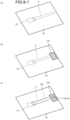
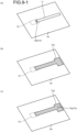
- FIG. 8-1 and FIG. 8-2 illustrate attachment of an electrode 10, wiring 11, insulating materials 12a and 12b, a front material 13a, and a back material 13b over time.
- the electrode 10 and the wiring 11 are first attached to a back surface 2b as illustrated in FIG. 8-1(a) and FIG.
- the insulating material 12a is attached to an outer surface 2a as illustrated in FIG. 8-1(b) and the front material 13a and 13b is attached to a clothing main body part 2 as illustrated in FIG. 8-2(b) .
- the insulating material 12b is attached to the back surface 2b as illustrated in FIG. 8-1(c) and FIG. 8-2(c) .
- the back materials 13b of the metal connectors 13-1 and 13-2 are inevitably fixed to the skin side surface 2b side.
- FIG. 8-1 and FIG. 8-2 direct contact of the back material 13b with the wiring 11 arranged on the skin side surface 2b side of the same surface allows a metal connector 13 to be attached in a state where the back material 13b is in contact with the wiring 11 and further both of the wiring 11 and the bottom of the back material 13b to be covered with the insulating material 12b.
- FIG. 9-1 and FIG. 9-2 are views illustrating an example of the arrangement structure of the wiring (outer surface placement) and the metal connector on the outer surface side and the skin side surface side not according to the present invention.
- FIG. 10 is an enlarged view of the arrangement structure of the wiring and the connector in FIG. 9-1.
- FIG. 9-1 and FIG. 9-2 illustrate the attachment of the electrode 10, the wiring 11, and the insulating materials 12a and 12b over time.
- the electrode 10 is firstly attached to the back surface 2b and the wiring 11 to the outer surface 2a to connect the electrode 10 and the wiring 11 to metal connectors 14a and 14b.
- the insulating material 12a is attached to the outer surface 2a and, at the same time, the front material 13a and 13b is attached to the clothing main body part 2. Thereafter, the insulating material 12b is attached to the back surface 2b as illustrated in FIG. 9-1(c) and FIG. 9-2 (c) .
- the wiring 11 and the front material 13a of the metal connector 13 are arranged on the same outer surface 2a, the wiring 11 is required to be covered with the insulating material 12a and the metal connector 13 is required to have a hole part 12c in the insulating material 12a and the front material 13a is required to be exposed through the hole part 12c so that the metal connector 13 functions as a connector.
- the hole part 12c of the insulating material 12a is enlarged to improve conductivity, the wiring 11 in the vicinity of the metal connector 13 is exposed. Therefore, as illustrated in FIG.
- the present invention is made in view of the above problems, and an object of the present invention is to provide a clothing for biological signal measurement that is comfortable in wear feeling and has excellent conductivity and insulation properties by arranging wirings arranged on the outer surface side of the clothing main body part to the skin side surface side through a cutout part provided in the clothing main body part.
- the present invention provides a clothing for biological signal measurement.
- the clothing includes: a clothing main body part; an electrode used by closely attaching on a skin side surface side of the clothing main body part; a wiring arranged on an outer surface side of the clothing main body part and electrically connected to the electrode by one end of the wiring; a metal connector including a front material and a back material, electrically connecting the other end of the wiring by fitting the front material and the back material, and connecting an electronic device to the front material; and an insulating material sealing the wiring and the back material of the metal connector.
- the wiring is arranged from the outer surface side to the skin side surface side through a cutout part provided in the clothing main body part and connected by direct contact with the back material of the metal connector penetrating the clothing main body part from a front side to a back side of the clothing main body part, and the insulating material is configured to seal the cutout part.
- a fabric part covering the wiring arranged on a surface of an outer side of the clothing main body part is sewn to a body of the clothing main body part. This makes the wiring and the insulating material invisible from a front side of the clothing when the clothing is put on, thus providing the clothing for biological signal measurement with excellent design properties.
- a front body of the clothing main body part is formed of a right front body and a left front body, and the right front body and the left front body are capable of being opened and closed, the electrode, the wiring, and the metal connector are provided on each of the right front body and the left front body, and the electronic device is connected to the metal connector of each of the right front body and the left front body by stepping over an opening and closing part of the right front body and the left front body.
- the clothing for biological signal measurement further includes an adapter having a first connector and a second connector, the first connector being on a front surface side of the adapter and connecting the electronic device, the second connector being on a back surface side of the adapter and connecting to the metal connector.
- the clothing for biological signal measurement in which the adapter includes an adapter main body constituted of a textile and formed by folding the textile in two, the first connector and the second connector are arranged on one surface of the textile, a wiring connecting the first connector and the second connector is arranged on an opposite side surface of the textile, and the wiring is sealed with an insulating material, and the adapter main body is folded in two so that each of the first connector and the second connector is exposed on both surfaces of the adapter main body.
- the wirings can be arranged on the outer surface side of the clothing main body part so that the wirings do not touch to skin and can achieve conduction with the metal connector. Therefore, the clothing for biological signal measurement is excellent in design properties and functionality.
- the clothing for biological signal measurement having a front-opening structure according to the present invention is very easy to be put on and taken off and easy to attach an electronic device. Consequently, discomfort feeling when the wearer puts on and takes off the clothing can be reduced and damage to the wiring caused by forcing the wearer's body passing through the clothing when the clothing is put on and taken off can be prevented.
- FIG. 1 is a schematic view illustrating one example of the clothing for biological signal measurement according to the first embodiment of the present invention.
- FIG. 2-1 is a partial view illustrating a wiring structure on the outer surface side of the clothing for biological signal measurement according to the first embodiment of the present invention
- FIG. 2-2 is a partial view illustrating a wiring structure on the skin side surface side of the clothing for biological signal measurement according to the first embodiment of the present invention
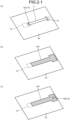
- FIG. 2-1 and FIG. 2-2 illustrate the attachment of an electrode 10, a wiring 11, and insulating materials 12a and 12b over time.
- the electrodes 10 are placed on the skin side surface under the chest in the vicinity of the sides of a clothing main body part 2, and one ends of the wirings 11 are connected to the electrodes 10.
- the wirings 11 are arranged on an outer surface 2a of the clothing main body part 2 and is electrically connected with the electrodes 10 arranged on the skin side surface side and connectors 14 (14a and 12b) having a structure formed of the front material and the back material similar to metal connectors 13 described below.
- the wirings 11 are entirely covered with the insulating materials 12a and 12b.
- natural fiber materials such as cotton and wool and synthetic fiber materials such as polyester and nylon used in ordinary clothing products can be used as the material for the clothing main body part 2 without any limitation.
- the material of the electrodes 10 is not particularly limited and commercially available medical Ag/AgCl electrodes with electrolyte paste, carbon filler mixed resins, Ag fabrics, conductive polymer-impregnated fabrics, and fabrics into which electrolytes are permeated can be used without limitation.
- the electrodes 10 are preferably formed by using the conductive polymer-impregnated fabric, whereby irritation to skin to which the electrodes 10 are closely attached can be reduced and durability can be improved.
- the electrodes 10 can be placed on a skin side surface 2b side of the clothing main body part 2 at two positions where a heart is sandwiched. Measuring potential difference from the heart allows the heart potential and the heart rate to be measured. As other measurements, the electrodes 10 are placed at positions corresponding to the muscles of the human body such as upper arm muscles, abdominal muscles, and quadriceps muscles, whereby muscle potential can be acquired.
- a method for sewing the electrodes 10 to the clothing main body part 2 a method for bonding the electrodes 10 using a thermocompression bonding material, or a method for directly printing a conductive material serving as the electrodes 10 on the clothing main body part 2 may be exemplified and these methods can be arbitrarily used.
- snaps can be placed at the positions where the electrodes 10 is fixed on the clothing main body part 2 to fasten the removable electrodes 10.
- known wiring materials can be used without limitation. It is important that the material is flexible and durable to washing because the wirings 11 are arranged on the clothing main body part 2.
- the wirings 11 are also required to be covered with the insulating materials 12a and 12b so as not to acquire signals from the human body and the like other than the site where the electrodes 10 are placed.
- a structure in which the insulating material is further sandwiched between the clothing main body part 2 and the wirings 11 is preferably formed in order that the wirings 11 are also insulated from the arranged clothing main body part 2.
- the metal connectors 13 each connected to the other ends of the wirings 11 extending from the electrodes 10 are arranged.
- An electronic device 20 is attached to the metal connectors 13 and the potential difference information from the heart measured by the electrodes 10 can be acquired through the wirings 11 and the metal connectors 13.
- the electronic device 20 can be attached to and detached from the front materials 13a of the metal connectors 13 using connectors 21.
- the metal connectors 13 are not particularly limited as long as the metal connectors are formed of metal and achieves electric conductivity between the front side and the back side by interlocking the front material 13a and the back material 13b from both surfaces of the clothing main body part 2 and partially penetrating.
- Use of metal connectors 13-1 and 13-2 having a structure illustrated in FIG. 7 allows passing properties at the sewing process to be excellent and handling to be easily performed.
- the wirings 11 are not arranged on the skin side surface 2b of the clothing main body part 2 but arranged on the outer surface 2a side, which is an opposite surface to the skin side surface 2b, and thus steamy feeling or abrasion of skin caused by direct contact of the wirings 11 and the insulating material 12a covering the wirings 11 with skin is not felt.
- a cutout part 2c is provided in the clothing main body part 2 in order to achieve both directions of the arrangement of the wiring 11 and the arrangement of the front materials 13a of the metal connectors 13 to which the electronic device 20 is attached are not on the skin side surface 2b side but on the outer surface 2a side of the clothing main body part 2.
- the wiring 11 is exposed on the skin side surface 2b side opposite to the outer surface 2a side (refer to FIG. 2-1(a) and FIG. 2-2(a) ).
- the wiring 11 and the cutout part 2c arranged on the outer surface 2a side of the clothing main body part 2 are covered with the insulating material 12a (refer to FIG. 2-1 (b) ).
- the back material 13b of the metal connector 13 is in direct contact with the wiring 11 exposed on the skin side surface 2b side to fit the front material 13a and back material 13b together so as to sandwich the clothing main body part 2 and the wiring 11, whereby the wiring 11 is conducted with the metal connector 13 (refer to FIG. 2-1(c) and FIG. 2-2(b) ).
- the wiring 11 exposed on the skin side surface 2b side is covered by the insulating material 12b together with the cutout part 2c in the clothing main body part 2 and the back material 13b of the metal connector 13 (refer to FIG. 2-2 (c) ).
- the electronic device 20 is connected to the front material 13a of the metal connector 13 exposed above the insulating material 12a. Forming the structure as described above allows both sufficient conduction of the wiring 11 and the metal connector 13 and sufficient insulation of the wiring to be satisfied.
- the cutout part 2c in the clothing main body part 2 for exposing the wiring 11 to the skin side surface 2b side may be a hole-shaped part into which the wiring 11 is inserted as illustrated in FIG. 2-1(a) and FIG. 2-2(a) .
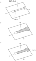
- the cutout part 2c may be replaced by a hollow structure 2d as illustrated in FIG. 3-1(a) and FIG. 3-2(a) .
- the wiring 11 and the cutout 2c or the hollow structure 2d in the clothing main body part 2 are covered with the insulating material 12a arranged on the outer surface 2a side and the insulating material 12b arranged on the skin side surface 2b side and, after achieving conduction with the wiring 11, the back material 13b of the metal connector 13 on the skin side surface 2b side is also covered with the insulating material 12b from above the conducted wiring 11, whereby the front material 13a on the outer surface 2a alone is exposed.
- arrangement of the wiring 11 on the skin side surface 2b side as illustrated in FIG. 8-2 causes the area where the insulating material 12b directly touches the skin to be large because the insulating material 12b covering the wiring 11 is arranged on the skin side surface 2b side. Consequently, steamy felling and friction feeling become larger.
- the wiring 11 is arranged on the outer surface 2a side of the clothing main body part 2 so that the wiring 11 does not touch the skin, the front material 13a of the metal connector 13 is in direct contact with the wiring 11 to achieve connection as illustrated in FIG. 9-1.
- Fixing the front material 13a of the metal connector 13 from above the front material 13a after applying the insulating material 12a to completely cover the wiring 11 with the insulating material 12a results in not securing conduction with the wiring 11. Even when a small hole part 12c is provided in the insulating material 12a, production efficiency deteriorates because contact between the metal connector 13 and the wiring 11 is likely to be insufficient when the wiring 11 and the metal connector 13 are slightly misaligned and time and effort are required for preparation.
- the wiring 11 in the vicinity of the front material 13a is inevitably exposed due to insufficient insulation, which causes noise and also deteriorates design properties.
- the wiring 11 is mainly provided on the outer surface 2a side of the clothing main body part 2 and thus steamy feeling and abrasion of skin caused by direct contact of the insulating material 12b with the skin can be reduced.
- the wiring 11 is in direct contact with the back material 13b of the metal connector 13 to achieve conduction with the metal connector 13 and the wiring 11 can be completely covered with the insulating materials 12a and 12b and thus high conductivity and insulation properties can be retained.
- FIG. 4 is a schematic view illustrating one examples of the clothing for biological signal measurement according to the second embodiment of the present invention.
- a fabric part 3 is sewn to the clothing main body part 2 so as to cover the wirings 11 arranged on the outer surface 2a side of the clothing main body part 2 in the clothing for biological signal measurement 1 according to the first embodiment.
- the wirings 11 are hidden in the fabric part 3 and thus the design properties of appearance do not deteriorate.
- the metal connectors 13 for connecting the electronic device 20 are arranged further above this fabric part 3 and thus the installation and removal of the electronic device 20 are not interrupted.
- the wirings 11 are placed on the outer surface of the clothing main body part 2 and one ends of the wirings 11 are electrically connected by the connectors to the electrode 10 arranged on the skin side surface side.
- the other ends of the wirings 11 are exposed on the skin side surface side by a cutout or a hollow structure not illustrated in FIG. 4 and bringing direct contact with the back material of the metal connectors 13 to achieve conduction between the wirings 11 and the metal connectors 13.
- the cutout or the hollow structure and the back material of the metal connectors 13 are covered with the insulating material.
- this fabric part 3 provides the effect of obtaining the clothing for biological signal measurement 1A having excellent signal acquisition performance and wearing feeling because when not only the wirings 11 but also the upper part of the electrodes 10 placed on the skin side surface 2b are covered, the double-layered part where the clothing main body part 2 and the fabric part 3 are overlapped generate the effect of pressing the electrodes 10 to the skin to prevent the electrodes 10 from slipping even when the clothing main body part 2 has loose stretch.
- the fabric part 3 may be formed of the same or different material as or from the clothing main body part 2.
- the entire circumference of the clothing main body part 2 is doubled in the necessary part alone, whereby the stretch power of the clothing for biological signal measurement 1A by which the electrodes 10 are pressed to the skin to be fixed is further improved, and thus the signal acquisition performance is excellent.
- the wirings 11 are arranged on the outer surface side and thus an area where the insulating material is in direct contact with the skin is small. Therefore, the steamy feeling and abrasion of skin caused by the insulating material can be reduced and both sufficient conduction between the wirings 11 and the metal connectors 13 and sufficient insulation of the wirings can be satisfied.
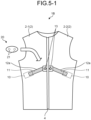
- FIG. 5-1 is a schematic view illustrating the clothing for biological signal measurement according to the third embodiment of the present invention.
- the front body of the clothing main body part 2 is formed of a right front body 2-1 and a left front body 2-2.
- a fastener 4 that can be opened and closed is attached between the right front body 2-1 and the left front body 2-2.
- the electrode 10, the wiring 11, and the metal connector 13 are provided on each of the right front body 2-1 and left front body 2-2.
- the wirings 11 are placed on the outer surface of the clothing main body part 2 and one ends of the wirings 11 are electrically connected by the connectors to the electrodes 10 that are arranged on the skin side surface side.
- the other ends of the wirings 11 are exposed on the skin side surface side by the cutout or the hollow structure not illustrated in FIG. 5-1 and bringing direct contact with the back material of the metal connectors 13 to achieve conduction between the wirings 11 and the metal connectors 13.
- the cutout or the hollow structure and the back material of the metal connectors 13 are covered with the insulating material.
- the electronic device 20 can be connected to the metal connectors 13 on the right front body 2-1 and left front body 2-2 in the form of stepping over the fastener 4.
- the clothing for biological signal measurement 1B is very easy to be put on and taken off even when the clothing main body part 2 is served as a compression wear formed by using a fabric with high stretch properties in order to ensure close attachment properties of the electrodes 10 to the skin.
- the clothing for biological signal measurement 1B also has the advantages of being easy to be taken off even when the fabric sticks to the skin due to perspiration and being easy to be put on even when stretch in the chest area is tight because a head or shoulders are not required to pass through when the clothing for biological signal measurement 1B is put on.
- the wirings 11 are arranged on the outer surface side and thus an area where the insulating material is in direct contact with the skin is small. Therefore, the steamy feeling and abrasion of skin caused by the insulating material can be reduced and both sufficient conduction between the wirings 11 and the metal connectors 13 and sufficient insulation of the wirings can be satisfied.
- Clothing for biological signal measurement 1C illustrated in FIG. 5-2 is clothing having the same configuration as the clothing for biological signal measurement 1B and allowing the front body to be fully opened except that the fabric part 3 is sewn in such a way that the wirings 11 are hidden. In addition to having the same effect as the clothing for biological signal measurement 1B, the clothing for biological signal measurement 1C has excellent design properties and signal acquisition performance.
- FIG. 6 is a schematic view illustrating the clothing for biological signal measurement and the electronic device according to the fourth embodiment of the present invention.
- FIG. 6 illustrates a state where an adapter 30 is attached to the clothing for biological signal measurement 1C in FIG. 5-1 .
- the adapter 30 includes first connectors 32 and second connectors 33, the first connectors 32 being on a front surface of an adapter body 31 and connecting a connector 21D of an electronic device 20D, the second connectors 33 being on a back surface side of the adapter body 31 and connecting to the front material 13a of the metal connectors 13.
- a distance between the metal connectors 13 may be more than a certain distance due to the attachment of the fasteners and a distance between the connectors of the electronic device desired to be used is narrow. Consequently, the electronic device may not be directly attached in some cases. In addition, cases where other electronic devices having different connector alignment are desired to be attached. Attaching the adapter 30 that uses the first connectors 31 corresponding to the connectors of the electronic device desired to be used to the clothing for biological signal measurement 1C allows the electronic device that cannot be directly connected to the metal connectors 13 to be attached.
- the adapter 30 may be a base in which the first connectors 32, the second connectors 33, and the wirings (not illustrated) on an adapter main body 31 formed of a plastic or rubber sheet or may be a product using textiles such as woven or knitted fabrics or non-woven fabrics.
- an adapter in which the adapter main body 31 is constituted of the textile and is folded in two is preferable.
- the present invention can be applied to the technology of acquiring bioelectrical signals by wearing a clothing equipped with the electronic device.
Landscapes
- Health & Medical Sciences (AREA)
- Life Sciences & Earth Sciences (AREA)
- General Health & Medical Sciences (AREA)
- Engineering & Computer Science (AREA)
- Molecular Biology (AREA)
- Medical Informatics (AREA)
- Veterinary Medicine (AREA)
- Biophysics (AREA)
- Pathology (AREA)
- Biomedical Technology (AREA)
- Heart & Thoracic Surgery (AREA)
- Physics & Mathematics (AREA)
- Public Health (AREA)
- Surgery (AREA)
- Animal Behavior & Ethology (AREA)
- Physical Education & Sports Medicine (AREA)
- Textile Engineering (AREA)
- Measurement And Recording Of Electrical Phenomena And Electrical Characteristics Of The Living Body (AREA)
Abstract
Description
- The present invention relates to a clothing for biological signal measurement including electrodes, wirings, and connectors, and used for a wearable device acquiring signals obtained from a living body using an electronic device worn on a human body.
- In recent years, the importance of daily health management has been pointed out. As one of the methods for health management, effectiveness in the early detection of a symptom of poor physical condition or heart disease that leads to trouble by recording and analyzing bioelectrical signals such as electrocardiograms over a long period of time has been known in preventive medicine. In order to acquire such bioelectrical signals over a long period of time, clothing to which sensors and an electronic device are attached has attracted attention (refer to Non-Patent Literature 1).
- In the clothing to which the sensors are attached, the electronic device for processing and recording the electrical signals or transmitting the electrical signals to outward is require to be fixed or connected. In addition, the clothing is further required to include wirings for electrical conduction between the electronic device and electrodes and connectors for connecting the wirings to the electronic device.
- As technology for the wiring and the connector, an example of connecting an electronic device serving as a heart rate sensor by attaching a conductive resin sheet including conductive particles as the electrodes and the wirings to the skin side surface of a shirt serving as a sensor, and attaching a metal hook to the wiring end and the front side of the shirt so as to conduct electricity has been described (Patent Literature 1). An example of attaching fiber electrodes impregnated with a conductive resin and conductive bodies serving as the wirings by connecting to the electrodes at the end on the skin side surface side of the clothing, covering the wirings with a waterproof insulating material, and connecting the other end of the wiring to a connection connector to conduct with the electronic device has been also described (Patent Literature 2).
- In either case, the wiring portion that transmits biological signals is required to be covered with the waterproof insulating material because contact with skin or other objects introduces noise into the biological signals.
- Non Patent Literature 1: David M.D. Ribeiro, et al, "A Real time, Wearable ECG and Continous Blood Pressure Monitoring System for First Responders", 33rd Annual International Conference of the IEEE EMBS, pp. 6894-6898, 2011
-
- Patent Literature 1:
WO 2018/221375 - Patent Literature 2:
Japanese Patent Application Laid-open No. 2017-42387 - However, the clothing for biological signal measurement provided with the waterproof-coated wiring on the skin side surface side has problems of uncomfortable wearing feeling, for example, accumulation of sweat causes heat rush to be formed because the insulating material does not absorb water and uncomfortable feeling is sensed by touching the insulating material to skin. On the other hand, in the case where waterproof-coated wirings are provided on the outer surface side, the following problems arise.
- The members used as connectors to the sensors, the electrodes, the wirings, and the electronic device are required to be fixed to a fabric serving as the base material of the clothing and thus are formed of a front material used for connecting to the external part, that is, a product called a snap or a hook made of a metal generally used as a clothing material or a similar product and a back material placed on the surface opposite to the front material sandwiching a base material such as a fabric. As the members, metal materials that a part of the back side member penetrates the fabric to deform inside of the front material by external force, whereby both of the members sandwich the fabric to fix are frequently used.
- In this case, bringing the wiring into direct contact with the metal connector over a large area is important in order to achieve sufficient electric conductivity of the wiring to the metal connector. On the other hand, the wiring is required to be insulated from skin and a wet cloth and thus the wirings are essentially covered with a waterproof insulating material. In addition, the wirings must be in contact with the metal connectors in a state where no insulating material exists between the wirings and the contact part of the metal connectors.
-
FIG. 7 is a schematic view related to an example of a metal connector structure and wiring arrangement.FIG. 8-1 and FIG. 8-2 are views illustrating an example of an arrangement structure of the wiring (skin side surface arrangement) and the metal connector on an outer surface side and a skin side surface side not according to the present invention.FIG. 7 illustrates a post-type metal connector 13-1 and a prong-type metal connector 13-2 as examples.FIG. 8-1 andFIG. 8-2 illustrate attachment of anelectrode 10,wiring 11,insulating materials front material 13a, and aback material 13b over time. In the case where the metal connector is placed on the skin side surface, theelectrode 10 and thewiring 11 are first attached to aback surface 2b as illustrated inFIG. 8-1(a) andFIG. 8-2(a) . Subsequently, theinsulating material 12a is attached to anouter surface 2a as illustrated inFIG. 8-1(b) and thefront material main body part 2 as illustrated inFIG. 8-2(b) . Thereafter, theinsulating material 12b is attached to theback surface 2b as illustrated inFIG. 8-1(c) andFIG. 8-2(c) . - As illustrated in
FIG. 7 , in the case where thefront materials 13a of the metal connectors 13-1 and 13-2 are attached toward theouter surface 2a of the clothingmain body part 2 in order to attach the electronic device, theback materials 13b of the metal connectors 13-1 and 13-2 are inevitably fixed to theskin side surface 2b side. As illustrated inFIG. 8-1 andFIG. 8-2 , direct contact of theback material 13b with thewiring 11 arranged on theskin side surface 2b side of the same surface allows ametal connector 13 to be attached in a state where theback material 13b is in contact with thewiring 11 and further both of thewiring 11 and the bottom of theback material 13b to be covered with theinsulating material 12b. -
FIG. 9-1 andFIG. 9-2 are views illustrating an example of the arrangement structure of the wiring (outer surface placement) and the metal connector on the outer surface side and the skin side surface side not according to the present invention.FIG. 10 is an enlarged view of the arrangement structure of the wiring and the connector inFIG. 9-1. FIG. 9-1 andFIG. 9-2 illustrate the attachment of theelectrode 10, thewiring 11, and theinsulating materials FIG. 9-1(a) andFIG. 9-2(a) , theelectrode 10 is firstly attached to theback surface 2b and thewiring 11 to theouter surface 2a to connect theelectrode 10 and thewiring 11 tometal connectors FIG. 9-1(b) andFIG. 9-2(b) , theinsulating material 12a is attached to theouter surface 2a and, at the same time, thefront material main body part 2. Thereafter, theinsulating material 12b is attached to theback surface 2b as illustrated inFIG. 9-1(c) andFIG. 9-2 (c) . - Even when the
wiring 11 and thefront material 13a of themetal connector 13 are arranged on the sameouter surface 2a, thewiring 11 is required to be covered with theinsulating material 12a and themetal connector 13 is required to have ahole part 12c in theinsulating material 12a and thefront material 13a is required to be exposed through thehole part 12c so that themetal connector 13 functions as a connector. As illustrated inFIG. 10(b) , however, when thehole part 12c of theinsulating material 12a is enlarged to improve conductivity, thewiring 11 in the vicinity of themetal connector 13 is exposed. Therefore, as illustrated inFIG. 10(c) , when theinsulating material 12a is attached and thereafter thefront material 13a of themetal connector 13 is fixed thereon in order to secure insulation properties, the conduction cannot be secured. In the case where asmall hole part 12c is formed in theinsulating material 12a to such a degree that thehole part 12c is hidden under thefront material 13a of themetal connector 13, poor connection due to insufficient contact between themetal connector 13 and thewiring 11 may occur. - The present invention is made in view of the above problems, and an object of the present invention is to provide a clothing for biological signal measurement that is comfortable in wear feeling and has excellent conductivity and insulation properties by arranging wirings arranged on the outer surface side of the clothing main body part to the skin side surface side through a cutout part provided in the clothing main body part.
- The present invention provides a clothing for biological signal measurement. The clothing includes: a clothing main body part; an electrode used by closely attaching on a skin side surface side of the clothing main body part; a wiring arranged on an outer surface side of the clothing main body part and electrically connected to the electrode by one end of the wiring; a metal connector including a front material and a back material, electrically connecting the other end of the wiring by fitting the front material and the back material, and connecting an electronic device to the front material; and an insulating material sealing the wiring and the back material of the metal connector. The wiring is arranged from the outer surface side to the skin side surface side through a cutout part provided in the clothing main body part and connected by direct contact with the back material of the metal connector penetrating the clothing main body part from a front side to a back side of the clothing main body part, and the insulating material is configured to seal the cutout part.
- A fabric part covering the wiring arranged on a surface of an outer side of the clothing main body part is sewn to a body of the clothing main body part. This makes the wiring and the insulating material invisible from a front side of the clothing when the clothing is put on, thus providing the clothing for biological signal measurement with excellent design properties.
- Further, provided is the clothing for biological signal measurement in which a front body of the clothing main body part is formed of a right front body and a left front body, and the right front body and the left front body are capable of being opened and closed, the electrode, the wiring, and the metal connector are provided on each of the right front body and the left front body, and the electronic device is connected to the metal connector of each of the right front body and the left front body by stepping over an opening and closing part of the right front body and the left front body.
- Moreover, the clothing for biological signal measurement further includes an adapter having a first connector and a second connector, the first connector being on a front surface side of the adapter and connecting the electronic device, the second connector being on a back surface side of the adapter and connecting to the metal connector. This provides the clothing for biological signal measurement, which allows the electronic device to be easily attached to the front of the body.
- Furthermore, provided is the clothing for biological signal measurement in which the adapter includes an adapter main body constituted of a textile and formed by folding the textile in two, the first connector and the second connector are arranged on one surface of the textile, a wiring connecting the first connector and the second connector is arranged on an opposite side surface of the textile, and the wiring is sealed with an insulating material, and the adapter main body is folded in two so that each of the first connector and the second connector is exposed on both surfaces of the adapter main body. Advantageous Effects of Invention
- According to the clothing for biological signal measurement according to the present invention, the wirings can be arranged on the outer surface side of the clothing main body part so that the wirings do not touch to skin and can achieve conduction with the metal connector. Therefore, the clothing for biological signal measurement is excellent in design properties and functionality.
- In addition, the clothing for biological signal measurement having a front-opening structure according to the present invention is very easy to be put on and taken off and easy to attach an electronic device. Consequently, discomfort feeling when the wearer puts on and takes off the clothing can be reduced and damage to the wiring caused by forcing the wearer's body passing through the clothing when the clothing is put on and taken off can be prevented.
-
-
FIG. 1 is a schematic view illustrating clothing for biological signal measurement and an electronic device according to the first embodiment of the present invention. -
FIG. 2-1 is a partial view illustrating a wring structure on the outer surface side of the clothing for biological signal measurement according to the first embodiment of the present invention. -
FIG. 2-2 is a partial view illustrating a wiring structure on the skin side surface side of the clothing for biological signal measurement according to the first embodiment of the present invention. -
FIG. 3-1 is a partial view illustrating a wiring structure on the outer surface side of the clothing for biological signal measurement according to a modified example of the first embodiment of the present invention. -
FIG. 3-2 is a partial view illustrating a wiring structure on the skin side surface side of the clothing for biological signal measurement according to a modified example of the first embodiment of the present invention. -
FIG. 4 is a schematic view illustrating clothing for biological signal measurement and an electronic device according to the second embodiment of the present invention. -
FIG. 5-1 is a schematic view illustrating clothing for biological signal measurement and an electronic device according to the third embodiment of the present invention. -
FIG. 5-2 is a schematic view illustrating clothing for biological signal measurement and an electronic device according to a modified example of the third embodiment of the present invention. -
FIG. 6 is a schematic view illustrating clothing for biological signal measurement and an electronic device according to the fourth embodiment of the present invention. -
FIG. 7 is a schematic view illustrating the structures of metal snaps used for metal connectors. -
FIG. 8-1 is a view illustrating an example of an arrangement structure of a wiring (skin side surface placement) and a metal connector not according to the present invention on an outer surface side. -
FIG. 8-2 is a view illustrating an example of the arrangement structure of the wiring (skin side surface placement) and the metal connector not according to the present invention on a skin side surface side. -
FIG. 9-1 is a view illustrating an example of the arrangement structure of the wiring (outer surface placement) and the metal connector not according to the present invention on the outer surface side. -
FIG. 9-2 is a view illustrating an example of the arrangement structure of the wiring (outer surface placement) and the metal connector not according to the present invention on the skin side surface side. -
FIG. 10 is an enlarged view of the arrangement structure of the wiring and the connector in FIG. 9-1. Description of Embodiments - Hereinafter, the suitable embodiments according to the present invention will be described with reference to the drawings. The present invention, however, is not limited to such embodiments.
-
FIG. 1 is a schematic view illustrating one example of the clothing for biological signal measurement according to the first embodiment of the present invention. FIG. 2-1 is a partial view illustrating a wiring structure on the outer surface side of the clothing for biological signal measurement according to the first embodiment of the present invention and FIG. 2-2 is a partial view illustrating a wiring structure on the skin side surface side of the clothing for biological signal measurement according to the first embodiment of the present invention FIG. 2-1 and FIG. 2-2 illustrate the attachment of anelectrode 10, awiring 11, and insulatingmaterials biological signal measurement 1, theelectrodes 10 are placed on the skin side surface under the chest in the vicinity of the sides of a clothingmain body part 2, and one ends of thewirings 11 are connected to theelectrodes 10. Thewirings 11 are arranged on anouter surface 2a of the clothingmain body part 2 and is electrically connected with theelectrodes 10 arranged on the skin side surface side and connectors 14 (14a and 12b) having a structure formed of the front material and the back material similar tometal connectors 13 described below. Thewirings 11 are entirely covered with the insulatingmaterials - In the present invention, natural fiber materials such as cotton and wool and synthetic fiber materials such as polyester and nylon used in ordinary clothing products can be used as the material for the clothing
main body part 2 without any limitation. - The material of the
electrodes 10 is not particularly limited and commercially available medical Ag/AgCl electrodes with electrolyte paste, carbon filler mixed resins, Ag fabrics, conductive polymer-impregnated fabrics, and fabrics into which electrolytes are permeated can be used without limitation. Theelectrodes 10 are preferably formed by using the conductive polymer-impregnated fabric, whereby irritation to skin to which theelectrodes 10 are closely attached can be reduced and durability can be improved. - The
electrodes 10 can be placed on askin side surface 2b side of the clothingmain body part 2 at two positions where a heart is sandwiched. Measuring potential difference from the heart allows the heart potential and the heart rate to be measured. As other measurements, theelectrodes 10 are placed at positions corresponding to the muscles of the human body such as upper arm muscles, abdominal muscles, and quadriceps muscles, whereby muscle potential can be acquired. - As methods for fixing the
electrodes 10 to the clothingmain body part 2, a method for sewing theelectrodes 10 to the clothingmain body part 2, a method for bonding theelectrodes 10 using a thermocompression bonding material, or a method for directly printing a conductive material serving as theelectrodes 10 on the clothingmain body part 2 may be exemplified and these methods can be arbitrarily used. Alternatively, snaps can be placed at the positions where theelectrodes 10 is fixed on the clothingmain body part 2 to fasten theremovable electrodes 10. - As the
wirings 11, known wiring materials can be used without limitation. It is important that the material is flexible and durable to washing because thewirings 11 are arranged on the clothingmain body part 2. Thewirings 11 are also required to be covered with the insulatingmaterials electrodes 10 are placed. In addition, a structure in which the insulating material is further sandwiched between the clothingmain body part 2 and thewirings 11 is preferably formed in order that thewirings 11 are also insulated from the arranged clothingmain body part 2. - At the center of the chest of the clothing
main body part 2, themetal connectors 13 each connected to the other ends of thewirings 11 extending from theelectrodes 10 are arranged. Anelectronic device 20 is attached to themetal connectors 13 and the potential difference information from the heart measured by theelectrodes 10 can be acquired through thewirings 11 and themetal connectors 13. Theelectronic device 20 can be attached to and detached from thefront materials 13a of themetal connectors 13 usingconnectors 21. - The
metal connectors 13 are not particularly limited as long as the metal connectors are formed of metal and achieves electric conductivity between the front side and the back side by interlocking thefront material 13a and theback material 13b from both surfaces of the clothingmain body part 2 and partially penetrating. Use of metal connectors 13-1 and 13-2 having a structure illustrated inFIG. 7 allows passing properties at the sewing process to be excellent and handling to be easily performed. - In the clothing for
biological signal measurement 1 illustrated inFIG. 1 , thewirings 11 are not arranged on theskin side surface 2b of the clothingmain body part 2 but arranged on theouter surface 2a side, which is an opposite surface to theskin side surface 2b, and thus steamy feeling or abrasion of skin caused by direct contact of thewirings 11 and the insulatingmaterial 12a covering thewirings 11 with skin is not felt. - In the present invention, a
cutout part 2c is provided in the clothingmain body part 2 in order to achieve both directions of the arrangement of thewiring 11 and the arrangement of thefront materials 13a of themetal connectors 13 to which theelectronic device 20 is attached are not on theskin side surface 2b side but on theouter surface 2a side of the clothingmain body part 2. Through thiscutout part 2c, thewiring 11 is exposed on theskin side surface 2b side opposite to theouter surface 2a side (refer toFIG. 2-1(a) andFIG. 2-2(a) ). Thewiring 11 and thecutout part 2c arranged on theouter surface 2a side of the clothingmain body part 2 are covered with the insulatingmaterial 12a (refer toFIG. 2-1 (b) ). Theback material 13b of themetal connector 13 is in direct contact with thewiring 11 exposed on theskin side surface 2b side to fit thefront material 13a and back material 13b together so as to sandwich the clothingmain body part 2 and thewiring 11, whereby thewiring 11 is conducted with the metal connector 13 (refer toFIG. 2-1(c) and FIG. 2-2(b) ). Thewiring 11 exposed on theskin side surface 2b side is covered by the insulatingmaterial 12b together with thecutout part 2c in the clothingmain body part 2 and theback material 13b of the metal connector 13 (refer toFIG. 2-2 (c) ). Theelectronic device 20 is connected to thefront material 13a of themetal connector 13 exposed above the insulatingmaterial 12a. Forming the structure as described above allows both sufficient conduction of thewiring 11 and themetal connector 13 and sufficient insulation of the wiring to be satisfied. - The
cutout part 2c in the clothingmain body part 2 for exposing thewiring 11 to theskin side surface 2b side may be a hole-shaped part into which thewiring 11 is inserted as illustrated inFIG. 2-1(a) andFIG. 2-2(a) . Alternatively, thecutout part 2c may be replaced by ahollow structure 2d as illustrated inFIG. 3-1(a) andFIG. 3-2(a) . In any case, together with preventing fraying and improving strength, it is important that thewiring 11 and thecutout 2c or thehollow structure 2d in the clothingmain body part 2 are covered with the insulatingmaterial 12a arranged on theouter surface 2a side and the insulatingmaterial 12b arranged on theskin side surface 2b side and, after achieving conduction with thewiring 11, theback material 13b of themetal connector 13 on theskin side surface 2b side is also covered with the insulatingmaterial 12b from above the conductedwiring 11, whereby thefront material 13a on theouter surface 2a alone is exposed. - On the other hand, as the clothing for biological signal measurement not according to the present invention, arrangement of the
wiring 11 on theskin side surface 2b side as illustrated in FIG. 8-2 causes the area where the insulatingmaterial 12b directly touches the skin to be large because the insulatingmaterial 12b covering thewiring 11 is arranged on theskin side surface 2b side. Consequently, steamy felling and friction feeling become larger. On the other hand, when thewiring 11 is arranged on theouter surface 2a side of the clothingmain body part 2 so that thewiring 11 does not touch the skin, thefront material 13a of themetal connector 13 is in direct contact with thewiring 11 to achieve connection as illustrated in FIG. 9-1. Fixing thefront material 13a of themetal connector 13 from above thefront material 13a after applying the insulatingmaterial 12a to completely cover thewiring 11 with the insulatingmaterial 12a results in not securing conduction with thewiring 11. Even when asmall hole part 12c is provided in the insulatingmaterial 12a, production efficiency deteriorates because contact between themetal connector 13 and thewiring 11 is likely to be insufficient when thewiring 11 and themetal connector 13 are slightly misaligned and time and effort are required for preparation. - Alternatively, when the
hole part 12c in the insulatingmaterial 12a is enlarged in order to improve conductivity, thewiring 11 in the vicinity of thefront material 13a is inevitably exposed due to insufficient insulation, which causes noise and also deteriorates design properties. In the clothing forbiological signal measurement 1 according to the first embodiment, thewiring 11 is mainly provided on theouter surface 2a side of the clothingmain body part 2 and thus steamy feeling and abrasion of skin caused by direct contact of the insulatingmaterial 12b with the skin can be reduced. Thewiring 11 is in direct contact with theback material 13b of themetal connector 13 to achieve conduction with themetal connector 13 and thewiring 11 can be completely covered with the insulatingmaterials -
FIG. 4 is a schematic view illustrating one examples of the clothing for biological signal measurement according to the second embodiment of the present invention. In clothing forbiological signal measurement 1A according to the second embodiment, afabric part 3 is sewn to the clothingmain body part 2 so as to cover thewirings 11 arranged on theouter surface 2a side of the clothingmain body part 2 in the clothing forbiological signal measurement 1 according to the first embodiment. In this case, thewirings 11 are hidden in thefabric part 3 and thus the design properties of appearance do not deteriorate. Themetal connectors 13 for connecting theelectronic device 20 are arranged further above thisfabric part 3 and thus the installation and removal of theelectronic device 20 are not interrupted. Similar to the clothing forbiological signal measurement 1 according to the first embodiment, in the clothing forbiological signal measurement 1A, thewirings 11 are placed on the outer surface of the clothingmain body part 2 and one ends of thewirings 11 are electrically connected by the connectors to theelectrode 10 arranged on the skin side surface side. The other ends of thewirings 11 are exposed on the skin side surface side by a cutout or a hollow structure not illustrated inFIG. 4 and bringing direct contact with the back material of themetal connectors 13 to achieve conduction between thewirings 11 and themetal connectors 13. The cutout or the hollow structure and the back material of themetal connectors 13 are covered with the insulating material. - In addition, this
fabric part 3 provides the effect of obtaining the clothing forbiological signal measurement 1A having excellent signal acquisition performance and wearing feeling because when not only thewirings 11 but also the upper part of theelectrodes 10 placed on theskin side surface 2b are covered, the double-layered part where the clothingmain body part 2 and thefabric part 3 are overlapped generate the effect of pressing theelectrodes 10 to the skin to prevent theelectrodes 10 from slipping even when the clothingmain body part 2 has loose stretch. Thefabric part 3 may be formed of the same or different material as or from the clothingmain body part 2. When the clothingmain body part 2 is covered with a belt-like fabric part 3 to the back surface to form a double-layer structure, the entire circumference of the clothingmain body part 2 is doubled in the necessary part alone, whereby the stretch power of the clothing forbiological signal measurement 1A by which theelectrodes 10 are pressed to the skin to be fixed is further improved, and thus the signal acquisition performance is excellent. Similar to the first embodiment, thewirings 11 are arranged on the outer surface side and thus an area where the insulating material is in direct contact with the skin is small. Therefore, the steamy feeling and abrasion of skin caused by the insulating material can be reduced and both sufficient conduction between thewirings 11 and themetal connectors 13 and sufficient insulation of the wirings can be satisfied. -
FIG. 5-1 is a schematic view illustrating the clothing for biological signal measurement according to the third embodiment of the present invention. In clothing forbiological signal measurement 1B, the front body of the clothingmain body part 2 is formed of a right front body 2-1 and a left front body 2-2. Afastener 4 that can be opened and closed is attached between the right front body 2-1 and the left front body 2-2. Theelectrode 10, thewiring 11, and themetal connector 13 are provided on each of the right front body 2-1 and left front body 2-2. In the clothing forbiological signal measurement 1B, similar to the clothing forbiological signal measurement 1 according to the first embodiment, thewirings 11 are placed on the outer surface of the clothingmain body part 2 and one ends of thewirings 11 are electrically connected by the connectors to theelectrodes 10 that are arranged on the skin side surface side. The other ends of thewirings 11 are exposed on the skin side surface side by the cutout or the hollow structure not illustrated inFIG. 5-1 and bringing direct contact with the back material of themetal connectors 13 to achieve conduction between thewirings 11 and themetal connectors 13. The cutout or the hollow structure and the back material of themetal connectors 13 are covered with the insulating material. - The
electronic device 20 can be connected to themetal connectors 13 on the right front body 2-1 and left front body 2-2 in the form of stepping over thefastener 4. The clothing forbiological signal measurement 1B is very easy to be put on and taken off even when the clothingmain body part 2 is served as a compression wear formed by using a fabric with high stretch properties in order to ensure close attachment properties of theelectrodes 10 to the skin. The clothing forbiological signal measurement 1B also has the advantages of being easy to be taken off even when the fabric sticks to the skin due to perspiration and being easy to be put on even when stretch in the chest area is tight because a head or shoulders are not required to pass through when the clothing forbiological signal measurement 1B is put on. In addition, similar to the first embodiment, thewirings 11 are arranged on the outer surface side and thus an area where the insulating material is in direct contact with the skin is small. Therefore, the steamy feeling and abrasion of skin caused by the insulating material can be reduced and both sufficient conduction between thewirings 11 and themetal connectors 13 and sufficient insulation of the wirings can be satisfied. Clothing forbiological signal measurement 1C illustrated inFIG. 5-2 is clothing having the same configuration as the clothing forbiological signal measurement 1B and allowing the front body to be fully opened except that thefabric part 3 is sewn in such a way that thewirings 11 are hidden. In addition to having the same effect as the clothing forbiological signal measurement 1B, the clothing forbiological signal measurement 1C has excellent design properties and signal acquisition performance. -
FIG. 6 is a schematic view illustrating the clothing for biological signal measurement and the electronic device according to the fourth embodiment of the present invention.FIG. 6 illustrates a state where anadapter 30 is attached to the clothing forbiological signal measurement 1C inFIG. 5-1 . - The
adapter 30 includesfirst connectors 32 andsecond connectors 33, thefirst connectors 32 being on a front surface of anadapter body 31 and connecting aconnector 21D of anelectronic device 20D, thesecond connectors 33 being on a back surface side of theadapter body 31 and connecting to thefront material 13a of themetal connectors 13. - In the clothing for
biological signal measurement metal connectors 13 may be more than a certain distance due to the attachment of the fasteners and a distance between the connectors of the electronic device desired to be used is narrow. Consequently, the electronic device may not be directly attached in some cases. In addition, cases where other electronic devices having different connector alignment are desired to be attached. Attaching theadapter 30 that uses thefirst connectors 31 corresponding to the connectors of the electronic device desired to be used to the clothing forbiological signal measurement 1C allows the electronic device that cannot be directly connected to themetal connectors 13 to be attached. - The
adapter 30 may be a base in which thefirst connectors 32, thesecond connectors 33, and the wirings (not illustrated) on an adaptermain body 31 formed of a plastic or rubber sheet or may be a product using textiles such as woven or knitted fabrics or non-woven fabrics. In particular, an adapter in which the adaptermain body 31 is constituted of the textile and is folded in two is preferable. A textile adapter having a shape in which thefirst connectors 32 and thesecond connectors 33 are arranged on the one surface of the textile, the wirings are arranged on the opposite surface, the textile is folded after the wirings are sealed with the insulating material, and thefirst connectors 32 and thesecond connectors 33 are exposed on the respective twofold surfaces is suitable for directly attaching to the clothing close to a human body because the wirings are not exposed and the touch to the human body is soft. - The present invention can be applied to the technology of acquiring bioelectrical signals by wearing a clothing equipped with the electronic device.
-
- 1
- Clothing for biological signal measurement
- 2
- Clothing main body part
- 2a
- Outer surface
- 2b
- Skin side surface
- 2c
- Cutout part
- 2d
- Hollow structure
- 2-1
- Right front body
- 2-2
- Left front body
- 3
- Fabric part
- 4
- Fastener
- 10
- Electrode
- 11
- Wiring
- 12a, 12b
- Insulating material
- 13
- Metal connector
- 14
- Connector
- 20, 20D
- Electronic device
- 21, 21D
- Connector
- 30
- Adapter
- 31
- Adapter main body
- 32
- First connector
- 33
- Second connector
Claims (5)
- A clothing for biological signal measurement, the clothing comprising:a clothing main body part;an electrode used by closely attaching on a skin side surface side of the clothing main body part;a wiring arranged on an outer surface side of the clothing main body part and electrically connected to the electrode by one end of the wiring;a metal connector including a front material and a back material, electrically connecting the other end of the wiring by fitting the front material and the back material, and connecting an electronic device to the front material; andan insulating material sealing the wiring and the back material of the metal connector, whereinthe wiring is arranged from the outer surface side to the skin side surface side through a cutout part provided in the clothing main body part and connected by direct contact with the back material of the metal connector penetrating the clothing main body part from a front side to a back side of the clothing main body part, andthe insulating material is configured to seal the cutout part.
- The clothing for biological signal measurement according to claim 1, wherein a fabric part covering the wiring arranged on a surface of an outer side of the clothing main body part is sewn to a body of the clothing main body part.
- The clothing for biological signal measurement according to claim 1 or 2, whereina front body of the clothing main body part is formed of a right front body and a left front body, and the right front body and the left front body are capable of being opened and closed,the electrode, the wiring, and the metal connector are provided on each of the right front body and the left front body, andthe electronic device is connected to the metal connector of each of the right front body and the left front body by stepping over an opening and closing part of the right front body and the left front body.
- The clothing for biological signal measurement according to claim 3, further comprising an adapter having a first connector and a second connector, the first connector being on a front surface side of the adapter and connecting the electronic device, the second connector being on a back surface side of the adapter and connecting to the metal connector.
- The clothing for biological signal measurement according to claim 4, whereinthe adapter includes an adapter main body constituted of a textile and formed by folding the textile in two,the first connector and the second connector are arranged on one surface of the textile, a wiring connecting the first connector and the second connector is arranged on an opposite side surface of the textile, and the wiring is sealed with an insulating material, andthe adapter main body is folded in two so that each of the first connector and the second connector is exposed on both surfaces of the adapter main body.
Applications Claiming Priority (2)
| Application Number | Priority Date | Filing Date | Title |
|---|---|---|---|
| JP2020172793 | 2020-10-13 | ||
| PCT/JP2021/037915 WO2022080417A1 (en) | 2020-10-13 | 2021-10-13 | Garment for biological signal measurement |
Publications (2)
| Publication Number | Publication Date |
|---|---|
| EP4230137A1 true EP4230137A1 (en) | 2023-08-23 |
| EP4230137A4 EP4230137A4 (en) | 2025-01-08 |
Family
ID=81209186
Family Applications (1)
| Application Number | Title | Priority Date | Filing Date |
|---|---|---|---|
| EP21880154.6A Withdrawn EP4230137A4 (en) | 2020-10-13 | 2021-10-13 | CLOTHING FOR MEASURING BIOLOGICAL SIGNALS |
Country Status (5)
| Country | Link |
|---|---|
| US (1) | US12465258B2 (en) |
| EP (1) | EP4230137A4 (en) |
| JP (1) | JP7722191B2 (en) |
| CN (1) | CN116261426B (en) |
| WO (1) | WO2022080417A1 (en) |
Families Citing this family (1)
| Publication number | Priority date | Publication date | Assignee | Title |
|---|---|---|---|---|
| EP4516224A4 (en) * | 2022-04-26 | 2025-09-10 | Mitsufuji Corp | BELTS AND CLOTHING |
Family Cites Families (19)
| Publication number | Priority date | Publication date | Assignee | Title |
|---|---|---|---|---|
| US3498291A (en) * | 1966-02-10 | 1970-03-03 | Lockheed Aircraft Corp | Body signal sensing electrode apparatus |
| US8886281B2 (en) | 2006-06-08 | 2014-11-11 | Suunto Oy | Snap and electrode assembly for a heart rate monitor belt |
| KR100895300B1 (en) * | 2007-07-20 | 2009-05-07 | 한국전자통신연구원 | Biosignal garments and biosignal processing systems |
| US8776264B2 (en) * | 2009-04-03 | 2014-07-15 | Ware Llc | Garments for providing access for sensors to contact skin |
| WO2011131234A1 (en) * | 2010-04-20 | 2011-10-27 | Wearable Information Technologies, S.L. (Weartech) | Sensor apparatus adapted to be incorporated in a garment |
| US8443634B2 (en) * | 2010-04-27 | 2013-05-21 | Textronics, Inc. | Textile-based electrodes incorporating graduated patterns |
| JP2016106877A (en) * | 2014-12-08 | 2016-06-20 | 日本電信電話株式会社 | Bioelectrode and clothing |
| WO2016201118A1 (en) * | 2015-06-09 | 2016-12-15 | Bardy Diagnostics, Inc. | Wearable electrocardiography and physiology monitoring ensemble |
| JP6457355B2 (en) | 2015-08-27 | 2019-01-23 | 日本電信電話株式会社 | Wearable electrode and biological signal monitoring system |
| TW201740828A (en) * | 2016-05-30 | 2017-12-01 | 金鼎聯合科技纖維股份有限公司 | Method of sewing a wire |
| US10925540B2 (en) * | 2016-08-18 | 2021-02-23 | MAD Apparel, Inc. | Garment with conductive thread exposed on both sides |
| JP2018143383A (en) * | 2017-03-02 | 2018-09-20 | 学校法人四恩学園 | Clothing-type wearable sensor |
| US11641899B2 (en) | 2017-05-29 | 2023-05-09 | Toyobo Co., Ltd. | Garment for measuring biological information |
| JP2019068901A (en) * | 2017-10-06 | 2019-05-09 | グンゼ株式会社 | Bioelectrode and garment having the same |
| JP7017067B2 (en) * | 2017-11-17 | 2022-02-08 | 東洋紡株式会社 | Clothes for measuring biometric information |
| JP2019126509A (en) * | 2018-01-24 | 2019-08-01 | 日本電信電話株式会社 | Wearable device |
| CN108742593A (en) * | 2018-06-22 | 2018-11-06 | 广东脉搏医疗科技有限公司 | Cardioelectric monitor wearable device and cardioelectric monitor system |
| CN113226178A (en) * | 2018-10-12 | 2021-08-06 | 东丽株式会社 | Biological signal monitoring clothes |
| CN209932728U (en) * | 2019-03-21 | 2020-01-14 | 成都柔电云科科技有限公司 | Portable electrocardio monitoring clothing |
-
2021
- 2021-10-13 EP EP21880154.6A patent/EP4230137A4/en not_active Withdrawn
- 2021-10-13 US US18/027,966 patent/US12465258B2/en active Active
- 2021-10-13 JP JP2021564735A patent/JP7722191B2/en active Active
- 2021-10-13 WO PCT/JP2021/037915 patent/WO2022080417A1/en not_active Ceased
- 2021-10-13 CN CN202180067340.4A patent/CN116261426B/en active Active
Also Published As
| Publication number | Publication date |
|---|---|
| WO2022080417A1 (en) | 2022-04-21 |
| JP7722191B2 (en) | 2025-08-13 |
| EP4230137A4 (en) | 2025-01-08 |
| CN116261426B (en) | 2025-08-05 |
| US20230363681A1 (en) | 2023-11-16 |
| JPWO2022080417A1 (en) | 2022-04-21 |
| CN116261426A (en) | 2023-06-13 |
| US12465258B2 (en) | 2025-11-11 |
Similar Documents
| Publication | Publication Date | Title |
|---|---|---|
| EP2143376B1 (en) | A sensor arrangeable on the skin | |
| JP7013604B2 (en) | Bioelectrodes and clothing | |
| KR100863064B1 (en) | Clothing for measuring bio-signals and its manufacturing method | |
| JP6073776B2 (en) | Bioelectric signal monitor clothing | |
| US11185118B2 (en) | Sensor connection assembly for integration with garment | |
| KR20190040975A (en) | Biomedical Signal Detection Medical | |
| TWI879900B (en) | Wearables for biosignal monitoring | |
| JPH02142534A (en) | Biological signal sampling and transmitting device | |
| JP2016106877A (en) | Bioelectrode and clothing | |
| CN105726012A (en) | Induction garment and making method thereof and human body index collecting system capable of performing collecting through induction garment | |
| US12465258B2 (en) | Clothing for biological signal measurement | |
| US12070316B2 (en) | Wearable electrode | |
| JP6514129B2 (en) | Wearable electrode | |
| EP4400044A1 (en) | Wearable article including an encapsulated elongation sensor | |
| CN211022654U (en) | Electrocardio-belt | |
| HK1058298B (en) | A sensor arrangeable on the skin |
Legal Events
| Date | Code | Title | Description |
|---|---|---|---|
| STAA | Information on the status of an ep patent application or granted ep patent |
Free format text: STATUS: THE INTERNATIONAL PUBLICATION HAS BEEN MADE |
|
| PUAI | Public reference made under article 153(3) epc to a published international application that has entered the european phase |
Free format text: ORIGINAL CODE: 0009012 |
|
| STAA | Information on the status of an ep patent application or granted ep patent |
Free format text: STATUS: REQUEST FOR EXAMINATION WAS MADE |
|
| 17P | Request for examination filed |
Effective date: 20230316 |
|
| AK | Designated contracting states |
Kind code of ref document: A1 Designated state(s): AL AT BE BG CH CY CZ DE DK EE ES FI FR GB GR HR HU IE IS IT LI LT LU LV MC MK MT NL NO PL PT RO RS SE SI SK SM TR |
|
| DAV | Request for validation of the european patent (deleted) | ||
| DAX | Request for extension of the european patent (deleted) | ||
| A4 | Supplementary search report drawn up and despatched |
Effective date: 20241205 |
|
| RIC1 | Information provided on ipc code assigned before grant |
Ipc: A61B 5/256 20210101AFI20241129BHEP |
|
| GRAP | Despatch of communication of intention to grant a patent |
Free format text: ORIGINAL CODE: EPIDOSNIGR1 |
|
| STAA | Information on the status of an ep patent application or granted ep patent |
Free format text: STATUS: GRANT OF PATENT IS INTENDED |
|
| INTG | Intention to grant announced |
Effective date: 20250718 |
|
| STAA | Information on the status of an ep patent application or granted ep patent |
Free format text: STATUS: THE APPLICATION HAS BEEN WITHDRAWN |
|
| 18W | Application withdrawn |
Effective date: 20250925 |