EP4228726B1 - Resuscitator - Google Patents
Resuscitator Download PDFInfo
- Publication number
- EP4228726B1 EP4228726B1 EP21786483.4A EP21786483A EP4228726B1 EP 4228726 B1 EP4228726 B1 EP 4228726B1 EP 21786483 A EP21786483 A EP 21786483A EP 4228726 B1 EP4228726 B1 EP 4228726B1
- Authority
- EP
- European Patent Office
- Prior art keywords
- squeeze bag
- filter
- bag
- squeeze
- filter arrangement
- Prior art date
- Legal status (The legal status is an assumption and is not a legal conclusion. Google has not performed a legal analysis and makes no representation as to the accuracy of the status listed.)
- Active
Links
Images



Classifications
-
- A—HUMAN NECESSITIES
- A61—MEDICAL OR VETERINARY SCIENCE; HYGIENE
- A61M—DEVICES FOR INTRODUCING MEDIA INTO, OR ONTO, THE BODY; DEVICES FOR TRANSDUCING BODY MEDIA OR FOR TAKING MEDIA FROM THE BODY; DEVICES FOR PRODUCING OR ENDING SLEEP OR STUPOR
- A61M16/00—Devices for influencing the respiratory system of patients by gas treatment, e.g. ventilators; Tracheal tubes
- A61M16/0057—Pumps therefor
- A61M16/0084—Pumps therefor self-reinflatable by elasticity, e.g. resuscitation squeeze bags
-
- A—HUMAN NECESSITIES
- A61—MEDICAL OR VETERINARY SCIENCE; HYGIENE
- A61M—DEVICES FOR INTRODUCING MEDIA INTO, OR ONTO, THE BODY; DEVICES FOR TRANSDUCING BODY MEDIA OR FOR TAKING MEDIA FROM THE BODY; DEVICES FOR PRODUCING OR ENDING SLEEP OR STUPOR
- A61M16/00—Devices for influencing the respiratory system of patients by gas treatment, e.g. ventilators; Tracheal tubes
- A61M16/0057—Pumps therefor
- A61M16/0078—Breathing bags
-
- A—HUMAN NECESSITIES
- A61—MEDICAL OR VETERINARY SCIENCE; HYGIENE
- A61M—DEVICES FOR INTRODUCING MEDIA INTO, OR ONTO, THE BODY; DEVICES FOR TRANSDUCING BODY MEDIA OR FOR TAKING MEDIA FROM THE BODY; DEVICES FOR PRODUCING OR ENDING SLEEP OR STUPOR
- A61M16/00—Devices for influencing the respiratory system of patients by gas treatment, e.g. ventilators; Tracheal tubes
- A61M16/08—Bellows; Connecting tubes ; Water traps; Patient circuits
- A61M16/0816—Joints or connectors
-
- A—HUMAN NECESSITIES
- A61—MEDICAL OR VETERINARY SCIENCE; HYGIENE
- A61M—DEVICES FOR INTRODUCING MEDIA INTO, OR ONTO, THE BODY; DEVICES FOR TRANSDUCING BODY MEDIA OR FOR TAKING MEDIA FROM THE BODY; DEVICES FOR PRODUCING OR ENDING SLEEP OR STUPOR
- A61M16/00—Devices for influencing the respiratory system of patients by gas treatment, e.g. ventilators; Tracheal tubes
- A61M16/10—Preparation of respiratory gases or vapours
- A61M16/105—Filters
- A61M16/1055—Filters bacterial
-
- A—HUMAN NECESSITIES
- A61—MEDICAL OR VETERINARY SCIENCE; HYGIENE
- A61M—DEVICES FOR INTRODUCING MEDIA INTO, OR ONTO, THE BODY; DEVICES FOR TRANSDUCING BODY MEDIA OR FOR TAKING MEDIA FROM THE BODY; DEVICES FOR PRODUCING OR ENDING SLEEP OR STUPOR
- A61M16/00—Devices for influencing the respiratory system of patients by gas treatment, e.g. ventilators; Tracheal tubes
- A61M16/10—Preparation of respiratory gases or vapours
- A61M16/105—Filters
- A61M16/106—Filters in a path
- A61M16/107—Filters in a path in the inspiratory path
-
- A—HUMAN NECESSITIES
- A61—MEDICAL OR VETERINARY SCIENCE; HYGIENE
- A61M—DEVICES FOR INTRODUCING MEDIA INTO, OR ONTO, THE BODY; DEVICES FOR TRANSDUCING BODY MEDIA OR FOR TAKING MEDIA FROM THE BODY; DEVICES FOR PRODUCING OR ENDING SLEEP OR STUPOR
- A61M16/00—Devices for influencing the respiratory system of patients by gas treatment, e.g. ventilators; Tracheal tubes
- A61M16/20—Valves specially adapted to medical respiratory devices
- A61M16/208—Non-controlled one-way valves, e.g. exhalation, check, pop-off non-rebreathing valves
-
- A—HUMAN NECESSITIES
- A61—MEDICAL OR VETERINARY SCIENCE; HYGIENE
- A61M—DEVICES FOR INTRODUCING MEDIA INTO, OR ONTO, THE BODY; DEVICES FOR TRANSDUCING BODY MEDIA OR FOR TAKING MEDIA FROM THE BODY; DEVICES FOR PRODUCING OR ENDING SLEEP OR STUPOR
- A61M16/00—Devices for influencing the respiratory system of patients by gas treatment, e.g. ventilators; Tracheal tubes
- A61M16/08—Bellows; Connecting tubes ; Water traps; Patient circuits
- A61M16/0816—Joints or connectors
- A61M16/0841—Joints or connectors for sampling
- A61M16/0858—Pressure sampling ports
-
- A—HUMAN NECESSITIES
- A61—MEDICAL OR VETERINARY SCIENCE; HYGIENE
- A61M—DEVICES FOR INTRODUCING MEDIA INTO, OR ONTO, THE BODY; DEVICES FOR TRANSDUCING BODY MEDIA OR FOR TAKING MEDIA FROM THE BODY; DEVICES FOR PRODUCING OR ENDING SLEEP OR STUPOR
- A61M16/00—Devices for influencing the respiratory system of patients by gas treatment, e.g. ventilators; Tracheal tubes
- A61M16/10—Preparation of respiratory gases or vapours
- A61M16/105—Filters
- A61M16/106—Filters in a path
- A61M16/1065—Filters in a path in the expiratory path
-
- A—HUMAN NECESSITIES
- A61—MEDICAL OR VETERINARY SCIENCE; HYGIENE
- A61M—DEVICES FOR INTRODUCING MEDIA INTO, OR ONTO, THE BODY; DEVICES FOR TRANSDUCING BODY MEDIA OR FOR TAKING MEDIA FROM THE BODY; DEVICES FOR PRODUCING OR ENDING SLEEP OR STUPOR
- A61M2205/00—General characteristics of the apparatus
- A61M2205/75—General characteristics of the apparatus with filters
- A61M2205/7509—General characteristics of the apparatus with filters for virus
-
- A—HUMAN NECESSITIES
- A61—MEDICAL OR VETERINARY SCIENCE; HYGIENE
- A61M—DEVICES FOR INTRODUCING MEDIA INTO, OR ONTO, THE BODY; DEVICES FOR TRANSDUCING BODY MEDIA OR FOR TAKING MEDIA FROM THE BODY; DEVICES FOR PRODUCING OR ENDING SLEEP OR STUPOR
- A61M2205/00—General characteristics of the apparatus
- A61M2205/75—General characteristics of the apparatus with filters
- A61M2205/7518—General characteristics of the apparatus with filters bacterial
Definitions
- the present disclosure relates to a resuscitator including a self-inflating squeeze bag having a squeeze bag inlet opening and a squeeze bag outlet opening, the squeeze bag inlet opening accommodating a squeeze bag inlet valve housing including a squeeze bag inlet valve arrangement being adapted to allow inflow of air into the squeeze bag and being adapted to prevent outflow of air from the squeeze bag through the squeeze bag inlet opening, the squeeze bag outlet opening accommodating a patient valve housing including a patient valve arrangement being adapted to allow outflow of air from the squeeze bag into the patient valve housing and being adapted to prevent inflow of air into the squeeze bag through the squeeze bag outlet opening, the patient valve housing further including a patient connection port for ventilation of a patient and a patient expiration outlet port for outlet of exhaled gas from the patient valve housing to the surroundings, and wherein the resuscitator includes a filter arrangement located upstream the squeeze bag outlet opening in order to filter air before reaching the patient valve arrangement from the squeeze bag.
- US 5,163,424 discloses a disposable resuscitator comprising an elastically compressible elongated squeeze bag having a first opening, a one-way valve for the intake of oxygen-containing gas into the bag mounted in said first opening, a second opening which is in airtight communication with a valve housing in the form of a transparent pipe having a pipe stub for the attachment of the resuscitator to a facial mask, and an outlet for exhalation air.
- WO 2006/091829 A2 discloses a bag mask resuscitator including a flexible tubing having a proximal end and a distal end with the proximal end engaged to a resuscitation bag and the distal end adapted for engagement with a valve assembly.
- the valve assembly includes a coupling member adapted for quick engagement and disengagement of the flexible tubing from the valve assembly using a simple action.
- US 3,216,413 discloses a portable artificial respirator in the form of two bellows arranged one inside the other.
- the inner bellows form a volume for the intake of fresh air.
- the volume made up by the space between the inner bellows and the outer bellows is for the extraction of foul air.
- a drilled plate placed outside air intake valves may be provided with a breathing filter.
- the device has a T-tube that also acts as a handle so the operator can pump in an up down movement to alternately fill the inner volume with air by pulling the handle up and ventilate the air to the patient by pressing the handle down towards the patient's face.
- the device is not self-inflating and does not include an elastic squeeze bag.
- EP 0 818 217 A1 discloses a closed circuit breathing bag for a person that breathes spontaneously and is not a resuscitator that assists in ventilating a patient.
- the exhaled CO2 is converted to O2 in the filter in a carbon filter that contains potassium superoxide. This allows the person to re-breath his/her own exhalation air as it is enriched with O2 when passing the carbon filter. Therefore, this is a completely different technology compared to a resuscitator which is being used for ventilating persons that are not breathing spontaneously.
- CN 206979809 U , CN 201542910 U and US 2001/029950 A1 relate to resuscitator bags provided with an air filter at the air intake end.
- Resuscitator bags are used for manual ventilation of patients in emergency care (pre-hospital) or in hospital care, e.g. by anaesthetists in the initial phase of anaesthesia for surgical procedures.
- the aerosols contained in the surrounding air may contain particles and/or microbial or viral pathogens.
- the aerosols contained in the surrounding air may contain particles and/or microbial or viral pathogens.
- particles and/or pathogens may be transferred to the patient resulting in a risk that the patient catches diseases of bacterial or viral origin (e.g. Covid-19 or other airways related diseases) if the inspiratory air contains such particles and/or pathogens.
- the aerosols contained in the expiration air form the ventilated patient may contain microbial or viral pathogens that are spread to the environment surrounding the patient and thus also the operator and/or clinician (anaesthetist, nurse, pre-hospital emergency care etc.) providing the manual ventilation to the patient.
- pathogens may be transferred from the patient to the operator resulting in a risk that the operator catches diseases of bacterial or viral origin (e.g. Covid-19 or other airways related diseases) if the operator inhales aerosols expelled from the patient through the outlet on the PEEP valve on the resuscitator bag.
- a filter (catching aerosols including pathogen bacteria and/or virus present herein) is provided on the patient inspiratory port and thus between the face mask, laryngeal mask or ET tube and the resuscitator bag while performing manual ventilation of the patient.
- This filter does, however, increase the dead space of the ventilatory pathway leading to increased rebreathing of air, which may result in hypercapnia.
- the dead space is that volume of previously exhaled gas which is delivered to the patient in the succeeding inflation.
- placing the filter at the patient inspiratory port will lead to an increased inspiratory and expiratory resistance.
- US 2012/0012111 A1 discloses an application for a Positive End-Expiratory Pressure (PEEP) valve including a filter media in the air flow between a patient interface and exit vent(s).
- the patient interface is connected to a patient airway system and the exit vents exhaust exhalation gasses into the atmosphere.
- the filter prevents or reduces the passage of microbes from the patient's exhalation gasses into the atmosphere.
- the PEEP valve provides positive gas pressure to a patient's lungs, requiring a predetermined exhalation gas pressure to be exceeded before releasing exhalation gasses into the atmosphere.
- the filter media is arranged in a filter holder inserted between the patient airway system and the PEEP valve, thereby increasing the size of the entire resuscitator arrangement.
- US 3,548,822 A discloses a resuscitator including a self-inflating squeeze bag, an inlet valve arrangement and a patient valve housing.
- a filter may be arranged outside the inlet valve arrangement.
- US 5,222,491 A discloses a temporary patient ventilator which has guy wires attached to the inside resilient walls of the airbag which are pulled to collapse the airbag.
- a filter may be arranged outside the inlet valve.
- An object of the present disclosure is to provide a resuscitator provided with a filter arrangement for the inspiratory air of the patient without increasing the dead space of the ventilatory pathway and without any substantial increase of the inspiratory and/or expiratory resistance.
- the filter arrangement is located inside the squeeze bag.
- the dead space associated with the patient connection port and its connection with the patient airway device is not influenced by the filter arrangement.
- the expiratory resistance experienced by the patient is not influenced, and the inspiratory resistance may be influenced very little, depending on the size and location of the filter arrangement.
- the inflation resistance may be influenced very little or not at all, also depending on the size and location of the filter arrangement.
- the filter arrangement By locating the filter arrangement inside the squeeze bag, the overall dimensions of the resuscitator may be unaffected by the filter arrangement, and the resuscitator will be less bulky when the filter is arranged inside the squeeze bag. Furthermore, the filter area can be made larger when arranging the filter inside the squeeze bag. This allows for maximizing the filter area which may reduce inspiratory resistance.
- a peripheral edge of the filter arrangement fits a cross-section of a wall of the squeeze bag, and the peripheral edge of the filter arrangement is attached to the wall of the squeeze bag.
- the filter arrangement is attached at the squeeze bag outlet opening.
- the peripheral edge of the filter arrangement has been attached to the wall of the squeeze bag by assembling the squeeze bag from two complementary squeeze bag parts and sandwiching the peripheral edge of the filter arrangement between opposed edges of the complementary squeeze bag parts. Thereby, a strong connection between the peripheral edge of the filter arrangement and the wall of the squeeze bag may be obtained.
- the squeeze bag is elongated in a longitudinal direction extending from the squeeze bag inlet opening to the squeeze bag outlet opening, and the filter arrangement has a longitudinal direction being arranged obliquely to the longitudinal direction of the squeeze bag.
- the filter area of the filter arrangement may be maximized.
- the filter area of a single sheet filter may be maximized.
- the filter arrangement is attached at the squeeze bag inlet opening.
- the inflation resistance may be influenced very little or not at all, depending on how much or whether the filter arrangement itself is deformed when squeezing the squeeze bag. If the filter arrangement itself is not deformed when squeezing the squeeze bag, the inflation resistance may not at all be influenced by the filter arrangement.
- the filter arrangement is attached to the squeeze bag inlet valve housing.
- the filter arrangement has a peripheral edge attached along a corresponding edge of a filter opening of the squeeze bag inlet valve housing.
- the filter arrangement has the form of a flat filter.
- the filter arrangement includes one or more pocket filters and/or filter bags. Thereby, the effective filtration area may be increased.
- the filter arrangement has the form of a filter bag having a ring-formed peripheral part extending away from the squeeze bag inlet opening and being arranged adjacent an inside wall of the bag.
- the form of the filter bag having a ring-formed peripheral part extending away from the squeeze bag inlet opening may allow packing the resuscitator for transport by pressing opposed ends of the squeeze bag, corresponding to the ends provided with the squeeze bag inlet opening and the squeeze bag outlet opening, respectively, into the interior of the squeeze bag.
- the filter arrangement has the form of a pocket filter or filter bag being tapered in a direction extending away from the squeeze bag inlet opening.
- the filter arrangement has the form of a number of filter bags arranged in a ring-form adjacent an inside wall of the squeeze bag.
- the influence on the filter arrangement and consequently on the inflation resistance from squeezing the squeeze bag may be minimised, because the number of filter bags arranged in a ring-form may flex towards the inner of the squeeze bag when the squeeze bag is squeezed. Therefore, squeezing the squeeze bag will not result in much air being pressed through the filter bags.
- the number of filter bags arranged in a ring-form may allow packing the resuscitator for transport by pressing opposed ends of the squeeze bag, corresponding to the ends provided with the squeeze bag inlet opening and the squeeze bag outlet opening, respectively, into the interior of the squeeze bag.
- the one or more pocket filters and/or filter bags is/are adapted to be maintained in shape by means of a flexible skeleton. Thereby, it may be ensured that the one or more pocket filters and/or filter bags are maintained in their optimal shape for filtering when the squeeze bag flexes elastically back to its normal form after it has been squeezed.
- the filter arrangement includes a filter material having an effective filtration area which is greater than, preferably at least 25 times, more preferred at least 40 times, and even more preferred at least 50 times a minimum cross-sectional flow area of the patient connection port.
- the filter arrangement includes a filter material based on textiles.
- the filter material may generally form a bacterial and/or viral filter.
- the patient expiration outlet port is provided with a PEEP valve for the control of the flow and/or pressure at the patient expiration outlet port, and the PEEP valve has a PEEP valve filter.
- PEEP valve for the control of the flow and/or pressure at the patient expiration outlet port
- the PEEP valve has a PEEP valve filter. This may reduce and/or eliminate that the operator is exposed to pathogens (bacteria and/or virus) while manually ventilating a contagious patient using the resuscitator. Additionally, the risk of spreading of pathogens to the surroundings (e.g. in airborne aerosols) may be reduced and/or eliminated.
- the PEEP valve includes a PEEP valve housing having a peripheral PEEP valve housing wall, the peripheral PEEP valve housing wall is provided with a number of patient expiration outlet openings for outlet of exhaled gas from the PEEP valve housing to the surroundings, and the PEEP valve filter is arranged to filter air flowing through the patient expiration outlet openings.
- the peripheral PEEP valve housing wall is cylindrical.
- peripheral PEEP valve housing wall is tapering in a direction away from the squeeze bag.
- the PEEP valve filter is covering an outside of the peripheral PEEP valve housing wall.
- the PEEP valve filter is integrated in the PEEP valve.
- the PEEP valve filter is adapted to click on the PEEP valve.
- the present disclosure furthermore relates to a PEEP valve as described above for attachment to a patient expiration outlet port of a resuscitator of any suitable type.
- the PEEP valve is adapted for the control of the flow and/or pressure at the patient expiration outlet port, and the PEEP valve has a PEEP valve filter.
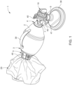
- Fig. 1 shows a well-known prior art resuscitator 1 including a self-inflating elastic squeeze bag 2, without filtration of the inspiratory air.
- the resuscitator 1 may in a manner well-known in the art be used for manual ventilation of patients in emergency care (pre-hospital) or in hospital care, e.g. by anaesthetists in connection with anaesthesia during surgical procedures.
- the self-inflating elastic squeeze bag 2 may for instance be made of styrene-ethylene-butylene-styrene block copolymer (SEBS) or poly vinyl chloride (PVC).
- SEBS styrene-ethylene-butylene-styrene block copolymer
- PVC poly vinyl chloride
- the squeeze bag 2 may be compressed by an operator from it relaxed state as illustrated in the figures to a compressed (not shown) state. Subsequently to being compressed by the operator, the compressed squeeze bag 2, when let free from its compression by the operator, will by means of its elasticity return to its relaxed state and thereby drag respiration air into the squeeze bag.
- the self-inflating squeeze bag 2 has a squeeze bag inlet opening 3 and a squeeze bag outlet opening 4.
- the squeeze bag inlet opening 3 accommodates a squeeze bag inlet valve housing 5 including a squeeze bag inlet valve arrangement 6 (not visible in Fig. 1 ) being adapted to allow inflow of air into the squeeze bag 2 and being adapted to prevent outflow of air from the squeeze bag 2 through the squeeze bag inlet opening 3.
- the squeeze bag outlet opening 4 accommodates a patient valve housing 7 including a patient valve arrangement 8 (not visible in Fig. 1 ) being adapted to allow outflow of air from the squeeze bag 2 into the patient valve housing 7 and being adapted to prevent inflow of air into the squeeze bag 2 through the squeeze bag outlet opening 4.
- the patient valve housing 7 further includes a patient connection port 9 for directing air to and from the patient airways and a patient expiration outlet port 10 for outlet of exhaled gas from the patient valve housing 7 to the surroundings.
- the patient connection port 9 is provided with a face mask 38 for ventilation of a patient, but, alternatively, among others, the patient connection port 9 could be provided with a laryngeal mask or an endotracheal tube (ET tube) for ventilation of a patient.
- ET tube endotracheal tube
- the patient valve housing 7 is provided with a manometer port 40 with cap, a so-called M-port 41 for installation of medication or measurement of CO 2 and a pressure limiting valve 42, and the patient expiration outlet port 10 is provided with splash guards 39 in order to prevent an operator from splashes of fluid.
- the patient expiration outlet port 10 may be provided with a PEEP valve 33 as illustrated in Figs. 19 to 22 in order to control the pressure in a patient's lungs at the end of expiration.
- the squeeze bag inlet valve housing 5 is further provided with an oxygen reservoir bag 29 and an oxygen inlet connector 43 (not visible in Fig. 1 ) adapted to fill the oxygen reservoir bag 29 with oxygen from an oxygen supply.
- the squeeze bag 2 is provided with a support strap 39.
- Figs. 2 to 9 and 23 to 25 illustrate different embodiments of a resuscitator 1 of the same type as illustrated in Fig. 1 , however, according to the present disclosure, provided with a filter arrangement 11 located upstream the squeeze bag outlet opening 4 in order to filter air before reaching the patient valve arrangement 8 from the squeeze bag 2.
- Figs. 10 to 18 illustrate different embodiments of a resuscitator 1 of a somewhat different type than that of Fig. 1 , however, according to the present disclosure, also provided with a filter arrangement 11 located upstream the squeeze bag outlet opening 4.
- the filter arrangement 11 is located inside the squeeze bag 2 (according to the principle of the invention), at the squeeze bag inlet opening 3 or outside the squeeze bag 2 (outside the invention).
- the filter arrangement 11 may also be located at the squeeze bag outlet opening 4, in arrangements corresponding to those illustrated at the squeeze bag inlet opening 3, and the filter arrangement 11 may further be located at the squeeze bag outlet opening 4 inside or outside the squeeze bag 2.
- Fig. 23 illustrates an embodiment in which the filter arrangement 11 is located inside the squeeze bag 2 at the squeeze bag outlet opening 4 in that the filter arrangement 11, in the form of a flat filter 18, is attached to the squeeze bag patient valve housing 7.
- the resuscitator 1 illustrated in Fig. 23 is of the same type as the resuscitator illustrated in Fig. 1 , however, the patient valve housing 7 has been adapted somewhat in order to provide for a larger diameter of the patient valve housing 7 at the connection to the squeeze bag outlet opening 4.
- the illustrated flat filter 18 may have a larger diameter. It is noted that the illustrated flat filter 18 in both the embodiment illustrated in Fig. 23 and the embodiment illustrated in Fig. 10 could be covered on one or both its sides by means of a respective possibly detachable grid, grille, perforated plate or other arrangement suitable to maintain the shape of the flat filter 18 and suitable to hold the flat filter 18 in place.
- the patient valve housing 7 may be connected detachably to the squeeze bag 2 so that the filter arrangement 11 may easily be replaced, if the need should arise, for instance because of a polluted filter.
- the filter arrangement 11 in all embodiments in which the filter arrangement 11 is located inside the squeeze bag 2, it could be advantageous if the patient valve housing 7 and/or the squeeze bag inlet valve housing 5 would be connected detachably to the squeeze bag 2 so that the filter arrangement 11 could easily be replaced.
- filter arrangements 11 having constructions as shown in any of the Figs. 2 , 8 , 10 , 12 to 15 or 24 to 25 and being attached to the inlet valve housing 5, could alternatively be arranged at the squeeze bag outlet opening 4 as an alternative to the flat filter shown in Fig. 23 .
- the inlet valve arrangement 6 and the patient valve arrangement 8 which are not visible in Fig. 1 are illustrated in the cross-sectional views of Figs. 2 to 9 and 23 to 25 .
- the inlet valve arrangement 6 is of a different type than that illustrated in Figs. 2 to 9 and 23 to 25
- the patient valve arrangement 8 is of the same type as that illustrated in Figs. 2 to 9 as well as 24 and 25.
- the oxygen inlet connector 43 is not visible in Fig. 1 , but may be seen in Figs. 10 , 11 , 12 , 14 and 16 .
- an oxygen inlet port 44 arranged in the squeeze bag inlet valve housing 5 and connected to the oxygen inlet connector 43 is visible in Figs.
- the squeeze bag inlet valve housing 5 is provided with an oxygen reservoir bag connector port 45 to which the oxygen reservoir bag 29 is connected.
- the oxygen reservoir bag 29 may be filled with oxygen directly from the oxygen inlet connector 43 without any intermediate valves.
- the inlet valve arrangement 6 is arranged in the squeeze bag inlet valve housing 5 as follows.
- the squeeze bag inlet valve housing 5 has a circular disc 46 which along its periphery is attached to the squeeze bag inlet opening 3.
- the central part of the circular disc 46 has the shape of a valve seat with holes 47 which are covered by a thin circular elastic valve flap 48 located on the interior side of the circular disc 46 and which is attached to the valve seat by a centrally located pin 49.
- the circular elastic valve flap 48 together with the valve seat forms a main inlet one-way valve 52 of the inlet valve arrangement 6.
- the exterior side of the disc 46 is integral with the squeeze bag inlet valve housing 5 having two parallel side walls 50 with holes 51, these side walls forming valve seats for an ambient air intake valve 53 mounted on the inside of the squeeze bag inlet valve housing 5 and a relief valve 54 mounted on the outside of the squeeze bag inlet valve housing 5, respectively.
- the ambient air intake valve 53 comprises in addition to the holes 51 a thin circular valve flap 55 which is attached to the valve seat by a pin 56.
- the relief valve 54 comprises another thin circular valve flap 57 which is attached to the valve seat by means of a pin 58.
- the squeeze bag inlet valve housing 5 is at the end opposite to the disc 46 provided with the oxygen reservoir bag connector port 45.
- the inlet valve arrangement 6 is arranged in the squeeze bag inlet valve housing 5 as follows.
- the squeeze bag inlet valve housing 5 has a main inlet one-way valve 52 corresponding largely to the main inlet one-way valve 52 of the embodiment of Figs. 2 to 9 and 23 to 25 , although of slightly different construction.
- the end 30 of squeeze bag inlet valve housing 5 facing away from the squeeze bag 2 is provided with an ambient air inlet valve 31 corresponding to the ambient air inlet valve 53 of the embodiment of Figs. 2 to 9 and 23 to 25.
- the end 30 of squeeze bag inlet valve housing 5 is also provided with a relief valve 54 corresponding to that of the embodiment of Figs. 2 to 9 and 23 to 25.
- the filter arrangements 11 illustrated in Figs. 2 , 8 , 9 , 12 , 14 and 23 to 25 may be applied to the squeeze bag inlet valve housing 5 and inlet valve arrangement 6 illustrated in Fig. 10 without any substantial modifications of the squeeze bag inlet valve housing 5 or the inlet valve arrangement 6.
- the filter arrangement 11 illustrated in Fig. 10 may be applied to the squeeze bag inlet valve housing 5 and inlet valve arrangement 6 illustrated in Figs. 2 , 8 , 9 , 12 , 14 and 23 to 25 without any substantial modifications of the squeeze bag inlet valve housing 5 or the inlet valve arrangement 6.
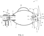
- the patient valve arrangement 8 includes a single elastic valve flap 59 closing against a squeeze bag outlet valve seat 60 of the patient valve housing 7 in its relaxed state when the squeeze bag 2 is not compressed by an operator. In this state, the single valve flap 59 allows the patient to exhale through the patient connection port 9 and the patient expiration outlet port 10, and further prevents inflow of air into the squeeze bag 2 through the squeeze bag outlet opening 4.
- the single elastic valve flap 59 abuts a patient expiration outlet valve seat 61, thereby preventing communication between the patient connection port 9 and the patient expiration outlet port 10, and the single valve flap 59 allows outflow of air from the squeeze bag 2 through the squeeze bag outlet opening 4, into the patient valve housing 7 and further into the patient connection port 9 in order to ventilate the patient.
- the single elastic valve flap 59 is held by a valve pin 62.
- the filter arrangement 11 is located inside the squeeze bag 2. This may have the advantage that the overall dimensions of the resuscitator 1 may be unaffected by the filter arrangement 11, and the resuscitator 1 will be less bulky when the filter arrangement 11 is located inside the squeeze bag 2. Furthermore, it may be an advantage that the effective filtration area may be maximised which may reduce inspiratory resistance.
- a peripheral edge 12 of the filter arrangement 11 fits a cross-section of a wall 13 of the squeeze bag 2, and the peripheral edge 12 of the filter arrangement 11 is attached to the wall 13 of the squeeze bag 2.
- the filter arrangement 11 may be a flat filter 18 or a flat arrangement of a corrugated filter that collapses and expands with the compression and re-expansion of the squeeze bag 2.
- the filter arrangement 11 may be attached to an inside wall 22 of the squeeze bag 2, e.g. by gluing, hot melt etc.
- the filter arrangement 11 could be provided with a flexible rim that is attached and held in position by friction or by being glued, e.g. between protrusions or shoulders, on the inside wall 22 of the squeeze bag 2.
- the peripheral edge 12 of the filter arrangement 11 has been attached to the wall 13 of the squeeze bag 2 by assembling the squeeze bag 2 from two complementary squeeze bag parts and sandwiching the peripheral edge 12 of the filter arrangement between opposed edges of the complementary squeeze bag parts. After arranging the filter arrangement 11 inside a first squeeze bag part, the two squeeze bag parts of the squeeze bag is assembled, e.g. by gluing and/or hot melt, etc. The filter arrangement 11 may thereby be attached to the inside of the squeeze bag 2 prior to or during assembly of the bag, e.g. by gluing and/or hot melt etc.
- the squeeze bag 2 is elongated in a longitudinal direction 14 extending from the squeeze bag inlet opening 3 to the squeeze bag outlet opening 4, and the filter arrangement 11 has a longitudinal direction 15 being arranged obliquely to the longitudinal direction 14 of the squeeze bag 2.
- the filter area of the filter arrangement 11 may be maximized.
- the filter area of a flat filter 18 in the form of a single sheet filter may be maximised.
- the filter arrangement 11 is attached at the squeeze bag inlet opening 3.
- the inflation resistance may be influenced very little or not at all, depending on how much or whether the filter arrangement 11 itself is deformed when squeezing the squeeze bag 2. If the filter arrangement 11 itself is not deformed when squeezing the squeeze bag 2, the inflation resistance may not at all be influenced by the filter arrangement 11. It is noted that when placing the filter arrangement 11 at the squeeze bag inlet opening 3, the compressed squeeze bag 2, when let free from its compression by an operator, will by means of its elasticity in practice drag respiration air in through the filter arrangement 11.
- the filter arrangement 11 takes up a relatively large part of the inner volume of the squeeze bag 2 and is therefore substantially deformed when squeezing the squeeze bag 2.
- the filter arrangement 11 takes up a relatively small part of the inner volume of the squeeze bag 2 and is arranged so that it is relatively little deformed when squeezing the squeeze bag 2. Therefore, when the squeeze bag of the embodiment of Fig. 24 is compressed, the inflation resistance may be influenced relatively more than it is the case when the squeeze bag of the embodiment of Fig. 25 is compressed.
- the filter arrangement 11 is advantageously attached to the squeeze bag inlet valve housing 5. More specifically, the filter arrangement 11 has a peripheral edge 12 attached along a corresponding edge 16 of a filter opening 17 of the squeeze bag inlet valve housing 5. However, alternatively, in these embodiments, the filter arrangement 11 could be attached directly to the inside wall 22 of the squeeze bag 2.
- the filter arrangement 11 has the form of a flat filter 18. According to these embodiments, the filter arrangement 11 does not need to be flexible, because compression of the squeeze bag 2 does not also compress the flat filter 18.
- the filter arrangement 11 may be attached by means of a compression ring 62 having a protrusion 63 mating with a corresponding cut-out 64 at the end of the squeeze bag inlet valve housing 5 arranged inside the squeeze bag 2.
- the filter arrangement 11 may be attached to the squeeze bag inlet valve housing 5 by means of gluing or by using hot melt.
- the filter arrangement 11 includes one or more pocket filters and/or filter bags 19.
- the filter arrangement 11 has the form of a filter bag 19 having a ring-formed peripheral part 20 extending away from the squeeze bag inlet opening 3 and being arranged adjacent an inside wall 21 of the squeeze bag 2.
- the form of the filter bag 19 having a ring-formed peripheral part 20 extending away from the squeeze bag inlet opening 3 may allow packing the resuscitator for transport by pressing opposed ends of the squeeze bag 2, corresponding to the ends provided with the squeeze bag inlet opening 3 and the squeeze bag outlet opening 4, respectively, into the interior of the squeeze bag 2.
- the filter arrangement 11 has the form of a pocket filter or filter bag 19 being tapered in a direction extending away from the squeeze bag inlet opening 3.
- the influence on the filter arrangement 11 and consequently on the inflation resistance from squeezing the squeeze bag 2 may be minimised, because the volume of air inside the pocket filter or filter bag 19 may be less at a central area of the squeeze bag 2 where the squeeze bag 2 is squeezed.
- the filter arrangement 11 has the form of a relatively large balloon-formed pocket filter or filter bag 19 taking up most of the internal volume of the squeeze bag 2 when the squeeze bag 2 is not compressed by an operator.
- the effective filtration area may be maximised.
- the internal wall of the squeeze bag 2 could be provided with a number of protrusions, such as dot-like knobs or bosses, providing for a certain space between the balloon-formed pocket filter or filter bag 19 and the internal wall of the squeeze bag 2 and thereby avoiding that the filter material contacts the internal wall.
- the balloon-formed pocket filter or filter bag 19 is prevented from being pressed close against the inlet of the patient valve arrangement 8. This could be done by adapting the size of the balloon-formed pocket filter or filter bag 19, in particular in its lengthwise direction, or by providing the circumference of the inlet of the patient valve arrangement 8 in the squeeze bag 2 with protrusions or indentations.
- the filter arrangement 11 has the form of a pocket filter or filter bag 19 being tapered in a direction extending away from the squeeze bag inlet opening 3.
- the pocket filter or filter bag 19 is provided with a circular peripheral edge 12 attached along a corresponding edge 16 of a filter opening 17 of the squeeze bag inlet valve housing 5.
- the filter arrangement 11 could be attached directly to the inside wall 22 of the squeeze bag 2.
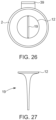
- the pocket filter or filter bag 19 is rather flat and slightly V-formed when seen from above in Fig. 25 , as illustrated in Fig. 27 .
- the pocket filter or filter bag 19 has a rectangular circumference.
- the pocket filter or filter bag 19 has a thin vertically arranged free end part.
- the squeeze bag 2 When the squeeze bag 2 is operated, it is held by the handle 39 and compressed symmetrically about the vertical cross-sectional plane. Thereby, the influence on the filter arrangement 11 and consequently on the inflation resistance from squeezing the squeeze bag 2 may be minimised, because the pocket filter or filter bag 19 is so thin in the compression direction of the squeeze bag 2 that the pocket filter or filter bag 19 is very little compressed.
- the filter arrangement 11 has the form of a number of filter bags 19 arranged in a ring-form 22 adjacent an inside wall 2 of the squeeze bag 2.
- the number of filter bags 19 arranged in the ring-form 22 may allow packing the resuscitator 1 for transport by pressing opposed ends of the squeeze bag, corresponding to the ends provided with the squeeze bag inlet opening 3 and the squeeze bag outlet opening 4, respectively, into the interior of the squeeze bag 2.
- the filter arrangement 11 may have the form of a number of tapering filter bags 19 arranged evenly or in any suitable distribution over the cross-sectional area of the squeeze bag 2. Advantages of the tapering filter bags 19 may be as described above.
- the one or more pocket filters and/or filter bags 19 is/are adapted to be maintained in shape by means of a flexible skeleton 23. Thereby, it may be ensured that the one or more pocket filters and/or filter bags 19 are maintained in their optimal shape for filtering when the squeeze bag 2 flexes elastically back to its normal form after it has been squeezed.
- a flexible skeleton 23 may likewise be employed in the pocket filters and/or filter bags 19 of the embodiments of Figs. 2 and 8 .
- the filter arrangement 11 is located outside the squeeze bag 2.
- the squeeze bag inlet valve housing 5 has a peripheral inlet valve housing wall 24 which extends beyond the squeeze bag inlet opening 3 and is provided with a number of ambient air inlet openings 25 for the intake of air from the surroundings into the squeeze bag inlet valve housing 5.
- the peripheral inlet valve housing wall 24 is cylindrical.
- the peripheral inlet valve housing wall 24 is tapering in a direction away from the squeeze bag 2.
- the filter arrangement 11 is arranged to filter air flowing through the ambient air inlet openings 25.
- the filter arrangement 11 has the form of a filter material 26 covering an inside of the peripheral inlet valve housing wall 24.
- the filter arrangement 11 has the form of a filter material 26 covering an outside of the peripheral inlet valve housing wall 24.
- filter material 26 could be protected by some sort of external cage or perforated wall, screen, grille, etc.
- the filter arrangement 11 has the form of a ring-formed filter bag 27 arranged on an outside of the peripheral inlet valve housing wall 24.
- the ring-formed filter bag 27 extends beyond the inlet valve housing 5 in a direction away from the squeeze bag 2. Furthermore, as seen, in this embodiment, a part 28 of the ring-formed filter bag 27 surrounds an oxygen reservoir bag 29 arranged at an end 30 of the squeeze bag inlet valve housing 5 opposed to the squeeze bag 2.
- the ring-formed filter bag 27 may be adapted to be maintained in shape by means of a not shown flexible skeleton. Thereby, similar advantages as those discussed above in connection with the embodiments of Figs. 12 to 14 may be achieved.
- the squeeze bag inlet valve housing 5 has an inlet valve housing end wall 30 facing away from the squeeze bag 2, and the inlet valve housing end wall 30 is provided with an ambient air inlet valve 31.
- the filter arrangement 11 has the form of a tubular filter 32 extending from the ambient air inlet valve 31.
- the tubular filter 32 extends in a direction away from the squeeze bag 2, which direction may be in a longitudinal direction of the squeeze bag 2, as seen in Fig. 16 , or in a transverse direction to the inlet valve housing 5, as illustrated in Figs. 17 and 18 . It is noted that in the embodiment as illustrated in Fig. 17 , the oxygen inlet connector 43 is hidden behind the tubular filter 32.
- the filter arrangement 11 includes a filter material having an effective filtration area which is greater than, preferably at least 25 times, more preferred at least 40 times, and even more preferred at least 50 times a minimum cross-sectional flow area of the patient connection port 9.
- An effective filtration area can be defined as the total area of the filter media that is exposed to the flow of liquid or air, that is usable for filtration. This may for instance be designated in square centimetres (cm 2 ).
- the filter arrangement 11 may include a filter material based on textiles.
- the filter arrangement 11 may generally include a bacterial and/or viral filter. Such a filter arrangement 11 may be able to remove up to 99,99% or 99,9999% of bacteria or virus from air.
- the filter arrangement 11 may typically include a single layer or usually multiple layers of non-woven textiles made from fibres of polyester, polypropylene, acrylics or polystyrene or mixtures thereof. Alternatively, two, three or more layers (e.g. of different arrangements) of the same fibre or fibre mixture may be used. Each layer may be of different fibres and/or different arrangements.
- the filter arrangement 11 may typically include at least one (such as two or three) layers of non-woven polypropylene fibres, or a triple layer filter with acrylic/polystyrene nonwoven fibres.
- the filter arrangement 11 preferably includes a non-woven polymer fibre layer with a scrim layer on each surface.
- the filters may be flat or shaped filters with a non-woven fibre layer (e.g. of spun polymer fibers, such as a blend of different synthetic polymer fibers, or one type of fibers, such as spun polypropylene (PP) fibers).
- the fibres may be treated to have an electrostatic, preferably positive, charged surface.
- the density of this non-woven filter layer is e.g. between 100 g/m2 and 400 g/m2 (Grams Per Square Meter).
- the density of the non-woven filter layer is preferably 150-350, more preferred 150-300 even more preferred 150-250 and most preferred 100-200 g/m2.
- the filter may be provided with scrim layers, such as thin (15g/m2) layers of hydrophobic textile membrane (of non-woven polymer, e.g. a polypropylene (PP)) on both surfaces of the non-woven layer.
- the electrostatic charge on the surface of the fibres attract aerosols or particles that may carry microbes or virus. Most airborne bacteria and virus use aerosols as a transport media. The aerosols are produced when people sneeze or cough. The surface charge of the aerosols results in that the aerosols are attracted to the electrostatically charged filter material, thus providing an improved filter efficiency.
- suitable commercially available electrostatic filters are e.g. TECHNOSTAT ® or TECHNOSTAT PLUS by Hollingsworth & Vose.
- the patient expiration outlet port 10 of a prior art resuscitator as illustrated in Fig. 1 or of a resuscitator according to the present disclosure as illustrated in any of the Figs. 2 to 18 may be provided with a PEEP valve 33 for the control of the flow and/or pressure at the patient expiration outlet port 10.
- Figs. 19 to 22 illustrates a PEEP valve 33 according to the present disclosure, which PEEP valve 33 may be fitted on any of the resuscitators as illustrated in Figs. 1 to 18 , or on any other suitable prior art resuscitator, wherein the PEEP valve 33 has a PEEP valve filter 34. This may reduce and/or eliminate that the operator is exposed to pathogens (bacteria and/or virus) while manually ventilating a contagious patient using the resuscitator.
- pathogens bacteria and/or virus
- the PEEP valve 33 includes a PEEP valve housing 35 having a peripheral PEEP valve housing wall 36, wherein the peripheral PEEP valve housing wall 36 is provided with a number of patient expiration outlet openings 37 for outlet of exhaled gas from the PEEP valve housing 35 to the surroundings, and wherein the PEEP valve filter 34 is arranged to filter air flowing through the patient expiration outlet openings 37.
- the PEEP valve 33 includes a rotatable handle 65 threaded onto the PEEP valve housing 35 in order to adjust the valve opening of a valve element 66 in relation to a valve seat 67.
- the rotatable handle 65 is acting on the valve element 66 by means of a compression spring 68 and the valve element 66 is guided by means of a spindle 69.
- a tubular element 70 may be arranged between the compression spring 68 and the valve element 66 as seen in Fig. 21 .
- peripheral PEEP valve housing wall 36 is cylindrical.
- peripheral PEEP valve housing wall 36 is tapering in a direction away from the squeeze bag 2.
- the PEEP valve filter 34 is covering an outside of the peripheral PEEP valve housing wall 36.
- the PEEP valve filter 34 may be integrated in the PEEP valve 33, or the PEEP valve filter 34 may be adapted to click on the PEEP valve 33.
- a PEEP valve is a spring loaded valve that a patient may exhale against.
- PEEP is an abbreviation for positive end-expiratory pressure according to a method of ventilation in which airway pressure is maintained above atmospheric pressure at the end of exhalation by means of a mechanical impedance, usually a valve.
Landscapes
- Health & Medical Sciences (AREA)
- Pulmonology (AREA)
- Emergency Medicine (AREA)
- Heart & Thoracic Surgery (AREA)
- Anesthesiology (AREA)
- Biomedical Technology (AREA)
- Engineering & Computer Science (AREA)
- Hematology (AREA)
- Life Sciences & Earth Sciences (AREA)
- Animal Behavior & Ethology (AREA)
- General Health & Medical Sciences (AREA)
- Public Health (AREA)
- Veterinary Medicine (AREA)
- Critical Care (AREA)
- Medical Preparation Storing Or Oral Administration Devices (AREA)
Description
- The present disclosure relates to a resuscitator including a self-inflating squeeze bag having a squeeze bag inlet opening and a squeeze bag outlet opening, the squeeze bag inlet opening accommodating a squeeze bag inlet valve housing including a squeeze bag inlet valve arrangement being adapted to allow inflow of air into the squeeze bag and being adapted to prevent outflow of air from the squeeze bag through the squeeze bag inlet opening, the squeeze bag outlet opening accommodating a patient valve housing including a patient valve arrangement being adapted to allow outflow of air from the squeeze bag into the patient valve housing and being adapted to prevent inflow of air into the squeeze bag through the squeeze bag outlet opening, the patient valve housing further including a patient connection port for ventilation of a patient and a patient expiration outlet port for outlet of exhaled gas from the patient valve housing to the surroundings, and wherein the resuscitator includes a filter arrangement located upstream the squeeze bag outlet opening in order to filter air before reaching the patient valve arrangement from the squeeze bag.
-
US 5,163,424 (Ambu International A/S) discloses a disposable resuscitator comprising an elastically compressible elongated squeeze bag having a first opening, a one-way valve for the intake of oxygen-containing gas into the bag mounted in said first opening, a second opening which is in airtight communication with a valve housing in the form of a transparent pipe having a pipe stub for the attachment of the resuscitator to a facial mask, and an outlet for exhalation air. -
WO 2006/091829 A2 discloses a bag mask resuscitator including a flexible tubing having a proximal end and a distal end with the proximal end engaged to a resuscitation bag and the distal end adapted for engagement with a valve assembly. The valve assembly includes a coupling member adapted for quick engagement and disengagement of the flexible tubing from the valve assembly using a simple action. -
US 3,216,413 discloses a portable artificial respirator in the form of two bellows arranged one inside the other. The inner bellows form a volume for the intake of fresh air. - The volume made up by the space between the inner bellows and the outer bellows is for the extraction of foul air. A drilled plate placed outside air intake valves may be provided with a breathing filter. The device has a T-tube that also acts as a handle so the operator can pump in an up down movement to alternately fill the inner volume with air by pulling the handle up and ventilate the air to the patient by pressing the handle down towards the patient's face. However, the device is not self-inflating and does not include an elastic squeeze bag.
-
EP 0 818 217 A1 discloses a closed circuit breathing bag for a person that breathes spontaneously and is not a resuscitator that assists in ventilating a patient. The exhaled CO2 is converted to O2 in the filter in a carbon filter that contains potassium superoxide. This allows the person to re-breath his/her own exhalation air as it is enriched with O2 when passing the carbon filter. Therefore, this is a completely different technology compared to a resuscitator which is being used for ventilating persons that are not breathing spontaneously. -
CN 206979809 U ,CN 201542910 U andUS 2001/029950 A1 relate to resuscitator bags provided with an air filter at the air intake end. - Resuscitator bags are used for manual ventilation of patients in emergency care (pre-hospital) or in hospital care, e.g. by anaesthetists in the initial phase of anaesthesia for surgical procedures.
- However, the aerosols contained in the surrounding air may contain particles and/or microbial or viral pathogens. Thus, there is a risk that particles and/or pathogens may be transferred to the patient resulting in a risk that the patient catches diseases of bacterial or viral origin (e.g. Covid-19 or other airways related diseases) if the inspiratory air contains such particles and/or pathogens.
- Furthermore, the aerosols contained in the expiration air form the ventilated patient may contain microbial or viral pathogens that are spread to the environment surrounding the patient and thus also the operator and/or clinician (anaesthetist, nurse, pre-hospital emergency care etc.) providing the manual ventilation to the patient. Thus, there is a risk that pathogens may be transferred from the patient to the operator resulting in a risk that the operator catches diseases of bacterial or viral origin (e.g. Covid-19 or other airways related diseases) if the operator inhales aerosols expelled from the patient through the outlet on the PEEP valve on the resuscitator bag.
- In some situations, a filter (catching aerosols including pathogen bacteria and/or virus present herein) is provided on the patient inspiratory port and thus between the face mask, laryngeal mask or ET tube and the resuscitator bag while performing manual ventilation of the patient. This filter does, however, increase the dead space of the ventilatory pathway leading to increased rebreathing of air, which may result in hypercapnia. The dead space is that volume of previously exhaled gas which is delivered to the patient in the succeeding inflation. Also, placing the filter at the patient inspiratory port will lead to an increased inspiratory and expiratory resistance.
-
US 2012/0012111 A1 discloses an application for a Positive End-Expiratory Pressure (PEEP) valve including a filter media in the air flow between a patient interface and exit vent(s). The patient interface is connected to a patient airway system and the exit vents exhaust exhalation gasses into the atmosphere. The filter prevents or reduces the passage of microbes from the patient's exhalation gasses into the atmosphere. The PEEP valve provides positive gas pressure to a patient's lungs, requiring a predetermined exhalation gas pressure to be exceeded before releasing exhalation gasses into the atmosphere. However, the filter media is arranged in a filter holder inserted between the patient airway system and the PEEP valve, thereby increasing the size of the entire resuscitator arrangement. -
US 3,548,822 A discloses a resuscitator including a self-inflating squeeze bag, an inlet valve arrangement and a patient valve housing. A filter may be arranged outside the inlet valve arrangement. -
US 5,222,491 A discloses a temporary patient ventilator which has guy wires attached to the inside resilient walls of the airbag which are pulled to collapse the airbag. A filter may be arranged outside the inlet valve. - An object of the present disclosure is to provide a resuscitator provided with a filter arrangement for the inspiratory air of the patient without increasing the dead space of the ventilatory pathway and without any substantial increase of the inspiratory and/or expiratory resistance.
- In view of this object, the filter arrangement is located inside the squeeze bag.
- The invention is defined in the appended
independent claim 1. Preferred embodiments are matter of the dependent claims. - By filtering the inspiratory air of the patient before the air reaches the patient valve arrangement from the squeeze bag, the dead space associated with the patient connection port and its connection with the patient airway device (e.g. face mask, supraglottic airway device, tracheal tube etc.) is not influenced by the filter arrangement. Likewise, the expiratory resistance experienced by the patient is not influenced, and the inspiratory resistance may be influenced very little, depending on the size and location of the filter arrangement. Furthermore, when the squeeze bag is compressed, the inflation resistance may be influenced very little or not at all, also depending on the size and location of the filter arrangement.
- By locating the filter arrangement inside the squeeze bag, the overall dimensions of the resuscitator may be unaffected by the filter arrangement, and the resuscitator will be less bulky when the filter is arranged inside the squeeze bag. Furthermore, the filter area can be made larger when arranging the filter inside the squeeze bag. This allows for maximizing the filter area which may reduce inspiratory resistance.
- In an embodiment, a peripheral edge of the filter arrangement fits a cross-section of a wall of the squeeze bag, and the peripheral edge of the filter arrangement is attached to the wall of the squeeze bag.
- In an embodiment, the filter arrangement is attached at the squeeze bag outlet opening.
- In an embodiment, the peripheral edge of the filter arrangement has been attached to the wall of the squeeze bag by assembling the squeeze bag from two complementary squeeze bag parts and sandwiching the peripheral edge of the filter arrangement between opposed edges of the complementary squeeze bag parts. Thereby, a strong connection between the peripheral edge of the filter arrangement and the wall of the squeeze bag may be obtained.
- In an embodiment, the squeeze bag is elongated in a longitudinal direction extending from the squeeze bag inlet opening to the squeeze bag outlet opening, and the filter arrangement has a longitudinal direction being arranged obliquely to the longitudinal direction of the squeeze bag. Thereby, the filter area of the filter arrangement may be maximized. In particular, the filter area of a single sheet filter may be maximized.
- In an embodiment, the filter arrangement is attached at the squeeze bag inlet opening. Thereby, when the squeeze bag is compressed, the inflation resistance may be influenced very little or not at all, depending on how much or whether the filter arrangement itself is deformed when squeezing the squeeze bag. If the filter arrangement itself is not deformed when squeezing the squeeze bag, the inflation resistance may not at all be influenced by the filter arrangement.
- In a structurally particularly advantageous embodiment, the filter arrangement is attached to the squeeze bag inlet valve housing.
- In an embodiment, the filter arrangement has a peripheral edge attached along a corresponding edge of a filter opening of the squeeze bag inlet valve housing.
- In an embodiment, the filter arrangement has the form of a flat filter.
- In an embodiment, the filter arrangement includes one or more pocket filters and/or filter bags. Thereby, the effective filtration area may be increased.
- In an embodiment, the filter arrangement has the form of a filter bag having a ring-formed peripheral part extending away from the squeeze bag inlet opening and being arranged adjacent an inside wall of the bag. Thereby, the influence on the filter arrangement and consequently on the inflation resistance from squeezing the squeeze bag may be minimised, because the ring-formed peripheral part extending away from the squeeze bag inlet opening may flex towards the inner of the squeeze bag when the squeeze bag is squeezed. Therefore, squeezing the squeeze bag will not result in much air being pressed through the filter bag. Furthermore, the form of the filter bag having a ring-formed peripheral part extending away from the squeeze bag inlet opening may allow packing the resuscitator for transport by pressing opposed ends of the squeeze bag, corresponding to the ends provided with the squeeze bag inlet opening and the squeeze bag outlet opening, respectively, into the interior of the squeeze bag.
- In an embodiment, the filter arrangement has the form of a pocket filter or filter bag being tapered in a direction extending away from the squeeze bag inlet opening. Thereby, the influence on the filter arrangement and consequently on the inflation resistance from squeezing the squeeze bag may be minimised, because the volume of air inside the pocket filter or filter bag may be less at a central area of the squeeze bag where the squeeze bag is squeezed.
- In an embodiment, the filter arrangement has the form of a number of filter bags arranged in a ring-form adjacent an inside wall of the squeeze bag. Thereby, the influence on the filter arrangement and consequently on the inflation resistance from squeezing the squeeze bag may be minimised, because the number of filter bags arranged in a ring-form may flex towards the inner of the squeeze bag when the squeeze bag is squeezed. Therefore, squeezing the squeeze bag will not result in much air being pressed through the filter bags. Furthermore, the number of filter bags arranged in a ring-form may allow packing the resuscitator for transport by pressing opposed ends of the squeeze bag, corresponding to the ends provided with the squeeze bag inlet opening and the squeeze bag outlet opening, respectively, into the interior of the squeeze bag.
- In an embodiment, the one or more pocket filters and/or filter bags is/are adapted to be maintained in shape by means of a flexible skeleton. Thereby, it may be ensured that the one or more pocket filters and/or filter bags are maintained in their optimal shape for filtering when the squeeze bag flexes elastically back to its normal form after it has been squeezed.
- In an embodiment, the filter arrangement includes a filter material having an effective filtration area which is greater than, preferably at least 25 times, more preferred at least 40 times, and even more preferred at least 50 times a minimum cross-sectional flow area of the patient connection port. Thereby, even if the filter arrangement is located inside the squeeze bag, when the squeeze bag is compressed, the inflation resistance may be influenced very little or not at all.
- In an embodiment, the filter arrangement includes a filter material based on textiles. The filter material may generally form a bacterial and/or viral filter.
- In an embodiment, the patient expiration outlet port is provided with a PEEP valve for the control of the flow and/or pressure at the patient expiration outlet port, and the PEEP valve has a PEEP valve filter. This may reduce and/or eliminate that the operator is exposed to pathogens (bacteria and/or virus) while manually ventilating a contagious patient using the resuscitator. Additionally, the risk of spreading of pathogens to the surroundings ( e.g. in airborne aerosols) may be reduced and/or eliminated.
- In an embodiment, the PEEP valve includes a PEEP valve housing having a peripheral PEEP valve housing wall, the peripheral PEEP valve housing wall is provided with a number of patient expiration outlet openings for outlet of exhaled gas from the PEEP valve housing to the surroundings, and the PEEP valve filter is arranged to filter air flowing through the patient expiration outlet openings.
- In an embodiment, the peripheral PEEP valve housing wall is cylindrical.
- In an embodiment, the peripheral PEEP valve housing wall is tapering in a direction away from the squeeze bag.
- In an embodiment, the PEEP valve filter is covering an outside of the peripheral PEEP valve housing wall.
- In an embodiment, the PEEP valve filter is integrated in the PEEP valve.
- In an embodiment, the PEEP valve filter is adapted to click on the PEEP valve.
- The present disclosure furthermore relates to a PEEP valve as described above for attachment to a patient expiration outlet port of a resuscitator of any suitable type. The PEEP valve is adapted for the control of the flow and/or pressure at the patient expiration outlet port, and the PEEP valve has a PEEP valve filter.
- The disclosure will now be explained in more detail below by means of examples of embodiments with reference to the very schematic drawing, in which
-
Fig. 1 is a perspective view of a prior art resuscitator including a self-inflating squeeze bag; -
Figs. 2 to 10 illustrate, seen in an axial section, different embodiments of a resuscitator with a filter arrangement; -
Fig. 11 illustrates an inlet valve housing end wall of the resuscitator ofFig. 10 ; -
Fig. 12 illustrates, seen in an axial section, yet a different embodiment of a resuscitator with a filter arrangement according to the present disclosure; -
Fig. 13 is a perspective view of the filter arrangement of the resuscitator ofFig. 12 ; -
Fig. 14 illustrates, seen in an axial section, yet a different embodiment of a resuscitator with a filter arrangement according to the present disclosure; -
Fig. 15 is a perspective view of the filter arrangement of the resuscitator ofFig. 14 ; -
Figs. 16 and17 illustrate, seen in an axial section, further different embodiments of a resuscitator with a filter arrangement; -
Fig. 18 is a perspective view of the filter arrangement of the resuscitator ofFig. 17 ; -
Fig. 19 is an axial section of an embodiment of a PEEP valve with a PEEP valve filter, for use with a resuscitator; -
Fig. 20 is a perspective view of the PEEP valve filter of the PEEP valve ofFig. 19 ; -
Fig. 21 is an axial section of another embodiment of a PEEP valve with a PEEP valve filter, for use with a resuscitator; -
Fig. 22 is a perspective view of the PEEP valve filter of the PEEP valve ofFig. 19 ; -
Figs. 23 to 25 illustrate, seen in an axial section, further different embodiments of a resuscitator with a filter arrangement according to the present disclosure; -
Fig. 26 is a cross-sectional view of the resuscitator ofFig. 25 ; and -
Fig. 27 is a side view of a filter of the resuscitator ofFig. 25 . - In the following, generally, similar elements of different embodiments have been designated by the same reference numerals.
-
Fig. 1 shows a well-knownprior art resuscitator 1 including a self-inflatingelastic squeeze bag 2, without filtration of the inspiratory air. Theresuscitator 1 may in a manner well-known in the art be used for manual ventilation of patients in emergency care (pre-hospital) or in hospital care, e.g. by anaesthetists in connection with anaesthesia during surgical procedures. The self-inflatingelastic squeeze bag 2 may for instance be made of styrene-ethylene-butylene-styrene block copolymer (SEBS) or poly vinyl chloride (PVC). The self-inflating function of thesqueeze bag 2 is obtained in that the material of thesqueeze bag 2 is an elastic material. Therefore, thesqueeze bag 2 may be compressed by an operator from it relaxed state as illustrated in the figures to a compressed (not shown) state. Subsequently to being compressed by the operator, thecompressed squeeze bag 2, when let free from its compression by the operator, will by means of its elasticity return to its relaxed state and thereby drag respiration air into the squeeze bag. - As seen in
Fig. 1 , the self-inflatingsqueeze bag 2 has a squeezebag inlet opening 3 and a squeezebag outlet opening 4. The squeezebag inlet opening 3 accommodates a squeeze baginlet valve housing 5 including a squeeze bag inlet valve arrangement 6 (not visible inFig. 1 ) being adapted to allow inflow of air into thesqueeze bag 2 and being adapted to prevent outflow of air from thesqueeze bag 2 through the squeezebag inlet opening 3. The squeezebag outlet opening 4 accommodates apatient valve housing 7 including a patient valve arrangement 8 (not visible inFig. 1 ) being adapted to allow outflow of air from thesqueeze bag 2 into thepatient valve housing 7 and being adapted to prevent inflow of air into thesqueeze bag 2 through the squeezebag outlet opening 4. Thepatient valve housing 7 further includes apatient connection port 9 for directing air to and from the patient airways and a patientexpiration outlet port 10 for outlet of exhaled gas from thepatient valve housing 7 to the surroundings. As seen inFig. 1 , thepatient connection port 9 is provided with aface mask 38 for ventilation of a patient, but, alternatively, among others, thepatient connection port 9 could be provided with a laryngeal mask or an endotracheal tube (ET tube) for ventilation of a patient. - As further seen in
Fig. 1 , thepatient valve housing 7 is provided with amanometer port 40 with cap, a so-called M-port 41 for installation of medication or measurement of CO2 and apressure limiting valve 42, and the patientexpiration outlet port 10 is provided withsplash guards 39 in order to prevent an operator from splashes of fluid. Optionally, the patientexpiration outlet port 10 may be provided with aPEEP valve 33 as illustrated inFigs. 19 to 22 in order to control the pressure in a patient's lungs at the end of expiration. The squeeze baginlet valve housing 5 is further provided with anoxygen reservoir bag 29 and an oxygen inlet connector 43 (not visible inFig. 1 ) adapted to fill theoxygen reservoir bag 29 with oxygen from an oxygen supply. Thesqueeze bag 2 is provided with asupport strap 39. -
Figs. 2 to 9 and23 to 25 illustrate different embodiments of aresuscitator 1 of the same type as illustrated inFig. 1 , however, according to the present disclosure, provided with afilter arrangement 11 located upstream the squeezebag outlet opening 4 in order to filter air before reaching thepatient valve arrangement 8 from thesqueeze bag 2.Figs. 10 to 18 illustrate different embodiments of aresuscitator 1 of a somewhat different type than that ofFig. 1 , however, according to the present disclosure, also provided with afilter arrangement 11 located upstream the squeezebag outlet opening 4. In the different embodiments illustrated inFigs. 2 to 18 and23 to 25 , thefilter arrangement 11 is located inside the squeeze bag 2 (according to the principle of the invention), at the squeeze bag inlet opening 3 or outside the squeeze bag 2 (outside the invention). - However, it is understood that according to the present disclosure, the
filter arrangement 11 may also be located at the squeezebag outlet opening 4, in arrangements corresponding to those illustrated at the squeezebag inlet opening 3, and thefilter arrangement 11 may further be located at the squeezebag outlet opening 4 inside or outside thesqueeze bag 2.Fig. 23 illustrates an embodiment in which thefilter arrangement 11 is located inside thesqueeze bag 2 at the squeezebag outlet opening 4 in that thefilter arrangement 11, in the form of aflat filter 18, is attached to the squeeze bagpatient valve housing 7. Theresuscitator 1 illustrated inFig. 23 is of the same type as the resuscitator illustrated inFig. 1 , however, thepatient valve housing 7 has been adapted somewhat in order to provide for a larger diameter of thepatient valve housing 7 at the connection to the squeezebag outlet opening 4. Thereby, the illustratedflat filter 18 may have a larger diameter. It is noted that the illustratedflat filter 18 in both the embodiment illustrated inFig. 23 and the embodiment illustrated inFig. 10 could be covered on one or both its sides by means of a respective possibly detachable grid, grille, perforated plate or other arrangement suitable to maintain the shape of theflat filter 18 and suitable to hold theflat filter 18 in place. - It is noted that in the embodiment illustrated in
Fig. 23 , thepatient valve housing 7 may be connected detachably to thesqueeze bag 2 so that thefilter arrangement 11 may easily be replaced, if the need should arise, for instance because of a polluted filter. In fact, in all embodiments in which thefilter arrangement 11 is located inside thesqueeze bag 2, it could be advantageous if thepatient valve housing 7 and/or the squeeze baginlet valve housing 5 would be connected detachably to thesqueeze bag 2 so that thefilter arrangement 11 could easily be replaced. Likewise, filterarrangements 11 having constructions as shown in any of theFigs. 2 ,8 ,10 ,12 to15 or 24 to 25 and being attached to theinlet valve housing 5, could alternatively be arranged at the squeezebag outlet opening 4 as an alternative to the flat filter shown inFig. 23 . - The
inlet valve arrangement 6 and thepatient valve arrangement 8 which are not visible inFig. 1 are illustrated in the cross-sectional views ofFigs. 2 to 9 and23 to 25 . In the embodiments illustrated inFigs. 10 to 18 , theinlet valve arrangement 6 is of a different type than that illustrated inFigs. 2 to 9 and23 to 25 , whereas thepatient valve arrangement 8 is of the same type as that illustrated inFigs. 2 to 9 as well as 24 and 25. Theoxygen inlet connector 43 is not visible inFig. 1 , but may be seen inFigs. 10 ,11 ,12 ,14 and16 . Furthermore, anoxygen inlet port 44 arranged in the squeeze baginlet valve housing 5 and connected to theoxygen inlet connector 43 is visible inFigs. 2 to 9 . In all illustrated embodiments, the squeeze baginlet valve housing 5 is provided with an oxygen reservoirbag connector port 45 to which theoxygen reservoir bag 29 is connected. As it is understood from the figures, theoxygen reservoir bag 29 may be filled with oxygen directly from theoxygen inlet connector 43 without any intermediate valves. - In the embodiments illustrated in
Figs. 2 to 9 and23 to 25 , theinlet valve arrangement 6 is arranged in the squeeze baginlet valve housing 5 as follows. As indicated inFig. 2 , the squeeze baginlet valve housing 5 has acircular disc 46 which along its periphery is attached to the squeezebag inlet opening 3. The central part of thecircular disc 46 has the shape of a valve seat withholes 47 which are covered by a thin circularelastic valve flap 48 located on the interior side of thecircular disc 46 and which is attached to the valve seat by a centrally locatedpin 49. The circularelastic valve flap 48 together with the valve seat forms a main inlet one-way valve 52 of theinlet valve arrangement 6. The exterior side of thedisc 46 is integral with the squeeze baginlet valve housing 5 having twoparallel side walls 50 withholes 51, these side walls forming valve seats for an ambientair intake valve 53 mounted on the inside of the squeeze baginlet valve housing 5 and arelief valve 54 mounted on the outside of the squeeze baginlet valve housing 5, respectively. The ambientair intake valve 53 comprises in addition to the holes 51 a thincircular valve flap 55 which is attached to the valve seat by apin 56. Similarly, therelief valve 54 comprises another thincircular valve flap 57 which is attached to the valve seat by means of apin 58. The squeeze baginlet valve housing 5 is at the end opposite to thedisc 46 provided with the oxygen reservoirbag connector port 45. - In the embodiments illustrated in
Figs. 10 to 18 , theinlet valve arrangement 6 is arranged in the squeeze baginlet valve housing 5 as follows. As indicated inFig. 10 , the squeeze baginlet valve housing 5 has a main inlet one-way valve 52 corresponding largely to the main inlet one-way valve 52 of the embodiment ofFigs. 2 to 9 and23 to 25 , although of slightly different construction. Theend 30 of squeeze baginlet valve housing 5 facing away from thesqueeze bag 2 is provided with an ambientair inlet valve 31 corresponding to the ambientair inlet valve 53 of the embodiment ofFigs. 2 to 9 and 23 to 25. As seen inFig. 11 , theend 30 of squeeze baginlet valve housing 5 is also provided with arelief valve 54 corresponding to that of the embodiment ofFigs. 2 to 9 and 23 to 25. - The skilled person will understand that although different types of the squeeze bag
inlet valve housing 5 andinlet valve arrangement 6 have been illustrated in the figures, all different types offilter arrangements 11 described and illustrated in the different figures may be employed irrespectively of the type of squeeze baginlet valve housing 5 andinlet valve arrangement 6 employed. Nevertheless, some simple modifications of the squeeze baginlet valve housing 5 andinlet valve arrangement 6 may be necessary in order to fit a different type offilter arrangement 11 that shown in the respective figures. - For instance, the
filter arrangements 11 illustrated inFigs. 2 ,8 ,9 ,12 ,14 and23 to 25 may be applied to the squeeze baginlet valve housing 5 andinlet valve arrangement 6 illustrated inFig. 10 without any substantial modifications of the squeeze baginlet valve housing 5 or theinlet valve arrangement 6. The other way around, thefilter arrangement 11 illustrated inFig. 10 may be applied to the squeeze baginlet valve housing 5 andinlet valve arrangement 6 illustrated inFigs. 2 ,8 ,9 ,12 ,14 and23 to 25 without any substantial modifications of the squeeze baginlet valve housing 5 or theinlet valve arrangement 6. - In all illustrated embodiments, as seen for instance in
Fig. 3 , thepatient valve arrangement 8 includes a singleelastic valve flap 59 closing against a squeeze bagoutlet valve seat 60 of thepatient valve housing 7 in its relaxed state when thesqueeze bag 2 is not compressed by an operator. In this state, thesingle valve flap 59 allows the patient to exhale through thepatient connection port 9 and the patientexpiration outlet port 10, and further prevents inflow of air into thesqueeze bag 2 through the squeezebag outlet opening 4. On the other hand, when thesqueeze bag 2 is compressed by an operator or the patient is inhaling spontaneously through the resuscitator, the singleelastic valve flap 59 abuts a patient expirationoutlet valve seat 61, thereby preventing communication between thepatient connection port 9 and the patientexpiration outlet port 10, and thesingle valve flap 59 allows outflow of air from thesqueeze bag 2 through the squeezebag outlet opening 4, into thepatient valve housing 7 and further into thepatient connection port 9 in order to ventilate the patient. The singleelastic valve flap 59 is held by avalve pin 62. - In the embodiments illustrated in
Figs. 2 ,8 ,9 ,10 ,12 ,14 and23 to 25 , which fall within the scope of the present disclosure, thefilter arrangement 11 is located inside thesqueeze bag 2. This may have the advantage that the overall dimensions of theresuscitator 1 may be unaffected by thefilter arrangement 11, and theresuscitator 1 will be less bulky when thefilter arrangement 11 is located inside thesqueeze bag 2. Furthermore, it may be an advantage that the effective filtration area may be maximised which may reduce inspiratory resistance. - In the embodiment illustrated in
Figs. 9 , aperipheral edge 12 of thefilter arrangement 11 fits a cross-section of awall 13 of thesqueeze bag 2, and theperipheral edge 12 of thefilter arrangement 11 is attached to thewall 13 of thesqueeze bag 2. In this embodiment, thefilter arrangement 11 may be aflat filter 18 or a flat arrangement of a corrugated filter that collapses and expands with the compression and re-expansion of thesqueeze bag 2. Thefilter arrangement 11 may be attached to aninside wall 22 of thesqueeze bag 2, e.g. by gluing, hot melt etc. Alternatively or in addition, thefilter arrangement 11 could be provided with a flexible rim that is attached and held in position by friction or by being glued, e.g. between protrusions or shoulders, on theinside wall 22 of thesqueeze bag 2. - In a further variation of the embodiment illustrated in
Figs. 9 , theperipheral edge 12 of thefilter arrangement 11 has been attached to thewall 13 of thesqueeze bag 2 by assembling thesqueeze bag 2 from two complementary squeeze bag parts and sandwiching theperipheral edge 12 of the filter arrangement between opposed edges of the complementary squeeze bag parts. After arranging thefilter arrangement 11 inside a first squeeze bag part, the two squeeze bag parts of the squeeze bag is assembled, e.g. by gluing and/or hot melt, etc. Thefilter arrangement 11 may thereby be attached to the inside of thesqueeze bag 2 prior to or during assembly of the bag, e.g. by gluing and/or hot melt etc. - As further seen, in the embodiment illustrated in
Figs. 9 , thesqueeze bag 2 is elongated in alongitudinal direction 14 extending from the squeeze bag inlet opening 3 to the squeezebag outlet opening 4, and thefilter arrangement 11 has alongitudinal direction 15 being arranged obliquely to thelongitudinal direction 14 of thesqueeze bag 2. Thereby, the filter area of thefilter arrangement 11 may be maximized. In particular, the filter area of aflat filter 18 in the form of a single sheet filter may be maximised. - In the embodiments illustrated in
Figs. 2 ,8 ,10 ,12 ,14 ,24 and25 , thefilter arrangement 11 is attached at the squeezebag inlet opening 3. Thereby, when the squeeze bag is compressed, the inflation resistance may be influenced very little or not at all, depending on how much or whether thefilter arrangement 11 itself is deformed when squeezing thesqueeze bag 2. If thefilter arrangement 11 itself is not deformed when squeezing thesqueeze bag 2, the inflation resistance may not at all be influenced by thefilter arrangement 11. It is noted that when placing thefilter arrangement 11 at the squeezebag inlet opening 3, thecompressed squeeze bag 2, when let free from its compression by an operator, will by means of its elasticity in practice drag respiration air in through thefilter arrangement 11. - As an example, in the embodiment of
Fig. 24 , thefilter arrangement 11 takes up a relatively large part of the inner volume of thesqueeze bag 2 and is therefore substantially deformed when squeezing thesqueeze bag 2. On the other hand, in the embodiment ofFig. 25 , thefilter arrangement 11 takes up a relatively small part of the inner volume of thesqueeze bag 2 and is arranged so that it is relatively little deformed when squeezing thesqueeze bag 2. Therefore, when the squeeze bag of the embodiment ofFig. 24 is compressed, the inflation resistance may be influenced relatively more than it is the case when the squeeze bag of the embodiment ofFig. 25 is compressed. - Furthermore, in the embodiments illustrated in
Figs. 2 ,8 ,10 ,12 ,14 ,24 and25 , thefilter arrangement 11 is advantageously attached to the squeeze baginlet valve housing 5. More specifically, thefilter arrangement 11 has aperipheral edge 12 attached along a correspondingedge 16 of a filter opening 17 of the squeeze baginlet valve housing 5. However, alternatively, in these embodiments, thefilter arrangement 11 could be attached directly to theinside wall 22 of thesqueeze bag 2. - Apart from the embodiment illustrated in
Fig. 9 , also in the embodiment illustrated inFigs. 10 and23 , thefilter arrangement 11 has the form of aflat filter 18. According to these embodiments, thefilter arrangement 11 does not need to be flexible, because compression of thesqueeze bag 2 does not also compress theflat filter 18. In the embodiment ofFig. 10 , thefilter arrangement 11 may be attached by means of acompression ring 62 having aprotrusion 63 mating with a corresponding cut-out 64 at the end of the squeeze baginlet valve housing 5 arranged inside thesqueeze bag 2. Alternatively, thefilter arrangement 11 may be attached to the squeeze baginlet valve housing 5 by means of gluing or by using hot melt. - In the embodiments illustrated in
Figs. 2 ,8 ,12 ,14 ,24 and25 , thefilter arrangement 11 includes one or more pocket filters and/or filterbags 19. - In particular, in the embodiment illustrated in
Fig. 2 , thefilter arrangement 11 has the form of afilter bag 19 having a ring-formedperipheral part 20 extending away from the squeezebag inlet opening 3 and being arranged adjacent aninside wall 21 of thesqueeze bag 2. Thereby, the influence on thefilter arrangement 11 and consequently on the inflation resistance from squeezing thesqueeze bag 2 may be minimised, because the ring-formedperipheral part 20 extending away from the squeezebag inlet opening 3 may flex towards the inner of thesqueeze bag 2 when the squeeze bag is squeezed. Therefore, squeezing thesqueeze bag 2 will not result in much air being pressed through thefilter bag 19. Furthermore, the form of thefilter bag 19 having a ring-formedperipheral part 20 extending away from the squeezebag inlet opening 3 may allow packing the resuscitator for transport by pressing opposed ends of thesqueeze bag 2, corresponding to the ends provided with the squeezebag inlet opening 3 and the squeezebag outlet opening 4, respectively, into the interior of thesqueeze bag 2. - In particular, in the embodiments illustrated in
Figs. 8 ,14 and25 , thefilter arrangement 11 has the form of a pocket filter or filterbag 19 being tapered in a direction extending away from the squeezebag inlet opening 3. Thereby, the influence on thefilter arrangement 11 and consequently on the inflation resistance from squeezing thesqueeze bag 2 may be minimised, because the volume of air inside the pocket filter or filterbag 19 may be less at a central area of thesqueeze bag 2 where thesqueeze bag 2 is squeezed. - In particular, in the embodiment illustrated in
Fig. 24 , thefilter arrangement 11 has the form of a relatively large balloon-formed pocket filter or filterbag 19 taking up most of the internal volume of thesqueeze bag 2 when thesqueeze bag 2 is not compressed by an operator. Thereby, the effective filtration area may be maximised. According to this embodiment, the internal wall of thesqueeze bag 2 could be provided with a number of protrusions, such as dot-like knobs or bosses, providing for a certain space between the balloon-formed pocket filter or filterbag 19 and the internal wall of thesqueeze bag 2 and thereby avoiding that the filter material contacts the internal wall. Furthermore, it is preferred that the balloon-formed pocket filter or filterbag 19 is prevented from being pressed close against the inlet of thepatient valve arrangement 8. This could be done by adapting the size of the balloon-formed pocket filter or filterbag 19, in particular in its lengthwise direction, or by providing the circumference of the inlet of thepatient valve arrangement 8 in thesqueeze bag 2 with protrusions or indentations. - In particular, in the embodiment illustrated in
Figs. 25 to 27 , thefilter arrangement 11 has the form of a pocket filter or filterbag 19 being tapered in a direction extending away from the squeezebag inlet opening 3. As seen, the pocket filter or filterbag 19 is provided with a circularperipheral edge 12 attached along a correspondingedge 16 of a filter opening 17 of the squeeze baginlet valve housing 5. Alternatively, thefilter arrangement 11 could be attached directly to theinside wall 22 of thesqueeze bag 2. According to this embodiment, the pocket filter or filterbag 19 is rather flat and slightly V-formed when seen from above inFig. 25 , as illustrated inFig. 27 . On the other hand, when seen in the vertical cross-section ofFig. 25 , the pocket filter or filterbag 19 has a rectangular circumference. As seen inFig. 26 , the pocket filter or filterbag 19 has a thin vertically arranged free end part. When thesqueeze bag 2 is operated, it is held by thehandle 39 and compressed symmetrically about the vertical cross-sectional plane. Thereby, the influence on thefilter arrangement 11 and consequently on the inflation resistance from squeezing thesqueeze bag 2 may be minimised, because the pocket filter or filterbag 19 is so thin in the compression direction of thesqueeze bag 2 that the pocket filter or filterbag 19 is very little compressed. - In the embodiment illustrated in
Fig. 8 , thefilter arrangement 11 has the form of a number offilter bags 19 arranged in a ring-form 22 adjacent aninside wall 2 of thesqueeze bag 2. Thereby, the influence on thefilter arrangement 11 and consequently on the inflation resistance from squeezing thesqueeze bag 2 may be minimised, because the number offilter bags 19 arranged in the ring-form 22 may flex towards the inner of thesqueeze bag 2 when the squeeze bag is squeezed. Therefore, squeezing thesqueeze bag 2 will not result in much air being pressed through thefilter bags 19. Furthermore, the number offilter bags 19 arranged in the ring-form 22 may allow packing theresuscitator 1 for transport by pressing opposed ends of the squeeze bag, corresponding to the ends provided with the squeezebag inlet opening 3 and the squeezebag outlet opening 4, respectively, into the interior of thesqueeze bag 2. - Alternatively, according to the embodiment illustrated in
Fig. 8 , thefilter arrangement 11 may have the form of a number of taperingfilter bags 19 arranged evenly or in any suitable distribution over the cross-sectional area of thesqueeze bag 2. Advantages of the taperingfilter bags 19 may be as described above. - As illustrated in the embodiments seen in
Figs. 12 to 15 , the one or more pocket filters and/or filterbags 19 is/are adapted to be maintained in shape by means of aflexible skeleton 23. Thereby, it may be ensured that the one or more pocket filters and/or filterbags 19 are maintained in their optimal shape for filtering when thesqueeze bag 2 flexes elastically back to its normal form after it has been squeezed. Aflexible skeleton 23 may likewise be employed in the pocket filters and/or filterbags 19 of the embodiments ofFigs. 2 and8 . - In the embodiments illustrated in
Figs. 3 to 7 and16 to 18 , which do not fall within the scope of the present invention, thefilter arrangement 11 is located outside thesqueeze bag 2. - In the embodiments illustrated in
Figs. 2 to 9 and23 to 25 , the squeeze baginlet valve housing 5 has a peripheral inletvalve housing wall 24 which extends beyond the squeezebag inlet opening 3 and is provided with a number of ambientair inlet openings 25 for the intake of air from the surroundings into the squeeze baginlet valve housing 5. In the embodiments illustrated inFigs. 6 and 7 , the peripheral inletvalve housing wall 24 is cylindrical. In the embodiments illustrated inFigs. 2 to 5 ,8, 9 and23 to 25 , the peripheral inletvalve housing wall 24 is tapering in a direction away from thesqueeze bag 2. - In particular, in the embodiments illustrated in
Figs. 3 to 7 , thefilter arrangement 11 is arranged to filter air flowing through the ambientair inlet openings 25. - In particular, in the embodiment illustrated in
Fig. 6 , thefilter arrangement 11 has the form of afilter material 26 covering an inside of the peripheral inletvalve housing wall 24. - In particular, in the embodiments illustrated in
Figs. 3 to 5 and7 , thefilter arrangement 11 has the form of afilter material 26 covering an outside of the peripheral inletvalve housing wall 24. Of course, in these embodiments,filter material 26 could be protected by some sort of external cage or perforated wall, screen, grille, etc. - In particular, in the embodiment illustrated in
Fig. 3 , thefilter arrangement 11 has the form of a ring-formedfilter bag 27 arranged on an outside of the peripheral inletvalve housing wall 24. - In particular, in the embodiment illustrated in
Fig. 4 , the ring-formedfilter bag 27 extends beyond theinlet valve housing 5 in a direction away from thesqueeze bag 2. Furthermore, as seen, in this embodiment, apart 28 of the ring-formedfilter bag 27 surrounds anoxygen reservoir bag 29 arranged at anend 30 of the squeeze baginlet valve housing 5 opposed to thesqueeze bag 2. - In the embodiments illustrated in
Figs. 3 and4 , the ring-formedfilter bag 27 may be adapted to be maintained in shape by means of a not shown flexible skeleton. Thereby, similar advantages as those discussed above in connection with the embodiments ofFigs. 12 to 14 may be achieved. - As mentioned above, in the embodiments illustrated in
Figs. 10 to 18 , the squeeze baginlet valve housing 5 has an inlet valvehousing end wall 30 facing away from thesqueeze bag 2, and the inlet valvehousing end wall 30 is provided with an ambientair inlet valve 31. - In the embodiments illustrated in
Figs. 16 to 18 , thefilter arrangement 11 has the form of atubular filter 32 extending from the ambientair inlet valve 31. As further seen, thetubular filter 32 extends in a direction away from thesqueeze bag 2, which direction may be in a longitudinal direction of thesqueeze bag 2, as seen inFig. 16 , or in a transverse direction to theinlet valve housing 5, as illustrated inFigs. 17 and 18 . It is noted that in the embodiment as illustrated inFig. 17 , theoxygen inlet connector 43 is hidden behind thetubular filter 32. - It may be preferred that the
filter arrangement 11 includes a filter material having an effective filtration area which is greater than, preferably at least 25 times, more preferred at least 40 times, and even more preferred at least 50 times a minimum cross-sectional flow area of thepatient connection port 9. Thereby, even if thefilter arrangement 11 is located inside thesqueeze bag 2, the inspiratory resistance may be influenced very little. An effective filtration area (EFA) can be defined as the total area of the filter media that is exposed to the flow of liquid or air, that is usable for filtration. This may for instance be designated in square centimetres (cm2). - The
filter arrangement 11 may include a filter material based on textiles. Thefilter arrangement 11 may generally include a bacterial and/or viral filter. Such afilter arrangement 11 may be able to remove up to 99,99% or 99,9999% of bacteria or virus from air. - The
filter arrangement 11 may typically include a single layer or usually multiple layers of non-woven textiles made from fibres of polyester, polypropylene, acrylics or polystyrene or mixtures thereof. Alternatively, two, three or more layers (e.g. of different arrangements) of the same fibre or fibre mixture may be used. Each layer may be of different fibres and/or different arrangements. Thefilter arrangement 11 may typically include at least one (such as two or three) layers of non-woven polypropylene fibres, or a triple layer filter with acrylic/polystyrene nonwoven fibres. - The
filter arrangement 11 preferably includes a non-woven polymer fibre layer with a scrim layer on each surface. The filters may be flat or shaped filters with a non-woven fibre layer (e.g. of spun polymer fibers, such as a blend of different synthetic polymer fibers, or one type of fibers, such as spun polypropylene (PP) fibers). The fibres may be treated to have an electrostatic, preferably positive, charged surface. The density of this non-woven filter layer is e.g. between 100 g/m2 and 400 g/m2 (Grams Per Square Meter). The density of the non-woven filter layer is preferably 150-350, more preferred 150-300 even more preferred 150-250 and most preferred 100-200 g/m2. The filter may be provided with scrim layers, such as thin (15g/m2) layers of hydrophobic textile membrane (of non-woven polymer, e.g. a polypropylene (PP)) on both surfaces of the non-woven layer. - The electrostatic charge on the surface of the fibres attract aerosols or particles that may carry microbes or virus. Most airborne bacteria and virus use aerosols as a transport media. The aerosols are produced when people sneeze or cough. The surface charge of the aerosols results in that the aerosols are attracted to the electrostatically charged filter material, thus providing an improved filter efficiency. An example of suitable commercially available electrostatic filters are e.g. TECHNOSTAT ® or TECHNOSTAT PLUS by Hollingsworth & Vose.
- As mentioned above, the patient
expiration outlet port 10 of a prior art resuscitator as illustrated inFig. 1 or of a resuscitator according to the present disclosure as illustrated in any of theFigs. 2 to 18 , may be provided with aPEEP valve 33 for the control of the flow and/or pressure at the patientexpiration outlet port 10.Figs. 19 to 22 illustrates aPEEP valve 33 according to the present disclosure, whichPEEP valve 33 may be fitted on any of the resuscitators as illustrated inFigs. 1 to 18 , or on any other suitable prior art resuscitator, wherein thePEEP valve 33 has aPEEP valve filter 34. This may reduce and/or eliminate that the operator is exposed to pathogens (bacteria and/or virus) while manually ventilating a contagious patient using the resuscitator. - As seen in
Figs. 19 to 22 , thePEEP valve 33 includes aPEEP valve housing 35 having a peripheral PEEPvalve housing wall 36, wherein the peripheral PEEPvalve housing wall 36 is provided with a number of patientexpiration outlet openings 37 for outlet of exhaled gas from thePEEP valve housing 35 to the surroundings, and wherein thePEEP valve filter 34 is arranged to filter air flowing through the patientexpiration outlet openings 37. - Furthermore, the
PEEP valve 33 includes arotatable handle 65 threaded onto thePEEP valve housing 35 in order to adjust the valve opening of avalve element 66 in relation to avalve seat 67. The rotatable handle 65 is acting on thevalve element 66 by means of acompression spring 68 and thevalve element 66 is guided by means of aspindle 69. Furthermore, atubular element 70 may be arranged between thecompression spring 68 and thevalve element 66 as seen inFig. 21 . - In the embodiment of
Figs. 21 and 22 , the peripheral PEEPvalve housing wall 36 is cylindrical. - In the embodiment of
Figs. 19 and 20 , the peripheral PEEPvalve housing wall 36 is tapering in a direction away from thesqueeze bag 2. - As further seen, the
PEEP valve filter 34 is covering an outside of the peripheral PEEPvalve housing wall 36. - The
PEEP valve filter 34 may be integrated in thePEEP valve 33, or thePEEP valve filter 34 may be adapted to click on thePEEP valve 33. - As it is understood, a PEEP valve is a spring loaded valve that a patient may exhale against. "PEEP" is an abbreviation for positive end-expiratory pressure according to a method of ventilation in which airway pressure is maintained above atmospheric pressure at the end of exhalation by means of a mechanical impedance, usually a valve.
-
- 1
- resuscitator
- 2
- squeeze bag
- 3
- squeeze bag inlet opening
- 4
- squeeze bag outlet opening
- 5
- squeeze bag inlet valve housing
- 6
- squeeze bag inlet valve arrangement
- 7
- patient valve housing
- 8
- patient valve arrangement
- 9
- patient connection port
- 10
- patient expiration outlet port
- 11
- filter arrangement
- 12
- peripheral edge of filter arrangement
- 13
- wall of squeeze bag
- 14
- longitudinal direction of squeeze bag
- 15
- longitudinal direction of filter arrangement
- 16
- edge of filter opening of squeeze bag inlet valve housing
- 17
- filter opening
- 18
- flat filter
- 19
- pocket filter and/or filter bag
- 20
- ring-formed peripheral part of filter bag
- 21
- inside wall of squeeze bag
- 22
- ring-form of filter bags
- 23
- flexible skeleton of pocket filter and/or filter bag
- 24
- peripheral inlet valve housing wall
- 25
- ambient air inlet opening
- 26
- filter material
- 27
- ring-formed filter bag
- 28
- part of ring-formed filter bag
- 29
- oxygen reservoir bag
- 30
- end of inlet valve housing
- 31
- ambient air inlet valve
- 32
- tubular filter
- 33
- PEEP valve
- 34
- PEEP valve filter
- 35
- PEEP valve housing
- 36
- PEEP valve housing wall
- 37
- patient expiration outlet opening
- 38
- face mask
- 39
- support strap
- 40
- manometer port
- 41
- M-port
- 42
- pressure limiting valve
- 43
- oxygen inlet connector
- 44
- oxygen inlet port
- 45
- oxygen reservoir bag connector port
- 46
- circular disc
- 47
- holes of valve seat
- 48
- elastic valve flap of main inlet one-way valve
- 49
- centrally located pin of valve seat
- 50
- side wall of squeeze bag inlet valve housing
- 52
- main inlet one-way valve
- 53
- ambient air intake valve
- 54
- relief valve
- 55
- circular valve flap of ambient air intake valve
- 56
- pin of valve seat
- 57
- circular valve flap of relief valve
- 58
- pin of valve seat
- 59
- single elastic valve flap of patient valve housing
- 60
- squeeze bag outlet valve seat
- 61
- patient expiration outlet valve seat
- 62
- compression ring
- 63
- protrusion of compression ring
- 64
- cut-out at squeeze bag inlet valve housing
- 65
- rotatable handle of PEEP valve
- 66
- valve element
- 67
- valve seat
- 68
- compression spring
- 69
- spindle
- 70
- tubular element
Claims (19)
- A resuscitator (1) including a self-inflating squeeze bag (2) having a squeeze bag inlet opening (3) and a squeeze bag outlet opening (4), the squeeze bag inlet opening (3) accommodating a squeeze bag inlet valve housing (5) including a squeeze bag inlet valve arrangement (6) being adapted to allow inflow of air into the squeeze bag (2) and being adapted to prevent outflow of air from the squeeze bag (2) through the squeeze bag inlet opening (3), the squeeze bag outlet opening (4) accommodating a patient valve housing (7) including a patient valve arrangement (8) being adapted to allow outflow of air from the squeeze bag (2) into the patient valve housing (7) and being adapted to prevent inflow of air into the squeeze bag (2) through the squeeze bag outlet opening (4), the patient valve housing (7) further including a patient connection port (9) for ventilation of a patient and a patient expiration outlet port (10) for outlet of exhaled gas from the patient valve housing (7) to the surroundings, and wherein the resuscitator (1) includes a filter arrangement (11) located upstream the squeeze bag outlet opening (4) in order to filter air before reaching the patient valve arrangement (8) from the squeeze bag (2), characterised in that the filter arrangement (11) is located inside the squeeze bag (2).
- A resuscitator according to claim 1, wherein a peripheral edge (12) of the filter arrangement (11) fits a cross-section of a wall (13) of the squeeze bag (2), and wherein the peripheral edge (12) of the filter arrangement (11) is attached to the wall (13) of the squeeze bag (2).
- A resuscitator according to claim 2, wherein the peripheral edge (12) of the filter arrangement (11) has been attached to the wall (13) of the squeeze bag (2) by assembling the squeeze bag (2) from two complementary squeeze bag parts and sandwiching the peripheral edge (12) of the filter arrangement between opposed edges of the complementary squeeze bag parts.
- A resuscitator according to any one of the claims 1 to 3, wherein the squeeze bag (2) is elongated in a longitudinal direction (14) extending from the squeeze bag inlet opening (3) to the squeeze bag outlet opening (4), and wherein the filter arrangement (11) has a longitudinal direction (15) being arranged obliquely to the longitudinal direction (14) of the squeeze bag (2).
- A resuscitator according to claim 1, wherein the filter arrangement (11) is attached at the squeeze bag inlet opening (3).
- A resuscitator according to claim 1, wherein the filter arrangement (11) is attached to the squeeze bag inlet valve housing (5).
- A resuscitator according to claim 6, wherein the filter arrangement (11) has a peripheral edge (12) attached along a corresponding edge (16) of a filter opening (17) of the squeeze bag inlet valve housing (5).
- A resuscitator according to claim 1, wherein the filter arrangement (11) is attached at the squeeze bag outlet opening (4).
- A resuscitator according to any one of the preceding claims, wherein the filter arrangement (11) has the form of a flat filter (18).
- A resuscitator according to any one of the claims 5 to 8, wherein the filter arrangement (11) includes one or more pocket filters and/or filter bags (19).
- A resuscitator according to any one of the claims 5 to 7, wherein the filter arrangement (11) has the form of a filter bag (19) having a ring-formed peripheral part (20) extending away from the squeeze bag inlet opening (3) and being arranged adjacent an inside wall (21) of the squeeze bag (2).
- A resuscitator according to any one of the claims 5 to 7, wherein the filter arrangement (11) has the form of a pocket filter or filter bag (19) being tapered in a direction extending away from the squeeze bag inlet opening (3).
- A resuscitator according to any one of the claims 5 to 7, wherein the filter arrangement (11) has the form of a number of filter bags (19) arranged in a ring-form (22) adjacent an inside wall (2) of the squeeze bag (2).
- A resuscitator according to any one of the claims 10 to 13, wherein the one or more pocket filters and/or filter bags (19) is/are adapted to be maintained in shape by means of a flexible skeleton (23).
- A resuscitator according to any one of the preceding claims, wherein the filter arrangement (11) includes a filter material having an effective filtration area which is greater than, preferably at least 25 times, more preferred at least 40 times, and even more preferred at least 50 times a minimum cross-sectional flow area of the patient connection port (9).
- A resuscitator according to any one of the preceding claims, wherein the filter arrangement (11) includes a filter material based on textiles.
- A resuscitator according to any one of the preceding claims, wherein the filter arrangement includes a non-woven polymer fibre layer with a scrim layer on each surface.
- A resuscitator according to claim 17, wherein the density of the non-woven polymer fibre layer is between 100 g/m2 and 400 g/m2, preferably between 150 g/m2 and 350 g/m2, more preferred between 150 g/m2 and 300 g/m2, even more preferred between 150 g/m2 and 250 g/m2, and most preferred between 100 g/m2 and 200 g/m2.
- A resuscitator according to any one of the preceding claims, wherein the filter arrangement includes a filter which has been treated to have an electrostatic, preferably positive, charged surface.
Applications Claiming Priority (2)
| Application Number | Priority Date | Filing Date | Title |
|---|---|---|---|
| DKPA202070693 | 2020-10-15 | ||
| PCT/EP2021/077256 WO2022078797A1 (en) | 2020-10-15 | 2021-10-04 | Resuscitator |
Publications (2)
| Publication Number | Publication Date |
|---|---|
| EP4228726A1 EP4228726A1 (en) | 2023-08-23 |
| EP4228726B1 true EP4228726B1 (en) | 2025-01-08 |
Family
ID=81207739
Family Applications (1)
| Application Number | Title | Priority Date | Filing Date |
|---|---|---|---|
| EP21786483.4A Active EP4228726B1 (en) | 2020-10-15 | 2021-10-04 | Resuscitator |
Country Status (3)
| Country | Link |
|---|---|
| US (1) | US12576224B2 (en) |
| EP (1) | EP4228726B1 (en) |
| WO (1) | WO2022078797A1 (en) |
Families Citing this family (2)
| Publication number | Priority date | Publication date | Assignee | Title |
|---|---|---|---|---|
| US20220331618A1 (en) * | 2021-04-19 | 2022-10-20 | André V. Asselin | Avaaka: anti-contaminant venting apparatus and angelic kanga apparel |
| US20230173215A1 (en) * | 2021-12-08 | 2023-06-08 | Ambu A/S | Medical airway device |
Family Cites Families (35)
| Publication number | Priority date | Publication date | Assignee | Title |
|---|---|---|---|---|
| US1171109A (en) | 1915-06-19 | 1916-02-08 | William C Dust | Car-controlling apparatus. |
| NL284595A (en) | 1961-10-24 | |||
| US3196866A (en) | 1962-10-31 | 1965-07-27 | Commw Ind Gases | Resuscitator |
| NL301476A (en) * | 1962-11-07 | |||
| US3342177A (en) * | 1963-11-04 | 1967-09-19 | Clementz Pehr Lawe | Pump and storage device for an artificial respiration apparatus |
| SE302660B (en) | 1963-12-12 | 1968-07-29 | Aga Ab | |
| AU522423B2 (en) | 1978-03-07 | 1982-06-03 | Commonwealth Industrial Gases Limited, The | Artificial respirator valve system |
| ES240864Y (en) * | 1979-01-19 | 1979-10-16 | ANTI-CONTAMINATION DEVICE FOR USE IN OPERATING ROOMS. | |
| CA1247975A (en) | 1986-05-27 | 1989-01-03 | John H. Gallant | Volume-controlled manual resuscitator |
| US4870962A (en) | 1987-09-14 | 1989-10-03 | Lee Sitnik | Disposable self-inflating manual resuscitator bag |
| US4821712A (en) | 1988-03-29 | 1989-04-18 | Gossett Allen D | Breathing apparatus |
| DK160130C (en) | 1988-11-04 | 1991-07-15 | Ambu Int As | SINGLE USE RESUSCITATOR |
| US5372130A (en) | 1992-02-26 | 1994-12-13 | Djs&T Limited Partnership | Face mask assembly and method having a fan and replaceable filter |
| DK32992A (en) | 1992-03-12 | 1993-09-13 | Ambu Int As | Exercise model for exercising external heart massage |
| US5222491A (en) * | 1992-05-29 | 1993-06-29 | Thomas Samuel D | Temporary patient ventilator |
| US5427091A (en) | 1993-02-16 | 1995-06-27 | Phillips; Paul V. | Pneumatic compressor for bag-valve-mask resuscitators |
| US5404873A (en) | 1993-06-16 | 1995-04-11 | King System Corporation Division Of Barco Molding, Inc. | Anesthesia circuit |
| DE4409076C1 (en) | 1994-03-17 | 1995-05-04 | Petra Schleufe | Device for the ventilation of patients |
| US5628305A (en) | 1995-09-27 | 1997-05-13 | Richard J. Melker | Universal ventilation device |
| FR2750869B1 (en) | 1996-07-11 | 1998-11-06 | Commeinhes Remco | BREATHING APPARATUS WITH CLOSED CIRCUIT OPERATION |
| US5803074A (en) | 1996-11-25 | 1998-09-08 | Smiths Industries Medical Systems, Inc. | Valve for resuscitator apparatus |
| US5722394A (en) | 1997-01-07 | 1998-03-03 | Hudson Respiratory Care Inc. | Manual resuscitator pressure monitor valve |
| DK44999A (en) | 1998-03-31 | 1999-10-01 | Ambu Int As | Device for performing artificial respiration on a patient |
| US6539941B2 (en) | 2000-02-22 | 2003-04-01 | George W. Haubeil | Filtered resuscitation bag valve mask and adapter |
| US7261105B2 (en) | 2001-09-24 | 2007-08-28 | F-Concepts Llc | Breathing circuits having unconventional respiratory conduits and systems and methods for optimizing utilization of fresh gases |
| NO318093B1 (en) | 2002-07-15 | 2005-01-31 | Laerdal Medical As | Reusable intake valve for resisator bag. |
| WO2006091829A2 (en) | 2005-02-25 | 2006-08-31 | Allied Healthcare Products, Inc. | Bag mask resuscitator |
| US7658188B2 (en) * | 2005-06-06 | 2010-02-09 | Artivent Corporation | Volume-adjustable manual ventilation device |
| US20070039619A1 (en) * | 2005-08-22 | 2007-02-22 | Kohnke Ole B | Manual resuscitator with oxygen tubing reservoir |
| GB2450369A (en) | 2007-06-21 | 2008-12-24 | Laerdal Medical As | Resuscitation bag with variable flow valve |
| CN201542910U (en) | 2009-12-07 | 2010-08-11 | 吴鹤 | Emergency treatment artificial respirator |
| US8534283B2 (en) | 2010-07-19 | 2013-09-17 | Mercury Enterprises, Inc. | Peep valve with filter |
| CN206979809U (en) | 2017-01-09 | 2018-02-09 | 邓飞 | A kind of Respiratory Medicine nurses manually respirator |
| CN211962760U (en) | 2018-07-12 | 2020-11-20 | 李德菊 | Emergency breathing device special for emergency internal medicine |
| US20230173215A1 (en) * | 2021-12-08 | 2023-06-08 | Ambu A/S | Medical airway device |
-
2021
- 2021-10-04 WO PCT/EP2021/077256 patent/WO2022078797A1/en not_active Ceased
- 2021-10-04 US US18/031,333 patent/US12576224B2/en active Active
- 2021-10-04 EP EP21786483.4A patent/EP4228726B1/en active Active
Also Published As
| Publication number | Publication date |
|---|---|
| WO2022078797A1 (en) | 2022-04-21 |
| US20230372649A1 (en) | 2023-11-23 |
| EP4228726A1 (en) | 2023-08-23 |
| US12576224B2 (en) | 2026-03-17 |
Similar Documents
| Publication | Publication Date | Title |
|---|---|---|
| CN103189092B (en) | Breather valve device | |
| CA2364183C (en) | Nasal ventilation interface | |
| US9327092B2 (en) | Ventilation mask with integrated piloted exhalation valve | |
| US6994089B2 (en) | Nasal ventilation interface | |
| US9878121B2 (en) | Ventilation mask with heat and moisture exchange device | |
| US20160256661A1 (en) | Improved oxygenating apparatus | |
| CN102665823A (en) | Respiratory apparatus and related methods of use | |
| WO2014138125A1 (en) | Ventilation mask with integrated piloted exhalation valve | |
| US12576224B2 (en) | Resuscitator | |
| WO2017067081A1 (en) | Ventilation control apparatus, and breathing mask device provided with ventilation control apparatus | |
| US7363925B2 (en) | Gas-treatment devices | |
| JP7506082B2 (en) | Respiratory protection equipment | |
| CN110681027A (en) | Closed anaesthetic mask capable of preventing anaesthetic gas from escaping | |
| TWI763508B (en) | Fluid mixing apparatus such as a ventilator | |
| CN212090469U (en) | Noninvasive positive airway pressure mask with high-performance filtering function | |
| CN212347379U (en) | Oxygen inhalation device for preventing sputum reflux | |
| AU782824B2 (en) | Nasal ventilation interface | |
| HK1056331A (en) | Nasal ventilation cannula |
Legal Events
| Date | Code | Title | Description |
|---|---|---|---|
| STAA | Information on the status of an ep patent application or granted ep patent |
Free format text: STATUS: UNKNOWN |
|
| STAA | Information on the status of an ep patent application or granted ep patent |
Free format text: STATUS: THE INTERNATIONAL PUBLICATION HAS BEEN MADE |
|
| PUAI | Public reference made under article 153(3) epc to a published international application that has entered the european phase |
Free format text: ORIGINAL CODE: 0009012 |
|
| STAA | Information on the status of an ep patent application or granted ep patent |
Free format text: STATUS: REQUEST FOR EXAMINATION WAS MADE |
|
| 17P | Request for examination filed |
Effective date: 20230511 |
|
| AK | Designated contracting states |
Kind code of ref document: A1 Designated state(s): AL AT BE BG CH CY CZ DE DK EE ES FI FR GB GR HR HU IE IS IT LI LT LU LV MC MK MT NL NO PL PT RO RS SE SI SK SM TR |
|
| DAV | Request for validation of the european patent (deleted) | ||
| DAX | Request for extension of the european patent (deleted) | ||
| GRAP | Despatch of communication of intention to grant a patent |
Free format text: ORIGINAL CODE: EPIDOSNIGR1 |
|
| STAA | Information on the status of an ep patent application or granted ep patent |
Free format text: STATUS: GRANT OF PATENT IS INTENDED |
|
| INTG | Intention to grant announced |
Effective date: 20240916 |
|
| GRAS | Grant fee paid |
Free format text: ORIGINAL CODE: EPIDOSNIGR3 |
|
| GRAA | (expected) grant |
Free format text: ORIGINAL CODE: 0009210 |
|
| STAA | Information on the status of an ep patent application or granted ep patent |
Free format text: STATUS: THE PATENT HAS BEEN GRANTED |
|
| AK | Designated contracting states |
Kind code of ref document: B1 Designated state(s): AL AT BE BG CH CY CZ DE DK EE ES FI FR GB GR HR HU IE IS IT LI LT LU LV MC MK MT NL NO PL PT RO RS SE SI SK SM TR |
|
| REG | Reference to a national code |
Ref country code: GB Ref legal event code: FG4D |
|
| REG | Reference to a national code |
Ref country code: CH Ref legal event code: EP |
|
| REG | Reference to a national code |
Ref country code: DE Ref legal event code: R096 Ref document number: 602021024727 Country of ref document: DE |
|
| REG | Reference to a national code |
Ref country code: IE Ref legal event code: FG4D |
|
| REG | Reference to a national code |
Ref country code: LT Ref legal event code: MG9D |
|
| REG | Reference to a national code |
Ref country code: NL Ref legal event code: MP Effective date: 20250108 |
|
| REG | Reference to a national code |
Ref country code: AT Ref legal event code: MK05 Ref document number: 1757940 Country of ref document: AT Kind code of ref document: T Effective date: 20250108 |
|
| PG25 | Lapsed in a contracting state [announced via postgrant information from national office to epo] |
Ref country code: NL Free format text: LAPSE BECAUSE OF FAILURE TO SUBMIT A TRANSLATION OF THE DESCRIPTION OR TO PAY THE FEE WITHIN THE PRESCRIBED TIME-LIMIT Effective date: 20250108 |
|
| PG25 | Lapsed in a contracting state [announced via postgrant information from national office to epo] |
Ref country code: RS Free format text: LAPSE BECAUSE OF FAILURE TO SUBMIT A TRANSLATION OF THE DESCRIPTION OR TO PAY THE FEE WITHIN THE PRESCRIBED TIME-LIMIT Effective date: 20250408 |
|
| PG25 | Lapsed in a contracting state [announced via postgrant information from national office to epo] |
Ref country code: FI Free format text: LAPSE BECAUSE OF FAILURE TO SUBMIT A TRANSLATION OF THE DESCRIPTION OR TO PAY THE FEE WITHIN THE PRESCRIBED TIME-LIMIT Effective date: 20250108 |
|
| PG25 | Lapsed in a contracting state [announced via postgrant information from national office to epo] |
Ref country code: PL Free format text: LAPSE BECAUSE OF FAILURE TO SUBMIT A TRANSLATION OF THE DESCRIPTION OR TO PAY THE FEE WITHIN THE PRESCRIBED TIME-LIMIT Effective date: 20250108 |
|
| PG25 | Lapsed in a contracting state [announced via postgrant information from national office to epo] |
Ref country code: ES Free format text: LAPSE BECAUSE OF FAILURE TO SUBMIT A TRANSLATION OF THE DESCRIPTION OR TO PAY THE FEE WITHIN THE PRESCRIBED TIME-LIMIT Effective date: 20250108 |
|
| PG25 | Lapsed in a contracting state [announced via postgrant information from national office to epo] |
Ref country code: IS Free format text: LAPSE BECAUSE OF FAILURE TO SUBMIT A TRANSLATION OF THE DESCRIPTION OR TO PAY THE FEE WITHIN THE PRESCRIBED TIME-LIMIT Effective date: 20250508 Ref country code: NO Free format text: LAPSE BECAUSE OF FAILURE TO SUBMIT A TRANSLATION OF THE DESCRIPTION OR TO PAY THE FEE WITHIN THE PRESCRIBED TIME-LIMIT Effective date: 20250408 |
|
| PG25 | Lapsed in a contracting state [announced via postgrant information from national office to epo] |
Ref country code: HR Free format text: LAPSE BECAUSE OF FAILURE TO SUBMIT A TRANSLATION OF THE DESCRIPTION OR TO PAY THE FEE WITHIN THE PRESCRIBED TIME-LIMIT Effective date: 20250108 |
|
| PG25 | Lapsed in a contracting state [announced via postgrant information from national office to epo] |
Ref country code: PT Free format text: LAPSE BECAUSE OF FAILURE TO SUBMIT A TRANSLATION OF THE DESCRIPTION OR TO PAY THE FEE WITHIN THE PRESCRIBED TIME-LIMIT Effective date: 20250508 Ref country code: LV Free format text: LAPSE BECAUSE OF FAILURE TO SUBMIT A TRANSLATION OF THE DESCRIPTION OR TO PAY THE FEE WITHIN THE PRESCRIBED TIME-LIMIT Effective date: 20250108 |
|
| PG25 | Lapsed in a contracting state [announced via postgrant information from national office to epo] |
Ref country code: GR Free format text: LAPSE BECAUSE OF FAILURE TO SUBMIT A TRANSLATION OF THE DESCRIPTION OR TO PAY THE FEE WITHIN THE PRESCRIBED TIME-LIMIT Effective date: 20250409 Ref country code: BG Free format text: LAPSE BECAUSE OF FAILURE TO SUBMIT A TRANSLATION OF THE DESCRIPTION OR TO PAY THE FEE WITHIN THE PRESCRIBED TIME-LIMIT Effective date: 20250108 |
|
| PG25 | Lapsed in a contracting state [announced via postgrant information from national office to epo] |
Ref country code: AT Free format text: LAPSE BECAUSE OF FAILURE TO SUBMIT A TRANSLATION OF THE DESCRIPTION OR TO PAY THE FEE WITHIN THE PRESCRIBED TIME-LIMIT Effective date: 20250108 |
|
| PG25 | Lapsed in a contracting state [announced via postgrant information from national office to epo] |
Ref country code: SE Free format text: LAPSE BECAUSE OF FAILURE TO SUBMIT A TRANSLATION OF THE DESCRIPTION OR TO PAY THE FEE WITHIN THE PRESCRIBED TIME-LIMIT Effective date: 20250108 |
|
| PG25 | Lapsed in a contracting state [announced via postgrant information from national office to epo] |
Ref country code: SM Free format text: LAPSE BECAUSE OF FAILURE TO SUBMIT A TRANSLATION OF THE DESCRIPTION OR TO PAY THE FEE WITHIN THE PRESCRIBED TIME-LIMIT Effective date: 20250108 |
|
| REG | Reference to a national code |
Ref country code: DE Ref legal event code: R097 Ref document number: 602021024727 Country of ref document: DE |
|
| PG25 | Lapsed in a contracting state [announced via postgrant information from national office to epo] |
Ref country code: DK Free format text: LAPSE BECAUSE OF FAILURE TO SUBMIT A TRANSLATION OF THE DESCRIPTION OR TO PAY THE FEE WITHIN THE PRESCRIBED TIME-LIMIT Effective date: 20250108 |
|
| PG25 | Lapsed in a contracting state [announced via postgrant information from national office to epo] |
Ref country code: EE Free format text: LAPSE BECAUSE OF FAILURE TO SUBMIT A TRANSLATION OF THE DESCRIPTION OR TO PAY THE FEE WITHIN THE PRESCRIBED TIME-LIMIT Effective date: 20250108 Ref country code: CZ Free format text: LAPSE BECAUSE OF FAILURE TO SUBMIT A TRANSLATION OF THE DESCRIPTION OR TO PAY THE FEE WITHIN THE PRESCRIBED TIME-LIMIT Effective date: 20250108 |
|
| PG25 | Lapsed in a contracting state [announced via postgrant information from national office to epo] |
Ref country code: RO Free format text: LAPSE BECAUSE OF FAILURE TO SUBMIT A TRANSLATION OF THE DESCRIPTION OR TO PAY THE FEE WITHIN THE PRESCRIBED TIME-LIMIT Effective date: 20250108 |
|
| PG25 | Lapsed in a contracting state [announced via postgrant information from national office to epo] |
Ref country code: SK Free format text: LAPSE BECAUSE OF FAILURE TO SUBMIT A TRANSLATION OF THE DESCRIPTION OR TO PAY THE FEE WITHIN THE PRESCRIBED TIME-LIMIT Effective date: 20250108 |
|
| PLBE | No opposition filed within time limit |
Free format text: ORIGINAL CODE: 0009261 |
|
| STAA | Information on the status of an ep patent application or granted ep patent |
Free format text: STATUS: NO OPPOSITION FILED WITHIN TIME LIMIT |
|
| REG | Reference to a national code |
Ref country code: CH Ref legal event code: L10 Free format text: ST27 STATUS EVENT CODE: U-0-0-L10-L00 (AS PROVIDED BY THE NATIONAL OFFICE) Effective date: 20251119 |
|
| 26N | No opposition filed |
Effective date: 20251009 |
|
| PGFP | Annual fee paid to national office [announced via postgrant information from national office to epo] |
Ref country code: DE Payment date: 20251020 Year of fee payment: 5 |
|
| PGFP | Annual fee paid to national office [announced via postgrant information from national office to epo] |
Ref country code: GB Payment date: 20251015 Year of fee payment: 5 |
|
| PGFP | Annual fee paid to national office [announced via postgrant information from national office to epo] |
Ref country code: FR Payment date: 20251015 Year of fee payment: 5 |
|
| PG25 | Lapsed in a contracting state [announced via postgrant information from national office to epo] |
Ref country code: IT Free format text: LAPSE BECAUSE OF FAILURE TO SUBMIT A TRANSLATION OF THE DESCRIPTION OR TO PAY THE FEE WITHIN THE PRESCRIBED TIME-LIMIT Effective date: 20250108 |
|
| REG | Reference to a national code |
Ref country code: CH Ref legal event code: H13 Free format text: ST27 STATUS EVENT CODE: U-0-0-H10-H13 (AS PROVIDED BY THE NATIONAL OFFICE) Effective date: 20260527 |
|
| PG25 | Lapsed in a contracting state [announced via postgrant information from national office to epo] |
Ref country code: LU Free format text: LAPSE BECAUSE OF NON-PAYMENT OF DUE FEES Effective date: 20251004 |
|
| REG | Reference to a national code |
Ref country code: BE Ref legal event code: MM Effective date: 20251031 |
|
| PG25 | Lapsed in a contracting state [announced via postgrant information from national office to epo] |
Ref country code: LT Free format text: LAPSE BECAUSE OF FAILURE TO SUBMIT A TRANSLATION OF THE DESCRIPTION OR TO PAY THE FEE WITHIN THE PRESCRIBED TIME-LIMIT Effective date: 20250108 |
|
| PG25 | Lapsed in a contracting state [announced via postgrant information from national office to epo] |
Ref country code: MC Free format text: LAPSE BECAUSE OF FAILURE TO SUBMIT A TRANSLATION OF THE DESCRIPTION OR TO PAY THE FEE WITHIN THE PRESCRIBED TIME-LIMIT Effective date: 20250108 |
|
| PG25 | Lapsed in a contracting state [announced via postgrant information from national office to epo] |
Ref country code: CH Free format text: LAPSE BECAUSE OF NON-PAYMENT OF DUE FEES Effective date: 20251031 Ref country code: BE Free format text: LAPSE BECAUSE OF NON-PAYMENT OF DUE FEES Effective date: 20251031 |