EP4228099A1 - Connector - Google Patents
Connector Download PDFInfo
- Publication number
- EP4228099A1 EP4228099A1 EP23150085.1A EP23150085A EP4228099A1 EP 4228099 A1 EP4228099 A1 EP 4228099A1 EP 23150085 A EP23150085 A EP 23150085A EP 4228099 A1 EP4228099 A1 EP 4228099A1
- Authority
- EP
- European Patent Office
- Prior art keywords
- contact
- housing
- sheet
- conductive member
- tubular portion
- Prior art date
- Legal status (The legal status is an assumption and is not a legal conclusion. Google has not performed a legal analysis and makes no representation as to the accuracy of the status listed.)
- Granted
Links
Images


Classifications
-
- H—ELECTRICITY
- H01—ELECTRIC ELEMENTS
- H01R—ELECTRICALLY-CONDUCTIVE CONNECTIONS; STRUCTURAL ASSOCIATIONS OF A PLURALITY OF MUTUALLY-INSULATED ELECTRICAL CONNECTING ELEMENTS; COUPLING DEVICES; CURRENT COLLECTORS
- H01R13/00—Details of coupling devices of the kinds covered by groups H01R12/70 or H01R24/00 - H01R33/00
- H01R13/58—Means for relieving strain on wire connection, e.g. cord grip, for avoiding loosening of connections between wires and terminals within a coupling device terminating a cable
- H01R13/5804—Means for relieving strain on wire connection, e.g. cord grip, for avoiding loosening of connections between wires and terminals within a coupling device terminating a cable comprising a separate cable clamping part
- H01R13/5808—Means for relieving strain on wire connection, e.g. cord grip, for avoiding loosening of connections between wires and terminals within a coupling device terminating a cable comprising a separate cable clamping part formed by a metallic element crimped around the cable
-
- H—ELECTRICITY
- H01—ELECTRIC ELEMENTS
- H01R—ELECTRICALLY-CONDUCTIVE CONNECTIONS; STRUCTURAL ASSOCIATIONS OF A PLURALITY OF MUTUALLY-INSULATED ELECTRICAL CONNECTING ELEMENTS; COUPLING DEVICES; CURRENT COLLECTORS
- H01R12/00—Structural associations of a plurality of mutually-insulated electrical connecting elements, specially adapted for printed circuits, e.g. printed circuit boards [PCB], flat or ribbon cables, or like generally planar structures, e.g. terminal strips, terminal blocks; Coupling devices specially adapted for printed circuits, flat or ribbon cables, or like generally planar structures; Terminals specially adapted for contact with, or insertion into, printed circuits, flat or ribbon cables, or like generally planar structures
- H01R12/50—Fixed connections
- H01R12/59—Fixed connections for flexible printed circuits, flat or ribbon cables or like structures
- H01R12/65—Fixed connections for flexible printed circuits, flat or ribbon cables or like structures characterised by the terminal
-
- H—ELECTRICITY
- H01—ELECTRIC ELEMENTS
- H01R—ELECTRICALLY-CONDUCTIVE CONNECTIONS; STRUCTURAL ASSOCIATIONS OF A PLURALITY OF MUTUALLY-INSULATED ELECTRICAL CONNECTING ELEMENTS; COUPLING DEVICES; CURRENT COLLECTORS
- H01R13/00—Details of coupling devices of the kinds covered by groups H01R12/70 or H01R24/00 - H01R33/00
- H01R13/02—Contact members
-
- H—ELECTRICITY
- H01—ELECTRIC ELEMENTS
- H01R—ELECTRICALLY-CONDUCTIVE CONNECTIONS; STRUCTURAL ASSOCIATIONS OF A PLURALITY OF MUTUALLY-INSULATED ELECTRICAL CONNECTING ELEMENTS; COUPLING DEVICES; CURRENT COLLECTORS
- H01R12/00—Structural associations of a plurality of mutually-insulated electrical connecting elements, specially adapted for printed circuits, e.g. printed circuit boards [PCB], flat or ribbon cables, or like generally planar structures, e.g. terminal strips, terminal blocks; Coupling devices specially adapted for printed circuits, flat or ribbon cables, or like generally planar structures; Terminals specially adapted for contact with, or insertion into, printed circuits, flat or ribbon cables, or like generally planar structures
- H01R12/70—Coupling devices
- H01R12/77—Coupling devices for flexible printed circuits, flat or ribbon cables or like structures
- H01R12/81—Coupling devices for flexible printed circuits, flat or ribbon cables or like structures connecting to another cable except for flat or ribbon cable
-
- H—ELECTRICITY
- H01—ELECTRIC ELEMENTS
- H01R—ELECTRICALLY-CONDUCTIVE CONNECTIONS; STRUCTURAL ASSOCIATIONS OF A PLURALITY OF MUTUALLY-INSULATED ELECTRICAL CONNECTING ELEMENTS; COUPLING DEVICES; CURRENT COLLECTORS
- H01R13/00—Details of coupling devices of the kinds covered by groups H01R12/70 or H01R24/00 - H01R33/00
- H01R13/40—Securing contact members in or to a base or case; Insulating of contact members
-
- H—ELECTRICITY
- H01—ELECTRIC ELEMENTS
- H01R—ELECTRICALLY-CONDUCTIVE CONNECTIONS; STRUCTURAL ASSOCIATIONS OF A PLURALITY OF MUTUALLY-INSULATED ELECTRICAL CONNECTING ELEMENTS; COUPLING DEVICES; CURRENT COLLECTORS
- H01R13/00—Details of coupling devices of the kinds covered by groups H01R12/70 or H01R24/00 - H01R33/00
- H01R13/46—Bases; Cases
-
- H—ELECTRICITY
- H01—ELECTRIC ELEMENTS
- H01R—ELECTRICALLY-CONDUCTIVE CONNECTIONS; STRUCTURAL ASSOCIATIONS OF A PLURALITY OF MUTUALLY-INSULATED ELECTRICAL CONNECTING ELEMENTS; COUPLING DEVICES; CURRENT COLLECTORS
- H01R9/00—Structural associations of a plurality of mutually-insulated electrical connecting elements, e.g. terminal strips or terminal blocks; Terminals or binding posts mounted upon a base or in a case; Bases therefor
- H01R9/22—Bases, e.g. strip, block, panel
- H01R9/223—Insulating enclosures for terminals
-
- H—ELECTRICITY
- H01—ELECTRIC ELEMENTS
- H01R—ELECTRICALLY-CONDUCTIVE CONNECTIONS; STRUCTURAL ASSOCIATIONS OF A PLURALITY OF MUTUALLY-INSULATED ELECTRICAL CONNECTING ELEMENTS; COUPLING DEVICES; CURRENT COLLECTORS
- H01R2201/00—Connectors or connections adapted for particular applications
- H01R2201/12—Connectors or connections adapted for particular applications for medicine and surgery
-
- H—ELECTRICITY
- H01—ELECTRIC ELEMENTS
- H01R—ELECTRICALLY-CONDUCTIVE CONNECTIONS; STRUCTURAL ASSOCIATIONS OF A PLURALITY OF MUTUALLY-INSULATED ELECTRICAL CONNECTING ELEMENTS; COUPLING DEVICES; CURRENT COLLECTORS
- H01R4/00—Electrically-conductive connections between two or more conductive members in direct contact, i.e. touching one another; Means for effecting or maintaining such contact; Electrically-conductive connections having two or more spaced connecting locations for conductors and using contact members penetrating insulation
- H01R4/10—Electrically-conductive connections between two or more conductive members in direct contact, i.e. touching one another; Means for effecting or maintaining such contact; Electrically-conductive connections having two or more spaced connecting locations for conductors and using contact members penetrating insulation effected solely by twisting, wrapping, bending, crimping, or other permanent deformation
- H01R4/18—Electrically-conductive connections between two or more conductive members in direct contact, i.e. touching one another; Means for effecting or maintaining such contact; Electrically-conductive connections having two or more spaced connecting locations for conductors and using contact members penetrating insulation effected solely by twisting, wrapping, bending, crimping, or other permanent deformation by crimping
- H01R4/183—Electrically-conductive connections between two or more conductive members in direct contact, i.e. touching one another; Means for effecting or maintaining such contact; Electrically-conductive connections having two or more spaced connecting locations for conductors and using contact members penetrating insulation effected solely by twisting, wrapping, bending, crimping, or other permanent deformation by crimping for cylindrical elongated bodies, e.g. cables having circular cross-section
Definitions
- the present invention relates to a connector, particularly to a connector in which a conductive connection object is connected to a flexible conductor of a sheet-like conductive member.
- smart clothes that can obtain user's biological data such as the heart rate and the body temperature only by being worn by the user.
- Such smart clothes are equipped with an electrode disposed at a measurement position and formed of a flexible conductor, and when a wearable device serving as a measurement device is electrically connected to the electrode, it is possible to send biological data to the wearable device.
- Connection between the electrode and the wearable device can be established by using, for example, a connector to be connected to the flexible conductor.
- JP 2018-129244 A discloses a connector shown in FIG. 8 .
- This connector includes a housing 2 and a base member 3 that are separately disposed on opposite sides across a flexible substrate 1 to sandwich the flexible substrate 1.
- a tubular portion 4A of a contact 4 is passed through a contact through-hole 2A of the housing 2, and a flange 4B of the contact 4 is sandwiched between the housing 2 and a flexible conductor 1A exposed on a surface of the flexible substrate 1.
- the housing 2 and the base member 3 are fixed to each other by press-fitting a housing fixing post 3B, which is formed to project on the base member 3, into a post accommodating portion 2B of the housing 2.
- the wearable device When a wearable device is fitted with the connector disclosed in JP 2018-129244 A , the wearable device can be connected to an electrode formed of a flexible conductor.
- connection object such as an electric wire is connected to the contact, whereby the flexible conductor and the connection object are electrically connected to each other.
- the post accommodating portion 2B and the housing fixing post 3B that are for fixing the housing 2 and the base member 3 to each other need to be separately disposed at positions away from the contact 4, and thus it is difficult to reduce a size of the connector.
- the present invention has been made to solve the conventional problem described above and aims at providing a connector capable of reducing the size thereof while a conductive connection object is connected to a flexible conductor of a sheet-like conductive member.
- a connector according to the present invention is one in which a connection object having conductivity is connected to a flexible conductor exposed at least on a bottom surface of a sheet-like conductive member having a top surface and the bottom surface facing in opposite directions from each other, the connector comprising:
- FIGS. 1 and 2 respectively show perspective views of a connector according to the embodiment when viewed from obliquely upper and lower positions.
- the connector is configured such that a covered electric wire 12 being a conductive connection object is connected to a sheet-like conductive member 11, and includes a housing 13 made of an insulating resin material, and a conductive contact 14 held by the housing 13.
- the sheet-like conductive member 11 has a top surface and a bottom surface facing in opposite directions from each other and has a flexible conductor 11A exposed at least on the bottom surface.
- conductive cloth woven using a conductive thread such as silver can be used, for example.
- the flexible conductor 11A is exposed not only on the bottom surface but also on the top surface of the sheet-like conductive member 11.
- one obtained by applying a conductive ink on a bottom surface of cloth having no conductivity by printing or another method to form the flexible conductor 11A on the bottom surface can also be used as the sheet-like conductive member 11.
- a member obtained by forming the flexible conductor 11A formed of a conductive pattern on a bottom surface of an insulating sheet body such as a resin film may be used as the sheet-like conductive member 11.
- the sheet-like conductive member 11 shown in FIGS. 1 and 2 has a band shape extending in a predetermined direction.
- the covered electric wire 12 has such a structure that an outer periphery of a conductor portion 12A is covered with a covering portion 12B made of an insulating material. With the connector according to the embodiment, the conductor portion 12A of the covered electric wire 12 is electrically connected to the flexible conductor 11A of the sheet-like conductive member 11.
- the covered electric wire 12 shown in FIGS. 1 and 2 extends in the same direction as the direction in which the sheet-like conductive member 11 of band shape extends.
- the housing 13 has a flat plate shape extending in parallel to the sheet-like conductive member 11, and a bottom surface of the housing 13 is provided with a recessed portion 13A of rectangular shape and a linear groove 13B communicating with the recessed portion 13A.
- the sheet-like conductive member 11 and the covered electric wire 12 are connected to each other in the housing 13.
- the contact 14 is accommodated in the recessed portion 13A of the housing 13 and includes a tubular portion 14A of cylindrical shape having a central axis extending in a direction perpendicular to the housing 13 of flat plate shape, and a flange 14B of annular shape joined to the tubular portion 14A.
- a crimp terminal portion 15 integrally formed with the contact 14 is joined to the flange 14B of the contact 14 and accommodated in the groove 13B of the housing 13, and an end portion of the covered electric wire 12 is connected to the crimp terminal portion 15.
- the predetermined direction in which the sheet-like conductive member 11 extends toward the housing 13 is called “+Y direction,” the width direction of the sheet-like conductive member 11 of band shape "X direction,” and the direction orthogonal to an XY plane “Z direction.”
- the sheet-like conductive member 11 and the housing 13 extend along an XY plane.
- the recessed portion 13A is situated on the -Y direction side on a surface, facing in the -Z direction, of the housing 13, and the groove 13B extends in the +Y direction from the recessed portion 13A.
- A+Y directional end portion of the sheet-like conductive member 11 is connected to the contact 14, and a -Y directional end portion of the covered electric wire 12 is connected to the contact 14 via the crimp terminal portion 15.
- the housing 13 has a flat shape apparently formed of a rectangular shape situated on the -Y direction side combined with a trapezoidal shape situated on the +Y direction side when viewed in the Z direction, and has an X directional width that is narrower at its +Y directional end portion than at its -Y directional end portion.
- FIG. 4 that is a cross-sectional view taken along line A-A of FIG. 3 , a bottom surface, facing in the -Z direction, of the recessed portion 13A of the housing 13 forms a first surface P1 facing a +Z directional surface of the sheet-like conductive member 11, and a contact accommodating portion 13C of recess shape recessed in the +Z direction is formed in the first surface P1.
- the housing 13 further includes a projection 13D formed to project in the -Z direction from a bottom surface, facing in the -Z direction, of the contact accommodating portion 13C toward the interior of the contact accommodating portion 13C.
- the tubular potion 14A of the contact 14 is accommodated in the contact accommodating portion 13C.
- the contact 14 includes a top plate portion 14C of annular shape joined to a +Z directional end portion of the tubular portion 14A.
- the top plate portion 14C extends from the +Z directional end portion of the tubular portion 14A toward the central axis of the tubular portion 14A along an XY plane, and faces the bottom surface of the contact accommodating portion 13C.
- a cut-out portion (not shown) is formed near the +Y directional end portion of the sheet-like conductive member 11, and the tubular portion 14A of the contact 14 is accommodated in the contact accommodating portion 13C of the housing 13 while penetrating the cut-out portion of the sheet-like conductive member 11 from the -Z direction with the sheet-like conductive member 11 being sandwiched between the tubular portion 14A and the housing 13. Therefore, the sheet-like conductive member 11 is sandwiched between an inner peripheral surface of the contact accommodating portion 13C of the housing 13 and the tubular portion 14A of the contact 14.
- the flange 14B of annular shape of the contact 14 extends from a -Z directional end portion of the tubular portion 14A to the outside of the tubular portion 14A along an XY plane, and the crimp terminal portion 15 accommodated in the groove 13B of the housing 13 is joined to a +Y directional end portion of the flange 14B.
- the conductor portion 12A at the -Y directional end portion of the covered electric wire 12 is drawn from the covering portion 12B and crimped with the crimp terminal portion 15, and accordingly, the conductor portion 12A of the covered electric wire 12 is electrically connected to the contact 14.
- the top plate portion 14C of the contact 14 is provided with a through hole 14D through which the projection 13D of the housing 13 passes.
- A-Z directional end portion of the projection 13D is provided with a deformed portion 13E extending to the outside of the projection 13D along an XY plane.
- the deformed portion 13E overhangs in a direction along an XY plane in the tubular portion 14A of the contact 14 and covers a surface, facing in the -Z direction, of the top plate portion 14C around the through hole 14D. Consequently, the top plate portion 14C of the contact 14 is pressed in the +Z direction by the deformed portion 13E to thereby be fixed with respect to the housing 13.
- the sheet-like conductive member 11 is bent at a right angle at a position where the tubular portion 14A of the contact 14 is formed, and extends in the +Z direction while being sandwiched between an outer peripheral surface S of the tubular portion 14A and the inner peripheral surface of the contact accommodating portion 13C of the housing 13. Accordingly, the outer peripheral surface S of the tubular portion 14A of the contact 14 comes into contact with the flexible conductor 11A of the sheet-like conductive member 11 in a direction along an XY plane.
- the contact accommodating portion 13C of the housing 13 is formed in advance to have an inside diameter slightly smaller than a dimension obtained by adding a double of a thickness of the sheet-like conductive member 11 to an outside diameter of the tubular portion 14A of the contact 14; therefore, the flexible conductor 11A of the sheet-like conductive member 11 is pressed by the contact accommodating portion 13C against the outer peripheral surface S of the tubular portion 14A of the contact 14 such that a predetermined contact pressure is applied thereto, whereby the contact 14 is electrically connected to the flexible conductor 11A.
- the projection 13D is allowed to project in the -Z direction from the through hole 14D of the top plate portion 14C of the contact 14 as shown in FIGS. 6 and 7 , and thereafter, the deformed portion 13E is formed in the tubular portion 14A of the contact 14 through heat deformation of the -Z directional end portion of the projection 13D, whereby the connector as above can be assembled.
- the conductor portion 12A at the -Y directional end portion of the covered electric wire 12 is drawn from the covering portion 12B and crimped with the crimp terminal portion 15 in advance, and accordingly, the conductor portion 12A of the covered electric wire 12 is electrically connected to the flexible conductor 11A of the sheet-like conductive member 11 via the contact 14 and the crimp terminal portion 15.
- the top plate portion 14C of the contact 14 is fixed with respect to the housing 13 by means of the deformed portion 13E situated at the -Z directional end portion of the projection 13D while the flexible conductor 11A of the sheet-like conductive member 11 and the contact 14 are electrically connected to each other using the contact accommodating portion 13C of the housing 13. Therefore, unlike the connector of JP 2018-129244 A , it is not necessary to dispose a fixing member at a position away from the contact, whereby the connector can be decreased in size.
- the deformed portion 13E that fixes the contact 14 with respect to the housing 13 is disposed inside the tubular portion 14A of the contact 14, particularly, a height size in the Z direction of the connector can be decreased, which makes it possible to obtain a thin connector.
- the connector of the embodiment When the connector of the embodiment is applied to smart clothes, and an electrode (not shown) is connected to the flexible conductor 11A of the sheet-like conductive member 11, the electrode disposed at a measurement position and a wearable device can be connected to each other by means of the inexpensive covered electric wire 12 with low electric resistance.
- the top plate portion 14C of the contact 14 is pressed in the +Z direction by the deformed portion 13E of the housing 13, whereby the flange 14B of the contact 14 can contact, with a predetermined contact pressure, the flexible conductor 11A of the sheet-like conductive member 11 being in contact with the first surface P1 of the housing 13. Therefore, the contact 14 is also electrically connected to the flexible conductor 11A via the flange 14B, whereby the reliability of electric connection between the contact 14 and the flexible conductor 11A can be improved.
- the covered electric wire 12 is connected to the contact 14 by crimping the conductor portion 12A of the covered electric wire 12 to the crimp terminal portion 15, but the invention is not limited thereto, and the covered electric wire 12 can be connected by known various methods such as screw fixing, soldering, welding, and adhesion.
- the covered electric wire 12 is used as a conductive connection object connected to the sheet-like conductive member 11, but an electric wire having only the conductor portion 12A whose outer periphery is not covered with the covering portion 12B made of an insulating material may also be used. Further, various conductors such as a conductor of band shape other than an electric wire can be connected to the contact 14 as a connection object.
Landscapes
- Coupling Device And Connection With Printed Circuit (AREA)
Abstract
Description
- The present invention relates to a connector, particularly to a connector in which a conductive connection object is connected to a flexible conductor of a sheet-like conductive member.
- In recent years, attention has been drawn to so-called smart clothes that can obtain user's biological data such as the heart rate and the body temperature only by being worn by the user. Such smart clothes are equipped with an electrode disposed at a measurement position and formed of a flexible conductor, and when a wearable device serving as a measurement device is electrically connected to the electrode, it is possible to send biological data to the wearable device.
- Connection between the electrode and the wearable device can be established by using, for example, a connector to be connected to the flexible conductor.
- As a connector of this type, for example,
JP 2018-129244 A FIG. 8 . This connector includes ahousing 2 and abase member 3 that are separately disposed on opposite sides across aflexible substrate 1 to sandwich theflexible substrate 1. Atubular portion 4A of acontact 4 is passed through a contact through-hole 2A of thehousing 2, and aflange 4B of thecontact 4 is sandwiched between thehousing 2 and aflexible conductor 1A exposed on a surface of theflexible substrate 1. - In this state, by pushing the
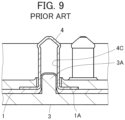
base member 3 toward thehousing 2, as shown inFIG. 9 , aprojection 3A of thebase member 3 is inserted into aprojection accommodating portion 4C of thecontact 4 with theflexible substrate 1 being sandwiched therebetween, and an inner surface of theprojection accommodating portion 4C makes contact with theflexible conductor 1A with a predetermined contact force, whereby thecontact 4 is electrically connected to theflexible conductor 1A. - In addition, as shown in
FIG. 8 , thehousing 2 and thebase member 3 are fixed to each other by press-fitting ahousing fixing post 3B, which is formed to project on thebase member 3, into a post accommodatingportion 2B of thehousing 2. - When a wearable device is fitted with the connector disclosed in
JP 2018-129244 A - However, in the case where the wearable device is disposed apart from a measurement position, it is necessary to constitute an electrical path from the electrode disposed at the measurement position to an attachment position of the connector, and when such an electrical path is formed of the flexible conductor, electric resistance becomes high, and cost increases.
- To cope with it, in order to connect an electrode formed of a flexible conductor to a wearable device by an inexpensive electric wire with low electric resistance, the development of a small-sized connector for connecting a connection object such as an electric wire to a flexible conductor disposed on a garment is desired.
- As a connector of this type, by using a connector having such a configuration that a projection of a base member is inserted into a projection accommodating portion of a contact with a flexible conductor being sandwiched therebetween like the connector disclosed in
JP 2018-129244 A - However, in the connector of
JP 2018-129244 A contact 4 is present, the post accommodatingportion 2B and thehousing fixing post 3B that are for fixing thehousing 2 and thebase member 3 to each other need to be separately disposed at positions away from thecontact 4, and thus it is difficult to reduce a size of the connector. - The present invention has been made to solve the conventional problem described above and aims at providing a connector capable of reducing the size thereof while a conductive connection object is connected to a flexible conductor of a sheet-like conductive member.
- A connector according to the present invention is one in which a connection object having conductivity is connected to a flexible conductor exposed at least on a bottom surface of a sheet-like conductive member having a top surface and the bottom surface facing in opposite directions from each other, the connector comprising:
- a contact having conductivity, being connected to the connection object, and including a tubular portion and a top plate portion of annular shape joined to one end of the tubular portion and provided with a through hole; and
- a housing including a first surface facing the top surface of the sheet-like conductive member, and a contact accommodating portion of recess shape formed in the first surface and accommodating the tubular portion of the contact,
- wherein the housing includes a projection formed to project in the contact accommodating portion from a bottom surface of the contact accommodating portion and penetrating the through hole of the top plate portion joined to the tubular portion accommodated in the contact accommodating portion, and a deformed portion overhanging in a direction along the first surface from a tip of the projection in the tubular portion and covering the top plate portion around the through hole, and
- wherein the top plate portion of the contact is fixed to the housing by the deformed portion of the projection in a state where the first surface of the housing makes contact with the top surface of the sheet-like conductive member and the tubular portion of the contact is accommodated in the contact accommodating portion with the sheet-like conductive member being sandwiched therebetween, and an outer peripheral surface of the tubular portion makes contact with the flexible conductor of the sheet-like conductive member in a direction parallel to the first surface, whereby the connection object is electrically connected to the flexible conductor via the contact.
-
-
FIG. 1 is a perspective view showing a connector according to an embodiment when viewed from an obliquely upper position. -
FIG. 2 is a perspective view showing the connector according to the embodiment when viewed from an obliquely lower position. -
FIG. 3 is a plan view showing the connector according to the embodiment. -
FIG. 4 is a cross-sectional view taken along line A-A inFIG. 3 . -
FIG. 5 is an enlarged view of an important part ofFIG. 4 . -
FIG. 6 is a bottom view showing the connector according to the embodiment in the process of assembling. -
FIG. 7 is a cross-sectional view taken along line B-B inFIG. 6 . -
FIG. 8 is an exploded perspective view showing a conventional connector. -
FIG. 9 is a partial cross-sectional view showing the conventional connector. - An embodiment of the present invention is described below based on the appended drawings.
-
FIGS. 1 and 2 respectively show perspective views of a connector according to the embodiment when viewed from obliquely upper and lower positions. The connector is configured such that a coveredelectric wire 12 being a conductive connection object is connected to a sheet-likeconductive member 11, and includes ahousing 13 made of an insulating resin material, and aconductive contact 14 held by thehousing 13. - The sheet-like
conductive member 11 has a top surface and a bottom surface facing in opposite directions from each other and has aflexible conductor 11A exposed at least on the bottom surface. As the sheet-likeconductive member 11, conductive cloth woven using a conductive thread such as silver can be used, for example. When such conductive cloth is used, theflexible conductor 11A is exposed not only on the bottom surface but also on the top surface of the sheet-likeconductive member 11. In addition, one obtained by applying a conductive ink on a bottom surface of cloth having no conductivity by printing or another method to form theflexible conductor 11A on the bottom surface can also be used as the sheet-likeconductive member 11. Further, a member obtained by forming theflexible conductor 11A formed of a conductive pattern on a bottom surface of an insulating sheet body such as a resin film may be used as the sheet-likeconductive member 11. - The sheet-like
conductive member 11 shown inFIGS. 1 and 2 has a band shape extending in a predetermined direction. - The covered
electric wire 12 has such a structure that an outer periphery of aconductor portion 12A is covered with a coveringportion 12B made of an insulating material. With the connector according to the embodiment, theconductor portion 12A of the coveredelectric wire 12 is electrically connected to theflexible conductor 11A of the sheet-likeconductive member 11. - The covered
electric wire 12 shown inFIGS. 1 and 2 extends in the same direction as the direction in which the sheet-likeconductive member 11 of band shape extends. - The
housing 13 has a flat plate shape extending in parallel to the sheet-likeconductive member 11, and a bottom surface of thehousing 13 is provided with arecessed portion 13A of rectangular shape and alinear groove 13B communicating with therecessed portion 13A. The sheet-likeconductive member 11 and the coveredelectric wire 12 are connected to each other in thehousing 13. - The
contact 14 is accommodated in therecessed portion 13A of thehousing 13 and includes atubular portion 14A of cylindrical shape having a central axis extending in a direction perpendicular to thehousing 13 of flat plate shape, and aflange 14B of annular shape joined to thetubular portion 14A. - In addition, a
crimp terminal portion 15 integrally formed with thecontact 14 is joined to theflange 14B of thecontact 14 and accommodated in thegroove 13B of thehousing 13, and an end portion of the coveredelectric wire 12 is connected to thecrimp terminal portion 15. - For convenience, the predetermined direction in which the sheet-like
conductive member 11 extends toward thehousing 13 is called "+Y direction," the width direction of the sheet-likeconductive member 11 of band shape "X direction," and the direction orthogonal to an XY plane "Z direction." - The sheet-like
conductive member 11 and thehousing 13 extend along an XY plane. Therecessed portion 13A is situated on the -Y direction side on a surface, facing in the -Z direction, of thehousing 13, and thegroove 13B extends in the +Y direction from therecessed portion 13A. A+Y directional end portion of the sheet-likeconductive member 11 is connected to thecontact 14, and a -Y directional end portion of the coveredelectric wire 12 is connected to thecontact 14 via thecrimp terminal portion 15. - As shown in
FIG. 3 , thehousing 13 has a flat shape apparently formed of a rectangular shape situated on the -Y direction side combined with a trapezoidal shape situated on the +Y direction side when viewed in the Z direction, and has an X directional width that is narrower at its +Y directional end portion than at its -Y directional end portion. - As shown in
FIG. 4 that is a cross-sectional view taken along line A-A ofFIG. 3 , a bottom surface, facing in the -Z direction, of therecessed portion 13A of thehousing 13 forms a first surface P1 facing a +Z directional surface of the sheet-likeconductive member 11, and acontact accommodating portion 13C of recess shape recessed in the +Z direction is formed in the first surface P1. - The
housing 13 further includes aprojection 13D formed to project in the -Z direction from a bottom surface, facing in the -Z direction, of thecontact accommodating portion 13C toward the interior of thecontact accommodating portion 13C. - The
tubular potion 14A of thecontact 14 is accommodated in thecontact accommodating portion 13C. Thecontact 14 includes atop plate portion 14C of annular shape joined to a +Z directional end portion of thetubular portion 14A. Thetop plate portion 14C extends from the +Z directional end portion of thetubular portion 14A toward the central axis of thetubular portion 14A along an XY plane, and faces the bottom surface of thecontact accommodating portion 13C. - A cut-out portion (not shown) is formed near the +Y directional end portion of the sheet-like
conductive member 11, and thetubular portion 14A of thecontact 14 is accommodated in thecontact accommodating portion 13C of thehousing 13 while penetrating the cut-out portion of the sheet-likeconductive member 11 from the -Z direction with the sheet-likeconductive member 11 being sandwiched between thetubular portion 14A and thehousing 13. Therefore, the sheet-likeconductive member 11 is sandwiched between an inner peripheral surface of thecontact accommodating portion 13C of thehousing 13 and thetubular portion 14A of thecontact 14. - Note that the
flange 14B of annular shape of thecontact 14 extends from a -Z directional end portion of thetubular portion 14A to the outside of thetubular portion 14A along an XY plane, and thecrimp terminal portion 15 accommodated in thegroove 13B of thehousing 13 is joined to a +Y directional end portion of theflange 14B. In addition, theconductor portion 12A at the -Y directional end portion of the coveredelectric wire 12 is drawn from thecovering portion 12B and crimped with thecrimp terminal portion 15, and accordingly, theconductor portion 12A of the coveredelectric wire 12 is electrically connected to thecontact 14. - As shown in
FIG. 5 that is an enlarged partial view ofFIG. 4 , thetop plate portion 14C of thecontact 14 is provided with a throughhole 14D through which theprojection 13D of thehousing 13 passes. A-Z directional end portion of theprojection 13D is provided with adeformed portion 13E extending to the outside of theprojection 13D along an XY plane. - The
deformed portion 13E overhangs in a direction along an XY plane in thetubular portion 14A of thecontact 14 and covers a surface, facing in the -Z direction, of thetop plate portion 14C around the throughhole 14D. Consequently, thetop plate portion 14C of thecontact 14 is pressed in the +Z direction by thedeformed portion 13E to thereby be fixed with respect to thehousing 13. - While the first surface P1 of the
housing 13 makes contact with the top surface on the +Z direction side of the sheet-likeconductive member 11, and theflexible conductor 11A is exposed at least on the bottom surface on the -Z direction side of the sheet-likeconductive member 11, the sheet-likeconductive member 11 is bent at a right angle at a position where thetubular portion 14A of thecontact 14 is formed, and extends in the +Z direction while being sandwiched between an outer peripheral surface S of thetubular portion 14A and the inner peripheral surface of thecontact accommodating portion 13C of thehousing 13. Accordingly, the outer peripheral surface S of thetubular portion 14A of thecontact 14 comes into contact with theflexible conductor 11A of the sheet-likeconductive member 11 in a direction along an XY plane. - Here, the
contact accommodating portion 13C of thehousing 13 is formed in advance to have an inside diameter slightly smaller than a dimension obtained by adding a double of a thickness of the sheet-likeconductive member 11 to an outside diameter of thetubular portion 14A of thecontact 14; therefore, theflexible conductor 11A of the sheet-likeconductive member 11 is pressed by thecontact accommodating portion 13C against the outer peripheral surface S of thetubular portion 14A of thecontact 14 such that a predetermined contact pressure is applied thereto, whereby thecontact 14 is electrically connected to theflexible conductor 11A. - By inserting the
tubular portion 14A of thecontact 14 from the -Z direction into thecontact accommodating portion 13C of thehousing 13 with the sheet-likeconductive member 11 being sandwiched therebetween when thedeformed portion 13E is not formed at a tip of theprojection 13D of thehousing 13, theprojection 13D is allowed to project in the -Z direction from the throughhole 14D of thetop plate portion 14C of thecontact 14 as shown inFIGS. 6 and 7 , and thereafter, thedeformed portion 13E is formed in thetubular portion 14A of thecontact 14 through heat deformation of the -Z directional end portion of theprojection 13D, whereby the connector as above can be assembled. - Note that the
conductor portion 12A at the -Y directional end portion of the coveredelectric wire 12 is drawn from the coveringportion 12B and crimped with thecrimp terminal portion 15 in advance, and accordingly, theconductor portion 12A of the coveredelectric wire 12 is electrically connected to theflexible conductor 11A of the sheet-likeconductive member 11 via thecontact 14 and thecrimp terminal portion 15. - In the connector of the embodiment, the
top plate portion 14C of thecontact 14 is fixed with respect to thehousing 13 by means of thedeformed portion 13E situated at the -Z directional end portion of theprojection 13D while theflexible conductor 11A of the sheet-likeconductive member 11 and thecontact 14 are electrically connected to each other using thecontact accommodating portion 13C of thehousing 13. Therefore, unlike the connector ofJP 2018-129244 A - In addition, since the
deformed portion 13E that fixes thecontact 14 with respect to thehousing 13 is disposed inside thetubular portion 14A of thecontact 14, particularly, a height size in the Z direction of the connector can be decreased, which makes it possible to obtain a thin connector. - When the connector of the embodiment is applied to smart clothes, and an electrode (not shown) is connected to the
flexible conductor 11A of the sheet-likeconductive member 11, the electrode disposed at a measurement position and a wearable device can be connected to each other by means of the inexpensive coveredelectric wire 12 with low electric resistance. - In the connector of the embodiment, the
top plate portion 14C of thecontact 14 is pressed in the +Z direction by thedeformed portion 13E of thehousing 13, whereby theflange 14B of thecontact 14 can contact, with a predetermined contact pressure, theflexible conductor 11A of the sheet-likeconductive member 11 being in contact with the first surface P1 of thehousing 13. Therefore, thecontact 14 is also electrically connected to theflexible conductor 11A via theflange 14B, whereby the reliability of electric connection between thecontact 14 and theflexible conductor 11A can be improved. - In the embodiment above, the covered
electric wire 12 is connected to thecontact 14 by crimping theconductor portion 12A of the coveredelectric wire 12 to thecrimp terminal portion 15, but the invention is not limited thereto, and the coveredelectric wire 12 can be connected by known various methods such as screw fixing, soldering, welding, and adhesion. - In addition, in the embodiment above, the covered
electric wire 12 is used as a conductive connection object connected to the sheet-likeconductive member 11, but an electric wire having only theconductor portion 12A whose outer periphery is not covered with the coveringportion 12B made of an insulating material may also be used. Further, various conductors such as a conductor of band shape other than an electric wire can be connected to thecontact 14 as a connection object.
Claims (6)
- A connector in which a connection object (12) having conductivity is connected to a flexible conductor (11A) exposed at least on a bottom surface of a sheet-like conductive member (11) having a top surface and the bottom surface facing in opposite directions from each other, the connector comprising:a contact having conductivity, being connected to the connection object, and including a tubular portion (14A) and a top plate portion (14C) of annular shape joined to one end of the tubular portion and provided with a through hole (14D); anda housing (13) including a first surface (P1) facing the top surface of the sheet-like conductive member, and a contact accommodating portion (13C) of recess shape formed in the first surface and accommodating the tubular portion of the contact,wherein the housing (13) includes a projection (13D) formed to project in the contact accommodating portion from a bottom surface of the contact accommodating portion and penetrating the through hole of the top plate portion joined to the tubular portion accommodated in the contact accommodating portion, and a deformed portion (13E) overhanging in a direction along the first surface from a tip of the projection in the tubular portion and covering the top plate portion around the through hole, andwherein the top plate portion of the contact is fixed to the housing by the deformed portion of the projection in a state where the first surface of the housing makes contact with the top surface of the sheet-like conductive member and the tubular portion of the contact is accommodated in the contact accommodating portion with the sheet-like conductive member being sandwiched therebetween, and an outer peripheral surface of the tubular portion makes contact with the flexible conductor of the sheet-like conductive member in a direction parallel to the first surface, whereby the connection object is electrically connected to the flexible conductor via the contact.
- The connector according to claim 1, wherein the contact accommodating portion (13C) of the housing has an inside diameter slightly smaller than a dimension obtained by adding a double of a thickness of the sheet-like conductive member (11) to an outside diameter of the tubular portion (14A) of the contact.
- The connector according to claim 1 or 2,wherein the contact (14) includes a flange (14B) joined to another end of the tubular portion and extending in a direction along the first surface of the housing, andwherein the flange makes contact with the flexible conductor (11A) of the sheet-like conductive member.
- The connector according to claim 3, comprising a crimp terminal portion (15) joined to the flange (14B) and to be connected with the connection object.
- The connector according to any one of claims 1-4, wherein the connection object is composed of an electric wire (12).
- The connector according to any one of claims 1-5, wherein the housing (13) is made of an insulating resin material.
Applications Claiming Priority (1)
| Application Number | Priority Date | Filing Date | Title |
|---|---|---|---|
| JP2022020351A JP2023117663A (en) | 2022-02-14 | 2022-02-14 | connector |
Publications (2)
| Publication Number | Publication Date |
|---|---|
| EP4228099A1 true EP4228099A1 (en) | 2023-08-16 |
| EP4228099B1 EP4228099B1 (en) | 2024-10-16 |
Family
ID=84799955
Family Applications (1)
| Application Number | Title | Priority Date | Filing Date |
|---|---|---|---|
| EP23150085.1A Active EP4228099B1 (en) | 2022-02-14 | 2023-01-03 | Connector |
Country Status (4)
| Country | Link |
|---|---|
| US (1) | US20230261415A1 (en) |
| EP (1) | EP4228099B1 (en) |
| JP (1) | JP2023117663A (en) |
| CN (1) | CN116598806A (en) |
Citations (3)
| Publication number | Priority date | Publication date | Assignee | Title |
|---|---|---|---|---|
| JP2018129244A (en) | 2017-02-10 | 2018-08-16 | 日本航空電子工業株式会社 | connector |
| US20200025590A1 (en) * | 2016-10-11 | 2020-01-23 | Kabushiki Kaisha Tokai Rika Deniki Seisakusho | Connection structure, touch sensor and method for forming connection structure |
| US20200235536A1 (en) * | 2019-01-22 | 2020-07-23 | Japan Aviation Electronics Industry, Limited | Coated conductive wire connecting method, coated conductive wire connecting structure and coated conductive wire connecting member |
Family Cites Families (8)
| Publication number | Priority date | Publication date | Assignee | Title |
|---|---|---|---|---|
| US6394833B1 (en) * | 2001-04-25 | 2002-05-28 | Miraco, Inc. | Flat flexible cable connector |
| JP4576226B2 (en) * | 2004-12-28 | 2010-11-04 | ホシデン株式会社 | Coaxial connector integrated board connection connector |
| JP5893955B2 (en) * | 2012-02-27 | 2016-03-23 | 株式会社神戸製鋼所 | Method for manufacturing fastening structure of foamed resin core composite plate |
| FR3023421B1 (en) * | 2014-07-04 | 2018-03-02 | Idz Concept | SUPPORT SUPPORT FOR ELECTRIC CABLE COMPONENT |
| CN106505363B (en) * | 2016-12-23 | 2019-11-26 | 深圳市泰科汉泽精密电子有限公司 | Magnetic pole button |
| JP7265458B2 (en) * | 2019-09-26 | 2023-04-26 | 日本航空電子工業株式会社 | Connector and connection method |
| US12191589B2 (en) * | 2020-07-09 | 2025-01-07 | Aptiv Technologies AG | Solder coated rivet electrical connector |
| JP7748880B2 (en) * | 2022-01-12 | 2025-10-03 | 日本航空電子工業株式会社 | connector |
-
2022
- 2022-02-14 JP JP2022020351A patent/JP2023117663A/en active Pending
- 2022-12-29 CN CN202211713025.7A patent/CN116598806A/en active Pending
-
2023
- 2023-01-03 US US18/149,626 patent/US20230261415A1/en not_active Abandoned
- 2023-01-03 EP EP23150085.1A patent/EP4228099B1/en active Active
Patent Citations (3)
| Publication number | Priority date | Publication date | Assignee | Title |
|---|---|---|---|---|
| US20200025590A1 (en) * | 2016-10-11 | 2020-01-23 | Kabushiki Kaisha Tokai Rika Deniki Seisakusho | Connection structure, touch sensor and method for forming connection structure |
| JP2018129244A (en) | 2017-02-10 | 2018-08-16 | 日本航空電子工業株式会社 | connector |
| US20200235536A1 (en) * | 2019-01-22 | 2020-07-23 | Japan Aviation Electronics Industry, Limited | Coated conductive wire connecting method, coated conductive wire connecting structure and coated conductive wire connecting member |
Also Published As
| Publication number | Publication date |
|---|---|
| EP4228099B1 (en) | 2024-10-16 |
| CN116598806A (en) | 2023-08-15 |
| JP2023117663A (en) | 2023-08-24 |
| US20230261415A1 (en) | 2023-08-17 |
Similar Documents
| Publication | Publication Date | Title |
|---|---|---|
| EP3435490B1 (en) | Connection assisting member and circuit board assembly | |
| US20230223717A1 (en) | Connector | |
| US20180269606A1 (en) | Connector | |
| US11710922B2 (en) | Connector | |
| EP4340135B1 (en) | Connector | |
| EP4346017A1 (en) | Connector | |
| US12230907B2 (en) | Electrical connector for connecting an electric wire to a flat flexible conductor and an electrical connector assembly therefor | |
| EP4228099B1 (en) | Connector | |
| US10862254B2 (en) | Coated conductive wire connecting method, coated conductive wire connecting structure and coated conductive wire connecting member | |
| US20240088590A1 (en) | Connector | |
| EP4462605B1 (en) | Connector | |
| CN118117364A (en) | Connector assembly and connection method | |
| EP4343974A1 (en) | Connector | |
| JP7822294B2 (en) | Connector, connector assembly, and connection method | |
| US20240145955A1 (en) | Connector and connector assembly | |
| JP2024178974A (en) | Connector and connector assembly | |
| JP2000100506A (en) | connector |
Legal Events
| Date | Code | Title | Description |
|---|---|---|---|
| PUAI | Public reference made under article 153(3) epc to a published international application that has entered the european phase |
Free format text: ORIGINAL CODE: 0009012 |
|
| STAA | Information on the status of an ep patent application or granted ep patent |
Free format text: STATUS: REQUEST FOR EXAMINATION WAS MADE |
|
| 17P | Request for examination filed |
Effective date: 20230103 |
|
| AK | Designated contracting states |
Kind code of ref document: A1 Designated state(s): AL AT BE BG CH CY CZ DE DK EE ES FI FR GB GR HR HU IE IS IT LI LT LU LV MC ME MK MT NL NO PL PT RO RS SE SI SK SM TR |
|
| RBV | Designated contracting states (corrected) |
Designated state(s): AL AT BE BG CH CY CZ DE DK EE ES FI FR GB GR HR HU IE IS IT LI LT LU LV MC ME MK MT NL NO PL PT RO RS SE SI SK SM TR |
|
| STAA | Information on the status of an ep patent application or granted ep patent |
Free format text: STATUS: EXAMINATION IS IN PROGRESS |
|
| 17Q | First examination report despatched |
Effective date: 20231201 |
|
| GRAP | Despatch of communication of intention to grant a patent |
Free format text: ORIGINAL CODE: EPIDOSNIGR1 |
|
| STAA | Information on the status of an ep patent application or granted ep patent |
Free format text: STATUS: GRANT OF PATENT IS INTENDED |
|
| RIC1 | Information provided on ipc code assigned before grant |
Ipc: H01R 4/18 20060101ALN20240503BHEP Ipc: H01R 12/81 20110101ALI20240503BHEP Ipc: H01R 12/65 20110101ALI20240503BHEP Ipc: H01R 9/22 20060101AFI20240503BHEP |
|
| INTG | Intention to grant announced |
Effective date: 20240529 |
|
| GRAS | Grant fee paid |
Free format text: ORIGINAL CODE: EPIDOSNIGR3 |
|
| GRAA | (expected) grant |
Free format text: ORIGINAL CODE: 0009210 |
|
| STAA | Information on the status of an ep patent application or granted ep patent |
Free format text: STATUS: THE PATENT HAS BEEN GRANTED |
|
| AK | Designated contracting states |
Kind code of ref document: B1 Designated state(s): AL AT BE BG CH CY CZ DE DK EE ES FI FR GB GR HR HU IE IS IT LI LT LU LV MC ME MK MT NL NO PL PT RO RS SE SI SK SM TR |
|
| RAP3 | Party data changed (applicant data changed or rights of an application transferred) |
Owner name: JAPAN AVIATION ELECTRONICS INDUSTRY, LIMITED |
|
| REG | Reference to a national code |
Ref country code: GB Ref legal event code: FG4D |
|
| REG | Reference to a national code |
Ref country code: CH Ref legal event code: EP |
|
| REG | Reference to a national code |
Ref country code: IE Ref legal event code: FG4D |
|
| REG | Reference to a national code |
Ref country code: DE Ref legal event code: R096 Ref document number: 602023000706 Country of ref document: DE |
|
| REG | Reference to a national code |
Ref country code: LT Ref legal event code: MG9D |
|
| REG | Reference to a national code |
Ref country code: NL Ref legal event code: MP Effective date: 20241016 |
|
| REG | Reference to a national code |
Ref country code: AT Ref legal event code: MK05 Ref document number: 1733717 Country of ref document: AT Kind code of ref document: T Effective date: 20241016 |
|
| PG25 | Lapsed in a contracting state [announced via postgrant information from national office to epo] |
Ref country code: NL Free format text: LAPSE BECAUSE OF FAILURE TO SUBMIT A TRANSLATION OF THE DESCRIPTION OR TO PAY THE FEE WITHIN THE PRESCRIBED TIME-LIMIT Effective date: 20241016 |
|
| PG25 | Lapsed in a contracting state [announced via postgrant information from national office to epo] |
Ref country code: NL Free format text: LAPSE BECAUSE OF FAILURE TO SUBMIT A TRANSLATION OF THE DESCRIPTION OR TO PAY THE FEE WITHIN THE PRESCRIBED TIME-LIMIT Effective date: 20241016 |
|
| PG25 | Lapsed in a contracting state [announced via postgrant information from national office to epo] |
Ref country code: PT Free format text: LAPSE BECAUSE OF FAILURE TO SUBMIT A TRANSLATION OF THE DESCRIPTION OR TO PAY THE FEE WITHIN THE PRESCRIBED TIME-LIMIT Effective date: 20250217 Ref country code: IS Free format text: LAPSE BECAUSE OF FAILURE TO SUBMIT A TRANSLATION OF THE DESCRIPTION OR TO PAY THE FEE WITHIN THE PRESCRIBED TIME-LIMIT Effective date: 20250216 Ref country code: HR Free format text: LAPSE BECAUSE OF FAILURE TO SUBMIT A TRANSLATION OF THE DESCRIPTION OR TO PAY THE FEE WITHIN THE PRESCRIBED TIME-LIMIT Effective date: 20241016 |
|
| PGFP | Annual fee paid to national office [announced via postgrant information from national office to epo] |
Ref country code: DE Payment date: 20250110 Year of fee payment: 3 |
|
| PG25 | Lapsed in a contracting state [announced via postgrant information from national office to epo] |
Ref country code: FI Free format text: LAPSE BECAUSE OF FAILURE TO SUBMIT A TRANSLATION OF THE DESCRIPTION OR TO PAY THE FEE WITHIN THE PRESCRIBED TIME-LIMIT Effective date: 20241016 |
|
| PG25 | Lapsed in a contracting state [announced via postgrant information from national office to epo] |
Ref country code: BG Free format text: LAPSE BECAUSE OF FAILURE TO SUBMIT A TRANSLATION OF THE DESCRIPTION OR TO PAY THE FEE WITHIN THE PRESCRIBED TIME-LIMIT Effective date: 20241016 |
|
| PG25 | Lapsed in a contracting state [announced via postgrant information from national office to epo] |
Ref country code: ES Free format text: LAPSE BECAUSE OF FAILURE TO SUBMIT A TRANSLATION OF THE DESCRIPTION OR TO PAY THE FEE WITHIN THE PRESCRIBED TIME-LIMIT Effective date: 20241016 |
|
| PG25 | Lapsed in a contracting state [announced via postgrant information from national office to epo] |
Ref country code: NO Free format text: LAPSE BECAUSE OF FAILURE TO SUBMIT A TRANSLATION OF THE DESCRIPTION OR TO PAY THE FEE WITHIN THE PRESCRIBED TIME-LIMIT Effective date: 20250116 |
|
| PG25 | Lapsed in a contracting state [announced via postgrant information from national office to epo] |
Ref country code: LV Free format text: LAPSE BECAUSE OF FAILURE TO SUBMIT A TRANSLATION OF THE DESCRIPTION OR TO PAY THE FEE WITHIN THE PRESCRIBED TIME-LIMIT Effective date: 20241016 Ref country code: AT Free format text: LAPSE BECAUSE OF FAILURE TO SUBMIT A TRANSLATION OF THE DESCRIPTION OR TO PAY THE FEE WITHIN THE PRESCRIBED TIME-LIMIT Effective date: 20241016 Ref country code: GR Free format text: LAPSE BECAUSE OF FAILURE TO SUBMIT A TRANSLATION OF THE DESCRIPTION OR TO PAY THE FEE WITHIN THE PRESCRIBED TIME-LIMIT Effective date: 20250117 |
|
| PG25 | Lapsed in a contracting state [announced via postgrant information from national office to epo] |
Ref country code: PL Free format text: LAPSE BECAUSE OF FAILURE TO SUBMIT A TRANSLATION OF THE DESCRIPTION OR TO PAY THE FEE WITHIN THE PRESCRIBED TIME-LIMIT Effective date: 20241016 |
|
| PG25 | Lapsed in a contracting state [announced via postgrant information from national office to epo] |
Ref country code: RS Free format text: LAPSE BECAUSE OF FAILURE TO SUBMIT A TRANSLATION OF THE DESCRIPTION OR TO PAY THE FEE WITHIN THE PRESCRIBED TIME-LIMIT Effective date: 20250116 |
|
| PG25 | Lapsed in a contracting state [announced via postgrant information from national office to epo] |
Ref country code: SM Free format text: LAPSE BECAUSE OF FAILURE TO SUBMIT A TRANSLATION OF THE DESCRIPTION OR TO PAY THE FEE WITHIN THE PRESCRIBED TIME-LIMIT Effective date: 20241016 |
|
| PG25 | Lapsed in a contracting state [announced via postgrant information from national office to epo] |
Ref country code: DK Free format text: LAPSE BECAUSE OF FAILURE TO SUBMIT A TRANSLATION OF THE DESCRIPTION OR TO PAY THE FEE WITHIN THE PRESCRIBED TIME-LIMIT Effective date: 20241016 |
|
| REG | Reference to a national code |
Ref country code: DE Ref legal event code: R097 Ref document number: 602023000706 Country of ref document: DE |
|
| PG25 | Lapsed in a contracting state [announced via postgrant information from national office to epo] |
Ref country code: EE Free format text: LAPSE BECAUSE OF FAILURE TO SUBMIT A TRANSLATION OF THE DESCRIPTION OR TO PAY THE FEE WITHIN THE PRESCRIBED TIME-LIMIT Effective date: 20241016 |
|
| PG25 | Lapsed in a contracting state [announced via postgrant information from national office to epo] |
Ref country code: RO Free format text: LAPSE BECAUSE OF FAILURE TO SUBMIT A TRANSLATION OF THE DESCRIPTION OR TO PAY THE FEE WITHIN THE PRESCRIBED TIME-LIMIT Effective date: 20241016 |
|
| PG25 | Lapsed in a contracting state [announced via postgrant information from national office to epo] |
Ref country code: SK Free format text: LAPSE BECAUSE OF FAILURE TO SUBMIT A TRANSLATION OF THE DESCRIPTION OR TO PAY THE FEE WITHIN THE PRESCRIBED TIME-LIMIT Effective date: 20241016 |
|
| PG25 | Lapsed in a contracting state [announced via postgrant information from national office to epo] |
Ref country code: CZ Free format text: LAPSE BECAUSE OF FAILURE TO SUBMIT A TRANSLATION OF THE DESCRIPTION OR TO PAY THE FEE WITHIN THE PRESCRIBED TIME-LIMIT Effective date: 20241016 |
|
| PG25 | Lapsed in a contracting state [announced via postgrant information from national office to epo] |
Ref country code: IT Free format text: LAPSE BECAUSE OF FAILURE TO SUBMIT A TRANSLATION OF THE DESCRIPTION OR TO PAY THE FEE WITHIN THE PRESCRIBED TIME-LIMIT Effective date: 20241016 |
|
| PLBE | No opposition filed within time limit |
Free format text: ORIGINAL CODE: 0009261 |
|
| STAA | Information on the status of an ep patent application or granted ep patent |
Free format text: STATUS: NO OPPOSITION FILED WITHIN TIME LIMIT |
|
| PG25 | Lapsed in a contracting state [announced via postgrant information from national office to epo] |
Ref country code: SE Free format text: LAPSE BECAUSE OF FAILURE TO SUBMIT A TRANSLATION OF THE DESCRIPTION OR TO PAY THE FEE WITHIN THE PRESCRIBED TIME-LIMIT Effective date: 20241016 |
|
| PG25 | Lapsed in a contracting state [announced via postgrant information from national office to epo] |
Ref country code: MC Free format text: LAPSE BECAUSE OF FAILURE TO SUBMIT A TRANSLATION OF THE DESCRIPTION OR TO PAY THE FEE WITHIN THE PRESCRIBED TIME-LIMIT Effective date: 20241016 Ref country code: LU Free format text: LAPSE BECAUSE OF NON-PAYMENT OF DUE FEES Effective date: 20250103 |
|
| 26N | No opposition filed |
Effective date: 20250717 |
|
| PG25 | Lapsed in a contracting state [announced via postgrant information from national office to epo] |
Ref country code: BE Free format text: LAPSE BECAUSE OF NON-PAYMENT OF DUE FEES Effective date: 20250131 |
|
| PG25 | Lapsed in a contracting state [announced via postgrant information from national office to epo] |
Ref country code: FR Free format text: LAPSE BECAUSE OF NON-PAYMENT OF DUE FEES Effective date: 20250131 |
|
| REG | Reference to a national code |
Ref country code: BE Ref legal event code: MM Effective date: 20250131 |
|
| PG25 | Lapsed in a contracting state [announced via postgrant information from national office to epo] |
Ref country code: IE Free format text: LAPSE BECAUSE OF NON-PAYMENT OF DUE FEES Effective date: 20250103 |
|
| PG25 | Lapsed in a contracting state [announced via postgrant information from national office to epo] |
Ref country code: CY Free format text: LAPSE BECAUSE OF FAILURE TO SUBMIT A TRANSLATION OF THE DESCRIPTION OR TO PAY THE FEE WITHIN THE PRESCRIBED TIME-LIMIT Effective date: 20241016 |
|
| PG25 | Lapsed in a contracting state [announced via postgrant information from national office to epo] |
Ref country code: TR Free format text: LAPSE BECAUSE OF FAILURE TO SUBMIT A TRANSLATION OF THE DESCRIPTION OR TO PAY THE FEE WITHIN THE PRESCRIBED TIME-LIMIT Effective date: 20241016 |
|
| PG25 | Lapsed in a contracting state [announced via postgrant information from national office to epo] |
Ref country code: LT Free format text: LAPSE BECAUSE OF FAILURE TO SUBMIT A TRANSLATION OF THE DESCRIPTION OR TO PAY THE FEE WITHIN THE PRESCRIBED TIME-LIMIT Effective date: 20241016 |