EP4228097A1 - Operating mode indication method, apparatus, and device - Google Patents
Operating mode indication method, apparatus, and device Download PDFInfo
- Publication number
- EP4228097A1 EP4228097A1 EP21888670.3A EP21888670A EP4228097A1 EP 4228097 A1 EP4228097 A1 EP 4228097A1 EP 21888670 A EP21888670 A EP 21888670A EP 4228097 A1 EP4228097 A1 EP 4228097A1
- Authority
- EP
- European Patent Office
- Prior art keywords
- working mode
- ris
- relay
- moment
- information
- Prior art date
- Legal status (The legal status is an assumption and is not a legal conclusion. Google has not performed a legal analysis and makes no representation as to the accuracy of the status listed.)
- Pending
Links
Images
Classifications
-
- H—ELECTRICITY
- H04—ELECTRIC COMMUNICATION TECHNIQUE
- H04B—TRANSMISSION
- H04B7/00—Radio transmission systems, i.e. using radiation field
- H04B7/14—Relay systems
- H04B7/15—Active relay systems
- H04B7/155—Ground-based stations
- H04B7/15557—Selecting relay station operation mode, e.g. between amplify and forward mode, decode and forward mode or FDD - and TDD mode
-
- H—ELECTRICITY
- H04—ELECTRIC COMMUNICATION TECHNIQUE
- H04L—TRANSMISSION OF DIGITAL INFORMATION, e.g. TELEGRAPHIC COMMUNICATION
- H04L5/00—Arrangements affording multiple use of the transmission path
- H04L5/003—Arrangements for allocating sub-channels of the transmission path
- H04L5/0053—Allocation of signalling, i.e. of overhead other than pilot signals
-
- H—ELECTRICITY
- H04—ELECTRIC COMMUNICATION TECHNIQUE
- H04B—TRANSMISSION
- H04B7/00—Radio transmission systems, i.e. using radiation field
- H04B7/02—Diversity systems; Multi-antenna system, i.e. transmission or reception using multiple antennas
- H04B7/04—Diversity systems; Multi-antenna system, i.e. transmission or reception using multiple antennas using two or more spaced independent antennas
- H04B7/04013—Intelligent reflective surfaces
-
- H—ELECTRICITY
- H01—ELECTRIC ELEMENTS
- H01Q—ANTENNAS, i.e. RADIO AERIALS
- H01Q15/00—Devices for reflection, refraction, diffraction or polarisation of waves radiated from an antenna, e.g. quasi-optical devices
- H01Q15/0006—Devices acting selectively as reflecting surface, as diffracting or as refracting device, e.g. frequency filtering or angular spatial filtering devices
- H01Q15/0013—Devices acting selectively as reflecting surface, as diffracting or as refracting device, e.g. frequency filtering or angular spatial filtering devices said selective devices working as frequency-selective reflecting surfaces, e.g. FSS, dichroic plates, surfaces being partly transmissive and reflective
- H01Q15/002—Devices acting selectively as reflecting surface, as diffracting or as refracting device, e.g. frequency filtering or angular spatial filtering devices said selective devices working as frequency-selective reflecting surfaces, e.g. FSS, dichroic plates, surfaces being partly transmissive and reflective said selective devices being reconfigurable or tunable, e.g. using switches or diodes
-
- H—ELECTRICITY
- H01—ELECTRIC ELEMENTS
- H01Q—ANTENNAS, i.e. RADIO AERIALS
- H01Q15/00—Devices for reflection, refraction, diffraction or polarisation of waves radiated from an antenna, e.g. quasi-optical devices
- H01Q15/0006—Devices acting selectively as reflecting surface, as diffracting or as refracting device, e.g. frequency filtering or angular spatial filtering devices
- H01Q15/0086—Devices acting selectively as reflecting surface, as diffracting or as refracting device, e.g. frequency filtering or angular spatial filtering devices said selective devices having materials with a synthesized negative refractive index, e.g. metamaterials or left-handed materials
-
- H—ELECTRICITY
- H01—ELECTRIC ELEMENTS
- H01Q—ANTENNAS, i.e. RADIO AERIALS
- H01Q3/00—Arrangements for changing or varying the orientation or the shape of the directional pattern of the waves radiated from an antenna or antenna system
- H01Q3/44—Arrangements for changing or varying the orientation or the shape of the directional pattern of the waves radiated from an antenna or antenna system varying the electric or magnetic characteristics of reflecting, refracting, or diffracting devices associated with the radiating element
- H01Q3/46—Active lenses or reflecting arrays
-
- H—ELECTRICITY
- H04—ELECTRIC COMMUNICATION TECHNIQUE
- H04B—TRANSMISSION
- H04B1/00—Details of transmission systems, not covered by a single one of groups H04B3/00 - H04B13/00; Details of transmission systems not characterised by the medium used for transmission
- H04B1/38—Transceivers, i.e. devices in which transmitter and receiver form a structural unit and in which at least one part is used for functions of transmitting and receiving
- H04B1/40—Circuits
- H04B1/401—Circuits for selecting or indicating operating mode
-
- H—ELECTRICITY
- H04—ELECTRIC COMMUNICATION TECHNIQUE
- H04L—TRANSMISSION OF DIGITAL INFORMATION, e.g. TELEGRAPHIC COMMUNICATION
- H04L5/00—Arrangements affording multiple use of the transmission path
- H04L5/0001—Arrangements for dividing the transmission path
- H04L5/0014—Three-dimensional division
- H04L5/0023—Time-frequency-space
-
- H—ELECTRICITY
- H04—ELECTRIC COMMUNICATION TECHNIQUE
- H04L—TRANSMISSION OF DIGITAL INFORMATION, e.g. TELEGRAPHIC COMMUNICATION
- H04L5/00—Arrangements affording multiple use of the transmission path
- H04L5/003—Arrangements for allocating sub-channels of the transmission path
- H04L5/0048—Allocation of pilot signals, i.e. of signals known to the receiver
Definitions
- the present application belongs to the field of communication technologies, and specifically relates to a method and an apparatus for indicating a working mode of a reconfigurable intelligent surface (RIS) and a device.
- RIS reconfigurable intelligent surface
- An intelligent surface device consists of a massive device array and an array control module.
- the massive device array is a large amount of device units that are regularly and repeatedly arranged on a planar baseboard. To achieve a considerable signal control effect, hundreds or thousands of device units are usually required to form the device array.
- Each device unit has a variable device structure.
- the device unit includes a positive-intrinsic-negative (PIN) diode, and a response mode of the device unit for an external wireless signal depends on a switch state of the PIN diode.
- the array control module of the intelligent surface may control a working state of each device unit, to dynamically or semi-statically control a response mode of each device unit for a wireless signal.
- Wireless response signals of the device units of the massive device array are superposed to each other, forming a specified beam propagation feature in a macro sense.
- the control module is a "brain" of the intelligent surface device, and determines a wireless signal response beam of the intelligent surface according to a requirement of a communications system, so that an original static communication environment becomes “intelligent” and “controllable”.
- a working mode of the RIS corresponds to the emission or transmission effect of the RIS on an incident signal, and the emission or transmission effect can be controlled by switch patterns of diodes corresponding to all units of the RIS.
- the switch patterns of diodes corresponding to all units of each RIS correspond to a working mode of the RIS.
- a base station sends a signal to the RIS, and the RIS reflects the signal to the terminal. If the signal is transmitted from the UE, the base station can also receive the signal transmitted by the RIS. That is, the RIS working mode has uplink and downlink symmetry. However, the uplink and downlink symmetry of the RIS working mode affects downlink signal reception and uplink signal transmission of the same terminal. Similarly, there are similar problems in a relay working mode.
- the purpose of the embodiments of the present application is to provide a working mode indicating method and apparatus and device, so as to indicate the working mode of the RIS or the relay.
- a working mode indicating method performed by a first device, where the first device is a terminal, or the first device is an RIS node or a relay node.
- the method includes: receiving first information sent by a network side device, where the first information indicates an RIS working mode or a relay working mode.
- a working mode indicating method performed by a network side device, including: sending first information, where the first information indicates an RIS working mode or a relay working mode.
- a working mode indicating apparatus including: a first receiving module, configured to receive first information, where the first information indicates an RIS working mode or a relay working mode.
- a working mode indicating apparatus including: a first sending module, configured to send first information, where the first information indicates an RIS working mode or a relay working mode.
- a first device is a terminal, or the first device is an RIS node or a relay node, including: a processor, a memory, and a program stored in the memory and executable on the processor, and when the program is executed by the processor, step of the method according to the first aspect is performed.
- a network side device in a sixth aspect, there is provided a network side device.
- the network side device includes: a processor, a memory, and a program stored in the memory and executable on the processor, and when the program is executed by the processor, step of the method according to the second aspect is performed.
- a readable storage medium stores a program or an instruction, and when the program or the instruction is executed by a processor, step of the method according to the first aspect or the second aspect is performed.
- a computer program product is provided, the computer program product is stored in a non-volatile storage medium, and when the computer program product is executed by at least one processor, step of the method according to the first aspect or the second aspect is performed.
- a chip in a ninth aspect, includes a processor and a communication interface, the communication interface is coupled to the processor, and the processor is used to run programs or instructions, so as to implement the processing method according to the first aspect or the second aspect.
- the network side indicates the RIS working mode or the relay working mode, so that the uplink transmission and downlink reception of the same terminal use the same RIS working mode or the relay working mode, which solves the impact of the uplink and downlink symmetry of the RIS working mode or the relay working mode on the downlink signal reception and uplink signal transmission of the same terminal.
- first, second, and the like in the specification and claims of the present application are used to distinguish between similar objects instead of describing a designated order or sequence. It should be understood that, data used in this way is interchangeable in proper circumstances, so that the embodiments of the present application can be implemented in an order other than the order illustrated or described herein.
- Objects classified by “first” and “second” are usually of a same type, and the number of objects is not limited. For example, there may be one or more first objects.
- “and” in the specification and claims represents at least one of connected objects. Symbol “/" generally represents an "or" relationship between associated objects.
- the technologies described in the embodiments of the present application are not limited to a Long Term Evolution (Long Term Evolution, LTE)/LTE-Advanced (LTE-Advanced, LTE-A) system, and can also be used in other wireless communications systems such as Code Division Multiple Access (Code Division Multiple Access, CDMA), Time Division Multiple Access (Time Division Multiple Access, TDMA), Frequency Division Multiple Access (Frequency Division Multiple Access, FDMA), Orthogonal Frequency Division Multiple Access (Orthogonal Frequency Division Multiple Access, OFDMA), Single-carrier Frequency-Division Multiple Access (Single-carrier Frequency-Division Multiple Access, SC-FDMA), and another system.
- Code Division Multiple Access Code Division Multiple Access
- CDMA Code Division Multiple Access
- Time Division Multiple Access Time Division Multiple Access
- FDMA Frequency Division Multiple Access
- OFDMA Orthogonal Frequency Division Multiple Access
- SC-FDMA Single-carrier Frequency-Division Multiple Access
- system and “network” in the embodiments of the present application may be used interchangeably.
- the described technologies can be applied to both the systems and the radio technologies mentioned above as well as to other systems and radio technologies.
- a new radio (New Radio, NR) system is described in the following description for illustrative purposes, and the NR terminology is used in most of the following description, although these technologies can also be applied to applications other than the NR system application, such as the 6th generation (6 th Generation, 6G) communications system.
- 6th generation 6 th Generation, 6G
- the intelligent surface includes tunable resonator (Tunable Resonator) variable capacitance type, guided wave (Guided Wave) waveguide type, element rotation (Element Rotation) polarization type, and the like.
- the intelligent surface is divided into reflection Type intelligent surface and transmission type intelligent surface.
- the intelligent surface includes phase control intelligent surface, amplitude control intelligent surface, and amplitude phase joint control intelligent surface.
- response parameter control the intelligent surface is divided into continuous control type and discrete control type.
- the intelligent surface can be divided into statically, semi-statically, or dynamically controlled intelligent surfaces, where static intelligent surfaces can be applied to existing systems at present, for example, the fourth generation mobile communication technology (4G)/fifth-generation mobile communication technology (5G) system.
- 4G fourth generation mobile communication technology
- 5G fifth-generation mobile communication technology
- the intelligent reflecting surface that is widely discussed in the academic circle is a phase-controlled intelligent surface based on signal reflection. The phase change of 0 or ⁇ is realized by controlling the phase of the reflected signal of the device unit with indication information of 1 bit.
- the intelligent surface device Since radio frequency and baseband processing circuits are not required, the intelligent surface device has several advantages over a conventional wireless communication transceiver device:
- RIS reflection units The types of RIS reflection units are as follows:
- Reflect arrays/intelligent surfaces can be classified into two types according to whether dynamic control can be performed:
- the intelligent surface includes a large number of device units and has no radio frequency and baseband processing capabilities, this type of intelligent surface is called a passive intelligent surface.
- the base station Since the intelligent surface is composed of a large amount of component units and does not have a radio frequency and baseband processing capability, the base station cannot separately obtain channel information from the base station to the intelligent surface and from the intelligent surface to the terminal.
- a receive signal of the base station or the terminal is formed by superimposing response signals of a large amount of component units of the intelligent surface, and changing a working state of one component unit or a small amount of component units does not cause a significant change of the receive signal.
- a possible measurement scheme is to install a small amount of active component units in the intelligent surface, so that the intelligent surface can perform channel measurement and feedback.
- the base station calculates a reasonable intelligent surface configuration parameter from limited channel information by using a compression sensing or deep learning algorithm.
- An intelligent surface-based communications system needs an efficient channel measurement mechanism, to improve end-to-end signal quality as much as possible while ensuring low complexity of the intelligent surface.
- This intelligent surface on which some active components are installed has a capability of receiving and even sending a signal, and is an active and passive intelligent surface (or an active intelligent surface).
- a working mode of the RIS corresponds to the emission or transmission effect of the RIS on an incident signal, and the emission or transmission effect can be controlled by switch patterns of diodes corresponding to all units of the RIS.
- the switch patterns of diodes corresponding to all units of each RIS correspond to a working mode of the RIS.
- an RIS can only work in one mode at a time.
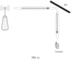
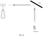
- a base station sends a signal to an RIS, and the RIS reflects the signal to a terminal. At this time, the RIS works in working mode 1.
- the base station can also receive the signal transmitted through the RIS.
- the reflection effect of the RIS on the incident signal is symmetrical or equivalent to some extent.
- the fifth-generation mobile communication technology allocates uplink and downlink resource ratios in units of slots (Slots) or even orthogonal frequency division multiplex (OFDM) symbols.
- the communication system supports the use of cell-specific (Cell specific) and terminal-specific (UE specific) radio resource control (Radio Resource Control, RRC) signaling to indicate uplink and downlink subframe ratios of UEs.
- Cell specific Cell specific
- UE specific terminal-specific
- RRC Radio Resource Control
- the communication system supports flexible adjustment of uplink and downlink resource ratios through downlink control information (DCI) signaling, and 55 standardized structures are predefined (a maximum of 254 structures are reserved).
- DCI downlink control information
- D means that the symbol is a downlink symbol
- U means that the symbol is an uplink symbol
- F means that the symbol is a flexible symbol (that is, it is not sure whether it is an uplink or downlink symbol).
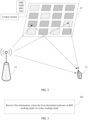
- FIG. 2 is a block diagram of a wireless communications system to which embodiments of the present application can be applied.
- the wireless communication system includes a terminal 21, a network side device 22, and an intelligent surface device 23.
- the terminal 21 may also be called a terminal device or user equipment (UE), and the terminal 21 may be a mobile phone, a tablet personal computer (Tablet Personal Computer), a laptop computer (Laptop Computer) or a notebook computer, a personal digital Assistant (PDA), a palmtop computer, a netbook, an ultra-mobile personal computer (UMPC), a mobile Internet device (MID), a wearable device (Wearable Device) or a vehicle-mounted device (VUE), a pedestrian terminal (PUE), and other terminal side devices.
- the wearable device includes: bracelets, earphones, glasses, etc. It should be noted that a specific type of the terminal 21 is not limited in the embodiments of the present application.
- the network side device 22 may be a base station or a core network.
- the base station may be referred to as a node B, an evolved node B, an access point, a base transceiver station (BTS), a radio base station, a radio transceiver, a basic service set (BSS), an extended service set (ESS), a node B, an evolved node B (eNB), a home node B, a home evolved node B, a wireless local area network (WLAN) access point, a wireless fidelity (WiFi) node, a transmitting receiving point (TRP), a wireless access network node, or other appropriate terms in the art.
- the base station is not limited to a specified technical term. It should be noted that, in embodiments of the present application, only a base station in the NR system is used as an example, but a specific type of the base station is not limited.
- an embodiment of the present application provides a working mode indicating method, executed by a first device.
- the first device is a terminal, or the first device is an RIS node or a relay node, for example, a layer 1 relay, a layer 2 relay, a layer 3 relay, or an integrated access and backhaul (IAB) node.
- the method includes: step 301.
- Step 301 Receive first information sent by a network side device, where the first information indicates an RIS working mode or a relay working mode.
- the first information may also be radio resource control (RRC) signaling; or the first time unit may be each time unit in a specific period, and the time unit may be a slot (slot) or a symbol (symbol) or other time granularity.
- RRC radio resource control
- the RIS working mode or the relay working mode is associated with at least one of the following:
- the RIS working mode or the relay working mode is quasi co-located (QCL) with at least one of the following:
- the first information further indicates an uplink configuration or a downlink configuration corresponding to the RIS working mode or the relay working mode. That is, the first information may simultaneously indicate the RIS working mode and uplink/downlink configuration of each time unit, for example, time division duplex uplink downlink configuration (tdd-UL-DL-Configuration).
- the uplink configuration or downlink configuration includes different configurations in Table 1.
- the first information is cell-specific signaling or terminal-specific signaling.
- types of the RIS working mode include: a definite working mode and a flexible working mode.
- the method further includes: if the first information indicates that the type of the RIS working mode or the relay working mode is a flexible working mode, receiving second information, where the second information indicates that the RIS working mode or the relay working mode is a first working mode among definite working modes, that is, the second information may further indicate which definite working mode is the uncertain working mode.
- the second information is layer 1 signaling.
- the RIS working mode or the relay working mode is the RIS working mode or the relay working mode in at least a part of time units within one period or multiple periods.
- the uplink and downlink symmetry of the RIS working mode affects the downlink signal reception and uplink signal transmission of the same UE, because the working mode of the RIS at a moment of downlink signal reception and uplink signal transmission of the same UE needs to be the same.
- the following steps are performed: if the RIS working mode or the relay working mode is the RIS working mode or the relay working mode on at least a part of time units within one period, a number of time units with a same RIS working mode or a same relay working mode within the one period is greater than 1; and if the RIS working mode or the relay working mode is the RIS working mode or the relay working mode on at least a part of time units within multiple periods, a number of time units with a same RIS working mode or a same relay working mode within each of the multiple periods is greater than 1.
- the first device is an RIS node or a relay node
- the method further includes: updating a working mode according to the first information.
- the first device is a terminal
- the method further includes: performing corresponding transmission according to the RIS working mode or the relay working mode indicated by the first information.
- the performing corresponding transmission according to the RIS working mode or the relay working mode indicated by the first information includes one of the following:
- the performing a four-step random access process according to the RIS working mode or the relay working mode indicated by the first information includes: determining the index of the target SSB; sending MSG1 at a first moment, where an RIS working mode or a relay working mode at the first moment is the same as an RIS working mode or a relay working mode corresponding to a moment of the target SSB, and the first moment corresponds to a random access occasion associated with the index of the target SSB; and listen to message 2 (MSG2) at a second moment after the terminal sends message 1 (MSG1); where an RIS working mode or a relay working mode at the second moment is the same as an RIS working mode or a relay working mode corresponding to a moment of MSG 1.
- the method further includes: sending message 3 (MSG3) at a third moment after the terminal listens to the message 2; where an RIS working mode or a relay working mode at the third moment is the same as an RIS working mode or a relay working mode corresponding to a moment of the message 2; and receiving a message 4 (MSG4) at a fourth moment after the terminal sends MSG3; where an RIS working mode or a relay working mode at the fourth moment is the same as an RIS working mode or a relay working mode corresponding to a moment of MSG3.
- SMSG3 message 3
- MSG4 message 4
- the performing a two-step random access process according to the RIS working mode or the relay working mode indicated by the first information includes: determining the index of the target SSB; sending a preamble of message A (MSGA) at a fifth moment, where an RIS working mode or a relay working mode at the fifth moment is the same as an RIS working mode or a relay working mode corresponding to a moment of the target SSB, and the fifth moment corresponds to a random access occasion associated with the index of the target SSB; sending MSGA at a sixth moment, where an RIS working mode or a relay working mode at the sixth moment is the same as an RIS working mode or a relay working mode corresponding to a moment of the target SSB; and listening to message B (MSGB) at a seventh moment after MSGA is sent, where an RIS working mode or a relay working mode at the seventh moment is the same as an RIS working mode or a relay working mode corresponding to a moment of MSGA.
- MSGA preamble of message A
- the performing uplink data transmission or downlink data transmission according to the RIS working mode indicated by the first information includes: receiving fourth information; determining the index of the target SSB; and receiving downlink data or sending uplink data at an eighth moment, where the eighth moment belongs to a time resource that is used for receiving downlink data or sending uplink data and that is indicated by the fourth information, and an RIS working mode or a relay working mode at the eighth moment is the same as an RIS working mode or a relay working mode at a moment of the index of the target SSB.
- the performing the HARQ process according to the RIS working mode or the relay working mode indicated by the first information includes: sending, at a ninth moment, an acknowledgment (ACK) or a negative acknowledgment (NACK) corresponding to a first channel, where an RIS working mode or a relay working mode at the ninth moment is the same as an RIS working mode or a relay working mode at a moment when the first channel is transmitted; where the first channel is a physical downlink control channel (PDCCH)/a physical downlink shared channel (PDSCH).
- ACK acknowledgment
- NACK negative acknowledgment
- the ninth moment is selected independently, or is determined based on network side configuration.
- the network side indicates the RIS working mode or the relay working mode, so that the uplink transmission and downlink reception of the same terminal use the same RIS working mode or the relay working mode, which solves the impact of the uplink and downlink symmetry of the RIS working mode or the relay working mode on the downlink signal reception and uplink signal transmission of the same terminal.
- an embodiment of the present application provides a working mode indicating method, executed by a network side device, and the specific steps include: step 401.
- Step 401 Send first information, where the first information indicates an RIS working mode or a relay working mode.
- the first information is sent to the terminal, or the first information is sent to the RIS or the relay.
- the RIS working mode or the relay working mode is associated with at least one of the following: (1) beam pointing of a reflected signal or a refracted signal of an RIS, or beam pointing of a reflected signal or a refracted signal of a relay; (2) a beamforming mode of a reflected signal or a refracted signal of an RIS, or a beamforming mode of a reflected signal or a refracted signal of a relay; (3) a polarization manner of a reflected signal or a refracted signal of an RIS, or a polarization manner of a reflected signal or a refracted signal of a relay; and (4) an OAM manner of a reflected signal or a refracted signal of an RIS, or an OAM manner of a reflected signal or a refracted signal of a relay.
- the RIS working mode or the relay working mode is quasi-co-located with at least one of the following: (1) an SSB sent by the network side device, (2) a CSI-RS sent by the network side device, (3) a TRS sent by the network-side device, (4) a DMRS sent by the network-side device and (5) a PRS that are sent by the network-side device.
- the first information further indicates an uplink configuration or a downlink configuration corresponding to the RIS working mode or the relay working mode.
- the first information is cell-specific signaling or terminal-specific signaling.
- types of the RIS working mode or the relay working mode include: a definite working mode and a flexible working mode.
- the method further includes: if the first information indicates that the type of the RIS working mode or the relay working mode is a flexible working mode, sending second information, where the second information indicates that the RIS working mode or the relay working mode is a first working mode among uncertain working modes.
- the second information is layer 1 signaling.
- the RIS working mode or the relay working mode is the RIS working mode or the relay working mode in at least a part of time units within one period or multiple periods.
- the network side indicates the RIS working mode or the relay working mode, so that the uplink transmission and downlink reception of the same terminal use the same RIS working mode or the relay working mode, which solves the impact of the uplink and downlink symmetry of the RIS working mode or the relay working mode on the downlink signal reception and uplink signal transmission of the same terminal.
- the RIS working mode at each moment is determinate.
- the RRC signaling (UE specific) may replace the uncertain working mode indicated by the SIB (cell specific) signaling, for example, indicating that the uncertain working mode is working mode 1.
- the tdd-UL-DL-Configuration is indicated through additional signaling.
- the RIS working mode can be indicated through SIB or RRC signaling.
- Table 2 Slot or symbol index 0 1 2 3 4 5 6 7 8 9 RIS working mode 0 1 2 1 2 0 1 2 0 0
- SIB or RRC signaling indicates: the RIS working mode of the slot or symbol with index 0 is working mode 0, and the RIS working mode of the slot or symbol with index 1 is working mode 1, the RIS working mode of the slot or symbol with index 2 is working mode 2, and the RIS working mode of the slot or symbol with index 3 is a working mode 1, and the RIS working mode of the slot or symbol with index 4 is a working mode 2, the RIS working mode of the slot or symbol with index 5 is working mode 0, and the RIS working mode of the slot or symbol with index 6 is working mode 1, the RIS working mode of the slot or symbol with index 7 is working mode 2, and the RIS working mode of the slot or symbol with index 8 is a working mode 0, and the RIS working mode of the slot or symbol with index 9 is a working mode 0.
- SIB or RRC signaling indicates that the RIS working mode of terminal 1 is working mode 0
- RIS working mode Indicate the RIS working mode through base station SIB (cell specific) or RRC signaling (UE specific).
- the RIS working modes of some time units are uncertain.
- the RRC signaling (UE specific) may replace the uncertain working mode indicated by the SIB (cell specific) signaling, for example, indicating that the uncertain working mode is working mode 1.
- the layer 1 signaling indicates which working mode the uncertain working mode is.
- the tdd-UL-DL-Configuration is indicated through additional signaling.
- RIS working modes that can be indicated through SIB or RRC signaling (indicate which working mode is the pending/flexible working mode through layer 1 signaling).
- Table 3 Slot or symbol index 0 1 2 3 4 5 6 7 8 9 RIS working mode 0 1 2 F F 0 1 2 F F
- F represents an uncertain RIS working mode, or an uncertain/pending/flexible working mode.
- SIB or RRC signaling indicates: the RIS working mode of the slot or symbol with index 0 is working mode 0, and the RIS working mode of the slot or symbol with index 1 is working mode 1, the RIS working mode of the slot or symbol with index 2 is working mode 2, and the RIS working mode of the slot or symbol with index 3 is an uncertain working mode, and the RIS working mode of the slot or symbol with index 4 is an uncertain working mode, the RIS working mode of the slot or symbol with index 5 is working mode 0, and the RIS working mode of the slot or symbol with index 6 is working mode 1, the RIS working mode of the slot or symbol with index 7 is working mode 2, and the RIS working mode of the slot or symbol with index 8 is an uncertain working mode, and the RIS working mode of the slot or symbol with index 9 is an uncertain working mode.
- the RRC signaling may replace the uncertain working mode indicated by the SIB (cell specific) signaling, for example, indicating that the uncertain working mode is working mode 1.
- the RIS working mode of each time unit is determinate.
- RIS working modes that can be indicated through SIB or RRC signaling (indicate which working mode is the pending/flexible working mode through layer 1 signaling).
- Table 4 Slot or symbol index 0 1 2 3 4 5 6 7 8 9 DL/UL D D S U U D S U F F RIS working mode 0 1 2 1 2 0 1 2 0 0
- SIB or RRC signaling indicates: the RIS working mode of the slot or symbol with index 0 is working mode 0, the slot or symbol is a downlink slot or symbol, and the RIS working mode of the slot or symbol with index 1 is working mode 1, the slot or symbol is a downlink slot or symbol, the RIS working mode of the slot or symbol with index 2 is working mode 2, the slot or symbol is a special slot or special symbol, and the RIS working mode of the slot or symbol with index 3 is an uncertain working mode, and the slot or symbol is an uplink slot or symbol, and the RIS working mode of the slot or symbol with index 4 is an uncertain working mode, and the slot or symbol is an uplink slot or symbol, the RIS working mode of the slot or symbol with index 5 is working mode 0, the slot or symbol is a downlink slot or symbol, and the RIS working mode of the slot or symbol with index 6 is working mode 1, the slot or symbol is S, the RIS working mode of the slot or symbol with index 7 is working mode 2, the slot or symbol is an uplink slot or symbol, and
- RRC signaling can replace the uncertain working mode indicated by SIB (cell specific) signaling, for example, indicating that the uncertain working mode is working mode 1.
- the RIS working modes of some time units are uncertain.
- the layer 1 signaling indicates which working mode the uncertain RIS working mode is.
- layer 1 signaling can simultaneously indicate which working mode the uncertain RIS working mode is, and which symbol/slot (uplink or downlink) the uncertain uplink and downlink symbols/slots are.
- Table 5 Slot or symbol index 0 1 2 3 4 5 6 7 8 9 DL/UL D D S U U D S U F F RIS working mode 0 1 2 F F 0 1 2 F F
- SIB or RRC signaling indicates: the RIS working mode of the slot or symbol with index 0 is working mode 0, the slot or symbol is a downlink slot or symbol, and the RIS working mode of the slot or symbol with index 1 is working mode 1, the slot or symbol is a downlink slot or symbol, the RIS working mode of the slot or symbol with index 2 is working mode 2, the slot or symbol is a special slot or special symbol, and the RIS working mode of the slot or symbol with index 3 is an uncertain working mode, and the slot or symbol is an uplink slot or symbol, and the RIS working mode of the slot or symbol with index 4 is an uncertain working mode, and the slot or symbol is an uplink slot or symbol, the RIS working mode of the slot or symbol with index 5 is working mode 0, the slot or symbol is a downlink slot or symbol, and the RIS working mode of the slot or symbol with index 6 is working mode 1, the slot or symbol is a special slot or special symbol, the RIS working mode of the slot or symbol with index 7 is working mode 2, the slot or symbol is an uplink slot
- MSG1 After measuring and determining the index of the target SSB (for example, selecting an SSB whose reference signal received power (RSRP) meets a threshold as the index of the target SSB), at a random access occasion (RO) associated with the SSB, and at a time unit in which the RIS working mode is the same as the RIS working mode corresponding to the SSB index, MSG1 is sent.
- RSRP reference signal received power
- RO random access occasion
- the RIS working mode corresponding to the time unit is the same as the RIS working mode corresponding to MSG2.
- MSG4 After the UE sends MSG3, in the second time window, at a time unit in which the RIS working mode is the same as the RIS working mode corresponding to MSG3, MSG4 is received.
- the UE determines, according to one of the above four indication manners, the RIS working mode corresponding to each time unit.
- the preamble of MSGA is sent.
- the UE sends a physical uplink shared channel (PUSCH) of MSGA in a time unit in which the RIS working mode is the same as the RIS working mode corresponding to the SSB index.
- PUSCH physical uplink shared channel
- MSGB is listened to.
- the UE determines, according to one of the above four indication manners, the RIS working mode corresponding to each time unit.
- the UE receives base station signaling, such as RRC signaling or layer 1 (L1) signaling.
- base station signaling such as RRC signaling or layer 1 (L1) signaling.
- the RRC signaling or L1 signaling a time-frequency resource used by the UE to receive downlink data/send uplink data at multiple moments, modulation and coding scheme (MCS) and other information.
- MCS modulation and coding scheme
- the UE (periodically) measures and determines the index of the target SSB (for example, selects the SSB whose RSRP meets a certain threshold as the index of the target SSB).
- the UE According to the time resource (the first condition) for receiving downlink data/sending uplink data indicated by RRC signaling or L1 signaling, the UE receives downlink data/send uplink data at a moment at which the RIS working mode is the same as the RIS working mode corresponding to a moment of the target SSB index (the second condition).
- Embodiment 4 PDSCH and corresponding acknowledgment (ACK)/negative acknowledgment (NACK).
- the UE determines the ACK/NACK transmission time according to the existing technology, it also needs to be satisfied that the RIS working mode at the ACK/NACK transmission time is the same as the RIS working mode at a moment of the associated physical downlink control channel (PDCCH)/physical downlink shared channel (PDSCH).
- PDCCH physical downlink control channel
- PDSCH physical downlink shared channel
- the UE may autonomously select the ACK/NACK transmission time that meets the conditions, or the base station indicates, for example, through the PDCCH, the ACK/NACK transmission time that meets the condition.
- the RIS in the above embodiment can also be a relay (relay), such as layer 1 relay, layer 2 relay, layer 3 relay, or an integrated access and backhaul (IAB) node.
- relay such as layer 1 relay, layer 2 relay, layer 3 relay, or an integrated access and backhaul (IAB) node.
- an embodiment of the present application provides a working mode indicating apparatus, and the apparatus 600 includes: a first receiving module 601, configured to receive first information sent by a network side device, where the first information indicates an RIS working mode or a relay working mode.
- the apparatus 600 further includes: an update module, configured to update the working mode according to the first information.
- the apparatus 600 further includes: an executing module, configured to perform corresponding transmission according to the RIS working mode or the relay working mode indicated by the first information.
- the RIS working mode or the relay working mode is associated with at least one of the following:
- the RIS working mode or the relay working mode is quasi-co-located with at least one of the following: an SSB sent by the network side device, a CSI-RS sent by the network side device, a TRS sent by the network side device, a DMRS sent by the network side device, and a PRS sent by the network side device.
- the first information further indicates an uplink configuration or a downlink configuration corresponding to the RIS working mode or the relay working mode.
- the first information is cell-specific signaling or terminal-specific signaling.
- types of the RIS working mode or the relay working mode include: a definite working mode and a flexible working mode.
- the apparatus further includes: a second receiving module, configured to: if the first information indicates that the type of the RIS working mode or the relay working mode is a flexible working mode, receive second information, where the second information indicates that the RIS working mode or the relay working mode is a first working mode among definite working modes.
- the second information is layer 1 signaling.
- the RIS working mode or the relay working mode is the RIS working mode or the relay working mode in at least a part of time units within one period or multiple periods.
- a number of time units with a same RIS working mode or a same relay working mode within the one period is greater than 1; and if the RIS working mode or the relay working mode is the RIS working mode or the relay working mode on at least a part of time units within multiple periods, a number of time units with a same RIS working mode or a same relay working mode within each of the multiple periods is greater than 1.
- the executing module is further configured to: performing a two-step random access process or a four-step random access process according to the RIS working mode or the relay working mode indicated by the first information; performing uplink data transmission or downlink data transmission according to the RIS working mode or the relay working mode indicated by the first information; and performing a hybrid automatic repeat request (HARQ) process according to the RIS working mode or the relay working mode indicated by the first information.
- HARQ hybrid automatic repeat request
- the executing module includes:
- the executing module further includes:
- the executing module includes:
- the executing module includes:
- the executing module is further configured to: send, at a ninth moment, a positive acknowledgment or a negative acknowledgment corresponding to a first channel, where an RIS working mode or a relay working mode at the ninth moment is the same as an RIS working mode or a relay working mode at a moment when the first channel is transmitted; where the first channel is a physical downlink control channel or a physical downlink shared channel.
- the ninth moment is selected independently, or determined based on network side configuration.
- the apparatus according to an embodiments of the present disclosure can implement the processes in the method embodiments in FIG. 3 , and achieve the same technical effect. To avoid repetition, details are not described herein again.
- an embodiment of the present application provides a working mode indicating apparatus, and the apparatus 700 includes: a first sending module 701, configured to send first information, where the first information indicates an RIS working mode or a relay working mode.
- the RIS working mode or the relay working mode is associated with at least one of the following:
- the RIS working mode or the relay working mode is quasi-co-located with at least one of the following: an SSB sent by the network side device, a CSI-RS sent by the network side device, a TRS sent by the network side device, a DMRS sent by the network side device, and a PRS sent by the network side device.
- the first information further indicates an uplink configuration or a downlink configuration corresponding to the RIS working mode or the relay working mode.
- the first information is cell-specific signaling or terminal-specific signaling.
- types of the RIS working mode or the relay working mode include: a definite working mode and a flexible working mode.
- the apparatus further includes: a second sending module, configured to: if the first information indicates that the type of the RIS working mode or the relay working mode is an uncertain working mode, send second information, where the second information indicates that the RIS working mode or the relay working mode is a first working mode among definite working modes.
- a second sending module configured to: if the first information indicates that the type of the RIS working mode or the relay working mode is an uncertain working mode, send second information, where the second information indicates that the RIS working mode or the relay working mode is a first working mode among definite working modes.
- the second information is layer 1 signaling.
- the RIS working mode or the relay working mode is the RIS working mode or the relay working mode in at least a part of time units within one period or multiple periods.
- the apparatus according to an embodiments of the present disclosure can implement the processes in the method embodiments in FIG. 4 , and achieve the same technical effect. To avoid repetition, details are not described herein again.
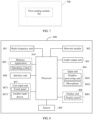
- FIG. 8 is a schematic diagram of a hardware structure of a first device implementing an embodiment of the present application.
- the first device is a terminal, or the first device is a reconfigurable intelligent surface RIS or a relay.
- the first device 800 includes, but is not limited to: a radio frequency unit 801, a network module 802, an audio output unit 803, an input unit 804, a sensor 805, a display unit 806, a user input unit 807, an interface unit 808, a memory 809, and a processor 810 and other components.
- the first device 800 may further include the power supply (for example, a battery) supplying power to each component.
- the power supply may be logically connected to the processor 810 by using a power management system, so as to implement functions such as charging management, discharging management and power consumption management by using the power management system.
- the first device structure shown in FIG. 8 does not constitute any limitation on the first device, and the first device may include more or fewer components than those shown in the figure, or combine some components, or have different component arrangements.
- the input unit 804 may include a graphics processing unit (Graphics Processing Unit, GPU) 8041 and a microphone 8042, and the graphics processing unit 8041 processes image data of a still picture or a video obtained by an image capture apparatus (such as a camera) in a video capture mode or an image capture mode.
- the display unit 806 may include a display panel 8061, and the display panel 8061 may be configured in a form of a liquid crystal display, an organic light-emitting diode, or the like.
- the user input unit 807 includes a touch panel 8071 and another input device 8072.
- the touch panel 8071 is also referred to as a touchscreen.
- the touch panel 8071 may include two parts: a touch detection apparatus and a touch controller.
- the another input device 8072 may include but is not limited to a physical keyboard, a functional button (such as a volume control button or a power on/off button), a trackball, a mouse, and a joystick. Details are not described herein.
- the radio frequency unit 801 receives downlink data from a network side device and then sends the downlink data to the processor 810 for processing; and sends uplink data to the network side device.
- the radio frequency unit 801 includes but is not limited to an antenna, at least one amplifier, a transceiver, a coupler, a low noise amplifier, a duplexer, and the like.
- the memory 809 may be configured to store a software program or an instruction and various pieces of data.
- the memory 809 may mainly include a program or instruction storage area and a data storage area.
- the program or instruction storage area may store an operating system, and an application or an instruction required by at least one function (for example, a sound playing function or an image playing function).
- the memory 809 may include a high-speed random access memory, and may further include a non-volatile memory.
- the non-volatile memory may be a read-only memory (Read-Only Memory, ROM), a programmable read-only memory (Programmable ROM, PROM), an erasable programmable read-only memory (Erasable PROM, EPROM), an electrically erasable programmable read-only memory (Electrically EPROM, EEPROM), or a flash memory, for example, at least one disk storage component, a flash memory component, or another non-volatile solid-state storage component.
- ROM Read-Only Memory
- PROM programmable read-only memory
- Erasable PROM Erasable PROM
- EPROM electrically erasable programmable read-only memory
- EEPROM electrically erasable programmable read-only memory
- flash memory for example, at least one disk storage component, a flash memory component, or another non-volatile solid-state storage component.
- the processor 810 may include one or more processing units.
- an application processor and a modem processor may be integrated into the processor 810.
- the application processor mainly processes an operating system, a user interface, an application, an instruction, or the like.
- the modem processor mainly processes wireless communication, for example, a baseband processor. It can be understood that, alternatively, the modem processor may not be integrated into the processor 810.
- the first device can implement the processes in the method embodiments in FIG. 3 , and achieve the same technical effect. To avoid duplication, details are not described herein again.
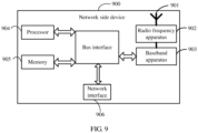
- the network side device 900 includes an antenna 901, a radio frequency apparatus 902, and a baseband apparatus 903.
- the antenna 901 is connected to the radio frequency apparatus 902.
- the radio frequency apparatus 902 receives information by using the antenna 901, and transmits the received information to the baseband apparatus 903 for processing.
- the baseband apparatus 903 processes information to be sent and transmits the information to the radio frequency apparatus 902, and the radio frequency apparatus 902 processes the received information and then transmits the information through the antenna 901.
- the foregoing band processing apparatus may be located in the baseband apparatus 903, and the method performed by the network side device in the foregoing embodiment may be implemented in the baseband apparatus 903.
- the baseband apparatus 903 includes a processor 904 and a memory 905.
- the baseband apparatus 903 may include, for example, at least one baseband board, where a plurality of chips are disposed on the baseband board. As shown in FIG. 9 , one chip is, for example, the processor 904, which is connected to the memory 905, so as to invoke a program in the memory 905 to perform operations of the network device shown in the foregoing method embodiment.
- the baseband apparatus 903 may further include a network interface 906, configured to exchange information with the radio frequency apparatus 902, where the interface is, for example, a common public radio interface (common public radio interface, CPRI for short).
- a network interface 906 configured to exchange information with the radio frequency apparatus 902, where the interface is, for example, a common public radio interface (common public radio interface, CPRI for short).
- the network side device in this embodiment of the present application further includes an instruction or a program that is stored in the memory 905 and that can be run on the processor 904.
- the processor 904 invokes the instruction or the program in the memory 905 to perform the method performed by the modules shown in FIG. 7 , and a same technical effect is achieved. To avoid repetition, details are not described herein again.
- An embodiment of the present application further provides a computer program product, the computer program product is stored in a non-volatile storage medium, and when the computer program product is executed by at least one processor, the step of the processing method according to FIG. 3 or FIG. 4 is performed.
- An embodiment of the present application further provides a readable storage medium.
- the readable storage medium stores a program or an instruction, and when the program or the instruction is executed by a processor, the various processes of the foregoing method embodiment according to FIG. 3 or FIG. 4 is performed and the same technical effects can be achieved. To avoid repetition, details are not described herein again.
- the processor is a processor in the terminal in the foregoing embodiment.
- the readable storage medium includes a computer-readable storage medium such as a read-only memory (Read-Only Memory, ROM), a random access memory (Random Access Memory, RAM), a magnetic disk, an optical disc, or the like.
- An embodiment of the present application further provides a chip, the chip includes a processor and a communication interface, the communication interface is coupled to the processor, and the processor is configured to run the program or instruction of the network side device to realize each process of the embodiment of the method according to FIG. 3 or FIG. 4 , and can achieve the same technical effect. To avoid repetition, details are not repeated herein.
- the chip mentioned in this embodiment of the present application may also be referred to as a system-level chip, a system chip, a chip system, or an on-chip system chip.
- the method in the foregoing embodiment may be implemented by software in addition to a necessary universal hardware platform or by hardware only. In most circumstances, the former is a preferred implementation. Based on such an understanding, the technical solutions of the present application essentially or the part contributing to existing technologies may be implemented in a form of a software product.
- the computer software product is stored in a storage medium (such as a ROM/RAM, a magnetic disk, or an optical disc) and includes several instructions for instructing a terminal (which may be a mobile phone, a computer, a server, an air conditioner, or a network device) to execute the methods described in the embodiments of the present application.
Landscapes
- Engineering & Computer Science (AREA)
- Signal Processing (AREA)
- Computer Networks & Wireless Communication (AREA)
- Mobile Radio Communication Systems (AREA)
Abstract
Description
- The present application claims priority to
Chinese Patent Application No. 202011233776.X, filed in November 6, 2020 - The present application belongs to the field of communication technologies, and specifically relates to a method and an apparatus for indicating a working mode of a reconfigurable intelligent surface (RIS) and a device.
- An intelligent surface device consists of a massive device array and an array control module. The massive device array is a large amount of device units that are regularly and repeatedly arranged on a planar baseboard. To achieve a considerable signal control effect, hundreds or thousands of device units are usually required to form the device array. Each device unit has a variable device structure. For example, the device unit includes a positive-intrinsic-negative (PIN) diode, and a response mode of the device unit for an external wireless signal depends on a switch state of the PIN diode. The array control module of the intelligent surface may control a working state of each device unit, to dynamically or semi-statically control a response mode of each device unit for a wireless signal. Wireless response signals of the device units of the massive device array are superposed to each other, forming a specified beam propagation feature in a macro sense. The control module is a "brain" of the intelligent surface device, and determines a wireless signal response beam of the intelligent surface according to a requirement of a communications system, so that an original static communication environment becomes "intelligent" and "controllable".
- A working mode of the RIS corresponds to the emission or transmission effect of the RIS on an incident signal, and the emission or transmission effect can be controlled by switch patterns of diodes corresponding to all units of the RIS. For example, the switch patterns of diodes corresponding to all units of each RIS correspond to a working mode of the RIS. In a same RIS working mode, if an incident wave and a reflected wave are exchanged, the reflection effect of the RIS on an incident signal is symmetrical or equivalent to some extent. For example, in a same working mode, a base station sends a signal to the RIS, and the RIS reflects the signal to the terminal. If the signal is transmitted from the UE, the base station can also receive the signal transmitted by the RIS. That is, the RIS working mode has uplink and downlink symmetry. However, the uplink and downlink symmetry of the RIS working mode affects downlink signal reception and uplink signal transmission of the same terminal. Similarly, there are similar problems in a relay working mode.
- Therefore, how to indicate the working mode of the RIS or the relay is an urgent problem to be solved.
- The purpose of the embodiments of the present application is to provide a working mode indicating method and apparatus and device, so as to indicate the working mode of the RIS or the relay.
- To resolve the foregoing technical problem, the present application is implemented as follows:
- In a first aspect, there is provided a working mode indicating method, performed by a first device, where the first device is a terminal, or the first device is an RIS node or a relay node. The method includes:
receiving first information sent by a network side device, where the first information indicates an RIS working mode or a relay working mode. - In a second aspect, there is provided a working mode indicating method, performed by a network side device, including:
sending first information, where the first information indicates an RIS working mode or a relay working mode. - In a third aspect, there is provided a working mode indicating apparatus, including:
a first receiving module, configured to receive first information, where the first information indicates an RIS working mode or a relay working mode. - In a fourth aspect, there is provided a working mode indicating apparatus, including:
a first sending module, configured to send first information, where the first information indicates an RIS working mode or a relay working mode. - In a fifth aspect, there is provided a first device. The first device is a terminal, or the first device is an RIS node or a relay node, including: a processor, a memory, and a program stored in the memory and executable on the processor, and when the program is executed by the processor, step of the method according to the first aspect is performed.
- In a sixth aspect, there is provided a network side device. The network side device includes: a processor, a memory, and a program stored in the memory and executable on the processor, and when the program is executed by the processor, step of the method according to the second aspect is performed.
- In a seventh aspect, a readable storage medium is provided. The readable storage medium stores a program or an instruction, and when the program or the instruction is executed by a processor, step of the method according to the first aspect or the second aspect is performed.
- In an eighth aspect, a computer program product is provided, the computer program product is stored in a non-volatile storage medium, and when the computer program product is executed by at least one processor, step of the method according to the first aspect or the second aspect is performed.
- In a ninth aspect, a chip is provided, the chip includes a processor and a communication interface, the communication interface is coupled to the processor, and the processor is used to run programs or instructions, so as to implement the processing method according to the first aspect or the second aspect.
- In the embodiments of the present application, the network side indicates the RIS working mode or the relay working mode, so that the uplink transmission and downlink reception of the same terminal use the same RIS working mode or the relay working mode, which solves the impact of the uplink and downlink symmetry of the RIS working mode or the relay working mode on the downlink signal reception and uplink signal transmission of the same terminal.
-
-
FIG. 1a andFIG. 1b are schematic diagrams of uplink and downlink symmetry of an RIS working mode; -
FIG. 2 is a block diagram of a wireless communications system to which an embodiment of the present application is applied; -
FIG. 3 is a first flowchart of a working mode indicating method in an embodiment of the present application; -
FIG. 4 is a second flowchart of a working mode indicating method in an embodiment of the present application; -
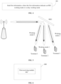
FIG. 5 is a schematic diagram of indicating an RIS working mode in an embodiment of the present application; -
FIG. 6 is a first schematic diagram of a working mode indicating apparatus in an embodiment of the present application; -
FIG. 7 is a second schematic diagram of a working mode indicating apparatus in an embodiment of the present application; -
FIG. 8 is a schematic diagram of a first device in an embodiment of the present application; and -
FIG. 9 is a schematic diagram of a network side device in an embodiment of the present application. - The following clearly describes the technical solutions in the embodiments of the present application with reference to the accompanying drawings in the embodiments of the present application. Apparently, the described embodiments are some but not all of the embodiments of the present application. All other embodiments obtained by a person of ordinary skill in the art based on the embodiments of the present application without creative efforts shall fall within the protection scope of the present application.
- The terms "first", "second", and the like in the specification and claims of the present application are used to distinguish between similar objects instead of describing a designated order or sequence. It should be understood that, data used in this way is interchangeable in proper circumstances, so that the embodiments of the present application can be implemented in an order other than the order illustrated or described herein. Objects classified by "first" and "second" are usually of a same type, and the number of objects is not limited. For example, there may be one or more first objects. In addition, "and" in the specification and claims represents at least one of connected objects. Symbol "/" generally represents an "or" relationship between associated objects.
- It should be noted that, the technologies described in the embodiments of the present application are not limited to a Long Term Evolution (Long Term Evolution, LTE)/LTE-Advanced (LTE-Advanced, LTE-A) system, and can also be used in other wireless communications systems such as Code Division Multiple Access (Code Division Multiple Access, CDMA), Time Division Multiple Access (Time Division Multiple Access, TDMA), Frequency Division Multiple Access (Frequency Division Multiple Access, FDMA), Orthogonal Frequency Division Multiple Access (Orthogonal Frequency Division Multiple Access, OFDMA), Single-carrier Frequency-Division Multiple Access (Single-carrier Frequency-Division Multiple Access, SC-FDMA), and another system. The terms "system" and "network" in the embodiments of the present application may be used interchangeably. The described technologies can be applied to both the systems and the radio technologies mentioned above as well as to other systems and radio technologies. However, a new radio (New Radio, NR) system is described in the following description for illustrative purposes, and the NR terminology is used in most of the following description, although these technologies can also be applied to applications other than the NR system application, such as the 6th generation (6th Generation, 6G) communications system.
- In order to facilitate the understanding of the embodiments of the present application, the following technical points are introduced first:
- 1. Intelligent surface/metamaterial surface
- Intelligent surfaces are an emerging technology. There are several related terms as follows, which all refer to similar technologies or entities. These terms include:
- large intelligent surface (LIS);
- intelligent reflect array (SRA);
- configurable reflect array (RRA);
- intelligent reflecting surface (IRS); and
- reconfigurable intelligent surface (RIS).
- An intelligent surface technology is applied in a plurality of technical fields. There are many different design solutions according to different application scenarios. According to the physical principle of the device unit, the intelligent surface includes tunable resonator (Tunable Resonator) variable capacitance type, guided wave (Guided Wave) waveguide type, element rotation (Element Rotation) polarization type, and the like. According to the wireless signal output form, the intelligent surface is divided into reflection Type intelligent surface and transmission type intelligent surface. According to wireless signal response parameters, the intelligent surface includes phase control intelligent surface, amplitude control intelligent surface, and amplitude phase joint control intelligent surface. According to response parameter control, the intelligent surface is divided into continuous control type and discrete control type. According to the frequency or speed of controlling the amplitude and phase of the intelligent surface, the intelligent surface can be divided into statically, semi-statically, or dynamically controlled intelligent surfaces, where static intelligent surfaces can be applied to existing systems at present, for example, the fourth generation mobile communication technology (4G)/fifth-generation mobile communication technology (5G) system. In view of complexity of design and fabrication of the devices, discrete controlled device units using single radio signal response parameters are generally chosen in the academic community for research. At present, the intelligent reflecting surface (IRS) that is widely discussed in the academic circle is a phase-controlled intelligent surface based on signal reflection. The phase change of 0 or π is realized by controlling the phase of the reflected signal of the device unit with indication information of 1 bit.
- Since radio frequency and baseband processing circuits are not required, the intelligent surface device has several advantages over a conventional wireless communication transceiver device:
- (1) Smart surface devices have lower costs and implementation complexity.
- (2) Smart surface devices have lower power consumption.
- (3) The intelligent surface will not introduce additional thermal noise at the receiving end.
- (4) Smart surface devices are thin and light, enabling flexible deployment.
- The types of RIS reflection units are as follows:
- (1) Tunable resonator: A variable capacitor is integrated into a resonator to generate a phase shift by changing a frequency of a frequency-agile patch resonator.
- (2) Guided wave control method: In this case, an arriving space wave is coupled to a guided wave by an antenna, and then the guided wave is phase-shifted and re-transmitted, forming an antenna phase shifter.
- (3) Rotation technology of circularly polarized waves: A reflection law of electromagnetic waves is used to design.
- Reflect arrays/intelligent surfaces can be classified into two types according to whether dynamic control can be performed:
- (1) Static reflective array/intelligent surface: The structure and function of the reflective array can be fixed. For an incident wave at an angle, the metasurface unit causes fixed changes in features such as the amplitude, phase, and polarization of the incident wave, to obtain the corresponding reflected wave.
- (2) Dynamic reflective array/intelligent surface: The structure and function of the reflective array can be controlled. For an incident wave at an angle, features such as the amplitude, phase, and polarization of the incident wave can be controlled to change differently by programming, to obtain the corresponding reflected wave. To achieve programmable control of reflective metasurfaces, switch elements (such as diodes) need to be introduced into reflective units. The PIN diode is currently a common option for controlling a reconfigurable hypersurface. The PIN diode has a relatively wide range of radio frequency impedance and low distortion, and is widely used in the microwave radio frequency field. The switch element in the reflection unit has a plurality of different states, and switching of different states can be implemented by controlling on/off of the switch element. In on and off cases of the switch element, a structure and performance of the corresponding reflection unit changes greatly. That is, reflection units in different states have different regulation modes for characteristics such as an amplitude, a phase, and polarization of the incident wave.
- Since the intelligent surface includes a large number of device units and has no radio frequency and baseband processing capabilities, this type of intelligent surface is called a passive intelligent surface.
- Since the intelligent surface is composed of a large amount of component units and does not have a radio frequency and baseband processing capability, the base station cannot separately obtain channel information from the base station to the intelligent surface and from the intelligent surface to the terminal. A receive signal of the base station or the terminal is formed by superimposing response signals of a large amount of component units of the intelligent surface, and changing a working state of one component unit or a small amount of component units does not cause a significant change of the receive signal. A possible measurement scheme is to install a small amount of active component units in the intelligent surface, so that the intelligent surface can perform channel measurement and feedback. The base station calculates a reasonable intelligent surface configuration parameter from limited channel information by using a compression sensing or deep learning algorithm. An intelligent surface-based communications system needs an efficient channel measurement mechanism, to improve end-to-end signal quality as much as possible while ensuring low complexity of the intelligent surface. This intelligent surface on which some active components are installed has a capability of receiving and even sending a signal, and is an active and passive intelligent surface (or an active intelligent surface).
- A working mode of the RIS corresponds to the emission or transmission effect of the RIS on an incident signal, and the emission or transmission effect can be controlled by switch patterns of diodes corresponding to all units of the RIS. For example, the switch patterns of diodes corresponding to all units of each RIS correspond to a working mode of the RIS.
- Generally, an RIS can only work in one mode at a time.
- In a same working mode, as shown in
FIG. 1a andFIG. 1b , a base station sends a signal to an RIS, and the RIS reflects the signal to a terminal. At this time, the RIS works in workingmode 1. - Similarly, in the
RIS working mode 1, if the signal is transmitted from the terminal, the base station can also receive the signal transmitted through the RIS. - That is, in the same RIS working mode, if the incident wave and the reflected wave are exchanged, the reflection effect of the RIS on the incident signal is symmetrical or equivalent to some extent.
- The fifth-generation mobile communication technology (5G) allocates uplink and downlink resource ratios in units of slots (Slots) or even orthogonal frequency division multiplex (OFDM) symbols.
- The communication system supports the use of cell-specific (Cell specific) and terminal-specific (UE specific) radio resource control (Radio Resource Control, RRC) signaling to indicate uplink and downlink subframe ratios of UEs.
- The communication system supports flexible adjustment of uplink and downlink resource ratios through downlink control information (DCI) signaling, and 55 standardized structures are predefined (a maximum of 254 structures are reserved).
- As shown in Table 1: Taking 14 symbols as an example, D means that the symbol is a downlink symbol, U means that the symbol is an uplink symbol, and F means that the symbol is a flexible symbol (that is, it is not sure whether it is an uplink or downlink symbol).
Table 1 Format Number of symbols in a slot #DL #UL #Flex 0 1 2 3 4 5 6 7 8 9 10 11 12 13 0 D D D D D D D D D D D D D D 14 0 0 1 U U U U U U U U U U U U U U 0 14 0 2 F F F F F F F F F F F F F F 0 0 14 3 D D D D D D D D D D D D D F 13 0 1 4 D D D D D D D D D D D D F F 12 0 2 5 D D D D D D D D D D D F F F 11 0 3 6 D D D D D D D D D D F F F F 10 0 4 7 D D D D D D D D D F F F F F 9 0 5 8 F F F F F F F F F F F F F U 0 1 13 9 F F F F F F F F F F F F U U 0 2 12 10 F U U U U U U U U U U U U U 0 13 1 11 F F U U U U U U U U U U U U 0 12 2 12 F F F U U U U U U U U U U U 0 11 3 13 F F F F U U U U U U U U U U 0 10 4 14 F F F F F U U U U U U U U U 0 9 5 15 F F F F F F U U U U U U U U 0 8 6 16 D F F F F F F F F F F F F F 1 0 13 17 D D F F F F F F F F F F F F 2 0 12 18 D D D F F F F F F F F F F F 3 0 11 19 D F F F F F F F F F F F F U 1 1 12 20 D D F F F F F F F F F F F U 2 1 11 21 D D D F F F F F F F F F F U 3 1 10 22 D F F F F F F F F F F F U U 1 2 11 23 D D F F F F F F F F F F U U 2 2 10 24 D D D F F F F F F F F F U U 3 2 9 25 D F F F F F F F F F F U U U 1 3 10 26 D D F F F F F F F F F U U U 2 3 9 - Referring to
FIG. 2, FIG. 2 is a block diagram of a wireless communications system to which embodiments of the present application can be applied. The wireless communication system includes a terminal 21, a network side device 22, and anintelligent surface device 23. The terminal 21 may also be called a terminal device or user equipment (UE), and the terminal 21 may be a mobile phone, a tablet personal computer (Tablet Personal Computer), a laptop computer (Laptop Computer) or a notebook computer, a personal digital Assistant (PDA), a palmtop computer, a netbook, an ultra-mobile personal computer (UMPC), a mobile Internet device (MID), a wearable device (Wearable Device) or a vehicle-mounted device (VUE), a pedestrian terminal (PUE), and other terminal side devices. The wearable device includes: bracelets, earphones, glasses, etc. It should be noted that a specific type of the terminal 21 is not limited in the embodiments of the present application. - The network side device 22 may be a base station or a core network. The base station may be referred to as a node B, an evolved node B, an access point, a base transceiver station (BTS), a radio base station, a radio transceiver, a basic service set (BSS), an extended service set (ESS), a node B, an evolved node B (eNB), a home node B, a home evolved node B, a wireless local area network (WLAN) access point, a wireless fidelity (WiFi) node, a transmitting receiving point (TRP), a wireless access network node, or other appropriate terms in the art. As long as a same technical effect is achieved, the base station is not limited to a specified technical term. It should be noted that, in embodiments of the present application, only a base station in the NR system is used as an example, but a specific type of the base station is not limited.
- With reference to the accompanying drawings, the following describes in detail a working mode indicating method and apparatus, a device, and a readable storage medium in the embodiments of the present application based on specific embodiments and application scenarios.
- Referring to
FIG. 3 , an embodiment of the present application provides a working mode indicating method, executed by a first device. The first device is a terminal, or the first device is an RIS node or a relay node, for example, alayer 1 relay, alayer 2 relay, alayer 3 relay, or an integrated access and backhaul (IAB) node. The method includes:step 301. - Step 301: Receive first information sent by a network side device, where the first information indicates an RIS working mode or a relay working mode.
- Optionally, the first information may also be radio resource control (RRC) signaling; or the first time unit may be each time unit in a specific period, and the time unit may be a slot (slot) or a symbol (symbol) or other time granularity.
- In this embodiment of the application, the RIS working mode or the relay working mode is associated with at least one of the following:
- (1) beam pointing of a reflected signal or a refracted signal of an RIS, or beam pointing of a reflected signal or a refracted signal of a relay; for example, different working modes correspond to different beam pointing of the reflected signal, or different working modes correspond to different beam pointing of the refracted signal;
- (2) a beamforming mode of a reflected signal or a refracted signal of an RIS, or a beamforming mode of a reflected signal or a refracted signal of a relay; for example, the beamforming mode of the RIS is obtained by adjusting on or off of a diode associated with the RIS unit, that is, different on or off patterns of different diodes correspond to different beamforming modes of the reflected signal or the refracted signal of the RIS, thus corresponding to different RIS working modes;
- (3) a polarization manner of a reflected signal or a refracted signal of an RIS, or a polarization manner of a reflected signal or a refracted signal of a relay, and the polarization mode includes: horizontal polarization or vertical polarization; for example, different working modes correspond to different polarization modes; and
- (4) an orbital angular momentum (OAM) mode of a reflected signal or a refracted signal of an RIS, or an orbital angular momentum (OAM) mode of a reflected signal or a refracted signal of a relay; for example, different working modes correspond to different OAM modes.
- In this embodiment of the present application, the RIS working mode or the relay working mode is quasi co-located (QCL) with at least one of the following:
- (1) a synchronization signal and pbch block (SSB) sent by the network side device;
- (2) a channel state information reference signal (CSI-RS) sent by the network side device;
- (3) a tracking reference signal (TRS) sent by the network side device;
- (4) a demodulation reference signal (DMRS) sent by the network side device; and
- (5) a positioning reference signal (PRS) sent by the network side device.
- In this embodiment of the present application, the first information further indicates an uplink configuration or a downlink configuration corresponding to the RIS working mode or the relay working mode. That is, the first information may simultaneously indicate the RIS working mode and uplink/downlink configuration of each time unit, for example, time division duplex uplink downlink configuration (tdd-UL-DL-Configuration). The uplink configuration or downlink configuration includes different configurations in Table 1.
- In this embodiment of the present application, the first information is cell-specific signaling or terminal-specific signaling.
- In this embodiment of the present application, types of the RIS working mode include: a definite working mode and a flexible working mode.
- In this embodiment of the present application, the method further includes:
if the first information indicates that the type of the RIS working mode or the relay working mode is a flexible working mode, receiving second information, where the second information indicates that the RIS working mode or the relay working mode is a first working mode among definite working modes, that is, the second information may further indicate which definite working mode is the uncertain working mode. Optionally, the second information islayer 1 signaling. - Optionally, the RIS working mode or the relay working mode is the RIS working mode or the relay working mode in at least a part of time units within one period or multiple periods.
- The uplink and downlink symmetry of the RIS working mode affects the downlink signal reception and uplink signal transmission of the same UE, because the working mode of the RIS at a moment of downlink signal reception and uplink signal transmission of the same UE needs to be the same. In the embodiments of the present application, the following steps are performed:
if the RIS working mode or the relay working mode is the RIS working mode or the relay working mode on at least a part of time units within one period, a number of time units with a same RIS working mode or a same relay working mode within the one period is greater than 1; and if the RIS working mode or the relay working mode is the RIS working mode or the relay working mode on at least a part of time units within multiple periods, a number of time units with a same RIS working mode or a same relay working mode within each of the multiple periods is greater than 1. - In this embodiment of the present application, the first device is an RIS node or a relay node, and the method further includes: updating a working mode according to the first information.
- In this embodiment of the present application, the first device is a terminal, and the method further includes: performing corresponding transmission according to the RIS working mode or the relay working mode indicated by the first information.
- In this embodiment of the present application, the performing corresponding transmission according to the RIS working mode or the relay working mode indicated by the first information includes one of the following:
- performing a two-step random access process or a four-step random access process according to the RIS working mode or the relay working mode indicated by the first information;
- performing uplink data transmission or downlink data transmission according to the RIS working mode or the relay working mode indicated by the first information; and
- performing a hybrid automatic repeat request (HARQ) process according to the RIS working mode or the relay working mode indicated by the first information.
- In this embodiment of the present application, the performing a four-step random access process according to the RIS working mode or the relay working mode indicated by the first information includes:
determining the index of the target SSB; sending MSG1 at a first moment, where an RIS working mode or a relay working mode at the first moment is the same as an RIS working mode or a relay working mode corresponding to a moment of the target SSB, and the first moment corresponds to a random access occasion associated with the index of the target SSB; and listen to message 2 (MSG2) at a second moment after the terminal sends message 1 (MSG1); where an RIS working mode or a relay working mode at the second moment is the same as an RIS working mode or a relay working mode corresponding to a moment ofMSG 1. - In this embodiment of the present application, the method further includes: sending message 3 (MSG3) at a third moment after the terminal listens to the
message 2; where an RIS working mode or a relay working mode at the third moment is the same as an RIS working mode or a relay working mode corresponding to a moment of themessage 2; and
receiving a message 4 (MSG4) at a fourth moment after the terminal sends MSG3; where an RIS working mode or a relay working mode at the fourth moment is the same as an RIS working mode or a relay working mode corresponding to a moment of MSG3. - In this embodiment of the present application, the performing a two-step random access process according to the RIS working mode or the relay working mode indicated by the first information includes:
determining the index of the target SSB; sending a preamble of message A (MSGA) at a fifth moment, where an RIS working mode or a relay working mode at the fifth moment is the same as an RIS working mode or a relay working mode corresponding to a moment of the target SSB, and the fifth moment corresponds to a random access occasion associated with the index of the target SSB; sending MSGA at a sixth moment, where an RIS working mode or a relay working mode at the sixth moment is the same as an RIS working mode or a relay working mode corresponding to a moment of the target SSB; and listening to message B (MSGB) at a seventh moment after MSGA is sent, where an RIS working mode or a relay working mode at the seventh moment is the same as an RIS working mode or a relay working mode corresponding to a moment of MSGA. - In this embodiment of the present application, the performing uplink data transmission or downlink data transmission according to the RIS working mode indicated by the first information includes:
receiving fourth information; determining the index of the target SSB; and receiving downlink data or sending uplink data at an eighth moment, where the eighth moment belongs to a time resource that is used for receiving downlink data or sending uplink data and that is indicated by the fourth information, and an RIS working mode or a relay working mode at the eighth moment is the same as an RIS working mode or a relay working mode at a moment of the index of the target SSB. - In this embodiment of the present application, the performing the HARQ process according to the RIS working mode or the relay working mode indicated by the first information includes:
sending, at a ninth moment, an acknowledgment (ACK) or a negative acknowledgment (NACK) corresponding to a first channel, where an RIS working mode or a relay working mode at the ninth moment is the same as an RIS working mode or a relay working mode at a moment when the first channel is transmitted; where the first channel is a physical downlink control channel (PDCCH)/a physical downlink shared channel (PDSCH). - Optionally, the ninth moment is selected independently, or is determined based on network side configuration.
- In the embodiments of the present application, the network side indicates the RIS working mode or the relay working mode, so that the uplink transmission and downlink reception of the same terminal use the same RIS working mode or the relay working mode, which solves the impact of the uplink and downlink symmetry of the RIS working mode or the relay working mode on the downlink signal reception and uplink signal transmission of the same terminal.
- Referring to
FIG. 4 , an embodiment of the present application provides a working mode indicating method, executed by a network side device, and the specific steps include:step 401. - Step 401: Send first information, where the first information indicates an RIS working mode or a relay working mode.
- For example, the first information is sent to the terminal, or the first information is sent to the RIS or the relay.
- In this embodiment of the application, the RIS working mode or the relay working mode is associated with at least one of the following: (1) beam pointing of a reflected signal or a refracted signal of an RIS, or beam pointing of a reflected signal or a refracted signal of a relay; (2) a beamforming mode of a reflected signal or a refracted signal of an RIS, or a beamforming mode of a reflected signal or a refracted signal of a relay; (3) a polarization manner of a reflected signal or a refracted signal of an RIS, or a polarization manner of a reflected signal or a refracted signal of a relay; and (4) an OAM manner of a reflected signal or a refracted signal of an RIS, or an OAM manner of a reflected signal or a refracted signal of a relay.
- In this embodiment of the application, the RIS working mode or the relay working mode is quasi-co-located with at least one of the following: (1) an SSB sent by the network side device, (2) a CSI-RS sent by the network side device, (3) a TRS sent by the network-side device, (4) a DMRS sent by the network-side device and (5) a PRS that are sent by the network-side device.
- In this embodiment of the present application, the first information further indicates an uplink configuration or a downlink configuration corresponding to the RIS working mode or the relay working mode.
- In this embodiment of the present application, the first information is cell-specific signaling or terminal-specific signaling.
- In this embodiment of the present application, types of the RIS working mode or the relay working mode include: a definite working mode and a flexible working mode.
- In this embodiment of the present application, the method further includes: if the first information indicates that the type of the RIS working mode or the relay working mode is a flexible working mode, sending second information, where the second information indicates that the RIS working mode or the relay working mode is a first working mode among uncertain working modes. Optionally, the second information is
layer 1 signaling. - In this embodiment of the present application, the RIS working mode or the relay working mode is the RIS working mode or the relay working mode in at least a part of time units within one period or multiple periods.
- In the embodiments of the present application, the network side indicates the RIS working mode or the relay working mode, so that the uplink transmission and downlink reception of the same terminal use the same RIS working mode or the relay working mode, which solves the impact of the uplink and downlink symmetry of the RIS working mode or the relay working mode on the downlink signal reception and uplink signal transmission of the same terminal.
- The following uses four manners to introduce the manner of indicating the RIS working mode:
- Indicate the RIS working mode through base station SIB (cell specific) or RRC signaling (UE specific). The RIS working mode at each moment is determinate. The RRC signaling (UE specific) may replace the uncertain working mode indicated by the SIB (cell specific) signaling, for example, indicating that the uncertain working mode is working
mode 1. - Optionally, the tdd-UL-DL-Configuration is indicated through additional signaling.
- As shown in Table 2: the RIS working mode can be indicated through SIB or RRC signaling.
Table 2 Slot or symbol index 0 1 2 3 4 5 6 7 8 9 RIS working mode 0 1 2 1 2 0 1 2 0 0 - For example, SIB or RRC signaling indicates: the RIS working mode of the slot or symbol with
index 0 is workingmode 0, and the RIS working mode of the slot or symbol withindex 1 is workingmode 1, the RIS working mode of the slot or symbol withindex 2 is workingmode 2, and the RIS working mode of the slot or symbol withindex 3 is a workingmode 1, and the RIS working mode of the slot or symbol with index 4 is a workingmode 2, the RIS working mode of the slot or symbol with index 5 is workingmode 0, and the RIS working mode of the slot or symbol with index 6 is workingmode 1, the RIS working mode of the slot or symbol with index 7 is workingmode 2, and the RIS working mode of the slot or symbol with index 8 is a workingmode 0, and the RIS working mode of the slot or symbol with index 9 is a workingmode 0. - Referring to
FIG. 6 , SIB or RRC signaling indicates that the RIS working mode ofterminal 1 is workingmode 0, indicates that the RIS working mode ofterminal 2 is workingmode 1, and indicates that the RIS working mode ofterminal 3 is workingmode 2. - Indicate the RIS working mode through base station SIB (cell specific) or RRC signaling (UE specific). The RIS working modes of some time units are uncertain. The RRC signaling (UE specific) may replace the uncertain working mode indicated by the SIB (cell specific) signaling, for example, indicating that the uncertain working mode is working
mode 1. - Then, the
layer 1 signaling indicates which working mode the uncertain working mode is. - Optionally, the tdd-UL-DL-Configuration is indicated through additional signaling.
- As shown in Table 3: RIS working modes that can be indicated through SIB or RRC signaling (indicate which working mode is the pending/flexible working mode through
layer 1 signaling).Table 3 Slot or symbol index 0 1 2 3 4 5 6 7 8 9 RIS working mode 0 1 2 F F 0 1 2 F F - F represents an uncertain RIS working mode, or an uncertain/pending/flexible working mode.
- For example, SIB or RRC signaling indicates: the RIS working mode of the slot or symbol with
index 0 is workingmode 0, and the RIS working mode of the slot or symbol withindex 1 is workingmode 1, the RIS working mode of the slot or symbol withindex 2 is workingmode 2, and the RIS working mode of the slot or symbol withindex 3 is an uncertain working mode, and the RIS working mode of the slot or symbol with index 4 is an uncertain working mode, the RIS working mode of the slot or symbol with index 5 is workingmode 0, and the RIS working mode of the slot or symbol with index 6 is workingmode 1, the RIS working mode of the slot or symbol with index 7 is workingmode 2, and the RIS working mode of the slot or symbol with index 8 is an uncertain working mode, and the RIS working mode of the slot or symbol with index 9 is an uncertain working mode. - Indicate the RIS working mode and tdd-UL-DL-Configuration at the same time through the base station SIB (cell specific) or RRC signaling (UE specific).
- The RRC signaling (UE specific) may replace the uncertain working mode indicated by the SIB (cell specific) signaling, for example, indicating that the uncertain working mode is working
mode 1. - The RIS working mode of each time unit is determinate.
- As shown in Table 4: RIS working modes that can be indicated through SIB or RRC signaling (indicate which working mode is the pending/flexible working mode through
layer 1 signaling).Table 4 Slot or symbol index 0 1 2 3 4 5 6 7 8 9 DL/UL D D S U U D S U F F RIS working mode 0 1 2 1 2 0 1 2 0 0 - For example, SIB or RRC signaling indicates: the RIS working mode of the slot or symbol with index 0 is working mode 0, the slot or symbol is a downlink slot or symbol, and the RIS working mode of the slot or symbol with index 1 is working mode 1, the slot or symbol is a downlink slot or symbol, the RIS working mode of the slot or symbol with index 2 is working mode 2, the slot or symbol is a special slot or special symbol, and the RIS working mode of the slot or symbol with index 3 is an uncertain working mode, and the slot or symbol is an uplink slot or symbol, and the RIS working mode of the slot or symbol with index 4 is an uncertain working mode, and the slot or symbol is an uplink slot or symbol, the RIS working mode of the slot or symbol with index 5 is working mode 0, the slot or symbol is a downlink slot or symbol, and the RIS working mode of the slot or symbol with index 6 is working mode 1, the slot or symbol is S, the RIS working mode of the slot or symbol with index 7 is working mode 2, the slot or symbol is an uplink slot or symbol, and the RIS working mode of the slot or symbol with index 8 is an uncertain working mode, the slot or symbol is a flexible slot or symbol, and the RIS working mode of the slot or symbol with index 9 is an uncertain working mode, and the slot or symbol is a flexible slot or symbol. The DL/UL in
manner 3 can be different configurations in Table 1. - Indicate the RIS working mode and tdd-UL-DL-Configuration simultaneously through the base station SIB (cell specific) or RRC signaling (UE specific). Among them, RRC signaling (UE specific) can replace the uncertain working mode indicated by SIB (cell specific) signaling, for example, indicating that the uncertain working mode is working
mode 1. - The RIS working modes of some time units are uncertain.
- Further, the
layer 1 signaling indicates which working mode the uncertain RIS working mode is. - As shown in Table 5,
layer 1 signaling can simultaneously indicate which working mode the uncertain RIS working mode is, and which symbol/slot (uplink or downlink) the uncertain uplink and downlink symbols/slots are.Table 5 Slot or symbol index 0 1 2 3 4 5 6 7 8 9 DL/UL D D S U U D S U F F RIS working mode 0 1 2 F F 0 1 2 F F - For example, SIB or RRC signaling indicates: the RIS working mode of the slot or symbol with index 0 is working mode 0, the slot or symbol is a downlink slot or symbol, and the RIS working mode of the slot or symbol with index 1 is working mode 1, the slot or symbol is a downlink slot or symbol, the RIS working mode of the slot or symbol with index 2 is working mode 2, the slot or symbol is a special slot or special symbol, and the RIS working mode of the slot or symbol with index 3 is an uncertain working mode, and the slot or symbol is an uplink slot or symbol, and the RIS working mode of the slot or symbol with index 4 is an uncertain working mode, and the slot or symbol is an uplink slot or symbol, the RIS working mode of the slot or symbol with index 5 is working mode 0, the slot or symbol is a downlink slot or symbol, and the RIS working mode of the slot or symbol with index 6 is working mode 1, the slot or symbol is a special slot or special symbol, the RIS working mode of the slot or symbol with index 7 is working mode 2, the slot or symbol is an uplink slot or symbol, and the RIS working mode of the slot or symbol with index 8 is an uncertain working mode, the slot or symbol is a flexible slot or symbol, and the RIS working mode of the slot or symbol with index 9 is an uncertain working mode, and the slot or symbol is a flexible slot or symbol. The DL/UL in manner 4 can be different configurations in Table 1.
- Four application scenarios of the RIS working mode indicating method are introduced below in conjunction with
Embodiment 1 to Embodiment 4. - After measuring and determining the index of the target SSB (for example, selecting an SSB whose reference signal received power (RSRP) meets a threshold as the index of the target SSB), at a random access occasion (RO) associated with the SSB, and at a time unit in which the RIS working mode is the same as the RIS working mode corresponding to the SSB index, MSG1 is sent. Alternatively, after the UE determines
- that the UE sends MSG1, in the first time window, at a time unit in which the RIS working mode is the same as the RIS working mode corresponding to MSG1, MSG2 is listened to, and
- after the UE listens to MSG2, it sends MSG3 at the time unit indicated by MSG2.
- Optionally, the RIS working mode corresponding to the time unit is the same as the RIS working mode corresponding to MSG2.
- After the UE sends MSG3, in the second time window, at a time unit in which the RIS working mode is the same as the RIS working mode corresponding to MSG3, MSG4 is received.
- The UE determines, according to one of the above four indication manners, the RIS working mode corresponding to each time unit.
- After measuring and determining the index of the target SSB (for example, selecting the SSB whose RSRP meets a certain threshold as the index of the target SSB), at the RO associated with the SSB, at a time unit in which the RIS working mode is the same as the RIS working mode corresponding to the SSB index, the preamble of MSGA is sent.
- The UE sends a physical uplink shared channel (PUSCH) of MSGA in a time unit in which the RIS working mode is the same as the RIS working mode corresponding to the SSB index.
- After the UE sends MSGA, in the third time window, at a time unit in which the RIS working mode is the same as the RIS working mode corresponding to MSGA, MSGB is listened to.
- The UE determines, according to one of the above four indication manners, the RIS working mode corresponding to each time unit.
- The UE receives base station signaling, such as RRC signaling or layer 1 (L1) signaling.
- The RRC signaling or L1 signaling a time-frequency resource used by the UE to receive downlink data/send uplink data at multiple moments, modulation and coding scheme (MCS) and other information.
- The UE (periodically) measures and determines the index of the target SSB (for example, selects the SSB whose RSRP meets a certain threshold as the index of the target SSB).
- According to the time resource (the first condition) for receiving downlink data/sending uplink data indicated by RRC signaling or L1 signaling, the UE receives downlink data/send uplink data at a moment at which the RIS working mode is the same as the RIS working mode corresponding to a moment of the target SSB index (the second condition).
- Embodiment 4: PDSCH and corresponding acknowledgment (ACK)/negative acknowledgment (NACK).
- On the basis that the UE determines the ACK/NACK transmission time according to the existing technology, it also needs to be satisfied that the RIS working mode at the ACK/NACK transmission time is the same as the RIS working mode at a moment of the associated physical downlink control channel (PDCCH)/physical downlink shared channel (PDSCH).
- Specifically, the UE may autonomously select the ACK/NACK transmission time that meets the conditions, or the base station indicates, for example, through the PDCCH, the ACK/NACK transmission time that meets the condition.
- It can be understood that the RIS in the above embodiment can also be a relay (relay), such as
layer 1 relay,layer 2 relay,layer 3 relay, or an integrated access and backhaul (IAB) node. - Referring to
FIG. 6 , an embodiment of the present application provides a working mode indicating apparatus, and theapparatus 600 includes:
afirst receiving module 601, configured to receive first information sent by a network side device, where the first information indicates an RIS working mode or a relay working mode. - In this embodiment of the present application, the
apparatus 600 further includes:
an update module, configured to update the working mode according to the first information. - In this embodiment of the present application, the
apparatus 600 further includes:
an executing module, configured to perform corresponding transmission according to the RIS working mode or the relay working mode indicated by the first information. - In this embodiment of the application, the RIS working mode or the relay working mode is associated with at least one of the following:
- (1) beam pointing of a reflected signal or a refracted signal of an RIS, or beam pointing of a reflected signal or a refracted signal of a relay;
- (2) a beamforming mode of a reflected signal or a refracted signal of an RIS, or a beamforming mode of a reflected signal or a refracted signal of a relay;
- (3) a polarization manner of a reflected signal or a refracted signal of an RIS, or a polarization manner of a reflected signal or a refracted signal of a relay; and
- (4) an OAM manner of a reflected signal or a refracted signal of an RIS, or an OAM manner of a reflected signal or a refracted signal of a relay.
- In this embodiment of the present application, the RIS working mode or the relay working mode is quasi-co-located with at least one of the following: an SSB sent by the network side device, a CSI-RS sent by the network side device, a TRS sent by the network side device, a DMRS sent by the network side device, and a PRS sent by the network side device.
- In this embodiment of the present application, the first information further indicates an uplink configuration or a downlink configuration corresponding to the RIS working mode or the relay working mode.
- In this embodiment of the present application, the first information is cell-specific signaling or terminal-specific signaling.
- In this embodiment of the present application, types of the RIS working mode or the relay working mode include: a definite working mode and a flexible working mode.
- In the embodiment of the present application, the apparatus further includes:
a second receiving module, configured to: if the first information indicates that the type of the RIS working mode or the relay working mode is a flexible working mode, receive second information, where the second information indicates that the RIS working mode or the relay working mode is a first working mode among definite working modes. - In this embodiment of the present application, the second information is
layer 1 signaling. - In this embodiment of the present application, the RIS working mode or the relay working mode is the RIS working mode or the relay working mode in at least a part of time units within one period or multiple periods.
- In this embodiment of the present application, if the RIS working mode or the relay working mode is the RIS working mode or the relay working mode on at least a part of time units within one period, a number of time units with a same RIS working mode or a same relay working mode within the one period is greater than 1; and if the RIS working mode or the relay working mode is the RIS working mode or the relay working mode on at least a part of time units within multiple periods, a number of time units with a same RIS working mode or a same relay working mode within each of the multiple periods is greater than 1.
- In this embodiment of the present application, the executing module is further configured to: performing a two-step random access process or a four-step random access process according to the RIS working mode or the relay working mode indicated by the first information; performing uplink data transmission or downlink data transmission according to the RIS working mode or the relay working mode indicated by the first information; and performing a hybrid automatic repeat request (HARQ) process according to the RIS working mode or the relay working mode indicated by the first information.
- In this embodiment of the present application, the executing module includes:
- a determining unit, configured to determine an index of a target SSB;
- a first sending unit, configured to send
message 1 at a first moment, where an RIS working mode or a relay working mode at the first moment is the same as an RIS working mode or a relay working mode corresponding to a moment of the target SSB, and the first moment corresponds to a random access occasion associated with the index of the target SSB; and - a first monitoring unit, configured to listen to
message 2 at a second moment after the terminal sendsmessage 1; - where an RIS working mode or a relay working mode at the second moment is the same as an RIS working mode or a relay working mode corresponding to a moment of the
message 1. - In this embodiment of the present application, the executing module further includes:
- a second sending unit, configured to send
message 3 at a third moment after the terminal listens to themessage 2; where an RIS working mode or a relay working mode at the third moment is the same as an RIS working mode or a relay working mode corresponding to a moment of themessage 2; and - a first receiving unit, configured to receive MSG4 at a fourth moment after the terminal sends MSG3;
- where an RIS working mode or a relay working mode at the fourth moment is the same as an RIS working mode or a relay working mode corresponding to a moment of MSG3.
- In this embodiment of the present application, the executing module includes:
- a second determination unit, configured to determine the index of the target SSB;
- a third sending unit, configured to send a preamble of MSGA at a fifth moment, where an RIS working mode or a relay working mode at the fifth moment is the same as an RIS working mode or a relay working mode corresponding to a moment of the target SSB, and the fifth moment corresponds to a random access occasion associated with the index of the target SSB;
- a third sending unit, configured to send MSGA at a sixth moment, where an RIS working mode or a relay working mode at the sixth moment is the same as an RIS working mode or a relay working mode corresponding to a moment of the target SSB; and
- a second monitoring unit, configured to listen to MSGB at a seventh moment after MSGA is sent, where an RIS working mode or a relay working mode at the seventh moment is the same as an RIS working mode or a relay working mode corresponding to a moment of MSGA.
- In this embodiment of the present application, the executing module includes:
- a second receiving unit, configured to receive fourth information;
- a third determining unit, configured to determine an index of a target SSB; and
- a transceiver unit, configured to receive downlink data or send uplink data at an eighth moment, where the eighth moment belongs to a time resource that is used for receiving downlink data or sending uplink data and that is indicated by the fourth information, and an RIS working mode or a relay working mode at the eighth moment is the same as an RIS working mode or a relay working mode at a moment of the index of the target SSB.
- In this embodiment of the present application, the executing module is further configured to: send, at a ninth moment, a positive acknowledgment or a negative acknowledgment corresponding to a first channel, where an RIS working mode or a relay working mode at the ninth moment is the same as an RIS working mode or a relay working mode at a moment when the first channel is transmitted; where the first channel is a physical downlink control channel or a physical downlink shared channel.
- In this embodiment of the present application, the ninth moment is selected independently, or determined based on network side configuration.
- The apparatus according to an embodiments of the present disclosure can implement the processes in the method embodiments in
FIG. 3 , and achieve the same technical effect. To avoid repetition, details are not described herein again. - Referring to
FIG. 7 , an embodiment of the present application provides a working mode indicating apparatus, and theapparatus 700 includes:
afirst sending module 701, configured to send first information, where the first information indicates an RIS working mode or a relay working mode. - In this embodiment of the present application, the RIS working mode or the relay working mode is associated with at least one of the following:
- beam pointing of a reflected signal or a refracted signal of an RIS, or beam pointing of a reflected signal or a refracted signal of a relay;
- a beamforming mode of a reflected signal or a refracted signal of an RIS, or a beamforming mode of a reflected signal or a refracted signal of a relay;
- a polarization manner of a reflected signal or a refracted signal of an RIS, or a polarization manner of a reflected signal or a refracted signal of a relay; and
- an OAM manner of a reflected signal or a refracted signal of an RIS, or an OAM manner of a reflected signal or a refracted signal of a relay.
- In this embodiment of the present application, the RIS working mode or the relay working mode is quasi-co-located with at least one of the following: an SSB sent by the network side device, a CSI-RS sent by the network side device, a TRS sent by the network side device, a DMRS sent by the network side device, and a PRS sent by the network side device.
- In this embodiment of the present application, the first information further indicates an uplink configuration or a downlink configuration corresponding to the RIS working mode or the relay working mode.
- In this embodiment of the present application, the first information is cell-specific signaling or terminal-specific signaling.
- In this embodiment of the present application, types of the RIS working mode or the relay working mode include: a definite working mode and a flexible working mode.
- In the embodiment of the present application, the apparatus further includes:
a second sending module, configured to: if the first information indicates that the type of the RIS working mode or the relay working mode is an uncertain working mode, send second information, where the second information indicates that the RIS working mode or the relay working mode is a first working mode among definite working modes. - In this embodiment of the present application, the second information is
layer 1 signaling. - In this embodiment of the present application, the RIS working mode or the relay working mode is the RIS working mode or the relay working mode in at least a part of time units within one period or multiple periods.
- The apparatus according to an embodiments of the present disclosure can implement the processes in the method embodiments in
FIG. 4 , and achieve the same technical effect. To avoid repetition, details are not described herein again. -
FIG. 8 is a schematic diagram of a hardware structure of a first device implementing an embodiment of the present application. The first device is a terminal, or the first device is a reconfigurable intelligent surface RIS or a relay. - The
first device 800 includes, but is not limited to: aradio frequency unit 801, anetwork module 802, anaudio output unit 803, aninput unit 804, asensor 805, a display unit 806, auser input unit 807, aninterface unit 808, amemory 809, and aprocessor 810 and other components. - Those skilled in the art can understand that the
first device 800 may further include the power supply (for example, a battery) supplying power to each component. Preferably, the power supply may be logically connected to theprocessor 810 by using a power management system, so as to implement functions such as charging management, discharging management and power consumption management by using the power management system. The first device structure shown inFIG. 8 does not constitute any limitation on the first device, and the first device may include more or fewer components than those shown in the figure, or combine some components, or have different component arrangements. - It should be understood that, in this embodiment of the present application, the
input unit 804 may include a graphics processing unit (Graphics Processing Unit, GPU) 8041 and a microphone 8042, and thegraphics processing unit 8041 processes image data of a still picture or a video obtained by an image capture apparatus (such as a camera) in a video capture mode or an image capture mode. The display unit 806 may include a display panel 8061, and the display panel 8061 may be configured in a form of a liquid crystal display, an organic light-emitting diode, or the like. Theuser input unit 807 includes atouch panel 8071 and anotherinput device 8072. Thetouch panel 8071 is also referred to as a touchscreen. Thetouch panel 8071 may include two parts: a touch detection apparatus and a touch controller. The anotherinput device 8072 may include but is not limited to a physical keyboard, a functional button (such as a volume control button or a power on/off button), a trackball, a mouse, and a joystick. Details are not described herein. - In this embodiment of the present application, the
radio frequency unit 801 receives downlink data from a network side device and then sends the downlink data to theprocessor 810 for processing; and sends uplink data to the network side device. Usually, theradio frequency unit 801 includes but is not limited to an antenna, at least one amplifier, a transceiver, a coupler, a low noise amplifier, a duplexer, and the like. - The
memory 809 may be configured to store a software program or an instruction and various pieces of data. Thememory 809 may mainly include a program or instruction storage area and a data storage area. The program or instruction storage area may store an operating system, and an application or an instruction required by at least one function (for example, a sound playing function or an image playing function). In addition, thememory 809 may include a high-speed random access memory, and may further include a non-volatile memory. The non-volatile memory may be a read-only memory (Read-Only Memory, ROM), a programmable read-only memory (Programmable ROM, PROM), an erasable programmable read-only memory (Erasable PROM, EPROM), an electrically erasable programmable read-only memory (Electrically EPROM, EEPROM), or a flash memory, for example, at least one disk storage component, a flash memory component, or another non-volatile solid-state storage component. - The
processor 810 may include one or more processing units. Optionally, an application processor and a modem processor may be integrated into theprocessor 810. The application processor mainly processes an operating system, a user interface, an application, an instruction, or the like. The modem processor mainly processes wireless communication, for example, a baseband processor. It can be understood that, alternatively, the modem processor may not be integrated into theprocessor 810. - The first device according to an embodiment of the present application can implement the processes in the method embodiments in
FIG. 3 , and achieve the same technical effect. To avoid duplication, details are not described herein again. - An embodiment of the present application further provides a network side device. As shown in
FIG. 9 , thenetwork side device 900 includes anantenna 901, aradio frequency apparatus 902, and a baseband apparatus 903. Theantenna 901 is connected to theradio frequency apparatus 902. In an uplink direction, theradio frequency apparatus 902 receives information by using theantenna 901, and transmits the received information to the baseband apparatus 903 for processing. In a downlink direction, the baseband apparatus 903 processes information to be sent and transmits the information to theradio frequency apparatus 902, and theradio frequency apparatus 902 processes the received information and then transmits the information through theantenna 901. - The foregoing band processing apparatus may be located in the baseband apparatus 903, and the method performed by the network side device in the foregoing embodiment may be implemented in the baseband apparatus 903. The baseband apparatus 903 includes a
processor 904 and amemory 905. - The baseband apparatus 903 may include, for example, at least one baseband board, where a plurality of chips are disposed on the baseband board. As shown in
FIG. 9 , one chip is, for example, theprocessor 904, which is connected to thememory 905, so as to invoke a program in thememory 905 to perform operations of the network device shown in the foregoing method embodiment. - The baseband apparatus 903 may further include a
network interface 906, configured to exchange information with theradio frequency apparatus 902, where the interface is, for example, a common public radio interface (common public radio interface, CPRI for short). - Specifically, the network side device in this embodiment of the present application further includes an instruction or a program that is stored in the
memory 905 and that can be run on theprocessor 904. Theprocessor 904 invokes the instruction or the program in thememory 905 to perform the method performed by the modules shown inFIG. 7 , and a same technical effect is achieved. To avoid repetition, details are not described herein again. - An embodiment of the present application further provides a computer program product, the computer program product is stored in a non-volatile storage medium, and when the computer program product is executed by at least one processor, the step of the processing method according to
FIG. 3 orFIG. 4 is performed. - An embodiment of the present application further provides a readable storage medium. The readable storage medium stores a program or an instruction, and when the program or the instruction is executed by a processor, the various processes of the foregoing method embodiment according to
FIG. 3 orFIG. 4 is performed and the same technical effects can be achieved. To avoid repetition, details are not described herein again. - The processor is a processor in the terminal in the foregoing embodiment. The readable storage medium includes a computer-readable storage medium such as a read-only memory (Read-Only Memory, ROM), a random access memory (Random Access Memory, RAM), a magnetic disk, an optical disc, or the like.
- An embodiment of the present application further provides a chip, the chip includes a processor and a communication interface, the communication interface is coupled to the processor, and the processor is configured to run the program or instruction of the network side device to realize each process of the embodiment of the method according to
FIG. 3 orFIG. 4 , and can achieve the same technical effect. To avoid repetition, details are not repeated herein. - It should be understood that the chip mentioned in this embodiment of the present application may also be referred to as a system-level chip, a system chip, a chip system, or an on-chip system chip.
- It should be noted that, in this specification, the terms "include", "comprise", or their any other variant is intended to cover a non-exclusive inclusion, so that a process, a method, an article, or an apparatus that includes a list of elements not only includes those elements but also includes other elements which are not expressly listed, or further includes elements inherent to such process, method, article, or apparatus. An element limited by "includes a..." does not, without more constraints, preclude the presence of additional identical elements in the process, method, article, or apparatus that includes the element. In addition, it should be noted that the scope of the methods and apparatuses in the implementations of the present application is not limited to performing functions in the order shown or discussed, but may also include performing the functions in a basically simultaneous manner or in opposite order based on the functions involved. For example, the described methods may be performed in a different order from the described order, and various steps may be added, omitted, or combined. In addition, features described with reference to some examples may be combined in other examples.
- Based on the descriptions of the foregoing implementations, a person skilled in the art may clearly understand that the method in the foregoing embodiment may be implemented by software in addition to a necessary universal hardware platform or by hardware only. In most circumstances, the former is a preferred implementation. Based on such an understanding, the technical solutions of the present application essentially or the part contributing to existing technologies may be implemented in a form of a software product. The computer software product is stored in a storage medium (such as a ROM/RAM, a magnetic disk, or an optical disc) and includes several instructions for instructing a terminal (which may be a mobile phone, a computer, a server, an air conditioner, or a network device) to execute the methods described in the embodiments of the present application.
- The embodiments of the present application are described above with reference to the accompanying drawings, but the present application is not limited to the foregoing specific implementation manners. The foregoing specific implementation manners are merely schematic instead of restrictive. Under enlightenment of the present application, a person of ordinary skills in the art may make many forms without departing from aims and the protection scope of claims of the present application, all of which fall within the protection scope of the present application.
Claims (35)
- A working mode indicating method, performed by a first device, wherein the first device is a terminal, or the first device is a reconfigurable intelligent surface RIS node or a relay node, and the method comprises:
receiving first information sent by a network side device, wherein the first information indicates an RIS working mode or a relay working mode. - The method according to claim 1, wherein the first device is an RIS node or a relay node, and the method further comprises:
updating a working mode according to the first information. - The method according to claim 1, wherein the first device is a terminal, and the method further comprises:
performing corresponding transmission according to the RIS working mode or the relay working mode indicated by the first information. - The method according to claim 1, wherein the RIS working mode or the relay working mode is associated with at least one of following:beam pointing of a reflected signal or a refracted signal of an RIS, or beam pointing of a reflected signal or a refracted signal of a relay;a beamforming mode of a reflected signal or a refracted signal of an RIS, or a beamforming mode of a reflected signal or a refracted signal of a relay;a polarization manner of a reflected signal or a refracted signal of an RIS, or a polarization manner of a reflected signal or a refracted signal of a relay; andan orbital angular momentum OAM mode of a reflected signal or a refracted signal of an RIS, or an OAM mode of a reflected signal or a refracted signal of a relay.
- The method according to claim 1, wherein the RIS working mode or the relay working mode is quasi-co-located with at least one of following sent by the network side device:
a synchronization signal block SSB, a channel state information reference signal CSI-RS, a tracking reference signal TRS, a demodulation reference signal DMRS and a positioning reference signal PRS that are sent by the network side device. - The method according to claim 1, wherein the first information is further used to indicate an uplink configuration or a downlink configuration corresponding to the RIS working mode or the relay working mode.
- The method according to claim 1, wherein the first information is cell-specific signaling or terminal-specific signaling.
- The method according to claim 1, wherein types of the RIS working mode or the relay working mode comprise: a definite working mode and a flexible working mode.
- The method according to claim 8, wherein the method further comprises:
if the first information indicates that the type of the RIS working mode or the relay working mode is a flexible working mode, receiving second information, wherein the second information indicates that the RIS working mode or the relay working mode is a first working mode among definite working modes. - The method according to claim 9, wherein the second information is layer 1 signaling.
- The method according to claim 1, wherein the RIS working mode or the relay working mode is an RIS working mode or a relay working mode on at least a part of time units within one period or multiple periods.
- The method according to claim 11, whereinif the RIS working mode or the relay working mode is the RIS working mode or the relay working mode on at least a part of time units within one period, a number of time units with a same RIS working mode or a same relay working mode within the one period is greater than 1; andif the RIS working mode or the relay working mode is the RIS working mode or the relay working mode on at least a part of time units within multiple periods, a number of time units with a same RIS working mode or a same relay working mode within each of the multiple periods is greater than 1.
- The method according to claim 3, wherein the performing corresponding transmission according to the RIS working mode or the relay working mode indicated by the first information comprises one of following:performing a two-step random access process or a four-step random access process according to the RIS working mode or the relay working mode indicated by the first information;performing uplink data transmission or downlink data transmission according to the RIS working mode or the relay working mode indicated by the first information; andperforming a hybrid automatic repeat request, HARQ, process according to the RIS working mode or the relay working mode indicated by the first information.
- The method according to claim 13, wherein the performing a four-step random access process according to the RIS working mode or the relay working mode indicated by the first information comprises:determining an index of a target SSB;sending message 1 at a first moment, wherein an RIS working mode or a relay working mode at the first moment is same as an RIS working mode or a relay working mode corresponding to a moment of the target SSB, and the first moment corresponds to a random access occasion associated with the index of the target SSB; andlistening to message 2 at a second moment after the terminal sends message 1;wherein an RIS working mode or a relay working mode at the second moment is same as an RIS working mode or a relay working mode corresponding to a moment of the message 1.
- The method according to claim 14, wherein the method further comprises:sending message 3 at a third moment after the terminal listens to the message 2;wherein an RIS working mode or a relay working mode at the third moment is same as an RIS working mode or a relay working mode corresponding to a moment of the message 2; andreceiving message 4 at a fourth moment after the terminal sends the message 3;wherein an RIS working mode or a relay working mode at the fourth moment is same as an RIS working mode or a relay working mode corresponding to a moment of the message 3.
- The method according to claim 13, wherein the performing a two-step random access process according to the RIS working mode or the relay working mode indicated by the first information comprises:determining an index of a target SSB;sending a preamble of message A at a fifth moment, wherein an RIS working mode or a relay working mode at the fifth moment is same as an RIS working mode or a relay working mode corresponding to a moment of the target SSB, and the fifth moment corresponds to a random access occasion associated with the index of the target SSB;sending message A at a sixth moment, wherein an RIS working mode or a relay working mode at the sixth moment is same as an RIS working mode or a relay working mode corresponding to the moment of the target SSB; andlistening to message B at a seventh moment after message A is sent, wherein an RIS working mode or a relay working mode at the seventh moment is same as an RIS working mode or a relay working mode corresponding to a moment of message A.
- The method according to claim 13, wherein the performing uplink data transmission or downlink data transmission according to the RIS working mode or the relay working mode indicated by the first information comprises:receiving a fourth message;determining an index of a target SSB; andreceiving downlink data or sending uplink data at an eighth moment, wherein the eighth moment belongs to a time resource that is used for receiving downlink data or sending uplink data and that is indicated by the fourth information, and an RIS working mode or a relay working mode at the eighth moment is same as an RIS working mode or a relay working mode at a moment of the index of the target SSB.
- The method according to claim 13, wherein the performing a HARQ process according to the RIS working mode or the relay working mode indicated by the first information comprises:
sending, at a ninth moment, a positive acknowledgment or a negative acknowledgment corresponding to a first channel, wherein an RIS working mode or a relay working mode at the ninth moment is same as an RIS working mode or a relay working mode at a moment when the first channel is transmitted; wherein the first channel is a physical downlink control channel or a physical downlink shared channel. - The method according to claim 18, wherein the ninth moment is selected independently, or is determined based on network side configuration.
- A working mode indicating method, performed by a network side device, comprising:
sending first information, wherein the first information indicates an RIS working mode or a relay working mode. - The method according to claim 20, wherein the RIS working mode or the relay working mode is associated with at least one of following:beam pointing of a reflected signal or a refracted signal of an RIS, or beam pointing of a reflected signal or a refracted signal of a relay;a beamforming mode of a reflected signal or a refracted signal of an RIS, or a beamforming mode of a reflected signal or a refracted signal of a relay;a polarization manner of a reflected signal or a refracted signal of an RIS, or a polarization manner of a reflected signal or a refracted signal of a relay; andan operation, maintenance and management manner of a reflected signal or a refracted signal of an RIS, or an operation, maintenance and management manner of a reflected signal or a refracted signal of a relay.
- The method according to claim 20, wherein the RIS working mode or the relay working mode is quasi-co-located with at least one of following sent by the network side device: an SSB, a CSI-RS, a TRS, a DMRS, and a PRS.
- The method according to claim 20, wherein
the first information further indicates an uplink configuration or a downlink configuration corresponding to the RIS working mode or the relay working mode. - The method according to claim 20, wherein the first information is cell-specific signaling or terminal-specific signaling.
- The method according to claim 20, wherein types of the RIS working mode or the relay working mode comprise: a definite working mode and an uncertain working mode.
- The method according to claim 18, wherein the method further comprises:
if the first information indicates that the type of the RIS working mode or the relay working mode is an uncertain working mode, sending second information, wherein the second information indicates that the RIS working mode or the relay working mode is a first working mode among definite working modes. - The method according to claim 26, wherein the second information is layer 1 signaling.
- The method according to claim 20, wherein the RIS working mode or the relay working mode is an RIS working mode or a relay working mode on at least a part of time units within one period or multiple periods.
- A working mode indicating apparatus, comprising:
a first receiving module, configured to receive first information, wherein the first information indicates an RIS working mode or a relay working mode. - A working mode indicating apparatus, comprising:
a first sending module, configured to send first information, wherein the first information indicates an RIS working mode or a relay working mode. - A first device, wherein the first device is a terminal, or the first device is a RIS node or a relay node, and comprises a processor, a memory, and a program stored in the memory and executable on the processor, wherein when the program is executed by the processor, steps of the method according to any one of claims 1 to 19 are implemented.
- A network side device, comprising a processor, a memory, and a program stored in the memory and executable on the processor, wherein when the program is executed by the processor, steps of the method according to any one of claims 20 to 28 are implemented.
- A readable storage medium, storing a program or an instruction, wherein when the program or the instruction is executed by a processor, steps of the method according to any one of claims 1 to 28 are implemented.
- A chip, comprising a processor and a communication interface, wherein the communication interface is coupled to the processor, and the processor is configured to run a program or an instruction, so that steps of the method according to any one of claims 1 to 28 are implemented.
- A computer program product, wherein the computer program product is stored in a non-volatile storage medium, and the computer program product is executed by at least one processor to implement steps of the method according to any one of claims 1 to 28.
Applications Claiming Priority (2)
| Application Number | Priority Date | Filing Date | Title |
|---|---|---|---|
| CN202011233776.XA CN114448586B (en) | 2020-11-06 | 2020-11-06 | Method, device and equipment for indicating working mode |
| PCT/CN2021/129117 WO2022095978A1 (en) | 2020-11-06 | 2021-11-05 | Operating mode indication method, apparatus, and device |
Publications (2)
| Publication Number | Publication Date |
|---|---|
| EP4228097A1 true EP4228097A1 (en) | 2023-08-16 |
| EP4228097A4 EP4228097A4 (en) | 2024-04-10 |
Family
ID=81361937
Family Applications (1)
| Application Number | Title | Priority Date | Filing Date |
|---|---|---|---|
| EP21888670.3A Pending EP4228097A4 (en) | 2020-11-06 | 2021-11-05 | METHOD, APPARATUS AND DEVICE FOR OPERATING MODE INDICATION |
Country Status (4)
| Country | Link |
|---|---|
| US (1) | US12531600B2 (en) |
| EP (1) | EP4228097A4 (en) |
| CN (1) | CN114448586B (en) |
| WO (1) | WO2022095978A1 (en) |
Cited By (3)
| Publication number | Priority date | Publication date | Assignee | Title |
|---|---|---|---|---|
| WO2024129244A1 (en) * | 2022-12-14 | 2024-06-20 | Qualcomm Incorporated | Meta-surface enabled in-vehicle link enhancement |
| EP4325974A4 (en) * | 2021-06-07 | 2024-10-09 | Vivo Mobile Communication Co., Ltd. | TRANSMISSION PROCESSING METHOD, TERMINAL DEVICE AND NETWORK-SIDE DEVICE |
| WO2025098688A1 (en) * | 2023-11-08 | 2025-05-15 | British Telecommunications Public Limited Company | A device comprising a transceiver and protective enclosure |
Families Citing this family (21)
| Publication number | Priority date | Publication date | Assignee | Title |
|---|---|---|---|---|
| US11770175B2 (en) * | 2021-02-26 | 2023-09-26 | Qualcomm Incorporated | Reconfigurable intelligent surface discovery procedures |
| CN115550952A (en) * | 2021-06-29 | 2022-12-30 | 华为技术有限公司 | Communication method and device |
| WO2023010309A1 (en) * | 2021-08-04 | 2023-02-09 | Qualcomm Incorporated | Feedback indicating quality of reference signal sounding occasions |
| US12621042B2 (en) | 2021-09-17 | 2026-05-05 | Qualcomm Incorporated | Back-compatible reconfigurable intelligent surface discovery via signatured wireless sensing |
| WO2023108522A1 (en) * | 2021-12-16 | 2023-06-22 | Qualcomm Incorporated | Reference signal sequence indication in orbital angular momentum (oam) communication systems |
| US12500656B2 (en) * | 2022-01-26 | 2025-12-16 | Qualcomm Incorporated | Compensation for an intelligent reflecting surface |
| CN119174118A (en) * | 2022-05-13 | 2024-12-20 | 联想(新加坡)私人有限公司 | Orbital Angular Momentum Data Channel Configuration |
| WO2023218353A1 (en) * | 2022-05-13 | 2023-11-16 | Lenovo (Singapore) Pte. Ltd. | Reconfigurable intelligent surface configuration for orbital angular momentum |
| WO2023225927A1 (en) * | 2022-05-26 | 2023-11-30 | Qualcomm Incorporated | Reflective intelligent surface reference signals |
| WO2024011606A1 (en) * | 2022-07-15 | 2024-01-18 | Zte Corporation | Slot format configuration for smart nodes |
| WO2024011637A1 (en) * | 2022-07-15 | 2024-01-18 | 北京小米移动软件有限公司 | Orbital angular momentum oam mode switching method and apparatus, device and storage medium |
| CN117856832A (en) * | 2022-09-30 | 2024-04-09 | 维沃移动通信有限公司 | Information transmission method, device and communication equipment |
| KR20240066703A (en) * | 2022-11-08 | 2024-05-16 | 삼성전자주식회사 | Method and apparatus for communication setting using reconfigurable intelligent surface |
| TWI840022B (en) | 2022-12-16 | 2024-04-21 | 財團法人工業技術研究院 | Reconfiguration intelligent surface device and beamforming method thereof |
| US20240237017A1 (en) * | 2023-01-09 | 2024-07-11 | Qualcomm Incorporated | Sequential orbital angular momentum mode configuration and indication |
| WO2024168680A1 (en) * | 2023-02-16 | 2024-08-22 | Qualcomm Incorporated | On-off patterns for panels and controllers associated with reconfigurable intelligent surfaces |
| KR102927390B1 (en) * | 2023-04-10 | 2026-02-12 | 국립금오공과대학교 산학협력단 | Split RIS-based OAM wireless communication system for multi-user |
| CN116721608B (en) * | 2023-06-13 | 2024-03-08 | 云谷(固安)科技有限公司 | Reflection surface assembly, display panel and wireless communication device |
| WO2025025220A1 (en) * | 2023-08-03 | 2025-02-06 | 北京小米移动软件有限公司 | Information processing method, first device, network device, and communication device |
| WO2025097445A1 (en) * | 2023-11-10 | 2025-05-15 | Oppo广东移动通信有限公司 | Communication method, apparatus, and device, and storage medium |
| WO2024250717A1 (en) * | 2024-01-31 | 2024-12-12 | Lenovo (Beijing) Limited | Methods and apparatuses for transmission with multiple orbital angular momentum modes |
Family Cites Families (20)
| Publication number | Priority date | Publication date | Assignee | Title |
|---|---|---|---|---|
| US7061447B1 (en) * | 2004-08-02 | 2006-06-13 | The United States Of America As Represented By The Secretary Of The Air Force. | Reconfigurable antennas using microelectromechanical (MEMs) shutters and methods to utilize such |
| TWI466478B (en) * | 2007-09-14 | 2014-12-21 | Koninkl Philips Electronics Nv | Apparatus and method for enabling communication between asynchronous wireless devices |
| CN101784125A (en) * | 2009-01-19 | 2010-07-21 | 大唐移动通信设备有限公司 | Data transmission method and system in TDD mode |
| KR101357256B1 (en) * | 2009-12-17 | 2014-01-29 | 한국전자통신연구원 | Measurement apparatus and method for radio relay channel |
| WO2011102631A2 (en) * | 2010-02-16 | 2011-08-25 | Lg Electronics Inc. | Relay node apparatus for transmitting and receiving signal according to link operation mode in wireless communication system and method thereof |
| JP2015099998A (en) * | 2013-11-18 | 2015-05-28 | 富士通株式会社 | Control device, relay control method, and communication system |
| WO2016108483A1 (en) * | 2014-12-30 | 2016-07-07 | 엘지전자(주) | Method for performing channel estimation in wireless communication system and apparatus therefor |
| KR101693440B1 (en) * | 2015-10-06 | 2017-01-06 | 충북대학교 산학협력단 | Dual Hop Relay Station and the Resource Allocating Method thereof |
| WO2019028904A1 (en) * | 2017-08-11 | 2019-02-14 | Oppo广东移动通信有限公司 | Wireless communication method, network device, and terminal device |
| CN110099423A (en) * | 2018-01-30 | 2019-08-06 | 电信科学技术研究院有限公司 | A kind of selection method, device and equipment relaying operating mode |
| CN110121195B (en) * | 2018-02-05 | 2021-07-09 | 华为技术有限公司 | A relay transmission method and device |
| CN110351032B (en) * | 2018-04-02 | 2022-04-26 | 华为技术有限公司 | Resource allocation method and device |
| CN110557184B (en) * | 2018-05-31 | 2021-11-16 | 阿里巴巴集团控股有限公司 | Communication method and device based on relay equipment and communication method and device between terminal and base station |
| CN112740763B (en) * | 2018-10-30 | 2023-05-26 | Oppo广东移动通信有限公司 | Wireless communication method, terminal device and network device |
| US11469814B2 (en) * | 2019-02-28 | 2022-10-11 | Qualcomm Incorporated | Beam management of a layer-1 millimeter wave repeater using wideband signal |
| CN111867014B (en) * | 2019-04-30 | 2022-06-17 | 大唐移动通信设备有限公司 | Scheduling indication method, terminal and network side equipment |
| CN110166107A (en) * | 2019-05-17 | 2019-08-23 | 武汉大学 | Based on the unmanned plane relay system resource allocation method for wirelessly taking energy communication network |
| CN111245494B (en) * | 2020-01-13 | 2022-06-10 | 东南大学 | Positioning Information Assisted Beam Steering Method Based on Smart Reflector |
| US11251537B2 (en) * | 2020-06-04 | 2022-02-15 | Nec Corporation | Reconfigurable intelligent surface-based systems and methods for managing multiple wired connections in wireless data centers |
| CN111787558A (en) * | 2020-07-29 | 2020-10-16 | 重庆大学 | A MIMOME system and its security rate optimization method |
-
2020
- 2020-11-06 CN CN202011233776.XA patent/CN114448586B/en active Active
-
2021
- 2021-11-05 EP EP21888670.3A patent/EP4228097A4/en active Pending
- 2021-11-05 WO PCT/CN2021/129117 patent/WO2022095978A1/en not_active Ceased
-
2023
- 2023-04-26 US US18/139,935 patent/US12531600B2/en active Active
Cited By (4)
| Publication number | Priority date | Publication date | Assignee | Title |
|---|---|---|---|---|
| EP4325974A4 (en) * | 2021-06-07 | 2024-10-09 | Vivo Mobile Communication Co., Ltd. | TRANSMISSION PROCESSING METHOD, TERMINAL DEVICE AND NETWORK-SIDE DEVICE |
| WO2024129244A1 (en) * | 2022-12-14 | 2024-06-20 | Qualcomm Incorporated | Meta-surface enabled in-vehicle link enhancement |
| US12315991B2 (en) | 2022-12-14 | 2025-05-27 | Qualcomm Incorporated | Metasurface enabled in-vehicle link enhancement |
| WO2025098688A1 (en) * | 2023-11-08 | 2025-05-15 | British Telecommunications Public Limited Company | A device comprising a transceiver and protective enclosure |
Also Published As
| Publication number | Publication date |
|---|---|
| WO2022095978A1 (en) | 2022-05-12 |
| CN114448586A (en) | 2022-05-06 |
| US20240080067A1 (en) | 2024-03-07 |
| CN114448586B (en) | 2025-01-24 |
| EP4228097A4 (en) | 2024-04-10 |
| US12531600B2 (en) | 2026-01-20 |
Similar Documents
| Publication | Publication Date | Title |
|---|---|---|
| US12531600B2 (en) | Method and apparatus and device for indicating reconfigurable intelligent surface (RIS) working mode | |
| US12537572B2 (en) | Node identification method and apparatus, device, and readable storage medium | |
| JP7681724B2 (en) | BEAM CONTROL METHOD, DEVICE AND ELECTRONIC APPARATUS FOR INTELLIGENT SURFACE DEVICE | |
| CN115133959B (en) | Beam indication for multi-panel UEs | |
| CN114172773B (en) | Modulation method and device, communication device and readable storage medium | |
| US20230136962A1 (en) | Terminal Information Obtaining Method, Terminal, and Network Side Device | |
| US20240089744A1 (en) | Communication control method, wireless terminal, base station, and ris device | |
| KR20230156362A (en) | Method and apparatus for channel estimation and mobility improvement in wireless communication system | |
| US12184369B2 (en) | Adaptive phase-changing device power-saving operations | |
| CN114158113B (en) | Working state switching method and device, terminal and readable storage medium | |
| US11510276B2 (en) | Low latency beam alignment | |
| US11737073B2 (en) | Method of transmitting and receiving data in wireless communication system supporting full-duplex radio and apparatus therefor | |
| US20220225124A1 (en) | Method of transmitting and receiving data in wireless communication system supporting full-duplex radio and apparatus therefor | |
| CN115835279A (en) | Method for determining beam information, terminal and network side equipment | |
| US20260067875A1 (en) | Communication method and apparatus | |
| KR20230069107A (en) | Method for transmitting and receiving data in a wireless communication system supporting full-duplex communication and apparatus therefor | |
| CN117155446A (en) | Beam index method and device | |
| KR20240088771A (en) | Designs for wake-up signal (WUS) content and reconfigurable intelligent surfaces (RISs) | |
| CN121219999A (en) | Activation of TCI state | |
| WO2023143562A1 (en) | Incoming wave direction estimation method, terminal and network device | |
| WO2026067268A1 (en) | Transmission method and apparatus, terminal, and network-side device | |
| CN121284736A (en) | Communication method, device and storage medium | |
| WO2025180313A1 (en) | Random access method and apparatus, and terminal and network-side device | |
| CN119383588A (en) | A channel transmission method, device, terminal and storage medium | |
| CN119382746A (en) | Method and related equipment for forwarding data by network node |
Legal Events
| Date | Code | Title | Description |
|---|---|---|---|
| STAA | Information on the status of an ep patent application or granted ep patent |
Free format text: STATUS: THE INTERNATIONAL PUBLICATION HAS BEEN MADE |
|
| PUAI | Public reference made under article 153(3) epc to a published international application that has entered the european phase |
Free format text: ORIGINAL CODE: 0009012 |
|
| STAA | Information on the status of an ep patent application or granted ep patent |
Free format text: STATUS: REQUEST FOR EXAMINATION WAS MADE |
|
| 17P | Request for examination filed |
Effective date: 20230510 |
|
| AK | Designated contracting states |
Kind code of ref document: A1 Designated state(s): AL AT BE BG CH CY CZ DE DK EE ES FI FR GB GR HR HU IE IS IT LI LT LU LV MC MK MT NL NO PL PT RO RS SE SI SK SM TR |
|
| DAV | Request for validation of the european patent (deleted) | ||
| DAX | Request for extension of the european patent (deleted) | ||
| A4 | Supplementary search report drawn up and despatched |
Effective date: 20240312 |
|
| RIC1 | Information provided on ipc code assigned before grant |
Ipc: H04B 1/401 20150101ALI20240305BHEP Ipc: H01Q 3/46 20060101ALI20240305BHEP Ipc: H04B 7/04 20170101ALI20240305BHEP Ipc: H04B 7/155 20060101ALI20240305BHEP Ipc: H04L 5/00 20060101ALI20240305BHEP Ipc: H01Q 15/00 20060101AFI20240305BHEP |
|
| STAA | Information on the status of an ep patent application or granted ep patent |
Free format text: STATUS: EXAMINATION IS IN PROGRESS |
|
| 17Q | First examination report despatched |
Effective date: 20260304 |