EP4228038A1 - Composite current collector, sheet, secondary battery, battery module, battery pack, and electrical device - Google Patents
Composite current collector, sheet, secondary battery, battery module, battery pack, and electrical device Download PDFInfo
- Publication number
- EP4228038A1 EP4228038A1 EP21944451.0A EP21944451A EP4228038A1 EP 4228038 A1 EP4228038 A1 EP 4228038A1 EP 21944451 A EP21944451 A EP 21944451A EP 4228038 A1 EP4228038 A1 EP 4228038A1
- Authority
- EP
- European Patent Office
- Prior art keywords
- sub
- current collector
- layer
- thickness
- composite current
- Prior art date
- Legal status (The legal status is an assumption and is not a legal conclusion. Google has not performed a legal analysis and makes no representation as to the accuracy of the status listed.)
- Pending
Links
- 239000002131 composite material Substances 0.000 title claims abstract description 163
- 238000000034 method Methods 0.000 claims description 49
- 238000004519 manufacturing process Methods 0.000 claims description 36
- ATJFFYVFTNAWJD-UHFFFAOYSA-N Tin Chemical compound [Sn] ATJFFYVFTNAWJD-UHFFFAOYSA-N 0.000 claims description 34
- 229910052751 metal Inorganic materials 0.000 claims description 34
- 239000002184 metal Substances 0.000 claims description 34
- 229910052718 tin Inorganic materials 0.000 claims description 31
- -1 polyphenylene acetylene Polymers 0.000 claims description 30
- 239000000463 material Substances 0.000 claims description 27
- 229920001940 conductive polymer Polymers 0.000 claims description 20
- 238000002844 melting Methods 0.000 claims description 16
- 230000008018 melting Effects 0.000 claims description 12
- 229920000767 polyaniline Polymers 0.000 claims description 12
- 239000011149 active material Substances 0.000 claims description 8
- 229910052797 bismuth Inorganic materials 0.000 claims description 5
- JCXGWMGPZLAOME-UHFFFAOYSA-N bismuth atom Chemical compound [Bi] JCXGWMGPZLAOME-UHFFFAOYSA-N 0.000 claims description 5
- HSFWRNGVRCDJHI-UHFFFAOYSA-N alpha-acetylene Natural products C#C HSFWRNGVRCDJHI-UHFFFAOYSA-N 0.000 claims description 4
- 229910052793 cadmium Inorganic materials 0.000 claims description 4
- BDOSMKKIYDKNTQ-UHFFFAOYSA-N cadmium atom Chemical compound [Cd] BDOSMKKIYDKNTQ-UHFFFAOYSA-N 0.000 claims description 4
- 229910052738 indium Inorganic materials 0.000 claims description 4
- APFVFJFRJDLVQX-UHFFFAOYSA-N indium atom Chemical compound [In] APFVFJFRJDLVQX-UHFFFAOYSA-N 0.000 claims description 4
- 229920001197 polyacetylene Polymers 0.000 claims description 4
- 229920000128 polypyrrole Polymers 0.000 claims description 4
- 229920000123 polythiophene Polymers 0.000 claims description 4
- 238000003754 machining Methods 0.000 abstract description 22
- 239000010410 layer Substances 0.000 description 232
- 239000011241 protective layer Substances 0.000 description 65
- 229920003229 poly(methyl methacrylate) Polymers 0.000 description 56
- 239000004926 polymethyl methacrylate Substances 0.000 description 56
- CSCPPACGZOOCGX-UHFFFAOYSA-N Acetone Chemical compound CC(C)=O CSCPPACGZOOCGX-UHFFFAOYSA-N 0.000 description 48
- 239000000243 solution Substances 0.000 description 39
- HEMHJVSKTPXQMS-UHFFFAOYSA-M Sodium hydroxide Chemical compound [OH-].[Na+] HEMHJVSKTPXQMS-UHFFFAOYSA-M 0.000 description 36
- 239000011248 coating agent Substances 0.000 description 36
- 238000000576 coating method Methods 0.000 description 36
- 238000010586 diagram Methods 0.000 description 36
- 230000008569 process Effects 0.000 description 35
- 238000003466 welding Methods 0.000 description 21
- 238000000643 oven drying Methods 0.000 description 18
- 238000002360 preparation method Methods 0.000 description 18
- XAGFODPZIPBFFR-UHFFFAOYSA-N aluminium Chemical group [Al] XAGFODPZIPBFFR-UHFFFAOYSA-N 0.000 description 17
- 239000011230 binding agent Substances 0.000 description 17
- 239000011888 foil Substances 0.000 description 17
- 229910052782 aluminium Inorganic materials 0.000 description 15
- 238000007731 hot pressing Methods 0.000 description 15
- 239000002033 PVDF binder Substances 0.000 description 13
- 239000007773 negative electrode material Substances 0.000 description 13
- 229920002981 polyvinylidene fluoride Polymers 0.000 description 13
- 238000003825 pressing Methods 0.000 description 13
- 239000000654 additive Substances 0.000 description 12
- 238000003486 chemical etching Methods 0.000 description 12
- 238000004090 dissolution Methods 0.000 description 12
- 239000011267 electrode slurry Substances 0.000 description 12
- 238000005530 etching Methods 0.000 description 12
- 238000005406 washing Methods 0.000 description 12
- OKTJSMMVPCPJKN-UHFFFAOYSA-N Carbon Chemical compound [C] OKTJSMMVPCPJKN-UHFFFAOYSA-N 0.000 description 11
- SECXISVLQFMRJM-UHFFFAOYSA-N N-Methylpyrrolidone Chemical compound CN1CCCC1=O SECXISVLQFMRJM-UHFFFAOYSA-N 0.000 description 10
- 239000003792 electrolyte Substances 0.000 description 10
- UZKWTJUDCOPSNM-UHFFFAOYSA-N methoxybenzene Substances CCCCOC=C UZKWTJUDCOPSNM-UHFFFAOYSA-N 0.000 description 10
- 239000007774 positive electrode material Substances 0.000 description 10
- 238000005520 cutting process Methods 0.000 description 9
- RYGMFSIKBFXOCR-UHFFFAOYSA-N Copper Chemical group [Cu] RYGMFSIKBFXOCR-UHFFFAOYSA-N 0.000 description 8
- 230000000996 additive effect Effects 0.000 description 8
- 239000012790 adhesive layer Substances 0.000 description 8
- 239000008151 electrolyte solution Substances 0.000 description 8
- 229910052744 lithium Inorganic materials 0.000 description 8
- VNWKTOKETHGBQD-UHFFFAOYSA-N methane Chemical compound C VNWKTOKETHGBQD-UHFFFAOYSA-N 0.000 description 8
- 239000002245 particle Substances 0.000 description 8
- 230000001681 protective effect Effects 0.000 description 8
- 239000004743 Polypropylene Substances 0.000 description 7
- 239000004809 Teflon Substances 0.000 description 7
- 229920006362 Teflon® Polymers 0.000 description 7
- 229910052802 copper Inorganic materials 0.000 description 7
- 239000010949 copper Substances 0.000 description 7
- 238000005336 cracking Methods 0.000 description 7
- 239000007769 metal material Substances 0.000 description 7
- 239000002861 polymer material Substances 0.000 description 7
- 239000000843 powder Substances 0.000 description 7
- KMTRUDSVKNLOMY-UHFFFAOYSA-N Ethylene carbonate Chemical compound O=C1OCCO1 KMTRUDSVKNLOMY-UHFFFAOYSA-N 0.000 description 6
- WHXSMMKQMYFTQS-UHFFFAOYSA-N Lithium Chemical compound [Li] WHXSMMKQMYFTQS-UHFFFAOYSA-N 0.000 description 6
- 239000001768 carboxy methyl cellulose Substances 0.000 description 6
- 239000006258 conductive agent Substances 0.000 description 6
- 230000004927 fusion Effects 0.000 description 6
- 229920001155 polypropylene Polymers 0.000 description 6
- 239000002904 solvent Substances 0.000 description 6
- 229920003048 styrene butadiene rubber Polymers 0.000 description 6
- 229910045601 alloy Inorganic materials 0.000 description 5
- 239000000956 alloy Substances 0.000 description 5
- 229920000139 polyethylene terephthalate Polymers 0.000 description 5
- 239000005020 polyethylene terephthalate Substances 0.000 description 5
- 230000002829 reductive effect Effects 0.000 description 5
- 238000005096 rolling process Methods 0.000 description 5
- 238000004804 winding Methods 0.000 description 5
- 229910019142 PO4 Inorganic materials 0.000 description 4
- 239000000853 adhesive Substances 0.000 description 4
- 230000001070 adhesive effect Effects 0.000 description 4
- 230000000052 comparative effect Effects 0.000 description 4
- 239000007822 coupling agent Substances 0.000 description 4
- JBTWLSYIZRCDFO-UHFFFAOYSA-N ethyl methyl carbonate Chemical compound CCOC(=O)OC JBTWLSYIZRCDFO-UHFFFAOYSA-N 0.000 description 4
- 150000002500 ions Chemical class 0.000 description 4
- 238000000465 moulding Methods 0.000 description 4
- 239000003960 organic solvent Substances 0.000 description 4
- NBIIXXVUZAFLBC-UHFFFAOYSA-K phosphate Chemical compound [O-]P([O-])([O-])=O NBIIXXVUZAFLBC-UHFFFAOYSA-K 0.000 description 4
- 239000010452 phosphate Substances 0.000 description 4
- 229920002635 polyurethane Polymers 0.000 description 4
- 239000004814 polyurethane Substances 0.000 description 4
- 239000002002 slurry Substances 0.000 description 4
- 238000003756 stirring Methods 0.000 description 4
- 239000000126 substance Substances 0.000 description 4
- 229910001152 Bi alloy Inorganic materials 0.000 description 3
- BTBUEUYNUDRHOZ-UHFFFAOYSA-N Borate Chemical compound [O-]B([O-])[O-] BTBUEUYNUDRHOZ-UHFFFAOYSA-N 0.000 description 3
- 229920002134 Carboxymethyl cellulose Polymers 0.000 description 3
- 229910000925 Cd alloy Inorganic materials 0.000 description 3
- XEKOWRVHYACXOJ-UHFFFAOYSA-N Ethyl acetate Chemical compound CCOC(C)=O XEKOWRVHYACXOJ-UHFFFAOYSA-N 0.000 description 3
- 229910002991 LiNi0.5Co0.2Mn0.3O2 Inorganic materials 0.000 description 3
- 229910015872 LiNi0.8Co0.1Mn0.1O2 Inorganic materials 0.000 description 3
- 229920000265 Polyparaphenylene Polymers 0.000 description 3
- 239000004372 Polyvinyl alcohol Substances 0.000 description 3
- DPXJVFZANSGRMM-UHFFFAOYSA-N acetic acid;2,3,4,5,6-pentahydroxyhexanal;sodium Chemical compound [Na].CC(O)=O.OCC(O)C(O)C(O)C(O)C=O DPXJVFZANSGRMM-UHFFFAOYSA-N 0.000 description 3
- 230000000712 assembly Effects 0.000 description 3
- 238000000429 assembly Methods 0.000 description 3
- 235000010948 carboxy methyl cellulose Nutrition 0.000 description 3
- 239000008112 carboxymethyl-cellulose Substances 0.000 description 3
- 230000007547 defect Effects 0.000 description 3
- 239000008367 deionised water Substances 0.000 description 3
- 229910021641 deionized water Inorganic materials 0.000 description 3
- 230000006872 improvement Effects 0.000 description 3
- 229920003023 plastic Polymers 0.000 description 3
- 239000004033 plastic Substances 0.000 description 3
- 229920013657 polymer matrix composite Polymers 0.000 description 3
- 239000011160 polymer matrix composite Substances 0.000 description 3
- 229920001343 polytetrafluoroethylene Polymers 0.000 description 3
- 239000004810 polytetrafluoroethylene Substances 0.000 description 3
- 229920002451 polyvinyl alcohol Polymers 0.000 description 3
- 235000019812 sodium carboxymethyl cellulose Nutrition 0.000 description 3
- 229920001027 sodium carboxymethylcellulose Polymers 0.000 description 3
- 239000002562 thickening agent Substances 0.000 description 3
- 238000007740 vapor deposition Methods 0.000 description 3
- XLYOFNOQVPJJNP-UHFFFAOYSA-N water Chemical compound O XLYOFNOQVPJJNP-UHFFFAOYSA-N 0.000 description 3
- IXPNQXFRVYWDDI-UHFFFAOYSA-N 1-methyl-2,4-dioxo-1,3-diazinane-5-carboximidamide Chemical compound CN1CC(C(N)=N)C(=O)NC1=O IXPNQXFRVYWDDI-UHFFFAOYSA-N 0.000 description 2
- KXGFMDJXCMQABM-UHFFFAOYSA-N 2-methoxy-6-methylphenol Chemical compound [CH]OC1=CC=CC([CH])=C1O KXGFMDJXCMQABM-UHFFFAOYSA-N 0.000 description 2
- 229910001316 Ag alloy Inorganic materials 0.000 description 2
- 229910001290 LiPF6 Inorganic materials 0.000 description 2
- 229920002845 Poly(methacrylic acid) Polymers 0.000 description 2
- 239000004952 Polyamide Substances 0.000 description 2
- 239000004698 Polyethylene Substances 0.000 description 2
- 239000004642 Polyimide Substances 0.000 description 2
- 239000004734 Polyphenylene sulfide Substances 0.000 description 2
- VYPSYNLAJGMNEJ-UHFFFAOYSA-N Silicium dioxide Chemical compound O=[Si]=O VYPSYNLAJGMNEJ-UHFFFAOYSA-N 0.000 description 2
- 229910000831 Steel Inorganic materials 0.000 description 2
- 239000002174 Styrene-butadiene Substances 0.000 description 2
- 229910001069 Ti alloy Inorganic materials 0.000 description 2
- RTAQQCXQSZGOHL-UHFFFAOYSA-N Titanium Chemical compound [Ti] RTAQQCXQSZGOHL-UHFFFAOYSA-N 0.000 description 2
- 239000006230 acetylene black Substances 0.000 description 2
- 230000015572 biosynthetic process Effects 0.000 description 2
- 229910052799 carbon Inorganic materials 0.000 description 2
- 239000006229 carbon black Substances 0.000 description 2
- 239000002134 carbon nanofiber Substances 0.000 description 2
- 229910021393 carbon nanotube Inorganic materials 0.000 description 2
- 239000002041 carbon nanotube Substances 0.000 description 2
- 239000006182 cathode active material Substances 0.000 description 2
- 150000001875 compounds Chemical class 0.000 description 2
- 229920001577 copolymer Polymers 0.000 description 2
- 230000007423 decrease Effects 0.000 description 2
- 238000009713 electroplating Methods 0.000 description 2
- 239000000839 emulsion Substances 0.000 description 2
- 238000004146 energy storage Methods 0.000 description 2
- 239000003822 epoxy resin Substances 0.000 description 2
- 125000002573 ethenylidene group Chemical group [*]=C=C([H])[H] 0.000 description 2
- FKRCODPIKNYEAC-UHFFFAOYSA-N ethyl propionate Chemical compound CCOC(=O)CC FKRCODPIKNYEAC-UHFFFAOYSA-N 0.000 description 2
- 229910021389 graphene Inorganic materials 0.000 description 2
- 229910002804 graphite Inorganic materials 0.000 description 2
- 239000010439 graphite Substances 0.000 description 2
- 230000002452 interceptive effect Effects 0.000 description 2
- 239000003273 ketjen black Substances 0.000 description 2
- 238000003475 lamination Methods 0.000 description 2
- 229910021437 lithium-transition metal oxide Inorganic materials 0.000 description 2
- 238000010309 melting process Methods 0.000 description 2
- TZIHFWKZFHZASV-UHFFFAOYSA-N methyl formate Chemical compound COC=O TZIHFWKZFHZASV-UHFFFAOYSA-N 0.000 description 2
- 239000010450 olivine Substances 0.000 description 2
- 229910052609 olivine Inorganic materials 0.000 description 2
- 230000036961 partial effect Effects 0.000 description 2
- 239000005011 phenolic resin Substances 0.000 description 2
- 229920001568 phenolic resin Polymers 0.000 description 2
- 229920001495 poly(sodium acrylate) polymer Polymers 0.000 description 2
- 229920002401 polyacrylamide Polymers 0.000 description 2
- 229920002647 polyamide Polymers 0.000 description 2
- 229920001707 polybutylene terephthalate Polymers 0.000 description 2
- 229920000647 polyepoxide Polymers 0.000 description 2
- 229920000573 polyethylene Polymers 0.000 description 2
- 229920001721 polyimide Polymers 0.000 description 2
- 229920000069 polyphenylene sulfide Polymers 0.000 description 2
- 230000000284 resting effect Effects 0.000 description 2
- 150000003839 salts Chemical class 0.000 description 2
- 238000007789 sealing Methods 0.000 description 2
- 239000002210 silicon-based material Substances 0.000 description 2
- 229920002379 silicone rubber Polymers 0.000 description 2
- 239000004945 silicone rubber Substances 0.000 description 2
- 239000000661 sodium alginate Substances 0.000 description 2
- 235000010413 sodium alginate Nutrition 0.000 description 2
- 229940005550 sodium alginate Drugs 0.000 description 2
- NNMHYFLPFNGQFZ-UHFFFAOYSA-M sodium polyacrylate Chemical compound [Na+].[O-]C(=O)C=C NNMHYFLPFNGQFZ-UHFFFAOYSA-M 0.000 description 2
- 239000010959 steel Substances 0.000 description 2
- HHVIBTZHLRERCL-UHFFFAOYSA-N sulfonyldimethane Chemical compound CS(C)(=O)=O HHVIBTZHLRERCL-UHFFFAOYSA-N 0.000 description 2
- 229920001897 terpolymer Polymers 0.000 description 2
- 239000011366 tin-based material Substances 0.000 description 2
- ZZXUZKXVROWEIF-UHFFFAOYSA-N 1,2-butylene carbonate Chemical compound CCC1COC(=O)O1 ZZXUZKXVROWEIF-UHFFFAOYSA-N 0.000 description 1
- ZVYSYCLZXICWLH-UHFFFAOYSA-N 1,3-dioxetan-2-one Chemical compound O=C1OCO1 ZVYSYCLZXICWLH-UHFFFAOYSA-N 0.000 description 1
- HMUNWXXNJPVALC-UHFFFAOYSA-N 1-[4-[2-(2,3-dihydro-1H-inden-2-ylamino)pyrimidin-5-yl]piperazin-1-yl]-2-(2,4,6,7-tetrahydrotriazolo[4,5-c]pyridin-5-yl)ethanone Chemical compound C1C(CC2=CC=CC=C12)NC1=NC=C(C=N1)N1CCN(CC1)C(CN1CC2=C(CC1)NN=N2)=O HMUNWXXNJPVALC-UHFFFAOYSA-N 0.000 description 1
- HNAGHMKIPMKKBB-UHFFFAOYSA-N 1-benzylpyrrolidine-3-carboxamide Chemical compound C1C(C(=O)N)CCN1CC1=CC=CC=C1 HNAGHMKIPMKKBB-UHFFFAOYSA-N 0.000 description 1
- MBDUIEKYVPVZJH-UHFFFAOYSA-N 1-ethylsulfonylethane Chemical compound CCS(=O)(=O)CC MBDUIEKYVPVZJH-UHFFFAOYSA-N 0.000 description 1
- YBJCDTIWNDBNTM-UHFFFAOYSA-N 1-methylsulfonylethane Chemical compound CCS(C)(=O)=O YBJCDTIWNDBNTM-UHFFFAOYSA-N 0.000 description 1
- VZSRBBMJRBPUNF-UHFFFAOYSA-N 2-(2,3-dihydro-1H-inden-2-ylamino)-N-[3-oxo-3-(2,4,6,7-tetrahydrotriazolo[4,5-c]pyridin-5-yl)propyl]pyrimidine-5-carboxamide Chemical compound C1C(CC2=CC=CC=C12)NC1=NC=C(C=N1)C(=O)NCCC(N1CC2=C(CC1)NN=N2)=O VZSRBBMJRBPUNF-UHFFFAOYSA-N 0.000 description 1
- UHOPWFKONJYLCF-UHFFFAOYSA-N 2-(2-sulfanylethyl)isoindole-1,3-dione Chemical compound C1=CC=C2C(=O)N(CCS)C(=O)C2=C1 UHOPWFKONJYLCF-UHFFFAOYSA-N 0.000 description 1
- YEJRWHAVMIAJKC-UHFFFAOYSA-N 4-Butyrolactone Chemical compound O=C1CCCO1 YEJRWHAVMIAJKC-UHFFFAOYSA-N 0.000 description 1
- MGGVALXERJRIRO-UHFFFAOYSA-N 4-[2-(2,3-dihydro-1H-inden-2-ylamino)pyrimidin-5-yl]-2-[2-oxo-2-(2,4,6,7-tetrahydrotriazolo[4,5-c]pyridin-5-yl)ethyl]-1H-pyrazol-5-one Chemical compound C1C(CC2=CC=CC=C12)NC1=NC=C(C=N1)C=1C(=NN(C=1)CC(=O)N1CC2=C(CC1)NN=N2)O MGGVALXERJRIRO-UHFFFAOYSA-N 0.000 description 1
- 239000004925 Acrylic resin Substances 0.000 description 1
- 229910052582 BN Inorganic materials 0.000 description 1
- PZNSFCLAULLKQX-UHFFFAOYSA-N Boron nitride Chemical compound N#B PZNSFCLAULLKQX-UHFFFAOYSA-N 0.000 description 1
- OYPRJOBELJOOCE-UHFFFAOYSA-N Calcium Chemical compound [Ca] OYPRJOBELJOOCE-UHFFFAOYSA-N 0.000 description 1
- 229920001661 Chitosan Polymers 0.000 description 1
- 239000004971 Cross linker Substances 0.000 description 1
- 229910000570 Cupronickel Inorganic materials 0.000 description 1
- OIFBSDVPJOWBCH-UHFFFAOYSA-N Diethyl carbonate Chemical compound CCOC(=O)OCC OIFBSDVPJOWBCH-UHFFFAOYSA-N 0.000 description 1
- 229910000846 In alloy Inorganic materials 0.000 description 1
- JGFBQFKZKSSODQ-UHFFFAOYSA-N Isothiocyanatocyclopropane Chemical compound S=C=NC1CC1 JGFBQFKZKSSODQ-UHFFFAOYSA-N 0.000 description 1
- 229910032387 LiCoO2 Inorganic materials 0.000 description 1
- 229910052493 LiFePO4 Inorganic materials 0.000 description 1
- 229910002993 LiMnO2 Inorganic materials 0.000 description 1
- 229910000668 LiMnPO4 Inorganic materials 0.000 description 1
- 229910012406 LiNi0.5 Inorganic materials 0.000 description 1
- 229910011328 LiNi0.6Co0.2Mn0.2O2 Inorganic materials 0.000 description 1
- 229910015717 LiNi0.85Co0.15Al0.05O2 Inorganic materials 0.000 description 1
- 229910003005 LiNiO2 Inorganic materials 0.000 description 1
- 229910001228 Li[Ni1/3Co1/3Mn1/3]O2 (NCM 111) Inorganic materials 0.000 description 1
- 229910000572 Lithium Nickel Cobalt Manganese Oxide (NCM) Inorganic materials 0.000 description 1
- HBBGRARXTFLTSG-UHFFFAOYSA-N Lithium ion Chemical compound [Li+] HBBGRARXTFLTSG-UHFFFAOYSA-N 0.000 description 1
- 229910002097 Lithium manganese(III,IV) oxide Inorganic materials 0.000 description 1
- FYYHWMGAXLPEAU-UHFFFAOYSA-N Magnesium Chemical compound [Mg] FYYHWMGAXLPEAU-UHFFFAOYSA-N 0.000 description 1
- JLVVSXFLKOJNIY-UHFFFAOYSA-N Magnesium ion Chemical compound [Mg+2] JLVVSXFLKOJNIY-UHFFFAOYSA-N 0.000 description 1
- RJUFJBKOKNCXHH-UHFFFAOYSA-N Methyl propionate Chemical compound CCC(=O)OC RJUFJBKOKNCXHH-UHFFFAOYSA-N 0.000 description 1
- 229920000459 Nitrile rubber Polymers 0.000 description 1
- BPQQTUXANYXVAA-UHFFFAOYSA-N Orthosilicate Chemical compound [O-][Si]([O-])([O-])[O-] BPQQTUXANYXVAA-UHFFFAOYSA-N 0.000 description 1
- HWDWAYMDFHNLII-UHFFFAOYSA-K P(=O)([O-])([O-])[O-].[Mn+2].[Li+].[C+4] Chemical compound P(=O)([O-])([O-])[O-].[Mn+2].[Li+].[C+4] HWDWAYMDFHNLII-UHFFFAOYSA-K 0.000 description 1
- 239000002202 Polyethylene glycol Substances 0.000 description 1
- 229920002873 Polyethylenimine Polymers 0.000 description 1
- 229920002367 Polyisobutene Polymers 0.000 description 1
- 239000004793 Polystyrene Substances 0.000 description 1
- 229920002377 Polythiazyl Polymers 0.000 description 1
- XBDQKXXYIPTUBI-UHFFFAOYSA-M Propionate Chemical compound CCC([O-])=O XBDQKXXYIPTUBI-UHFFFAOYSA-M 0.000 description 1
- NPXOKRUENSOPAO-UHFFFAOYSA-N Raney nickel Chemical class [Al].[Ni] NPXOKRUENSOPAO-UHFFFAOYSA-N 0.000 description 1
- KJTLSVCANCCWHF-UHFFFAOYSA-N Ruthenium Chemical compound [Ru] KJTLSVCANCCWHF-UHFFFAOYSA-N 0.000 description 1
- 229910000676 Si alloy Inorganic materials 0.000 description 1
- 229910052581 Si3N4 Inorganic materials 0.000 description 1
- 239000006087 Silane Coupling Agent Substances 0.000 description 1
- XUIMIQQOPSSXEZ-UHFFFAOYSA-N Silicon Chemical compound [Si] XUIMIQQOPSSXEZ-UHFFFAOYSA-N 0.000 description 1
- BQCADISMDOOEFD-UHFFFAOYSA-N Silver Chemical compound [Ag] BQCADISMDOOEFD-UHFFFAOYSA-N 0.000 description 1
- 229910001128 Sn alloy Inorganic materials 0.000 description 1
- FKNQFGJONOIPTF-UHFFFAOYSA-N Sodium cation Chemical compound [Na+] FKNQFGJONOIPTF-UHFFFAOYSA-N 0.000 description 1
- 229920002125 Sokalan® Polymers 0.000 description 1
- 229920002472 Starch Polymers 0.000 description 1
- 229920006172 Tetrafluoroethylene propylene Polymers 0.000 description 1
- GWEVSGVZZGPLCZ-UHFFFAOYSA-N Titan oxide Chemical compound O=[Ti]=O GWEVSGVZZGPLCZ-UHFFFAOYSA-N 0.000 description 1
- 229920001807 Urea-formaldehyde Polymers 0.000 description 1
- HCHKCACWOHOZIP-UHFFFAOYSA-N Zinc Chemical compound [Zn] HCHKCACWOHOZIP-UHFFFAOYSA-N 0.000 description 1
- QCWXUUIWCKQGHC-UHFFFAOYSA-N Zirconium Chemical compound [Zr] QCWXUUIWCKQGHC-UHFFFAOYSA-N 0.000 description 1
- YAMPQRWRFJYHJN-UHFFFAOYSA-N [Cd].[Bi] Chemical compound [Cd].[Bi] YAMPQRWRFJYHJN-UHFFFAOYSA-N 0.000 description 1
- CSBHIHQQSASAFO-UHFFFAOYSA-N [Cd].[Sn] Chemical compound [Cd].[Sn] CSBHIHQQSASAFO-UHFFFAOYSA-N 0.000 description 1
- VIEVWNYBKMKQIH-UHFFFAOYSA-N [Co]=O.[Mn].[Li] Chemical compound [Co]=O.[Mn].[Li] VIEVWNYBKMKQIH-UHFFFAOYSA-N 0.000 description 1
- QTHKJEYUQSLYTH-UHFFFAOYSA-N [Co]=O.[Ni].[Li] Chemical compound [Co]=O.[Ni].[Li] QTHKJEYUQSLYTH-UHFFFAOYSA-N 0.000 description 1
- PSMFTUMUGZHOOU-UHFFFAOYSA-N [In].[Sn].[Bi] Chemical compound [In].[Sn].[Bi] PSMFTUMUGZHOOU-UHFFFAOYSA-N 0.000 description 1
- ZTOZIUYGNMLJES-UHFFFAOYSA-K [Li+].[C+4].[Fe+2].[O-]P([O-])([O-])=O Chemical compound [Li+].[C+4].[Fe+2].[O-]P([O-])([O-])=O ZTOZIUYGNMLJES-UHFFFAOYSA-K 0.000 description 1
- CEBNZLKRYBQXSF-UHFFFAOYSA-E [Li+].[Fe+2].P(=O)([O-])([O-])[O-].[Mn+2].[C+4].P(=O)([O-])([O-])[O-].P(=O)([O-])([O-])[O-] Chemical compound [Li+].[Fe+2].P(=O)([O-])([O-])[O-].[Mn+2].[C+4].P(=O)([O-])([O-])[O-].P(=O)([O-])([O-])[O-] CEBNZLKRYBQXSF-UHFFFAOYSA-E 0.000 description 1
- UMVBXBACMIOFDO-UHFFFAOYSA-N [N].[Si] Chemical compound [N].[Si] UMVBXBACMIOFDO-UHFFFAOYSA-N 0.000 description 1
- FBDMTTNVIIVBKI-UHFFFAOYSA-N [O-2].[Mn+2].[Co+2].[Ni+2].[Li+] Chemical compound [O-2].[Mn+2].[Co+2].[Ni+2].[Li+] FBDMTTNVIIVBKI-UHFFFAOYSA-N 0.000 description 1
- OBNDGIHQAIXEAO-UHFFFAOYSA-N [O].[Si] Chemical compound [O].[Si] OBNDGIHQAIXEAO-UHFFFAOYSA-N 0.000 description 1
- WALHTWGBMUZYGN-UHFFFAOYSA-N [Sn].[Cd].[Bi] Chemical compound [Sn].[Cd].[Bi] WALHTWGBMUZYGN-UHFFFAOYSA-N 0.000 description 1
- KXKVLQRXCPHEJC-UHFFFAOYSA-N acetic acid trimethyl ester Natural products COC(C)=O KXKVLQRXCPHEJC-UHFFFAOYSA-N 0.000 description 1
- 150000001252 acrylic acid derivatives Chemical class 0.000 description 1
- XECAHXYUAAWDEL-UHFFFAOYSA-N acrylonitrile butadiene styrene Chemical compound C=CC=C.C=CC#N.C=CC1=CC=CC=C1 XECAHXYUAAWDEL-UHFFFAOYSA-N 0.000 description 1
- 239000004676 acrylonitrile butadiene styrene Substances 0.000 description 1
- 229920000122 acrylonitrile butadiene styrene Polymers 0.000 description 1
- GZCGUPFRVQAUEE-SLPGGIOYSA-N aldehydo-D-glucose Chemical compound OC[C@@H](O)[C@@H](O)[C@H](O)[C@@H](O)C=O GZCGUPFRVQAUEE-SLPGGIOYSA-N 0.000 description 1
- XYLMUPLGERFSHI-UHFFFAOYSA-N alpha-Methylstyrene Chemical compound CC(=C)C1=CC=CC=C1 XYLMUPLGERFSHI-UHFFFAOYSA-N 0.000 description 1
- UQZIWOQVLUASCR-UHFFFAOYSA-N alumane;titanium Chemical compound [AlH3].[Ti] UQZIWOQVLUASCR-UHFFFAOYSA-N 0.000 description 1
- 150000004645 aluminates Chemical class 0.000 description 1
- PNEYBMLMFCGWSK-UHFFFAOYSA-N aluminium oxide Inorganic materials [O-2].[O-2].[O-2].[Al+3].[Al+3] PNEYBMLMFCGWSK-UHFFFAOYSA-N 0.000 description 1
- NDPGDHBNXZOBJS-UHFFFAOYSA-N aluminum lithium cobalt(2+) nickel(2+) oxygen(2-) Chemical compound [Li+].[O--].[O--].[O--].[O--].[Al+3].[Co++].[Ni++] NDPGDHBNXZOBJS-UHFFFAOYSA-N 0.000 description 1
- 229910052787 antimony Inorganic materials 0.000 description 1
- WATWJIUSRGPENY-UHFFFAOYSA-N antimony atom Chemical compound [Sb] WATWJIUSRGPENY-UHFFFAOYSA-N 0.000 description 1
- 229910021383 artificial graphite Inorganic materials 0.000 description 1
- 238000009739 binding Methods 0.000 description 1
- MPZNMEBSWMRGFG-UHFFFAOYSA-N bismuth indium Chemical compound [In].[Bi] MPZNMEBSWMRGFG-UHFFFAOYSA-N 0.000 description 1
- JWVAUCBYEDDGAD-UHFFFAOYSA-N bismuth tin Chemical compound [Sn].[Bi] JWVAUCBYEDDGAD-UHFFFAOYSA-N 0.000 description 1
- OBNCKNCVKJNDBV-UHFFFAOYSA-N butanoic acid ethyl ester Natural products CCCC(=O)OCC OBNCKNCVKJNDBV-UHFFFAOYSA-N 0.000 description 1
- PWLNAUNEAKQYLH-UHFFFAOYSA-N butyric acid octyl ester Natural products CCCCCCCCOC(=O)CCC PWLNAUNEAKQYLH-UHFFFAOYSA-N 0.000 description 1
- 229910052791 calcium Inorganic materials 0.000 description 1
- 239000011575 calcium Substances 0.000 description 1
- 239000003575 carbonaceous material Substances 0.000 description 1
- 125000002057 carboxymethyl group Chemical group [H]OC(=O)C([H])([H])[*] 0.000 description 1
- 229920002678 cellulose Polymers 0.000 description 1
- 239000001913 cellulose Substances 0.000 description 1
- 239000003153 chemical reaction reagent Substances 0.000 description 1
- 239000011889 copper foil Substances 0.000 description 1
- YOCUPQPZWBBYIX-UHFFFAOYSA-N copper nickel Chemical compound [Ni].[Cu] YOCUPQPZWBBYIX-UHFFFAOYSA-N 0.000 description 1
- YCKOAAUKSGOOJH-UHFFFAOYSA-N copper silver Chemical compound [Cu].[Ag].[Ag] YCKOAAUKSGOOJH-UHFFFAOYSA-N 0.000 description 1
- IUYOGGFTLHZHEG-UHFFFAOYSA-N copper titanium Chemical compound [Ti].[Cu] IUYOGGFTLHZHEG-UHFFFAOYSA-N 0.000 description 1
- 238000001514 detection method Methods 0.000 description 1
- IEJIGPNLZYLLBP-UHFFFAOYSA-N dimethyl carbonate Chemical compound COC(=O)OC IEJIGPNLZYLLBP-UHFFFAOYSA-N 0.000 description 1
- VUPKGFBOKBGHFZ-UHFFFAOYSA-N dipropyl carbonate Chemical compound CCCOC(=O)OCCC VUPKGFBOKBGHFZ-UHFFFAOYSA-N 0.000 description 1
- 238000007599 discharging Methods 0.000 description 1
- 238000007772 electroless plating Methods 0.000 description 1
- 238000003912 environmental pollution Methods 0.000 description 1
- 229940093499 ethyl acetate Drugs 0.000 description 1
- CYEDOLFRAIXARV-UHFFFAOYSA-N ethyl propyl carbonate Chemical compound CCCOC(=O)OCC CYEDOLFRAIXARV-UHFFFAOYSA-N 0.000 description 1
- 239000004744 fabric Substances 0.000 description 1
- 239000003365 glass fiber Substances 0.000 description 1
- 229910021385 hard carbon Inorganic materials 0.000 description 1
- 238000010438 heat treatment Methods 0.000 description 1
- 239000012943 hotmelt Substances 0.000 description 1
- RHZWSUVWRRXEJF-UHFFFAOYSA-N indium tin Chemical compound [In].[Sn] RHZWSUVWRRXEJF-UHFFFAOYSA-N 0.000 description 1
- 150000002576 ketones Chemical class 0.000 description 1
- 230000000670 limiting effect Effects 0.000 description 1
- 239000007788 liquid Substances 0.000 description 1
- 229910003473 lithium bis(trifluoromethanesulfonyl)imide Inorganic materials 0.000 description 1
- 229910000625 lithium cobalt oxide Inorganic materials 0.000 description 1
- 229910001416 lithium ion Inorganic materials 0.000 description 1
- GELKBWJHTRAYNV-UHFFFAOYSA-K lithium iron phosphate Chemical compound [Li+].[Fe+2].[O-]P([O-])([O-])=O GELKBWJHTRAYNV-UHFFFAOYSA-K 0.000 description 1
- 229910002102 lithium manganese oxide Inorganic materials 0.000 description 1
- FRMOHNDAXZZWQI-UHFFFAOYSA-N lithium manganese(2+) nickel(2+) oxygen(2-) Chemical compound [O-2].[Mn+2].[Ni+2].[Li+] FRMOHNDAXZZWQI-UHFFFAOYSA-N 0.000 description 1
- MHCFAGZWMAWTNR-UHFFFAOYSA-M lithium perchlorate Chemical compound [Li+].[O-]Cl(=O)(=O)=O MHCFAGZWMAWTNR-UHFFFAOYSA-M 0.000 description 1
- 229910001486 lithium perchlorate Inorganic materials 0.000 description 1
- 229910001496 lithium tetrafluoroborate Inorganic materials 0.000 description 1
- VDVLPSWVDYJFRW-UHFFFAOYSA-N lithium;bis(fluorosulfonyl)azanide Chemical compound [Li+].FS(=O)(=O)[N-]S(F)(=O)=O VDVLPSWVDYJFRW-UHFFFAOYSA-N 0.000 description 1
- QSZMZKBZAYQGRS-UHFFFAOYSA-N lithium;bis(trifluoromethylsulfonyl)azanide Chemical compound [Li+].FC(F)(F)S(=O)(=O)[N-]S(=O)(=O)C(F)(F)F QSZMZKBZAYQGRS-UHFFFAOYSA-N 0.000 description 1
- IGILRSKEFZLPKG-UHFFFAOYSA-M lithium;difluorophosphinate Chemical compound [Li+].[O-]P(F)(F)=O IGILRSKEFZLPKG-UHFFFAOYSA-M 0.000 description 1
- DVATZODUVBMYHN-UHFFFAOYSA-K lithium;iron(2+);manganese(2+);phosphate Chemical compound [Li+].[Mn+2].[Fe+2].[O-]P([O-])([O-])=O DVATZODUVBMYHN-UHFFFAOYSA-K 0.000 description 1
- ILXAVRFGLBYNEJ-UHFFFAOYSA-K lithium;manganese(2+);phosphate Chemical compound [Li+].[Mn+2].[O-]P([O-])([O-])=O ILXAVRFGLBYNEJ-UHFFFAOYSA-K 0.000 description 1
- BFZPBUKRYWOWDV-UHFFFAOYSA-N lithium;oxido(oxo)cobalt Chemical compound [Li+].[O-][Co]=O BFZPBUKRYWOWDV-UHFFFAOYSA-N 0.000 description 1
- VLXXBCXTUVRROQ-UHFFFAOYSA-N lithium;oxido-oxo-(oxomanganiooxy)manganese Chemical compound [Li+].[O-][Mn](=O)O[Mn]=O VLXXBCXTUVRROQ-UHFFFAOYSA-N 0.000 description 1
- URIIGZKXFBNRAU-UHFFFAOYSA-N lithium;oxonickel Chemical compound [Li].[Ni]=O URIIGZKXFBNRAU-UHFFFAOYSA-N 0.000 description 1
- MCVFFRWZNYZUIJ-UHFFFAOYSA-M lithium;trifluoromethanesulfonate Chemical compound [Li+].[O-]S(=O)(=O)C(F)(F)F MCVFFRWZNYZUIJ-UHFFFAOYSA-M 0.000 description 1
- 229910052749 magnesium Inorganic materials 0.000 description 1
- 239000011777 magnesium Substances 0.000 description 1
- 229910001425 magnesium ion Inorganic materials 0.000 description 1
- 239000011572 manganese Substances 0.000 description 1
- 229940017219 methyl propionate Drugs 0.000 description 1
- KKQAVHGECIBFRQ-UHFFFAOYSA-N methyl propyl carbonate Chemical compound CCCOC(=O)OC KKQAVHGECIBFRQ-UHFFFAOYSA-N 0.000 description 1
- YKYONYBAUNKHLG-UHFFFAOYSA-N n-Propyl acetate Natural products CCCOC(C)=O YKYONYBAUNKHLG-UHFFFAOYSA-N 0.000 description 1
- UUIQMZJEGPQKFD-UHFFFAOYSA-N n-butyric acid methyl ester Natural products CCCC(=O)OC UUIQMZJEGPQKFD-UHFFFAOYSA-N 0.000 description 1
- 229910021382 natural graphite Inorganic materials 0.000 description 1
- 231100000989 no adverse effect Toxicity 0.000 description 1
- 238000011056 performance test Methods 0.000 description 1
- 229920001084 poly(chloroprene) Polymers 0.000 description 1
- 229920003207 poly(ethylene-2,6-naphthalate) Polymers 0.000 description 1
- 229920001467 poly(styrenesulfonates) Polymers 0.000 description 1
- 229920000058 polyacrylate Polymers 0.000 description 1
- 229920002961 polybutylene succinate Polymers 0.000 description 1
- 239000004631 polybutylene succinate Substances 0.000 description 1
- 229920000515 polycarbonate Polymers 0.000 description 1
- 239000004417 polycarbonate Substances 0.000 description 1
- 229920001223 polyethylene glycol Polymers 0.000 description 1
- 239000011112 polyethylene naphthalate Substances 0.000 description 1
- 229920006324 polyoxymethylene Polymers 0.000 description 1
- 229920001955 polyphenylene ether Polymers 0.000 description 1
- 229920002223 polystyrene Polymers 0.000 description 1
- 239000011118 polyvinyl acetate Substances 0.000 description 1
- 229920002689 polyvinyl acetate Polymers 0.000 description 1
- 239000004800 polyvinyl chloride Substances 0.000 description 1
- 229920000915 polyvinyl chloride Polymers 0.000 description 1
- 229940090181 propyl acetate Drugs 0.000 description 1
- RUOJZAUFBMNUDX-UHFFFAOYSA-N propylene carbonate Chemical compound CC1COC(=O)O1 RUOJZAUFBMNUDX-UHFFFAOYSA-N 0.000 description 1
- 102000004169 proteins and genes Human genes 0.000 description 1
- 108090000623 proteins and genes Proteins 0.000 description 1
- 229910052707 ruthenium Inorganic materials 0.000 description 1
- 239000010703 silicon Substances 0.000 description 1
- 229910052710 silicon Inorganic materials 0.000 description 1
- HBMJWWWQQXIZIP-UHFFFAOYSA-N silicon carbide Chemical compound [Si+]#[C-] HBMJWWWQQXIZIP-UHFFFAOYSA-N 0.000 description 1
- 229910010271 silicon carbide Inorganic materials 0.000 description 1
- 239000000377 silicon dioxide Substances 0.000 description 1
- HQVNEWCFYHHQES-UHFFFAOYSA-N silicon nitride Chemical compound N12[Si]34N5[Si]62N3[Si]51N64 HQVNEWCFYHHQES-UHFFFAOYSA-N 0.000 description 1
- 239000002153 silicon-carbon composite material Substances 0.000 description 1
- 229910052709 silver Inorganic materials 0.000 description 1
- 239000004332 silver Substances 0.000 description 1
- 239000002356 single layer Substances 0.000 description 1
- 239000011734 sodium Substances 0.000 description 1
- 229910001415 sodium ion Inorganic materials 0.000 description 1
- 229940006186 sodium polystyrene sulfonate Drugs 0.000 description 1
- 229910021384 soft carbon Inorganic materials 0.000 description 1
- 239000007787 solid Substances 0.000 description 1
- 239000008107 starch Substances 0.000 description 1
- 235000019698 starch Nutrition 0.000 description 1
- 229910052712 strontium Inorganic materials 0.000 description 1
- CIOAGBVUUVVLOB-UHFFFAOYSA-N strontium atom Chemical compound [Sr] CIOAGBVUUVVLOB-UHFFFAOYSA-N 0.000 description 1
- HXJUTPCZVOIRIF-UHFFFAOYSA-N sulfolane Chemical compound O=S1(=O)CCCC1 HXJUTPCZVOIRIF-UHFFFAOYSA-N 0.000 description 1
- QHGNHLZPVBIIPX-UHFFFAOYSA-N tin(ii) oxide Chemical compound [Sn]=O QHGNHLZPVBIIPX-UHFFFAOYSA-N 0.000 description 1
- OGIDPMRJRNCKJF-UHFFFAOYSA-N titanium oxide Inorganic materials [Ti]=O OGIDPMRJRNCKJF-UHFFFAOYSA-N 0.000 description 1
- NQPDZGIKBAWPEJ-UHFFFAOYSA-N valeric acid Chemical compound CCCCC(O)=O NQPDZGIKBAWPEJ-UHFFFAOYSA-N 0.000 description 1
- 229910052725 zinc Inorganic materials 0.000 description 1
- 239000011701 zinc Substances 0.000 description 1
- 229910052726 zirconium Inorganic materials 0.000 description 1
Images




Classifications
-
- H—ELECTRICITY
- H01—ELECTRIC ELEMENTS
- H01M—PROCESSES OR MEANS, e.g. BATTERIES, FOR THE DIRECT CONVERSION OF CHEMICAL ENERGY INTO ELECTRICAL ENERGY
- H01M10/00—Secondary cells; Manufacture thereof
- H01M10/05—Accumulators with non-aqueous electrolyte
- H01M10/058—Construction or manufacture
- H01M10/0585—Construction or manufacture of accumulators having only flat construction elements, i.e. flat positive electrodes, flat negative electrodes and flat separators
-
- H—ELECTRICITY
- H01—ELECTRIC ELEMENTS
- H01M—PROCESSES OR MEANS, e.g. BATTERIES, FOR THE DIRECT CONVERSION OF CHEMICAL ENERGY INTO ELECTRICAL ENERGY
- H01M4/00—Electrodes
- H01M4/02—Electrodes composed of, or comprising, active material
- H01M4/64—Carriers or collectors
- H01M4/66—Selection of materials
- H01M4/665—Composites
- H01M4/667—Composites in the form of layers, e.g. coatings
-
- H—ELECTRICITY
- H01—ELECTRIC ELEMENTS
- H01M—PROCESSES OR MEANS, e.g. BATTERIES, FOR THE DIRECT CONVERSION OF CHEMICAL ENERGY INTO ELECTRICAL ENERGY
- H01M10/00—Secondary cells; Manufacture thereof
- H01M10/04—Construction or manufacture in general
-
- H—ELECTRICITY
- H01—ELECTRIC ELEMENTS
- H01M—PROCESSES OR MEANS, e.g. BATTERIES, FOR THE DIRECT CONVERSION OF CHEMICAL ENERGY INTO ELECTRICAL ENERGY
- H01M10/00—Secondary cells; Manufacture thereof
- H01M10/04—Construction or manufacture in general
- H01M10/0413—Large-sized flat cells or batteries for motive or stationary systems with plate-like electrodes
-
- H—ELECTRICITY
- H01—ELECTRIC ELEMENTS
- H01M—PROCESSES OR MEANS, e.g. BATTERIES, FOR THE DIRECT CONVERSION OF CHEMICAL ENERGY INTO ELECTRICAL ENERGY
- H01M10/00—Secondary cells; Manufacture thereof
- H01M10/05—Accumulators with non-aqueous electrolyte
- H01M10/052—Li-accumulators
-
- H—ELECTRICITY
- H01—ELECTRIC ELEMENTS
- H01M—PROCESSES OR MEANS, e.g. BATTERIES, FOR THE DIRECT CONVERSION OF CHEMICAL ENERGY INTO ELECTRICAL ENERGY
- H01M10/00—Secondary cells; Manufacture thereof
- H01M10/05—Accumulators with non-aqueous electrolyte
- H01M10/052—Li-accumulators
- H01M10/0525—Rocking-chair batteries, i.e. batteries with lithium insertion or intercalation in both electrodes; Lithium-ion batteries
-
- H—ELECTRICITY
- H01—ELECTRIC ELEMENTS
- H01M—PROCESSES OR MEANS, e.g. BATTERIES, FOR THE DIRECT CONVERSION OF CHEMICAL ENERGY INTO ELECTRICAL ENERGY
- H01M4/00—Electrodes
- H01M4/02—Electrodes composed of, or comprising, active material
- H01M4/13—Electrodes for accumulators with non-aqueous electrolyte, e.g. for lithium-accumulators; Processes of manufacture thereof
-
- H—ELECTRICITY
- H01—ELECTRIC ELEMENTS
- H01M—PROCESSES OR MEANS, e.g. BATTERIES, FOR THE DIRECT CONVERSION OF CHEMICAL ENERGY INTO ELECTRICAL ENERGY
- H01M4/00—Electrodes
- H01M4/02—Electrodes composed of, or comprising, active material
- H01M4/64—Carriers or collectors
-
- H—ELECTRICITY
- H01—ELECTRIC ELEMENTS
- H01M—PROCESSES OR MEANS, e.g. BATTERIES, FOR THE DIRECT CONVERSION OF CHEMICAL ENERGY INTO ELECTRICAL ENERGY
- H01M4/00—Electrodes
- H01M4/02—Electrodes composed of, or comprising, active material
- H01M4/64—Carriers or collectors
- H01M4/66—Selection of materials
-
- H—ELECTRICITY
- H01—ELECTRIC ELEMENTS
- H01M—PROCESSES OR MEANS, e.g. BATTERIES, FOR THE DIRECT CONVERSION OF CHEMICAL ENERGY INTO ELECTRICAL ENERGY
- H01M4/00—Electrodes
- H01M4/02—Electrodes composed of, or comprising, active material
- H01M4/64—Carriers or collectors
- H01M4/66—Selection of materials
- H01M4/661—Metal or alloys, e.g. alloy coatings
-
- H—ELECTRICITY
- H01—ELECTRIC ELEMENTS
- H01M—PROCESSES OR MEANS, e.g. BATTERIES, FOR THE DIRECT CONVERSION OF CHEMICAL ENERGY INTO ELECTRICAL ENERGY
- H01M4/00—Electrodes
- H01M4/02—Electrodes composed of, or comprising, active material
- H01M4/64—Carriers or collectors
- H01M4/66—Selection of materials
- H01M4/663—Selection of materials containing carbon or carbonaceous materials as conductive part, e.g. graphite, carbon fibres
-
- H—ELECTRICITY
- H01—ELECTRIC ELEMENTS
- H01M—PROCESSES OR MEANS, e.g. BATTERIES, FOR THE DIRECT CONVERSION OF CHEMICAL ENERGY INTO ELECTRICAL ENERGY
- H01M4/00—Electrodes
- H01M4/02—Electrodes composed of, or comprising, active material
- H01M4/64—Carriers or collectors
- H01M4/66—Selection of materials
- H01M4/665—Composites
- H01M4/666—Composites in the form of mixed materials
-
- H—ELECTRICITY
- H01—ELECTRIC ELEMENTS
- H01M—PROCESSES OR MEANS, e.g. BATTERIES, FOR THE DIRECT CONVERSION OF CHEMICAL ENERGY INTO ELECTRICAL ENERGY
- H01M4/00—Electrodes
- H01M4/02—Electrodes composed of, or comprising, active material
- H01M4/64—Carriers or collectors
- H01M4/66—Selection of materials
- H01M4/668—Composites of electroconductive material and synthetic resins
-
- H—ELECTRICITY
- H01—ELECTRIC ELEMENTS
- H01M—PROCESSES OR MEANS, e.g. BATTERIES, FOR THE DIRECT CONVERSION OF CHEMICAL ENERGY INTO ELECTRICAL ENERGY
- H01M4/00—Electrodes
- H01M4/02—Electrodes composed of, or comprising, active material
- H01M4/64—Carriers or collectors
- H01M4/70—Carriers or collectors characterised by shape or form
-
- H—ELECTRICITY
- H01—ELECTRIC ELEMENTS
- H01M—PROCESSES OR MEANS, e.g. BATTERIES, FOR THE DIRECT CONVERSION OF CHEMICAL ENERGY INTO ELECTRICAL ENERGY
- H01M4/00—Electrodes
- H01M4/02—Electrodes composed of, or comprising, active material
- H01M4/64—Carriers or collectors
- H01M4/82—Multi-step processes for manufacturing carriers for lead-acid accumulators
-
- H—ELECTRICITY
- H01—ELECTRIC ELEMENTS
- H01M—PROCESSES OR MEANS, e.g. BATTERIES, FOR THE DIRECT CONVERSION OF CHEMICAL ENERGY INTO ELECTRICAL ENERGY
- H01M50/00—Constructional details or processes of manufacture of the non-active parts of electrochemical cells other than fuel cells, e.g. hybrid cells
- H01M50/50—Current conducting connections for cells or batteries
- H01M50/531—Electrode connections inside a battery casing
- H01M50/533—Electrode connections inside a battery casing characterised by the shape of the leads or tabs
-
- H—ELECTRICITY
- H01—ELECTRIC ELEMENTS
- H01M—PROCESSES OR MEANS, e.g. BATTERIES, FOR THE DIRECT CONVERSION OF CHEMICAL ENERGY INTO ELECTRICAL ENERGY
- H01M4/00—Electrodes
- H01M4/02—Electrodes composed of, or comprising, active material
- H01M2004/021—Physical characteristics, e.g. porosity, surface area
-
- Y—GENERAL TAGGING OF NEW TECHNOLOGICAL DEVELOPMENTS; GENERAL TAGGING OF CROSS-SECTIONAL TECHNOLOGIES SPANNING OVER SEVERAL SECTIONS OF THE IPC; TECHNICAL SUBJECTS COVERED BY FORMER USPC CROSS-REFERENCE ART COLLECTIONS [XRACs] AND DIGESTS
- Y02—TECHNOLOGIES OR APPLICATIONS FOR MITIGATION OR ADAPTATION AGAINST CLIMATE CHANGE
- Y02E—REDUCTION OF GREENHOUSE GAS [GHG] EMISSIONS, RELATED TO ENERGY GENERATION, TRANSMISSION OR DISTRIBUTION
- Y02E60/00—Enabling technologies; Technologies with a potential or indirect contribution to GHG emissions mitigation
- Y02E60/10—Energy storage using batteries
Definitions
- the present application relates to the technical field of batteries, and in particular to a composite current collector, an electrode sheet, a secondary battery, a battery module, a battery pack, and an electrical apparatus.
- Secondary batteries are widely used in electric vehicles and consumer electronics because of their high energy density, high output power, long cycle life and low environmental pollution.
- the composite current collector has a significant impact on the electrochemical performance of secondary batteries.
- the sandwich structure of "metal-insulating polymer-metal” can effectively improve the electrochemical performance of the secondary batteries.
- problems in the existing composite current collectors such as the poor over-current capability caused by insufficient bonding strength between the composite current collector and the externally connected metal foil (for machining tabs), and the complicated preparation process, which have a significant impact on the electrical performance, safety performance, and machining performance of the secondary batteries. Therefore, there is an urgent need to develop a new type of composite current collector.
- the present application is conducted in view of the above problems, and its purpose is to provide a composite current collector, an electrode sheet, a secondary battery, a battery module, a battery pack, and an electrical apparatus.
- the first aspect examples of the present application provide a composite current collector that comprises a support layer and a conductive layer.
- the support layer has two first surfaces opposite to each other along a thickness direction.
- the conductive layer is provided on the two first surfaces, and the conductive layer comprises a first portion and a second portion, wherein the first portion comprises a first sub-portion and a second sub-portion provided on the two first surfaces, respectively, and the second portion comprises a third sub-portion and a fourth sub-portion, the third sub-portion and the first sub-portion being integrally provided, the fourth sub-portion and the second sub-portion being integrally provided, the third sub-portion and the fourth sub-portion both projecting from the support layer, and the third sub-portion and the fourth sub-portion being affixed to each other and fused as a whole.
- the first sub-portion and the third sub-portion are integrally provided
- the second sub-portion and the fourth sub-portion are integrally provided
- the third sub-portion and the fourth sub-portion are affixed to each other and fused as a whole.
- the conductive layer is of an integral structure, and the configuration in which the conductive layer is fused as a whole makes it possible that: 1) the disadvantages of the conventional welding process are avoided, the need for an externally connected metal foil is structurally eliminated, and the problem of poor welding of the externally connected metal foil to the conductive layer is avoided, thus significantly improving the over-current capability of the composite current collector, and improving the electrical performance of the secondary battery; 2) the hot melting process of the present application effectively avoids the cracking of the conductive layer and the support layer of the composite current collector during the production process, as well as the fracturing or even cracking of the root of the tab caused by processes (such as rolling), thus significantly increasing the production yield of the composite current collector and the safety performance of secondary batteries; and 3) the machining consistency of composite current collectors is improved, and the problem of misalignment of the top and bottom workpiece edges and burrs in the tab cutting process is avoided, which prevents folding of the die cutting and winding processes, thus improving the production yield and safety performance.
- the composite current collectors is
- the third sub-portion, an end portion of the support layer along the first direction, and the fourth sub-portion are affixed to each other and fused as a whole, wherein the first direction is perpendicular to the thickness direction; and the end portion can function to support and protect the third sub-portion and the fourth sub-portion.
- the third sub-portion and the fourth sub-portion may be partially stretched, and the end portion provides a support force for the third sub-portion and the fourth sub-portion, thus making it possible to avoid fracturing or cracking of the third sub-portion and the fourth sub-portion.
- the end portion along the first direction has a width of 1 mm to 10 mm, optionally 5 mm to 8 mm.
- the end portion is in the above range of width, which can further improve the strength of connection of the end portion with the third sub-portion and the fourth sub-portion, and further improve the strength of support for the third sub-portion and the fourth sub-portion.
- the third sub-portion comprises two second surfaces opposite to each other along the thickness direction, and the first sub-portion projects with respect to the second surfaces along the thickness direction.
- the third sub-portion of the examples of the present application has a relatively moderate thickness, which can improve the energy density of a secondary battery using the composite current collector to a large extent, while ensuring the over-current capability of the secondary battery that uses the composite current collector and the safety performance of the secondary battery.
- the third sub-portion comprises two second surfaces opposite to each other along the thickness direction; and the first sub-portion comprises two third surfaces opposite to each other along the thickness direction, one of the two third surfaces being flush with the second surface.
- the first sub-portion of the examples of the present application has a relatively small thickness, which can improve to some extent the energy density of a secondary battery that uses the composite current collector.
- the first portion has a thickness of A and the second portion has a thickness of B, wherein 0.03 ⁇ A/B ⁇ 1; optionally, 0.2 ⁇ A/B ⁇ 1.
- the ratio of thickness of the first portion and the second portion falls within the above range, which can ensure the energy density of the secondary battery that uses the composite current collector and improve the over-current capability of the secondary battery.
- the first sub-portion has a thickness greater than or equal to that of the second sub-portion. It is possible to not thin the second sub-portion during the machining process, which can reduce the cost and facilitate machining and molding.
- the third sub-portion has a thickness greater than or equal to that of the fourth sub-portion. It is possible to not thin the fourth sub-portion during the machining process, which can reduce the cost and facilitate machining and molding.
- the second portion further comprises a connecting layer disposed between the third sub-portion and the fourth sub-portion, and the connecting layer has a melting point less than that of the third sub-portion.
- the connecting layer has a relatively lower melting point, and when machining the second portion, the connecting layer will be fused first, which facilitates adhering and affixing the third sub-portion and the fourth sub-portion as a whole, thus facilitating the fusing of the third sub-portion and the fourth sub-portion as a whole.
- the connecting layer comprises at least one of a metal layer and an organic conductive polymer layer.
- the metal comprises at least one of tin, indium, bismuth, and cadmium.
- the organic conductive polymer comprises at least one of polypyrrole, polythiophene, polyaniline, polyacetylene, polyphenylene, and polyphenylene acetylene.
- the organic conductive polymer can not only adhere the third sub-portion and the fourth sub-portion, but also be fused and affixed with the support layer, thus enabling further improvement of the strength of connection between the second portion and the support layer.
- the connecting layer has a thickness of 1 ⁇ m to 5 ⁇ m.
- the thickness of the connecting layer is within the above range, it is conducive to assist adequate fusing and bonding of the third sub-portion and the fourth sub-portion, that is, to facilitate adequate fusing of the second portion into a whole.
- the support layer comprises at least two support portions spaced along a first direction, wherein the second portion is provided between two adjacent support portions, and the first direction is perpendicular to the thickness direction.
- the composite current collector of this structure by slitting, can form components for multiple electrode assemblies.
- a second aspect of the present application provides an electrode sheet comprising a composite current collector as described in any of the examples of the first aspect of the present application and an active material layer, wherein the active material layer is provided on the surface of the first portion of the composite current collector.
- a third aspect of the present application provides a secondary battery comprising an electrode sheet as described in the second aspect examples of the present application.
- a fourth aspect of the present application provides a battery module comprising a secondary battery as described in the third aspect examples of the present application.
- a fifth aspect of the present application provides a battery pack comprising a secondary battery as described in the third aspect examples of the present application or a battery module as described in the fourth aspect examples of the present application.
- a sixth aspect of the present application provides an electrical apparatus comprising a secondary battery as described in the third aspect examples of the present application, a battery module as described in the fourth aspect examples of the present application, or a battery pack as described in the fifth aspect of the present application.
- a seventh aspect of the present application provides a manufacturing method for a composite current collector, comprising: providing a support layer that comprises two first surfaces opposite to each other along a thickness direction; providing a first conductive sheet and a second conductive sheet, and connecting the first conductive sheet and the second conductive sheet to the two first surfaces, respectively, wherein the first conductive sheet comprises a first sub-portion and a third sub-portion, and the second conductive sheet comprises a second sub-portion and a fourth sub-portion, the first sub-portion and the second sub-portion being provided on the two first surfaces, respectively, and the third sub-portion and the fourth sub-portion both projecting from the support layer; and the third sub-portion and the fourth sub-portion are affixed to each other and fused as a whole.
- the composite current collector prepared by the manufacturing method of the example of the present application does not require transfer welding, but can be directly subjected to laser die cutting to obtain a tab, which greatly simplifies the process and improves the over-current capability of the tab. Moreover, the edges are flush without burrs during the process of mechanical slitting, and the conductive layer of the second portion is well connected with the support layer, so that there will be no cracking and other problems in the cold pressing process. Therefore, the electrochemical performance of the secondary battery prepared using this composite current collector is excellent.
- this method further comprises: removing part of the first sub-portion along the thickness direction to thin the first sub-portion.
- the first sub-portion has a relatively lower thickness, which can improve the energy density of the secondary battery to some extent.
- this method further comprises: removing part of the third sub-portion along the thickness direction to thin the third sub-portion.
- range disclosed in the present application is defined in terms of lower and upper limits, and a given range is defined by selecting a lower limit and an upper limit, which define the boundaries of a particular range.
- a range defined in this manner may be inclusive or exclusive of end values, and may be arbitrarily combined, that is, any lower limit may be combined with any upper limit to form a range. For example, if a range of 60-120 and 80-110 is listed for a particular parameter, it is understood that a range of 60-110 and 80-120 is also expected. Additionally, if the minimum range values 1 and 2 are listed, and if the maximum range values 3, 4, and 5 are listed, the following ranges are all contemplated: 1-3, 1-4, 1-5, 2- 3, 2-4 and 2-5.
- the numerical range "a-b” represents an abbreviated representation of any combination of real numbers between a and b, where both a and b are real numbers.
- the numerical range "0-5" means that all real numbers between "0-5" have been listed herein, and "0-5" is just an abbreviated representation of the combination of these numerical values.
- a certain parameter is an integer of ⁇ 2, it is equivalent to disclosing that the parameter is, for example, an integer of 2, 3, 4, 5, 6, 7, 8, 9, 10, 11, 12, etc.
- the method comprises steps (a) and (b), indicating that the method may include steps (a) and (b) performed sequentially, or may include steps (b) and (a) performed sequentially.
- the method can also include step (c), it means that step (c) can be added to the method in any order.
- the method can include steps (a), (b), and (c), or steps (a), (c), and (b), or steps (c), (a), and (b).
- the term "or” is inclusive in the present application.
- the phrase “A or B” means “A, B, or both A and B.” More specifically, the condition “A or B” is satisfied by any of the following: A is true (or present) and B is false (or absent); A is false (or absent) and B is true (or present); or both A and B are true (or present).
- the "sandwich" composite current collector composed of a support layer and a conductive layer located on the two opposite surfaces of the support layer has many defects, which may cause the electrical performance, safety performance, and machining performance of the secondary battery to fail to meet the requirements of large-scale industrialization. Specifically:
- the main body thereof is composed of a support layer and a conductive layer on the surfaces of the support layer.
- the preparation process of the composite current collector requires the external connection of a metal foil on the surface of the conductive layer (the externally connected metal foil is used for machining a tab), with the external connection being conducted by welding (also known as "transfer welding” in the industry).
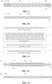
- Fig. 1 is a structural schematic diagram of a composite current collector provided in some other examples of the present application.
- the composite current collector 60 provided in the example of the present application comprises a support layer 70 and a conductive layer 80.
- the support layer 70 of the example of the present application functions to support and protect the conductive layer 80.
- the support layer 70 has two first surfaces 71 opposite to each other along a thickness direction X.
- the X direction illustrated in Fig. 1 indicates the thickness direction.
- the material of the support layer 70 comprises one or more of a polymer material and a polymer matrix composite material.
- the polymer matrix composite material comprises a polymer material and an additive, where the additive is at least one of an inorganic non-metallic material and a metallic material.
- the polymer material comprises at least one of polyamide, polyimide, polyethylene terephthalate, polybutylene terephthalate, polyethylene naphthalate, polycarbonate, polyethylene, polypropylene, polypropylene, acrylonitrile-butadiene-styrene copolymer, polyvinyl alcohol, polystyrene, polyvinyl chloride, polyvinylidene fluoride, polytetrafluoroethylene, sodium polystyrene sulfonate, polyacetylene, silicone rubber, polyformaldehyde, polyphenylene ether polyphenylene sulfide, polyethylene glycol, poly(sulfur nitride), polyphenylene, polypyrrole, polyaniline, polythiophene, polypyridine, cellulose, starch, protein, epoxy resin, phenolic resin, their derivatives, their cross-linkers, and their copolymers.
- the polymer material is at least one of polyamide, poly
- the polymer matrix composite material comprises a polymer material and an additive.
- the additive is at least one of an inorganic non-metallic material and a metallic material.
- the inorganic non-metallic material comprises one or more of a carbon-based material, alumina, silica, silicon nitride, silicon carbide, boron nitride, silicate, and titanium oxide.
- the metallic material comprises one or more of magnesium, calcium, strontium, lead, zinc, tin, antimony, bismuth, silver, and ruthenium.
- the conductive layer 80 of the example of the present application is provided on the two first surfaces 71 of the support layer 70.
- the conductive layer 80 can be formed on the support layer 70 by means of at least one of mechanical rolling, binding, vapor deposition, electroless plating, or electroplating, among which vapor deposition or electroplating may be selected, that is, the conductive layer 80 can be a vapor deposition layer or electroplated layer, so that a better tight bond between the conductive layer 80 and the support layer 70 can be achieved, and thus the support layer 70 can effectively function to support and protect the conductive layer 80.
- the conductive layer 80 can be connected to the support layer 70 by an adhesive, so as to improve the strength of connection between the conductive layer 80 and the support layer 70.
- the binder is selected from at least one of polypropylene, carboxymethyl cellulose, polyacrylate, styrene butadiene rubber, sodium polyacrylate, polyurethane, polyethyleneimine, polyvinylidene fluoride, chloroprene rubber, nitrile rubber, silicone rubber, polyvinyl acetate, urea-formaldehyde resin, phenolic resin, epoxy resin, silane coupling agent, titanate coupling agent, zirconium coupling agent, aluminate coupling agent and borate coupling agent.
- the material of the conductive layer 80 may include a metal.
- the conductive layer 80 is a positive conductive layer, and the material of the positive conductive layer is selected from aluminum or an aluminum-based alloy, which may be an aluminum-nickel alloy, an aluminum-titanium alloy, or an aluminum-silver alloy, etc.
- the conductive layer 80 is a negative conductive layer, and the material of the negative conductive layer is selected from copper or a copper-based alloy, which may be a copper-nickel alloy, copper-titanium alloy or copper-silver alloy, etc.
- the low melting point is relative to the main body material of the conductive layer 80.
- the main body material of the conductive layer 80 is aluminum
- the low-melting point metal refers to a metal of which the melting point is lower than that of the aluminum metal, and the melting point of the low-melting point organic conductive polymer layer is lower than that of the aluminum metal.
- the conductive layer 80 comprises a first portion 81 and a second portion 82.
- the first portion 81 comprises a first sub-portion 811 and a second sub-portion 812 provided on the two first surfaces 71, respectively
- the second portion 82 comprises a third sub-portion 821 and a fourth sub-portion 822, the third sub-portion 821 and the first sub-portion 811 being integrally provided, the fourth sub-portion 822 and the second sub-portion 812 being integrally provided, the third sub-portion 821 and the fourth sub-portion 822 both projecting from the support layer 70, and the third sub-portion 821 and the fourth sub-portion 822 being affixed to each other and fused as a whole.
- the third sub-portion 821 and the fourth sub-portion 822 are cut as a whole structure, and the cut edges are flush and burr-free, which can improve the safety performance and production yield of secondary batteries of the composite current collector 60.
- the first sub-portion 811 and the second sub-portion 812 of the first portion 81 are both provided on the first surface 71 for coating an active material layer.
- the third sub-portion 821 and the fourth sub-portion 822 of the second portion 82 are used as tabs.
- the first sub-portion 811 comprises two third surfaces 8111 opposite to each other along the thickness direction X.
- the third sub-portion 821 comprises two second surfaces 8211 opposite to each other along the thickness direction X.
- the first sub-portion 811 and the third sub-portion 821 are integrally provided, and one of the two third surfaces 8111 of the first sub-portion 811 may be flush with one of the two second surfaces 8211, or the first sub-portion 811 may project from the second surfaces 8211 or may be concave with respect to the second surfaces 8211.
- the second sub-portion 812 comprises two fourth surfaces opposite to each other along the thickness direction X.
- the fourth sub-portion 822 comprises two fifth surfaces opposite to each other along the thickness direction X.
- the second sub-portion 812 and the fourth sub-portion 822 are integrally provided, and one of the two fourth surfaces of the second sub-portion 812 may be flush with one of the two fifth surfaces, or the second sub-portion 812 may project from the fifth surface or may be concave with respect to the fifth surface.
- the first sub-portion 811 and the third sub-portion 821 are integrally provided, and the second sub-portion 812 and the fourth sub-portion 822 are integrally provided.
- the first sub-portion 811, the third sub-portion 821, the second sub-portion 812, and the fourth sub-portion 822 form the conductive layer 80
- the first sub-portion 811 and the second sub-portion 812 of the same thickness can be used, or the first sub-portion 811 and the second sub-portion 812 of different thicknesses can be used.
- the third sub-portion 821 and the fourth sub-portion 822 with the same thickness can be used, or the third sub-portion 821 and the fourth sub-portion 822 with different thickness can also be used.
- the first sub-portion 811 and the third sub-portion 821 are integrally provided
- the second sub-portion 812 and the fourth sub-portion 822 are integrally provided
- the third sub-portion 821 and the fourth sub-portion 822 are affixed to each other and fused as a whole.
- the conductive layer 80 is of an integral structure, and the configuration in which the conductive layer 80 is fused as a whole makes it possible that: 1) the disadvantages of the conventional welding process are avoided, the need for an externally connected metal foil is structurally eliminated, and the problem of poor welding of the externally connected metal foil to the conductive layer is avoided, thus significantly improving the over-current capability of the composite current collector 60, and improving the electrical performance of the secondary battery; 2) the hot melting process of the present application effectively avoids the cracking of the conductive layer 80 and the support layer 70 of the composite current collector 60 during the process, as well as the fracturing or even cracking of the root of the tab caused by processes (such as rolling), thus significantly increasing the production yield of the composite current collector 60 and the safety performance of secondary batteries; and 3) the machining consistency of composite current collectors 60 is improved, and the problem of misalignment of the top and bottom workpiece edges and burrs in the tab cutting process is avoided, which prevents folding of the tab during the die cutting and winding processes, thus improving the production yield
- the third sub-portion 821, an end portion 72 of the support layer 70 along the first direction Y, and the fourth sub-portion 822 are affixed to each other and fused as a whole.
- the Y direction illustrated in Fig. 1 indicates the first direction, with the first direction Y being perpendicular to the thickness direction X.
- the third sub-portion 821 and the end portion 72 as well as the fourth sub-portion 822 are fused as a whole.
- the three are connected to each other, and the end portion 72 can function to support and protect the third sub-portion 821 and the fourth sub-portion 822.
- the third sub-portion 821 and the fourth sub-portion 822 may be partially stretched, and the end portion 72 provides a support force for the third sub-portion 821 and the fourth sub-portion 822, thus making it possible to avoid fracturing or cracking of the third sub-portion 821 and the fourth sub-portion 822.
- the support layer 70 at the root of the tab after the tab is cut, which increases the stiffness of the root of the tab and prevents folding of the tab, thus significantly improving the safety performance during the preparation of secondary batteries.
- the end portion 72 along the first direction Y has a width of 1 mm to 10 mm.
- it may be 1 mm, 2 mm, 3 mm, 4 mm, 5 mm, 6 mm, 7 mm, 8 mm, 9 mm, or 10 mm; or the range of width may consist of any two of the aforementioned values; optionally, it may be 5 mm to 8 mm.
- the end portion 72 is in the above range of width, which can further improve the strength of connection of the end portion 72 with the third sub-portion 821 and the fourth sub-portion 822, and further improve the strength of support for the third sub-portion 821 and the fourth sub-portion 822.
- the width is measured in the following way: first, a micrometer is used to measure the thickness of the end portion 72, whereby the critical position of the end portion 72 near the first portion 81 and the critical position near the second portion 82 can be roughly determined; and then, near the critical positions, the composite current collector 60 is cut in section using an NEC IB-19500 and observed using a Zeiss Sigma 300 scanning electron microscope to further measure the thickness of the support layer 70 and the conductive layer 80 and to confirm a critical end face position; and after the end face position is determined, a scale is used to measure the width of the end portion 72.
- the dimension of C in Fig. 1 approximately represents the width dimension of the end portion 72 along the first direction Y.
- the first sub-portion 811 project with respect to the second surfaces 8211 of the third sub-portion 821 along the thickness direction X.
- the third sub-portion 821 has a relatively moderate thickness, which can improve to a large extent the energy density of the secondary battery that uses the composite current collector 60, while ensuring the over-current capability of the secondary battery that uses the composite current collector 60 and the safety performance of the secondary battery.
- Fig. 2 is a structural schematic diagram of a composite current collector provided in some other examples of the present application.
- one of the two third surfaces 8111 of the first sub-portion 811 is flush with the second surface 8211 of the third sub-portion 821.
- the first sub-portion 811 has a relatively small thickness, which can improve to some extent the energy density of the secondary battery that uses the composite current collector 60.
- the second sub-portion 812 project with respect to the fifth surface of the fourth sub-portion 822 along the thickness direction X.
- the fourth sub-portion 822 has a relatively moderate thickness, which can improve to a large extent the energy density of the secondary battery that uses the composite current collector 60, while ensuring the over-current capability of the secondary battery that uses the composite current collector 60.
- one of the two fourth surfaces of the second sub-portion 812 is flush with the fifth surface of the fourth sub-portion 822.
- the second sub-portion 812 has a relatively small thickness, which can improve to some extent the energy density of the secondary battery that uses the composite current collector 60.
- the first portion 81 has a thickness of A and the second portion 82 has a thickness of B, with A and B satisfying the following relation: 0.03 ⁇ A/B ⁇ 1.
- A/B is 0.03, 0.1, 0.2, 0.3, 0.4, 0.5, 0.6, 0.7, 0.8, 0.9, or 1; or the range of A/B ratio may be composed of any two of the aforementioned values; optionally, 0.2 ⁇ A/B ⁇ 1.
- the ratio of thickness of the first portion 81 and the second portion 82 satisfies the above range, which can ensure the energy density of the secondary battery that uses the composite current collector 60 and improve the over-current capability of the secondary battery.
- the thickness of the first portion 81 refers to the overall thickness of the first portion 81 along the thickness direction X.
- the first portion 81 comprises the first sub-portion 811 and the second sub-portion 812, and the thicknesses of the first sub-portion 811 and the second sub-portion 812 along the thickness direction X add up to A.
- the thickness of the second portion 82 refers to the overall thickness of the second portion 82 along the thickness direction X.
- the second portion 82 comprises the third sub-portion 821 and the fourth sub-portion 822, and the thicknesses of the third sub-portion 821 and the fourth sub-portion 822 along the thickness direction X add up to B.
- the second portion 82 further comprises other components such as a connecting layer, then the thicknesses of the third sub-portion 821, the connecting layer, and the fourth sub-portion 822 along the thickness direction X add up to B.
- the thickness A of the first portion 81 is 1 ⁇ m ⁇ A ⁇ 26 ⁇ m, for example, 1 um, 3 um, 6 um, 8 ⁇ m, 9 ⁇ m, 10 ⁇ m, 11 ⁇ m, 12 ⁇ m, 15 ⁇ m, 18 ⁇ m, 20 ⁇ m, 22 ⁇ m, 25 ⁇ m, and 26 um; or the range of thickness may be composed of any two of the aforementioned values.
- the thickness B of the second portion 82 is 5 ⁇ m ⁇ B ⁇ 26 ⁇ m, for example, 5 ⁇ m, 6 ⁇ m, 8 ⁇ m, 9 ⁇ m, 10 ⁇ m, 11 ⁇ m, 12 ⁇ m, 15 ⁇ m, 18 ⁇ m, 20 ⁇ m, 22 ⁇ m, 25 ⁇ m, 26 ⁇ m; or the range of thickness may be composed of any two of the aforementioned values.
- the first sub-portion 811 has a thickness greater than or equal to that of the second sub-portion 812. It is possible to not thin the second sub-portion 812 during the machining process, which can reduce the cost and facilitate machining and molding.
- the third sub-portion 821 has a thickness greater than or equal to that of the fourth sub-portion 822. It is possible to not thin the fourth sub-portion 822 during the machining process, which can reduce the cost and facilitate machining and molding.
- Fig. 3 is a structural schematic diagram of a composite current collector provided in some other examples of the present application.
- the second portion 82 further comprises a connecting layer 823 disposed between the third sub-portion 821 and the fourth sub-portion 822, and the connecting layer 823 has a melting point less than that of the third sub-portion 821.
- the connecting layer 823 has a relatively lower melting point, and when machining the second portion 82, the connecting layer 823 will be fused first, which facilitates adhering and affixing the third sub-portion 821 and the fourth sub-portion 822 as a whole, thus facilitating the fusion of the third sub-portion 821 and the fourth sub-portion 822 as a whole.
- the melting point of the connecting layer 823 is less than that of the fourth sub-portion 822, and the melting point of the connecting layer 823 is lower than those of both the third sub-portion 821 and the fourth sub-portion 822, which facilitates adhering and affixing the third sub-portion 821 and the fourth sub-portion 822 as a whole when machining the second portion 82.
- the connecting layer 823 comprises at least one of a metal layer and an organic conductive polymer layer.
- the connecting layer 823 is a metal layer, an organic conductive polymer layer, or a composite layer of a metal layer and an organic conductive polymer layer.
- the metal comprises at least one of tin, indium, bismuth, and cadmium.
- the metal is a single metal such as tin, indium, bismuth or cadmium; it can also be a tin-indium alloy, tin-bismuth alloy, tin-cadmium alloy, indium-bismuth alloy, bismuth-cadmium alloy, tin-indium-bismuth alloy or tin-bismuth-cadmium alloy.
- the connecting layer 823 is made of metal, it is more conducive to adequate fusion with the third sub-portion 821 and the fourth sub-portion 822.
- the metal layer may include one or more first sub-layers, and if multiple first sub-layers are used, each of the first sub-layers may be made of the same metal material or may be made of different materials.
- the organic conductive polymer comprises at least one of polypyrrole, polythiophene, polyaniline, polyacetylene, polyphenylene, and polyphenylene acetylene.
- the connecting layer 823 is made of organic conductive polymer, the organic conductive polymer can not only adhere the third sub-portion 821 and the fourth sub-portion 822, but also be fused and adhered with the support layer 70, thus enabling further improvement of the strength of connection between the second portion 82 and the support layer 70.
- the organic conductive polymer layer may include one or more second sub-layers, and if multiple second sub-layers are used, each of the second sub-layers may be made of the same organic conductive polymer material or may be made of different organic conductive polymer materials.
- the connecting layer 823 has a thickness of 1 ⁇ m to 5 ⁇ m, for example, 1 ⁇ m, 2 ⁇ m, 3 ⁇ m, 4 ⁇ m, or 5 ⁇ m; or the range of thickness may be composed of any two of the aforementioned values.
- the thickness of the connecting layer 823 is within the above range, it is conducive to assist adequate fusing and bonding of the third sub-portion 821 and the fourth sub-portion 822, that is, to facilitate adequate fusion of the second portion 82 into a whole.
- Fig. 4 is a structural schematic diagram of a composite current collector provided in some other examples of the present application.
- the support layer 70 comprises at least two support portions 73 spaced along the first direction Y, wherein the second portion 82 is provided between two adjacent support portions 73.
- the composite current collector 60 of this structure by slitting, can form components for multiple electrode assemblies.
- the support layer 70 comprises one support portion 73, and the second portion 82 projects from at least one end portion 72 of the support portion 73 along the first direction Y.
- the second portion 82 projects from one end portion 72 of the support portion 73 along the first direction Y, or from both end portions 72 of the support portion 73 along the first direction Y.
- Examples of the present application further provide a manufacturing method for a composite current collector.
- Fig. 5 is a schematic diagram of a manufacturing process for a composite current collector provided in some examples of the present application
- Fig. 6 is a state schematic diagram of a manufacturing process for a composite current collector provided in some examples of the present application
- Fig. 7 is another state schematic diagram of a manufacturing process for a composite current collector provided in some examples of the present application.
- the manufacturing method comprises the following steps:
- Fig. 8 is a flow chart of a manufacturing method for a composite current collector provided by some other examples of the present application
- Fig. 9 is another state schematic diagram of a manufacturing process for a composite current collector provided in some examples of the present application
- Fig. 10 is another state schematic diagram of a manufacturing process for a composite current collector provided in some examples of the present application.
- the arrows in Fig. 9 indicate the direction of thinning.
- step S300 after the step S300, the following steps are further included: S400: removing part of the first sub-portion along the thickness direction to thin the first sub-portion.
- the thickness of the first sub-portion is relatively lower, which can improve the energy density of the secondary battery to some extent.
- One of the two third surfaces 8111 of the thinned first sub-portion 811 can be flush with the second surface 8211 of the third sub-portion 821, and of course the thinned first sub-portion 811 can also project with respect to the second surfaces 8211 along the thickness direction X.
- a protective layer 100 can be provided on the second surfaces 8211 of the third sub-portion 821, and the first sub-portion 811 is thinned on the basis that the third sub-portion 821 contains the protective layer 100, and then, after the first sub-portion 811 is thinned, the protective layer 100 is removed. In this way, the thickness of the third sub-portion 821 is substantially unaffected.
- the material of the protective layer 100 is one or more of polymethyl methacrylate (PMMA), polymethacrylamide, polymethylisopropenyl ketone, polyisobutylene, or poly- ⁇ -methylstyrene. Such a protective layer 100 is capable of being dissolved and removed after the first sub-portion 811 is thinned.
- PMMA polymethyl methacrylate
- polymethacrylamide polymethacrylamide
- polymethylisopropenyl ketone polymethylisopropenyl ketone
- polyisobutylene poly- ⁇ -methylstyrene
- the following steps are further included: removing part of the second sub-portion along the thickness direction to thin the second sub-portion.
- step S400 The process of thinning the second sub-portion is as described in step S400 and will not be repeated herein.
- the reduced thicknesses of the first sub-portion and the second sub-portion due to thinning can be the same or different.
- Fig. 11 is a flow chart of a manufacturing method for a composite current collector provided by some other examples of the present application
- Fig. 12 is another state schematic diagram of a manufacturing process for a composite current collector provided in some examples of the present application
- Fig. 13 is another state schematic diagram of a manufacturing process for a composite current collector provided in some examples of the present application.
- the arrows in Fig. 12 indicate the direction of thinning.
- step S300 after the step S300, the following steps are further included: S500: removing part of the third sub-portion along the thickness direction to thin the third sub-portion.
- the first sub-portion 811 can project with respect to the second surfaces 8211 along the thickness direction X.
- a protective layer 100 can be provided on the third surfaces 8111 of the first sub-portion 811, and the third sub-portion 821 is thinned on the basis that the first sub-portion 811 contains the protective layer 100, and then, after the third sub-portion 821 is thinned, the protective layer 100 is removed. In this way, the thickness of the first sub-portion 811 is substantially unaffected.
- step S300 after the step S300, the following steps are further included:
- step S500 The process of thinning the fourth sub-portion is as described in step S500 and will not be repeated herein.
- the reduced thicknesses of the third sub-portion and the fourth sub-portion due to thinning can be the same or different.
- steps S300, steps S400 and S500 may also be included at the same time.
- step S500 is included.
- Examples of the present application further provide an electrode sheet.
- Fig. 14 is a structural schematic diagram of an electrode sheet provided in some examples of the present application; and Fig. 15 is a cross-sectional structural schematic diagram of an electrode sheet shown in Fig. 14 taken along the line A-A.
- the electrode sheet 50 of the example of the present application comprises a composite current collector 60 as described in any of the above examples of the present application and an active material layer 90, wherein the active material layer 90 is provided on the surface of the first portion 81 of the composite current collector 60.
- the secondary battery using the electrode sheet 50 of this structure has a more excellent electrochemical performance, especially its over-current capability and energy density.
- This electrode sheet 50 and the separator are formed into an electrode assembly by winding.
- the positive electrode sheet comprises a positive composite current collector and a positive active material layer.
- the main body material of the conductive layer of the positive composite current collector comprises aluminum or an aluminum-based alloy in the structural form of the composite current collector as described in any of the above examples of the present application.
- the positive active material used in the positive active material layer may be a positive active material known in the art for use in secondary batteries.
- the positive active material may include at least one of the following materials: lithium-containing phosphate with olivine structure, lithium transition metal oxide, and their respective modified compounds.
- the present application is not limited to these materials, and other conventional materials that can be used as positive active materials may also be used. It is possible to use only one of these positive active materials alone, or to use more than two in combination.
- examples of the lithium transition metal oxide may include, but are not limited to, at least one of a lithium-cobalt oxide (such as LiCoO 2 ), lithium-nickel oxide (such as LiNiO 2 ), lithium-manganese oxide (such as LiMnO 2 and LiMn 2 O 4 ), lithium-nickel-cobalt oxide, lithium-manganese-cobalt oxide, lithium-nickel-manganese oxide, lithium-nickel-cobalt-manganese oxide (such as LiNi 1/3 Co 1/3 Mn 1/3 O 2 (also abbreviated as NCM 333 ), LiNi 0.5 Co 0.2 Mn 0.3 O 2 (also abbreviated as NCM 523 ), LiNi 0.5 C 0.25 Mn 0.25 O 2 (also abbreviated as NCM 211 ), LiNi 0.6 Co 0.2 Mn 0.2 O 2 (also abbreviated as NCM 622 ), LiNi 0.8 Co 0.1 Mn 0.1 O 2 (also abbrevi
- lithium-containing phosphate with olivine structure may include, but are not limited to, at least one of lithium iron phosphate (such as LiFePO 4 (also abbreviated as LFP)), lithium iron phosphate-carbon composite, lithium manganese phosphate (such as LiMnPO 4 ), lithium manganese phosphate-carbon composite, lithium manganese iron phosphate, and lithium manganese iron phosphate-carbon composite.
- lithium iron phosphate such as LiFePO 4 (also abbreviated as LFP)
- LiMnPO 4 lithium manganese phosphate-carbon composite
- LiMnPO 4 lithium manganese phosphate-carbon composite
- manganese iron phosphate-carbon composite lithium manganese iron phosphate-carbon composite
- the positive active material layer may further optionally include a binder.
- the binder may include at least one of polyvinylidene fluoride (PVDF), polytetrafluoroethylene (PTFE), vinylidene fluoride-tetrafluoroethylene-propylene terpolymer, vinylidene fluoride-hexafluoropropylene-tetrafluoroethylene terpolymer, tetrafluoroethylene-hexafluoropropylene copolymer, and fluorinated acrylate resin.
- PVDF polyvinylidene fluoride
- PTFE polytetrafluoroethylene
- PTFE polytetrafluoroethylene
- vinylidene fluoride-hexafluoropropylene-tetrafluoroethylene terpolymer vinylidene fluoride-hexafluoropropylene-tetrafluoroethylene terpolymer
- the positive active material layer may further optionally include a conductive agent.
- the conductive agent may include at least one of superconducting carbon, acetylene black, carbon black, Ketjen black, carbon dots, carbon nanotubes, graphene, and carbon nanofibers.
- the positive electrode sheet can be prepared in the following manner: dispersing the above components for preparing the positive electrode sheet, such as the positive active material, the conductive agent, the second binder, and any other components, in a solvent (e.g., N-methyl pyrrolidone) to form a positive electrode slurry; and coating the positive electrode slurry on the positive composite current collector, and after processes such as oven drying and cold pressing, the positive electrode sheet can be obtained.
- a solvent e.g., N-methyl pyrrolidone
- the negative electrode sheet comprises a negative composite current collector and a negative active material layer.
- the main body material of the conductive layer of the negative composite current collector comprises copper or a copper-based alloy in the structural form of the composite current collector as described in any of the above examples of the present application.
- the negative active material in the negative active material layer may be a negative active material known in the art for use in secondary batteries.
- the negative active material may include at least one of the following materials: artificial graphite, natural graphite, soft carbon, hard carbon, silicon-based material, tin-based material, and lithium titanate, etc.
- the silicon-based material may be selected from at least one of monolithic silicon, silicon-oxygen compound, silicon-carbon composite, silicon-nitrogen composite, and silicon alloy.
- the tin-based material may be selected from at least one of monolithic tin, tin-oxygen compound, and tin alloy.
- the present application is not limited to these materials, and other conventional materials that can be used as battery negative active materials may also be used. It is possible to use only one of these negative active materials alone, or to use more than two in combination.
- the negative active material layer may further optionally include a binder.
- the binder may be selected from at least one of styrene butadiene rubber (SBR), polyacrylic acid (PAA), sodium polyacrylate (PAAS), polyacrylamide (PAM), polyvinyl alcohol (PVA), sodium alginate (SA), polymethacrylic acid (PMAA), and carboxymethyl chitosan (CMCS).
- the negative active material layer may further optionally include a conductive agent.
- the conductive agent may be selected from at least one of superconducting carbon, acetylene black, carbon black, Ketjen black, carbon dots, carbon nanotubes, graphene, and carbon nanofibers.
- the negative active material layer may further optionally include other additives, such as thickeners (e.g., sodium carboxymethyl cellulose (CMC-Na)), etc.
- thickeners e.g., sodium carboxymethyl cellulose (CMC-Na)
- the negative electrode sheet can be prepared in the following manner: dispersing the above components for preparing the negative electrode sheet, such as the negative active material, the conductive agent, the binder, and any other components, in a solvent (e.g., deionized water) to form a negative electrode slurry; and coating the negative electrode slurry on the negative composite current collector, and after processes such as oven drying and cold pressing, the negative electrode sheet can be obtained.
- a solvent e.g., deionized water
- the electrolyte plays the role of conduct ions between the positive electrode sheet and the negative electrode sheet.
- the type of electrolyte in the examples of the present application, and it can be selected according to the requirement.
- the electrolyte may be in a liquid, gel, or all-solid state.
- the electrolyte is an electrolyte solution.
- the electrolyte solution comprises an electrolyte salt and a solvent.
- the electrolyte salt may be selected from at least one of lithium hexafluorophosphate, lithium tetrafluoroborate, lithium perchlorate, lithium hexafluoroarsenate, lithium bis(fluorosulfonyl)imide, lithium bis(trifluoromethanesulfonyl)imide, lithium trifluoromethanesulfonate, lithium difluorophosphate, lithium difluoro(oxalato)borate, lithium bis(oxalato)borate, lithium difluoro bis(oxalato)phosphate, and lithium tetrafluoro(oxalato)phosphate.
- the solvent may be selected from at least one of ethylene carbonate, propylene carbonate, methylene carbonate, diethyl carbonate, dimethyl carbonate, dipropyl carbonate, methyl propyl carbonate, ethyl propyl carbonate, butylene carbonate, fluorinated ethylene carbonate, methyl formate, methyl acetate, ethyl acetate, propyl acetate, methyl propionate, ethyl propionate, propyl propionate, methyl butyrate, ethyl butyrate, 1,4-butyrolactone, sulfolane, dimethyl sulfone, methyl ethyl sulfone, and diethyl sulfone.
- the electrolyte solution may further optionally include an additive.
- the additive may include a negative electrode film-forming additive, positive electrode film-forming additive, and may also include additives that can improve certain battery properties, such as additives that improve battery overcharge performance, additives that improve battery high or low temperature performance, and the like.
- the secondary battery also comprises a separator.
- the examples of the present application have no particular limitation on the type of the separator, and any well-known porous structure separator with good chemical stability and mechanical stability can be used.
- the material of the separator can be selected from at least one of glass fiber, non-woven cloth, polyethylene, polypropylene, and polyvinylidene fluoride.
- the separator may be a single-layer film or a multi-layer composite film, which is not particularly limited.
- the material of each layer may be the same or different, which is not particularly limited.
- the positive electrode sheet, the negative electrode sheet, and the separator can be made into an electrode assembly by a winding process or a lamination process.
- the secondary battery may include an outer package. This outer package may be used to encapsulate the positive electrode sheet, the negative electrode sheet, the separator, and the electrolyte as described above.
- the outer package of the secondary battery may be a hard shell, e.g., a hard plastic shell, an aluminum shell, a steel shell, etc.
- the outer package of the secondary battery can also be a soft package, such as a pouch soft package.
- the material of the soft package can be plastic, and as plastic, polypropylene, polybutylene terephthalate, and polybutylene succinate can be enumerated.
- Examples of the present application further provide a secondary battery.
- Fig. 16 is a structural schematic diagram of an electrode assembly of a secondary battery provided in some examples of the present application
- Fig. 17 is an exploded schematic diagram of a secondary battery provided in some examples of the present application.
- the secondary battery 30 comprises a top cover assembly 31 and a case 32, and an electrode assembly 40 and an electrolyte accommodated within the case 32.
- the electrode assembly 40 comprises an electrode sheet 50 and a separator 41.
- the electrode sheet 50 comprises a positive electrode sheet and a negative electrode sheet.
- active ions are intercalated and deintercalated back and forth between the positive and negative electrode sheets.
- the electrolyte plays the role of conduct ions between the positive electrode sheet and the negative electrode sheet.
- the separator 41 is disposed between the positive electrode sheet and the negative electrode sheet, and mainly serves to prevent the short circuit of the positive and negative electrodes, and at the same time allows the ions to pass through.
- the secondary battery can be a wound or laminated battery, such as one of a lithium-ion secondary battery, lithium primary battery, sodium-ion battery, and magnesium-ion battery, but it is not limited to this.
- Fig. 14 illustrates a wound electrode assembly.
- the positive electrode sheet comprises the positive electrode sheet of the second aspect examples of the present application. Since the secondary battery 30 of the example of the present application employs the electrode sheet of the second aspect of the present application, it has a better electrochemical performance compared with the conventional secondary batteries. Accordingly, the negative electrode sheet may be a conventional negative electrode sheet in this field, or the negative electrode sheet of the second aspect examples of the present application.
- the negative electrode sheet comprises the negative electrode sheet of the second aspect examples of the present application. Since the secondary battery 30 of the example of the present application employs the electrode sheet of the second aspect of the present application, it has a better electrochemical performance compared with the conventional secondary batteries. Accordingly, the positive electrode sheet may be a conventional positive electrode sheet in this field.
- the positive electrode sheet comprises the positive electrode sheet of the second aspect examples of the present application.
- the negative electrode sheet comprises the negative electrode sheet of the second aspect examples of the present application. Since the secondary battery 30 of the example of the present application employs the electrode sheet of the second aspect of the present application, it has a better electrochemical performance compared with the conventional secondary batteries.
- Fig. 17 shows a secondary battery with a square structure as an example.
- the outer package of the secondary battery 30 may include the case 32 and the top cover assembly 31.
- the case 32 may include a bottom plate and side plates attached to the bottom plate, wherein the bottom plate and side plates enclose to form an accommodating cavity.
- the case 32 has an opening communicating with the accommodating cavity, and the top cover assembly 31 can cover the opening to close the accommodating cavity.
- the positive electrode sheet, the negative electrode sheet, and the separator 41 may form the electrode assembly 40 by a winding process or a lamination process.
- the electrode assembly 40 is encapsulated within the accommodating cavity.
- the electrolyte solution is infiltrated into the electrode assembly 40.
- the number of electrode assemblies 40 contained in the secondary battery 30 may be one or more, which may be selected by a person skilled in the art according to specific practical needs.
- the secondary battery 30 can be assembled into a battery module, and the number of secondary batteries contained in the battery module can be one or more, and the specific number can be selected by a person skilled in the art according to the application and capacity of the battery module.
- FIG. 18 is a partial structural schematic diagram of a battery module provided in some examples of the present application.
- a plurality of secondary batteries 30 may be arranged sequentially along the direction of length of the battery module 20. Of course, they can be arranged in any other way. The plurality of secondary batteries 30 may further be secured by fasteners.
- the battery module 20 may further include a shell having an accommodating space in which the plurality of secondary batteries 30 are accommodated.
- the above battery modules can also be assembled into a battery pack, and the number of battery modules contained in the battery pack can be one or more, and the specific number can be selected by a person skilled in the art according to the application and capacity of the battery pack.
- Fig. 19 is an exploded schematic diagram of a battery pack provided in some examples of the present application.
- a battery box as well as a plurality of battery modules 20 provided in the battery box may be included in the battery pack 10.
- the battery box comprises an upper box 12 and a lower box 11, wherein the upper box 12 can cover the lower box 11 and form an enclosed space for accommodating the battery modules 20.
- the plurality of battery modules 20 can be arranged in the battery box in an arbitrary manner.
- the present application further provides an electrical apparatus.
- Fig. 20 is a structural schematic diagram of an electrical apparatus provided in some examples of the present application.
- the electrical apparatus 1 comprises at least one of the secondary battery 30, the battery module, or the battery pack provided by the present application.
- the secondary battery 30, the battery module, or the battery pack may be used as a power source for the electrical apparatus or as an energy storage unit for the electrical apparatus.
- the electrical apparatus 1 may include a mobile device (e.g., a mobile phone, a laptop, etc.), an electric vehicle (e.g., all-electric vehicle, a hybrid electric vehicle, a plug-in hybrid electric vehicle, an electric bicycle, an electric scooter, an electric golf cart, an electric truck, etc.), an electric train, a ship and a satellite, and an energy storage system, etc., but is not limited thereto.
- the secondary battery, the battery module or the battery pack can be selected according to its usage needs.
- This electrical apparatus 1 is an all-electric vehicle, a hybrid electric vehicle, or a plug-in hybrid electric vehicle, etc.
- a battery pack or battery module may be used.
- the apparatus may be a mobile phone, a tablet, a laptop, etc.
- the device is generally required to be light and thin, and can use a secondary battery as a power source.
- a PET support layer (with a melting point of 251°C) with a thickness of 4.5 ⁇ m is selected, and the surface of the support layer is cleaned;
- the cathode active materials LiNi 0.8 Co 0.1 Mn 0.1 O 2 (NCM811), LiNi 0.5 Co 0.2 Mn 0.3 O 2 (NCM523), conductive carbon black, and binder polyvinylidene fluoride (PVDF) are mixed in an appropriate amount of N-methyl pyrrolidone (NMP) solvent with sufficient stirring in the weight ratio of 82:14:2:2 to form a uniform positive electrode slurry; and the positive electrode slurry is coated on the surface of the positive composite current collector, and a positive electrode sheet is obtained after oven drying, cold pressing, tab cutting, and other processes.
- NMP N-methyl pyrrolidone
- a copper foil with a thickness of 6 ⁇ m is used.
- the negative active material graphite, the conductive carbon black, the thickener sodium carboxymethyl cellulose (CMC), and the binder styrene butadiene rubber emulsion (SBR) are mixed in an appropriate amount of deionized water with sufficient stirring in the weight ratio of 96.5: 1.0: 1.0: 1.5 to form a uniform negative electrode slurry; and the negative electrode slurry is coated on the negative composite current collector, and a negative electrode sheet is obtained after oven drying and other processes.
- Ethylene carbonate (EC) and ethyl methyl carbonate (EMC) in a volume ratio of 3:7 are mixed uniformly to obtain the organic solvent, and then 1 mol/L of LiPF 6 is dissolved uniformly in the above organic solvent.
- the positive electrode sheet, the separator, and the negative electrode sheet are sequentially stacked, then wound into a battery cell and put into a package case, and the above electrolyte solution is injected into the battery cell, and then the secondary battery is obtained after the sealing, resting, hot and cold pressing, chemical formation, and other processes.
- Example 1 Unlike Example 1, the following steps are added after the hot pressing and fusing steps:
- Example 1 Unlike Example 1, the following steps are added after the hot pressing and fusing steps:
- Example 1 Unlike Example 1, the following steps are added after the hot pressing and fusing steps:
- Example 1 Unlike Example 1, the following steps are added after the hot pressing and fusing steps:
- a PMMA protective layer is arranged on the third and fourth sub-portions separately: a PMMA-anisole solution is purchased as the initial coating, Teflon is pasted to the back roller of the coating machine at the positions corresponding to the third and fourth sub-portions for the purpose of padding, and the sizes of pads are designed to correspond exactly to the third and fourth sub-portions, and only the positions of the third and fourth sub-portions are coated when the PMMA protective adhesive layer is applied, and the oven temperature is set to 80 to 100°C, and the final thickness of the protective layer is about 30 ⁇ m after oven baking with a coating speed of 8 m/min.
- the thickness of the first sub-portion is thinned by means of chemical etching: the composite current collector coated with the protective layer in specific areas is passed at a carrying speed of 11 m/min through an etching tank containing a NaOH solution at a solution temperature of 60°C, so as to thin the thickness of the conductive layer on which no PMMA protective layer is provided, and after washing and oven drying, the thickness of the first sub-portion is 3 ⁇ m;
- a PMMA protective layer is arranged on the second and fourth sub-portions: a PMMA-anisole solution is purchased as the initial coating, and the second and fourth sub-portions are coated using the coating machine, wherein the oven temperature is set to 80 to 100°C, and the coating speed is 8m/min, and the final thickness of the protective layer is about 30 ⁇ m.
- the thicknesses of the first sub-portion and the third sub-portion are thinned by means of chemical etching: the composite current collector coated with the protective layer in specific areas is passed at a carrying speed of 11 m/min through an etching tank containing a NaOH solution at a solution temperature of 60°C, so as to thin the thickness of the conductive layer on which no PMMA protective layer is provided, and after washing and oven drying, the thickness of the first sub-portion and the third sub-portion is 3 ⁇ m;
- Example 1 Unlike Example 1, the following steps are added after the hot pressing and fusing steps:
- Example 1 Unlike Example 1, the following steps are added after the hot pressing and fusing steps:
- Example 1 Unlike Example 1, the following steps are added after the hot pressing and fusing steps:
- Example 1 Unlike Example 1, the following steps are added after the hot pressing and fusing steps:
- Example 1 Unlike Example 1, the following steps are added after the hot pressing and fusing steps:
- Example 1 Unlike Example 1, the following steps are added after the hot pressing and fusing steps:
- APP support layer (with a melting point of 189°C) with a thickness of 4.5 ⁇ m is selected, and the surface of the support layer is cleaned;
- the negative active material graphite, the conductive carbon black, the thickener sodium carboxymethyl cellulose (CMC), and the binder styrene butadiene rubber emulsion (SBR) are mixed in an appropriate amount of deionized water with sufficient stirring in the weight ratio of 96.5: 1.0: 1.0: 1.5 to form a uniform negative electrode slurry; and the negative electrode slurry is coated on the negative composite current collector, and a negative electrode sheet is obtained after oven drying and other processes.
- An aluminum foil with a thickness of 13 ⁇ m is used.
- the cathode active materials LiNi 0.8 Co 0.1 Mn 0.1 O 2 (NCM811), LiNi 0.5 Co 0.2 Mn 0.3 O 2 (NCM523), conductive carbon black, and binder polyvinylidene fluoride (PVDF) are mixed in an appropriate amount of N-methyl pyrrolidone (NMP) solvent with sufficient stirring in the weight ratio of 82:14:2:2 to form a uniform positive electrode slurry; and the positive electrode slurry is coated on the positive composite current collector, and a positive electrode sheet is obtained after oven drying and other processes.
- NMP N-methyl pyrrolidone
- Ethylene carbonate (EC) and ethyl methyl carbonate (EMC) in a volume ratio of 3:7 are mixed uniformly to obtain the organic solvent, and then 1 mol/L of LiPF 6 is dissolved uniformly in the above organic solvent.
- the positive electrode sheet, the separator, and the negative electrode sheet are sequentially stacked, then wound into a battery cell and put into a package case, and the above electrolyte solution is injected into the battery cell, and then the secondary battery is obtained after the sealing, resting, hot and cold pressing, chemical formation, and other processes.
- a PP film material with a thickness of 4.5 ⁇ m is selected as the support layer, an aluminum foil with a thickness of 0.5 ⁇ m is arranged on the upper and lower surfaces as the conductive layer, and an externally connected aluminum foil is welded on the edge of the conductive layer through the transfer welding process for cutting the tabs.
- the secondary battery is charged for the first time with a current of 1C rate, and the charging is conducted at constant current and constant voltage with a termination voltage of 4.2V and a cutoff current of 0.05C; then it is discharged with a current of 1C rate and a discharge termination voltage of 2.8V, and the discharge capacity Cb and the discharge plateau voltage U are recorded at the first cycle of the secondary battery.
- Table 1 First portion Second portion A/B Connecting layer Performance of the secondary battery Thickne ss of the first sub-portion/ ⁇ m Thickne ss of the second sub-portion/ ⁇ m A/ ⁇ m Thickne ss of the third sub-portion/ ⁇ m Thickne ss of the fourth sub-portion/ ⁇ m B/ ⁇ m Materi al Thick ness/ ⁇ m Energy density of the seconda ry battery/( Wh/L) Over-current capability DCR(m ⁇ )
- Example 1 5 5 10 5 5 10 1 / / 475 1.50
- Example 2 3 3 6 5 5 10 0.6 / / 488 1.53
- Comparative Example 1 a transfer welding process is used to weld the edges of the conductive layer and the externally connected aluminum foil, and thus there are two separate layers of aluminum foil on the top and bottom in the welding zone, and there exists welding in the welding zone.
- This welding method will limit the welding strength to a certain extent, and will increase the thickness of the tabs in the welding zone, in which case, although the over-current capability can be improved, the over-current capability and energy density of the secondary battery are relatively low.
- Comparative Example 5 uses hot-melt connection, and the over-current capability and energy density of its secondary battery are significantly improved.
- Example 1 As the thickness of the first portion decreases, the A/B value gradually decreases and the energy density of the secondary battery gradually increases, but at the same time, the DCR also gradually increases. As can be seen from Table 1, when A/B is 0.2 to 1, the energy density and DCR of the secondary battery are superior. When A/B ⁇ 0.2, DCR increases significantly.
- Examples 10 to 13 by adding a metal connecting layer or a conductive polymer connecting layer between the third sub-portion and the fourth sub-portion, the temperature of the hot-press fusion can be reduced and the machining difficulty can be reduced, especially the temperature of the hot-press fusion can be reduced to, for example, below 400°C; and the secondary battery of Examples 10 to 12 can maintain an energy density and over-current capability similar to those of the direct hot-press fusion of Example 1. It can be seen that the metal connecting layer facilitates the machining of the composite current collector, and substantially has no adverse effect on the energy density and over-current capability of the secondary battery.
- the energy density and over-current capability of the secondary battery of Example 14 are excellent, so it can be seen that the composite current collector of the examples of the present application is not only suitable for the preparation of a positive composite current collector, but also suitable for a negative composite current collector, and is thus universal.
Landscapes
- Chemical & Material Sciences (AREA)
- Chemical Kinetics & Catalysis (AREA)
- Electrochemistry (AREA)
- General Chemical & Material Sciences (AREA)
- Engineering & Computer Science (AREA)
- Materials Engineering (AREA)
- Manufacturing & Machinery (AREA)
- Composite Materials (AREA)
- Connection Of Batteries Or Terminals (AREA)
- Cell Electrode Carriers And Collectors (AREA)
Abstract
Description
- The present application relates to the technical field of batteries, and in particular to a composite current collector, an electrode sheet, a secondary battery, a battery module, a battery pack, and an electrical apparatus.
- Secondary batteries are widely used in electric vehicles and consumer electronics because of their high energy density, high output power, long cycle life and low environmental pollution. As an important component in the preparation of secondary batteries, the composite current collector has a significant impact on the electrochemical performance of secondary batteries. Compared with conventional composite current collectors, the sandwich structure of "metal-insulating polymer-metal" can effectively improve the electrochemical performance of the secondary batteries. However, there are many problems in the existing composite current collectors, such as the poor over-current capability caused by insufficient bonding strength between the composite current collector and the externally connected metal foil (for machining tabs), and the complicated preparation process, which have a significant impact on the electrical performance, safety performance, and machining performance of the secondary batteries. Therefore, there is an urgent need to develop a new type of composite current collector.
- The present application is conducted in view of the above problems, and its purpose is to provide a composite current collector, an electrode sheet, a secondary battery, a battery module, a battery pack, and an electrical apparatus.
- In order to achieve the above purpose, the first aspect examples of the present application provide a composite current collector that comprises a support layer and a conductive layer. The support layer has two first surfaces opposite to each other along a thickness direction. The conductive layer is provided on the two first surfaces, and the conductive layer comprises a first portion and a second portion, wherein the first portion comprises a first sub-portion and a second sub-portion provided on the two first surfaces, respectively, and the second portion comprises a third sub-portion and a fourth sub-portion, the third sub-portion and the first sub-portion being integrally provided, the fourth sub-portion and the second sub-portion being integrally provided, the third sub-portion and the fourth sub-portion both projecting from the support layer, and the third sub-portion and the fourth sub-portion being affixed to each other and fused as a whole.
- Thus, in the examples of the present application, the first sub-portion and the third sub-portion are integrally provided, the second sub-portion and the fourth sub-portion are integrally provided, the third sub-portion and the fourth sub-portion are affixed to each other and fused as a whole. That is, the conductive layer is of an integral structure, and the configuration in which the conductive layer is fused as a whole makes it possible that: 1) the disadvantages of the conventional welding process are avoided, the need for an externally connected metal foil is structurally eliminated, and the problem of poor welding of the externally connected metal foil to the conductive layer is avoided, thus significantly improving the over-current capability of the composite current collector, and improving the electrical performance of the secondary battery; 2) the hot melting process of the present application effectively avoids the cracking of the conductive layer and the support layer of the composite current collector during the production process, as well as the fracturing or even cracking of the root of the tab caused by processes (such as rolling), thus significantly increasing the production yield of the composite current collector and the safety performance of secondary batteries; and 3) the machining consistency of composite current collectors is improved, and the problem of misalignment of the top and bottom workpiece edges and burrs in the tab cutting process is avoided, which prevents folding of the die cutting and winding processes, thus improving the production yield and safety performance. In conclusion, the composite current collector of the present application can significantly improve the electrical performance, safety performance, and production yield of secondary batteries.
- In any of embodiments, the third sub-portion, an end portion of the support layer along the first direction, and the fourth sub-portion are affixed to each other and fused as a whole, wherein the first direction is perpendicular to the thickness direction; and the end portion can function to support and protect the third sub-portion and the fourth sub-portion.
- In the subsequent processes such as rolling, the third sub-portion and the fourth sub-portion may be partially stretched, and the end portion provides a support force for the third sub-portion and the fourth sub-portion, thus making it possible to avoid fracturing or cracking of the third sub-portion and the fourth sub-portion. In addition, for the composite current collector of this embodiment, there exists support of the support layer at the root of the tab after the tab is cut, which increases the stiffness of the root of the tab and prevents folding of the tab, thus significantly improving the safety performance during the preparation of secondary batteries.
- In any of embodiments, the end portion along the first direction has a width of 1 mm to 10 mm, optionally 5 mm to 8 mm. The end portion is in the above range of width, which can further improve the strength of connection of the end portion with the third sub-portion and the fourth sub-portion, and further improve the strength of support for the third sub-portion and the fourth sub-portion.
- In any of embodiments, the third sub-portion comprises two second surfaces opposite to each other along the thickness direction, and the first sub-portion projects with respect to the second surfaces along the thickness direction.
- As a result, the third sub-portion of the examples of the present application has a relatively moderate thickness, which can improve the energy density of a secondary battery using the composite current collector to a large extent, while ensuring the over-current capability of the secondary battery that uses the composite current collector and the safety performance of the secondary battery.
- In any of embodiments, the third sub-portion comprises two second surfaces opposite to each other along the thickness direction; and the first sub-portion comprises two third surfaces opposite to each other along the thickness direction, one of the two third surfaces being flush with the second surface.
- As a result, the first sub-portion of the examples of the present application has a relatively small thickness, which can improve to some extent the energy density of a secondary battery that uses the composite current collector.
- In any of embodiments, the first portion has a thickness of A and the second portion has a thickness of B, wherein 0.03 ≤ A/B ≤ 1; optionally, 0.2 ≤ A/B ≤ 1. The ratio of thickness of the first portion and the second portion falls within the above range, which can ensure the energy density of the secondary battery that uses the composite current collector and improve the over-current capability of the secondary battery.
- In any of embodiments, the first sub-portion has a thickness greater than or equal to that of the second sub-portion. It is possible to not thin the second sub-portion during the machining process, which can reduce the cost and facilitate machining and molding.
- In any of embodiments, the third sub-portion has a thickness greater than or equal to that of the fourth sub-portion. It is possible to not thin the fourth sub-portion during the machining process, which can reduce the cost and facilitate machining and molding.
- In any of embodiments, the second portion further comprises a connecting layer disposed between the third sub-portion and the fourth sub-portion, and the connecting layer has a melting point less than that of the third sub-portion.
- As a result, the connecting layer has a relatively lower melting point, and when machining the second portion, the connecting layer will be fused first, which facilitates adhering and affixing the third sub-portion and the fourth sub-portion as a whole, thus facilitating the fusing of the third sub-portion and the fourth sub-portion as a whole.
- In any of embodiments, the connecting layer comprises at least one of a metal layer and an organic conductive polymer layer. Optionally, the metal comprises at least one of tin, indium, bismuth, and cadmium. Optionally, the organic conductive polymer comprises at least one of polypyrrole, polythiophene, polyaniline, polyacetylene, polyphenylene, and polyphenylene acetylene. When the connecting layer is made of metal, it is more conducive to adequate fusing with the third sub-portion and the fourth sub-portion. When the connecting layer is made of organic conductive polymer, the organic conductive polymer can not only adhere the third sub-portion and the fourth sub-portion, but also be fused and affixed with the support layer, thus enabling further improvement of the strength of connection between the second portion and the support layer.
- In any of embodiments, the connecting layer has a thickness of 1 µm to 5 µm. When the thickness of the connecting layer is within the above range, it is conducive to assist adequate fusing and bonding of the third sub-portion and the fourth sub-portion, that is, to facilitate adequate fusing of the second portion into a whole.
- In any of embodiments, the support layer comprises at least two support portions spaced along a first direction, wherein the second portion is provided between two adjacent support portions, and the first direction is perpendicular to the thickness direction. The composite current collector of this structure, by slitting, can form components for multiple electrode assemblies.
- A second aspect of the present application provides an electrode sheet comprising a composite current collector as described in any of the examples of the first aspect of the present application and an active material layer, wherein the active material layer is provided on the surface of the first portion of the composite current collector.
- A third aspect of the present application provides a secondary battery comprising an electrode sheet as described in the second aspect examples of the present application.
- A fourth aspect of the present application provides a battery module comprising a secondary battery as described in the third aspect examples of the present application.
- A fifth aspect of the present application provides a battery pack comprising a secondary battery as described in the third aspect examples of the present application or a battery module as described in the fourth aspect examples of the present application.
- A sixth aspect of the present application provides an electrical apparatus comprising a secondary battery as described in the third aspect examples of the present application, a battery module as described in the fourth aspect examples of the present application, or a battery pack as described in the fifth aspect of the present application.
- A seventh aspect of the present application provides a manufacturing method for a composite current collector, comprising: providing a support layer that comprises two first surfaces opposite to each other along a thickness direction; providing a first conductive sheet and a second conductive sheet, and connecting the first conductive sheet and the second conductive sheet to the two first surfaces, respectively, wherein the first conductive sheet comprises a first sub-portion and a third sub-portion, and the second conductive sheet comprises a second sub-portion and a fourth sub-portion, the first sub-portion and the second sub-portion being provided on the two first surfaces, respectively, and the third sub-portion and the fourth sub-portion both projecting from the support layer; and the third sub-portion and the fourth sub-portion are affixed to each other and fused as a whole.
- Therefore, the composite current collector prepared by the manufacturing method of the example of the present application does not require transfer welding, but can be directly subjected to laser die cutting to obtain a tab, which greatly simplifies the process and improves the over-current capability of the tab. Moreover, the edges are flush without burrs during the process of mechanical slitting, and the conductive layer of the second portion is well connected with the support layer, so that there will be no cracking and other problems in the cold pressing process. Therefore, the electrochemical performance of the secondary battery prepared using this composite current collector is excellent.
- In any of embodiments, this method further comprises: removing part of the first sub-portion along the thickness direction to thin the first sub-portion. The first sub-portion has a relatively lower thickness, which can improve the energy density of the secondary battery to some extent.
- In any of embodiments, this method further comprises: removing part of the third sub-portion along the thickness direction to thin the third sub-portion. By thinning the third sub-portion, it is possible to improve the energy density while ensuring the over-current capability.
- In order to illustrate the technical solutions of the examples of the present application more clearly, the following briefly introduces the drawings required in the examples of the present application. Obviously, the drawings described below are only some examples of the present application. For those of ordinary skill in the art, other drawings can also be obtained according to the drawings without any creative effort.
-
Fig. 1 is a structural schematic diagram of a composite current collector provided in some examples of the present application; -
Fig. 2 is a structural schematic diagram of a composite current collector provided in some other examples of the present application; -
Fig. 3 is a structural schematic diagram of a composite current collector provided in some other examples of the present application; -
Fig. 4 is a structural schematic diagram of a composite current collector provided in some other examples of the present application; -
Fig. 5 is a schematic diagram of a manufacturing process for a composite current collector provided in some examples of the present application; -
Fig. 6 is a state schematic diagram of a manufacturing process for a composite current collector provided in some examples of the present application; -
Fig. 7 is another state schematic diagram of a manufacturing process for a composite current collector provided in some examples of the present application; -
Fig. 8 is a flow chart of a manufacturing method for a composite current collector provided in some other examples of the present application; -
Fig. 9 is another state schematic diagram of a manufacturing process for a composite current collector provided in some examples of the present application; -
Fig. 10 is another state schematic diagram of a manufacturing process for a composite current collector provided in some examples of the present application; -
Fig. 11 is a flow chart of a manufacturing method for a composite current collector provided in some other examples of the present application; -
Fig. 12 is another state schematic diagram of a manufacturing process for a composite current collector provided in some examples of the present application; -
Fig. 13 is another state schematic diagram of a manufacturing process for a composite current collector provided in some examples of the present application; -
Fig. 14 is a structural schematic diagram of an electrode sheet provided in some examples of the present application; -
Fig. 15 is a cross-sectional structural schematic diagram of an electrode sheet shown inFig. 14 taken along the line A-A; -
Fig. 16 is a structural schematic diagram of an electrode assembly of a secondary battery provided in some examples of the present application; -
Fig. 17 is an exploded schematic diagram of a secondary battery provided in some examples of the present application; -
FIG. 18 is a partial structural schematic diagram of a battery module provided in some examples of the present application; -
Fig. 19 is an exploded schematic diagram of a battery pack provided in some examples of the present application; and -
Fig. 20 is a structural schematic diagram of an electrical apparatus provided in some examples of the present application. - In the accompanying drawings, the accompanying drawings are not necessarily drawn to actual scale.
- Here, the reference numerals in the drawings are as follows:
- X, thickness direction; Y, first direction;
- 1, electrical apparatus; 10, battery pack; 11, lower box; 12, upper box; 20, battery module; 30, secondary battery; 31, top cover assembly; 32, case; 40, electrode assembly; 50, electrode sheet; 41, separator;
- 60, composite current collector;
- 70, support layer; 71, first surface; 72, end portion; 73, support portion;
- 80, conductive layer; 81, first portion; 811, first sub-portion; 8111, third surface; 812, second sub-portion; 82, second portion; 821, third sub-portion; 8211, second surface; 822, fourth sub-portion; 823, connecting layer;
- 90, active material layer;
- 100, a protective layer.
- Hereinafter, the embodiments of a composite current collector and its manufacturing method, an electrode sheet, a secondary battery, a battery module, a battery pack, and an electrical apparatus of the present application are specifically disclosed in detail with reference to the accompanying drawings as appropriate. However, there are cases where unnecessary detailed descriptions are omitted. For example, there are cases where detailed descriptions of well-known items and repeated descriptions of actually identical structures are omitted. This is to avoid unnecessary redundancy in the following descriptions and to facilitate the understanding by those skilled in the art. In addition, the drawings and subsequent descriptions are provided for those skilled in the art to fully understand the present application, and are not intended to limit the subject matter recited in the claims.
- The "range" disclosed in the present application is defined in terms of lower and upper limits, and a given range is defined by selecting a lower limit and an upper limit, which define the boundaries of a particular range. A range defined in this manner may be inclusive or exclusive of end values, and may be arbitrarily combined, that is, any lower limit may be combined with any upper limit to form a range. For example, if a range of 60-120 and 80-110 is listed for a particular parameter, it is understood that a range of 60-110 and 80-120 is also expected. Additionally, if the
minimum range values 1 and 2 are listed, and if the maximum range values 3, 4, and 5 are listed, the following ranges are all contemplated: 1-3, 1-4, 1-5, 2- 3, 2-4 and 2-5. In the present application, unless stated otherwise, the numerical range "a-b" represents an abbreviated representation of any combination of real numbers between a and b, where both a and b are real numbers. For example, the numerical range "0-5" means that all real numbers between "0-5" have been listed herein, and "0-5" is just an abbreviated representation of the combination of these numerical values. Additionally, when it is stated that a certain parameter is an integer of ≥2, it is equivalent to disclosing that the parameter is, for example, an integer of 2, 3, 4, 5, 6, 7, 8, 9, 10, 11, 12, etc. - Unless otherwise specified, all embodiments and optional embodiments of the present application may be combined with each other to form new technical solutions. Unless otherwise specified, all technical features and optional technical features of the present application may be combined with each other to form new technical solutions.
- If not specifically stated, all steps of the present application may be performed sequentially or randomly, preferably sequentially. For example, the method comprises steps (a) and (b), indicating that the method may include steps (a) and (b) performed sequentially, or may include steps (b) and (a) performed sequentially. For example, when it is mentioned that the method can also include step (c), it means that step (c) can be added to the method in any order. For example, the method can include steps (a), (b), and (c), or steps (a), (c), and (b), or steps (c), (a), and (b).
- If not specifically stated, "comprising" and "containing" mentioned in the present application indicate open inclusion or closed inclusion. For example, "comprising" and " containing" may indicate that other components not listed may also be included or contained, or only the listed components may be included or contained.
- If not specifically stated, the term "or" is inclusive in the present application. By way of example, the phrase "A or B" means "A, B, or both A and B." More specifically, the condition "A or B" is satisfied by any of the following: A is true (or present) and B is false (or absent); A is false (or absent) and B is true (or present); or both A and B are true (or present).
- It is to be understood that relational terms such as "first", "second", etc., are used only to distinguish one entity or operation from another and do not necessarily require or imply any actual relationship or order between these entities or operations.
- The foregoing Summary of the Invention are not intended to describe every disclosed embodiment or every implementation of the present application. The following description illustrates exemplary embodiments in more detail. In various places throughout the present application, guidance is provided through a series of examples, and these examples can be used in various combinations. In each example, the enumeration is performed to give only representative groups and should not be interpreted as exhaustive.
- The inventor found that the "sandwich" composite current collector composed of a support layer and a conductive layer located on the two opposite surfaces of the support layer has many defects, which may cause the electrical performance, safety performance, and machining performance of the secondary battery to fail to meet the requirements of large-scale industrialization. Specifically:
- For a composite current collector in the prior art, the main body thereof is composed of a support layer and a conductive layer on the surfaces of the support layer. In order for the current collected in the main body to be output outwards/the external current to charge the secondary battery, the preparation process of the composite current collector requires the external connection of a metal foil on the surface of the conductive layer (the externally connected metal foil is used for machining a tab), with the external connection being conducted by welding (also known as "transfer welding" in the industry). However, there are many defects in this welding connection mode: 1) due to the thin conductive layer of the composite current collector, this conventional welding process makes the connection strength between the externally connected metal foil and the conductive layer insufficient, which leads to the problem of pseudo welding, and then leads to the limitation of the over-current capability in the welding area, which affects the electrical performance of the secondary battery; 2) insufficient welding strength also makes the externally connected metal foil and the main body easily fall off in the subsequent preparation processes such as cold pressing and die cutting, which significantly reduces the production yield of composite current collectors and the safety performance of the secondary battery; 3) in order to machine tabs, both the two conductive layers need to be externally connected with metal foils, which makes the upper and lower layers of metal foils need to be processed separately when cutting the tabs on the externally connected metal foil, which leads to the problems of edge misalignment and burrs of the cut upper and lower tabs, reducing the production yield and safety performance; and 4) the composite current collector prepared by the conventional transfer welding process lacks the support of the support layer at the root of the tab after the tab is cut, resulting in the tab being prone to folding, which significantly reduces the safety performance of the secondary battery in the preparation process.
- Based on the above defects of the existing composite current collector, a composite current collector that can significantly improve the electrical performance, safety performance, and machining performance of secondary batteries has been developed in the present application. Next, a detailed description of the examples of the present application is provided in conjunction with
Figs. 1 to 20 . -
Fig. 1 is a structural schematic diagram of a composite current collector provided in some other examples of the present application. - As shown in
Fig. 1 , the compositecurrent collector 60 provided in the example of the present application comprises asupport layer 70 and aconductive layer 80. - The
support layer 70 of the example of the present application functions to support and protect theconductive layer 80. Thesupport layer 70 has twofirst surfaces 71 opposite to each other along a thickness direction X. The X direction illustrated inFig. 1 indicates the thickness direction. - The material of the
support layer 70 comprises one or more of a polymer material and a polymer matrix composite material. The polymer matrix composite material comprises a polymer material and an additive, where the additive is at least one of an inorganic non-metallic material and a metallic material. - The polymer material comprises at least one of polyamide, polyimide, polyethylene terephthalate, polybutylene terephthalate, polyethylene naphthalate, polycarbonate, polyethylene, polypropylene, polypropylene, acrylonitrile-butadiene-styrene copolymer, polyvinyl alcohol, polystyrene, polyvinyl chloride, polyvinylidene fluoride, polytetrafluoroethylene, sodium polystyrene sulfonate, polyacetylene, silicone rubber, polyformaldehyde, polyphenylene ether polyphenylene sulfide, polyethylene glycol, poly(sulfur nitride), polyphenylene, polypyrrole, polyaniline, polythiophene, polypyridine, cellulose, starch, protein, epoxy resin, phenolic resin, their derivatives, their cross-linkers, and their copolymers. Optionally, the polymer material is at least one of polyamide, polyimide, polyethylene terephthalate, polypropylene, and polyphenylene sulfide.
- The polymer matrix composite material comprises a polymer material and an additive. The additive is at least one of an inorganic non-metallic material and a metallic material. Optionally, the inorganic non-metallic material comprises one or more of a carbon-based material, alumina, silica, silicon nitride, silicon carbide, boron nitride, silicate, and titanium oxide. The metallic material comprises one or more of magnesium, calcium, strontium, lead, zinc, tin, antimony, bismuth, silver, and ruthenium.
- The
conductive layer 80 of the example of the present application is provided on the twofirst surfaces 71 of thesupport layer 70. Theconductive layer 80 can be formed on thesupport layer 70 by means of at least one of mechanical rolling, binding, vapor deposition, electroless plating, or electroplating, among which vapor deposition or electroplating may be selected, that is, theconductive layer 80 can be a vapor deposition layer or electroplated layer, so that a better tight bond between theconductive layer 80 and thesupport layer 70 can be achieved, and thus thesupport layer 70 can effectively function to support and protect theconductive layer 80. - In some examples, the
conductive layer 80 can be connected to thesupport layer 70 by an adhesive, so as to improve the strength of connection between theconductive layer 80 and thesupport layer 70. Exemplarily, the binder is selected from at least one of polypropylene, carboxymethyl cellulose, polyacrylate, styrene butadiene rubber, sodium polyacrylate, polyurethane, polyethyleneimine, polyvinylidene fluoride, chloroprene rubber, nitrile rubber, silicone rubber, polyvinyl acetate, urea-formaldehyde resin, phenolic resin, epoxy resin, silane coupling agent, titanate coupling agent, zirconium coupling agent, aluminate coupling agent and borate coupling agent. - The material of the
conductive layer 80 may include a metal. Exemplarily, when the compositecurrent collector 60 is a positive composite current collector, theconductive layer 80 is a positive conductive layer, and the material of the positive conductive layer is selected from aluminum or an aluminum-based alloy, which may be an aluminum-nickel alloy, an aluminum-titanium alloy, or an aluminum-silver alloy, etc. When the compositecurrent collector 60 is a negative composite current collector, theconductive layer 80 is a negative conductive layer, and the material of the negative conductive layer is selected from copper or a copper-based alloy, which may be a copper-nickel alloy, copper-titanium alloy or copper-silver alloy, etc. - Of course, in some examples, in the process of forming the
conductive layer 80, other substances that facilitate machining, such as a low-melting point metal or a low-melting point organic conductive polymer layer, can also be added. Herein, the low melting point is relative to the main body material of theconductive layer 80. Exemplarily, the main body material of theconductive layer 80 is aluminum, and the low-melting point metal refers to a metal of which the melting point is lower than that of the aluminum metal, and the melting point of the low-melting point organic conductive polymer layer is lower than that of the aluminum metal. - The
conductive layer 80 comprises afirst portion 81 and asecond portion 82. Thefirst portion 81 comprises afirst sub-portion 811 and asecond sub-portion 812 provided on the twofirst surfaces 71, respectively, and thesecond portion 82 comprises athird sub-portion 821 and afourth sub-portion 822, thethird sub-portion 821 and thefirst sub-portion 811 being integrally provided, thefourth sub-portion 822 and thesecond sub-portion 812 being integrally provided, thethird sub-portion 821 and thefourth sub-portion 822 both projecting from thesupport layer 70, and thethird sub-portion 821 and thefourth sub-portion 822 being affixed to each other and fused as a whole. Thethird sub-portion 821 and thefourth sub-portion 822 are cut as a whole structure, and the cut edges are flush and burr-free, which can improve the safety performance and production yield of secondary batteries of the compositecurrent collector 60. - The
first sub-portion 811 and thesecond sub-portion 812 of thefirst portion 81 are both provided on thefirst surface 71 for coating an active material layer. Thethird sub-portion 821 and thefourth sub-portion 822 of thesecond portion 82 are used as tabs. - The
first sub-portion 811 comprises twothird surfaces 8111 opposite to each other along the thickness direction X. Thethird sub-portion 821 comprises twosecond surfaces 8211 opposite to each other along the thickness direction X. Thefirst sub-portion 811 and thethird sub-portion 821 are integrally provided, and one of the twothird surfaces 8111 of thefirst sub-portion 811 may be flush with one of the twosecond surfaces 8211, or thefirst sub-portion 811 may project from thesecond surfaces 8211 or may be concave with respect to the second surfaces 8211. - The
second sub-portion 812 comprises two fourth surfaces opposite to each other along the thickness direction X. Thefourth sub-portion 822 comprises two fifth surfaces opposite to each other along the thickness direction X. Thesecond sub-portion 812 and thefourth sub-portion 822 are integrally provided, and one of the two fourth surfaces of thesecond sub-portion 812 may be flush with one of the two fifth surfaces, or thesecond sub-portion 812 may project from the fifth surface or may be concave with respect to the fifth surface. - The
first sub-portion 811 and thethird sub-portion 821 are integrally provided, and thesecond sub-portion 812 and thefourth sub-portion 822 are integrally provided. When thefirst sub-portion 811, thethird sub-portion 821, thesecond sub-portion 812, and thefourth sub-portion 822 form theconductive layer 80, thefirst sub-portion 811 and thesecond sub-portion 812 of the same thickness can be used, or thefirst sub-portion 811 and thesecond sub-portion 812 of different thicknesses can be used. Thethird sub-portion 821 and thefourth sub-portion 822 with the same thickness can be used, or thethird sub-portion 821 and thefourth sub-portion 822 with different thickness can also be used. - In the examples of the present application, the
first sub-portion 811 and thethird sub-portion 821 are integrally provided, thesecond sub-portion 812 and thefourth sub-portion 822 are integrally provided, thethird sub-portion 821 and thefourth sub-portion 822 are affixed to each other and fused as a whole. That is, theconductive layer 80 is of an integral structure, and the configuration in which theconductive layer 80 is fused as a whole makes it possible that: 1) the disadvantages of the conventional welding process are avoided, the need for an externally connected metal foil is structurally eliminated, and the problem of poor welding of the externally connected metal foil to the conductive layer is avoided, thus significantly improving the over-current capability of the compositecurrent collector 60, and improving the electrical performance of the secondary battery; 2) the hot melting process of the present application effectively avoids the cracking of theconductive layer 80 and thesupport layer 70 of the compositecurrent collector 60 during the process, as well as the fracturing or even cracking of the root of the tab caused by processes (such as rolling), thus significantly increasing the production yield of the compositecurrent collector 60 and the safety performance of secondary batteries; and 3) the machining consistency of compositecurrent collectors 60 is improved, and the problem of misalignment of the top and bottom workpiece edges and burrs in the tab cutting process is avoided, which prevents folding of the tab during the die cutting and winding processes, thus improving the production yield and safety performance. In conclusion, the composite current collector of the present application can significantly improve the electrical performance, safety performance, and production yield of secondary batteries. - Referring further to
Fig. 1 , in some embodiments, thethird sub-portion 821, anend portion 72 of thesupport layer 70 along the first direction Y, and thefourth sub-portion 822 are affixed to each other and fused as a whole. The Y direction illustrated inFig. 1 indicates the first direction, with the first direction Y being perpendicular to the thickness direction X. - The
third sub-portion 821 and theend portion 72 as well as thefourth sub-portion 822 are fused as a whole. In other words, the three are connected to each other, and theend portion 72 can function to support and protect thethird sub-portion 821 and thefourth sub-portion 822. In the subsequent processes such as rolling, thethird sub-portion 821 and thefourth sub-portion 822 may be partially stretched, and theend portion 72 provides a support force for thethird sub-portion 821 and thefourth sub-portion 822, thus making it possible to avoid fracturing or cracking of thethird sub-portion 821 and thefourth sub-portion 822. For the compositecurrent collector 60 of this example, there exists support of thesupport layer 70 at the root of the tab after the tab is cut, which increases the stiffness of the root of the tab and prevents folding of the tab, thus significantly improving the safety performance during the preparation of secondary batteries. - Optionally, the
end portion 72 along the first direction Y has a width of 1 mm to 10 mm. For example, it may be 1 mm, 2 mm, 3 mm, 4 mm, 5 mm, 6 mm, 7 mm, 8 mm, 9 mm, or 10 mm; or the range of width may consist of any two of the aforementioned values; optionally, it may be 5 mm to 8 mm. Theend portion 72 is in the above range of width, which can further improve the strength of connection of theend portion 72 with thethird sub-portion 821 and thefourth sub-portion 822, and further improve the strength of support for thethird sub-portion 821 and thefourth sub-portion 822. The width is measured in the following way: first, a micrometer is used to measure the thickness of theend portion 72, whereby the critical position of theend portion 72 near thefirst portion 81 and the critical position near thesecond portion 82 can be roughly determined; and then, near the critical positions, the compositecurrent collector 60 is cut in section using an NEC IB-19500 and observed using aZeiss Sigma 300 scanning electron microscope to further measure the thickness of thesupport layer 70 and theconductive layer 80 and to confirm a critical end face position; and after the end face position is determined, a scale is used to measure the width of theend portion 72. The dimension of C inFig. 1 approximately represents the width dimension of theend portion 72 along the first direction Y. - Referring further to
Fig. 1 , in some embodiments, thefirst sub-portion 811 project with respect to thesecond surfaces 8211 of thethird sub-portion 821 along the thickness direction X. Thethird sub-portion 821 has a relatively moderate thickness, which can improve to a large extent the energy density of the secondary battery that uses the compositecurrent collector 60, while ensuring the over-current capability of the secondary battery that uses the compositecurrent collector 60 and the safety performance of the secondary battery. -
Fig. 2 is a structural schematic diagram of a composite current collector provided in some other examples of the present application. - As shown in
Fig. 2 , in some other embodiments, one of the twothird surfaces 8111 of thefirst sub-portion 811 is flush with thesecond surface 8211 of thethird sub-portion 821. Thefirst sub-portion 811 has a relatively small thickness, which can improve to some extent the energy density of the secondary battery that uses the compositecurrent collector 60. - In some embodiments, the
second sub-portion 812 project with respect to the fifth surface of thefourth sub-portion 822 along the thickness direction X. Thefourth sub-portion 822 has a relatively moderate thickness, which can improve to a large extent the energy density of the secondary battery that uses the compositecurrent collector 60, while ensuring the over-current capability of the secondary battery that uses the compositecurrent collector 60. - In some other embodiments, one of the two fourth surfaces of the
second sub-portion 812 is flush with the fifth surface of thefourth sub-portion 822. Thesecond sub-portion 812 has a relatively small thickness, which can improve to some extent the energy density of the secondary battery that uses the compositecurrent collector 60. - In some embodiments, the
first portion 81 has a thickness of A and thesecond portion 82 has a thickness of B, with A and B satisfying the following relation: 0.03 ≤ A/B ≤ 1. For example, A/B is 0.03, 0.1, 0.2, 0.3, 0.4, 0.5, 0.6, 0.7, 0.8, 0.9, or 1; or the range of A/B ratio may be composed of any two of the aforementioned values; optionally, 0.2 ≤A/B≤1. The ratio of thickness of thefirst portion 81 and thesecond portion 82 satisfies the above range, which can ensure the energy density of the secondary battery that uses the compositecurrent collector 60 and improve the over-current capability of the secondary battery. - Herein, the thickness of the
first portion 81 refers to the overall thickness of thefirst portion 81 along the thickness direction X. Exemplarily, thefirst portion 81 comprises thefirst sub-portion 811 and thesecond sub-portion 812, and the thicknesses of thefirst sub-portion 811 and thesecond sub-portion 812 along the thickness direction X add up to A. - Herein, the thickness of the
second portion 82 refers to the overall thickness of thesecond portion 82 along the thickness direction X. Exemplarily, thesecond portion 82 comprises thethird sub-portion 821 and thefourth sub-portion 822, and the thicknesses of thethird sub-portion 821 and thefourth sub-portion 822 along the thickness direction X add up to B. Alternatively, thesecond portion 82 further comprises other components such as a connecting layer, then the thicknesses of thethird sub-portion 821, the connecting layer, and thefourth sub-portion 822 along the thickness direction X add up to B. - Optionally, the thickness A of the
first portion 81 is 1 µm ≤ A ≤ 26 µm, for example, 1 um, 3 um, 6 um, 8 µm, 9 µm, 10 µm, 11 µm, 12 µm, 15 µm, 18 µm, 20 µm, 22 µm, 25 µm, and 26 um; or the range of thickness may be composed of any two of the aforementioned values. - Optionally, the thickness B of the
second portion 82 is 5 µm ≤ B ≤ 26 µm, for example, 5 µm, 6 µm, 8 µm, 9 µm, 10 µm, 11 µm, 12 µm, 15 µm, 18 µm, 20 µm, 22 µm, 25 µm, 26 µm; or the range of thickness may be composed of any two of the aforementioned values. - In some embodiments, the
first sub-portion 811 has a thickness greater than or equal to that of thesecond sub-portion 812. It is possible to not thin thesecond sub-portion 812 during the machining process, which can reduce the cost and facilitate machining and molding. - In some embodiments, the
third sub-portion 821 has a thickness greater than or equal to that of thefourth sub-portion 822. It is possible to not thin thefourth sub-portion 822 during the machining process, which can reduce the cost and facilitate machining and molding. -
Fig. 3 is a structural schematic diagram of a composite current collector provided in some other examples of the present application. - As shown in
Fig. 3 , in some embodiments, thesecond portion 82 further comprises a connectinglayer 823 disposed between thethird sub-portion 821 and thefourth sub-portion 822, and the connectinglayer 823 has a melting point less than that of thethird sub-portion 821. The connectinglayer 823 has a relatively lower melting point, and when machining thesecond portion 82, the connectinglayer 823 will be fused first, which facilitates adhering and affixing thethird sub-portion 821 and thefourth sub-portion 822 as a whole, thus facilitating the fusion of thethird sub-portion 821 and thefourth sub-portion 822 as a whole. - Optionally, the melting point of the connecting
layer 823 is less than that of thefourth sub-portion 822, and the melting point of the connectinglayer 823 is lower than those of both thethird sub-portion 821 and thefourth sub-portion 822, which facilitates adhering and affixing thethird sub-portion 821 and thefourth sub-portion 822 as a whole when machining thesecond portion 82. - Optionally, the connecting
layer 823 comprises at least one of a metal layer and an organic conductive polymer layer. In other words, the connectinglayer 823 is a metal layer, an organic conductive polymer layer, or a composite layer of a metal layer and an organic conductive polymer layer. - As an example of the material of the metal layer, the metal comprises at least one of tin, indium, bismuth, and cadmium. In other words, the metal is a single metal such as tin, indium, bismuth or cadmium; it can also be a tin-indium alloy, tin-bismuth alloy, tin-cadmium alloy, indium-bismuth alloy, bismuth-cadmium alloy, tin-indium-bismuth alloy or tin-bismuth-cadmium alloy. When the connecting
layer 823 is made of metal, it is more conducive to adequate fusion with thethird sub-portion 821 and thefourth sub-portion 822. - When the connecting
layer 823 comprises a metal layer, the metal layer may include one or more first sub-layers, and if multiple first sub-layers are used, each of the first sub-layers may be made of the same metal material or may be made of different materials. - As an example of the material of the organic conductive polymer layer, the organic conductive polymer comprises at least one of polypyrrole, polythiophene, polyaniline, polyacetylene, polyphenylene, and polyphenylene acetylene. When the connecting
layer 823 is made of organic conductive polymer, the organic conductive polymer can not only adhere thethird sub-portion 821 and thefourth sub-portion 822, but also be fused and adhered with thesupport layer 70, thus enabling further improvement of the strength of connection between thesecond portion 82 and thesupport layer 70. - When the connecting
layer 823 comprises an organic conductive polymer layer, the organic conductive polymer layer may include one or more second sub-layers, and if multiple second sub-layers are used, each of the second sub-layers may be made of the same organic conductive polymer material or may be made of different organic conductive polymer materials. - In some embodiments, the connecting
layer 823 has a thickness of 1 µm to 5 µm, for example, 1 µm, 2 µm, 3 µm, 4 µm, or 5 µm; or the range of thickness may be composed of any two of the aforementioned values. When the thickness of the connectinglayer 823 is within the above range, it is conducive to assist adequate fusing and bonding of thethird sub-portion 821 and thefourth sub-portion 822, that is, to facilitate adequate fusion of thesecond portion 82 into a whole. -
Fig. 4 is a structural schematic diagram of a composite current collector provided in some other examples of the present application. - As shown in
Fig. 4 , in some embodiments, thesupport layer 70 comprises at least twosupport portions 73 spaced along the first direction Y, wherein thesecond portion 82 is provided between twoadjacent support portions 73. The compositecurrent collector 60 of this structure, by slitting, can form components for multiple electrode assemblies. - In some other embodiments, the
support layer 70 comprises onesupport portion 73, and thesecond portion 82 projects from at least oneend portion 72 of thesupport portion 73 along the first direction Y. Exemplarily, thesecond portion 82 projects from oneend portion 72 of thesupport portion 73 along the first direction Y, or from bothend portions 72 of thesupport portion 73 along the first direction Y. - Examples of the present application further provide a manufacturing method for a composite current collector.
-
Fig. 5 is a schematic diagram of a manufacturing process for a composite current collector provided in some examples of the present application;Fig. 6 is a state schematic diagram of a manufacturing process for a composite current collector provided in some examples of the present application; andFig. 7 is another state schematic diagram of a manufacturing process for a composite current collector provided in some examples of the present application. - As shown in
Figs. 5 to 7 , the manufacturing method comprises the following steps: - S100: providing a support layer that comprises two first surfaces opposite to each other along a thickness direction.
- S200: providing a first conductive sheet and a second conductive sheet, and connecting the first conductive sheet and the second conductive sheet via a binder layer to the two first surfaces, respectively, wherein the first conductive sheet comprises a first sub-portion and a third sub-portion, and the second conductive sheet comprises a second sub-portion and a fourth sub-portion, the first sub-portion and the second sub-portion being provided on the two first surfaces, respectively, and the third sub-portion and the fourth sub-portion both projecting from the support layer.
- S300, affixing the third sub-portion and the fourth sub-portion to each other and fusing them as a whole. For the composite current collector prepared according to the manufacturing method of the example of the present application, edges are flush during the slitting process. Therefore, the electrochemical performance of the secondary battery prepared using this composite current collector is excellent.
-
Fig. 8 is a flow chart of a manufacturing method for a composite current collector provided by some other examples of the present application;Fig. 9 is another state schematic diagram of a manufacturing process for a composite current collector provided in some examples of the present application; andFig. 10 is another state schematic diagram of a manufacturing process for a composite current collector provided in some examples of the present application. The arrows inFig. 9 indicate the direction of thinning. - As shown in
Figs. 8 to 10 , in some embodiments, after the step S300, the following steps are further included:
S400: removing part of the first sub-portion along the thickness direction to thin the first sub-portion. - By thinning the first sub-portion, the thickness of the first sub-portion is relatively lower, which can improve the energy density of the secondary battery to some extent.
- One of the two
third surfaces 8111 of the thinnedfirst sub-portion 811 can be flush with thesecond surface 8211 of thethird sub-portion 821, and of course the thinnedfirst sub-portion 811 can also project with respect to thesecond surfaces 8211 along the thickness direction X. - In step S400, in order to prevent the process of thinning the
first sub-portion 811 from interfering with thethird sub-portion 821, aprotective layer 100 can be provided on thesecond surfaces 8211 of thethird sub-portion 821, and thefirst sub-portion 811 is thinned on the basis that thethird sub-portion 821 contains theprotective layer 100, and then, after thefirst sub-portion 811 is thinned, theprotective layer 100 is removed. In this way, the thickness of thethird sub-portion 821 is substantially unaffected. - The material of the
protective layer 100 is one or more of polymethyl methacrylate (PMMA), polymethacrylamide, polymethylisopropenyl ketone, polyisobutylene, or poly-α-methylstyrene. Such aprotective layer 100 is capable of being dissolved and removed after thefirst sub-portion 811 is thinned. - In some embodiments, after the step S300, the following steps are further included:
removing part of the second sub-portion along the thickness direction to thin the second sub-portion. - The process of thinning the second sub-portion is as described in step S400 and will not be repeated herein. Herein, the reduced thicknesses of the first sub-portion and the second sub-portion due to thinning can be the same or different.
-
Fig. 11 is a flow chart of a manufacturing method for a composite current collector provided by some other examples of the present application;Fig. 12 is another state schematic diagram of a manufacturing process for a composite current collector provided in some examples of the present application; andFig. 13 is another state schematic diagram of a manufacturing process for a composite current collector provided in some examples of the present application. The arrows inFig. 12 indicate the direction of thinning. - As shown in
Figs. 11 to 13 , in some embodiments, after the step S300, the following steps are further included:
S500: removing part of the third sub-portion along the thickness direction to thin the third sub-portion. - By thinning the
third sub-portion 821, it is possible improve the energy density while ensuring the over-current capability. - In the thinned composite current collector, the
first sub-portion 811 can project with respect to thesecond surfaces 8211 along the thickness direction X. - In step S500, in order to prevent the process of thinning the
third sub-portion 821 from interfering with thefirst sub-portion 811, aprotective layer 100 can be provided on thethird surfaces 8111 of thefirst sub-portion 811, and thethird sub-portion 821 is thinned on the basis that thefirst sub-portion 811 contains theprotective layer 100, and then, after thethird sub-portion 821 is thinned, theprotective layer 100 is removed. In this way, the thickness of thefirst sub-portion 811 is substantially unaffected. - In some embodiments, after the step S300, the following steps are further included:
- removing part of the fourth sub-portion along the thickness direction to thin the fourth sub-portion.
- The process of thinning the fourth sub-portion is as described in step S500 and will not be repeated herein. Herein, the reduced thicknesses of the third sub-portion and the fourth sub-portion due to thinning can be the same or different.
- Each of the above steps of thinning can be used in combination or separately. Exemplarily, after step S300, steps S400 and S500 may also be included at the same time. Alternatively, after step S300, step S400 is included. Or alternatively, after step S300, step S500 is included.
-
Fig. 14 is a structural schematic diagram of an electrode sheet provided in some examples of the present application; andFig. 15 is a cross-sectional structural schematic diagram of an electrode sheet shown inFig. 14 taken along the line A-A. - As shown in
Figs. 14 and 15 , theelectrode sheet 50 of the example of the present application comprises a compositecurrent collector 60 as described in any of the above examples of the present application and anactive material layer 90, wherein theactive material layer 90 is provided on the surface of thefirst portion 81 of the compositecurrent collector 60. The secondary battery using theelectrode sheet 50 of this structure has a more excellent electrochemical performance, especially its over-current capability and energy density. Thiselectrode sheet 50 and the separator are formed into an electrode assembly by winding. - The positive electrode sheet comprises a positive composite current collector and a positive active material layer.
- The main body material of the conductive layer of the positive composite current collector comprises aluminum or an aluminum-based alloy in the structural form of the composite current collector as described in any of the above examples of the present application.
- The positive active material used in the positive active material layer may be a positive active material known in the art for use in secondary batteries. As an example, the positive active material may include at least one of the following materials: lithium-containing phosphate with olivine structure, lithium transition metal oxide, and their respective modified compounds. However, the present application is not limited to these materials, and other conventional materials that can be used as positive active materials may also be used. It is possible to use only one of these positive active materials alone, or to use more than two in combination. Here, examples of the lithium transition metal oxide may include, but are not limited to, at least one of a lithium-cobalt oxide (such as LiCoO2), lithium-nickel oxide (such as LiNiO2), lithium-manganese oxide (such as LiMnO2 and LiMn2O4), lithium-nickel-cobalt oxide, lithium-manganese-cobalt oxide, lithium-nickel-manganese oxide, lithium-nickel-cobalt-manganese oxide (such as LiNi1/3Co1/3Mn1/3O2 (also abbreviated as NCM333), LiNi0.5Co0.2Mn0.3O2 (also abbreviated as NCM523), LiNi0.5C0.25Mn0.25O2 (also abbreviated as NCM211), LiNi0.6Co0.2Mn0.2O2 (also abbreviated as NCM622), LiNi0.8Co0.1Mn0.1O2 (also abbreviated as NCM811), lithium-nickel-cobalt-aluminum oxide (such as LiNi0.85Co0.15Al0.05O2) and their respective modified compounds. Examples of the lithium-containing phosphate with olivine structure may include, but are not limited to, at least one of lithium iron phosphate (such as LiFePO4 (also abbreviated as LFP)), lithium iron phosphate-carbon composite, lithium manganese phosphate (such as LiMnPO4), lithium manganese phosphate-carbon composite, lithium manganese iron phosphate, and lithium manganese iron phosphate-carbon composite.
- In some embodiments, the positive active material layer may further optionally include a binder. As an example, the binder may include at least one of polyvinylidene fluoride (PVDF), polytetrafluoroethylene (PTFE), vinylidene fluoride-tetrafluoroethylene-propylene terpolymer, vinylidene fluoride-hexafluoropropylene-tetrafluoroethylene terpolymer, tetrafluoroethylene-hexafluoropropylene copolymer, and fluorinated acrylate resin.
- In some embodiments, the positive active material layer may further optionally include a conductive agent. As an example, the conductive agent may include at least one of superconducting carbon, acetylene black, carbon black, Ketjen black, carbon dots, carbon nanotubes, graphene, and carbon nanofibers.
- In some embodiments, the positive electrode sheet can be prepared in the following manner: dispersing the above components for preparing the positive electrode sheet, such as the positive active material, the conductive agent, the second binder, and any other components, in a solvent (e.g., N-methyl pyrrolidone) to form a positive electrode slurry; and coating the positive electrode slurry on the positive composite current collector, and after processes such as oven drying and cold pressing, the positive electrode sheet can be obtained.
- The negative electrode sheet comprises a negative composite current collector and a negative active material layer.
- The main body material of the conductive layer of the negative composite current collector comprises copper or a copper-based alloy in the structural form of the composite current collector as described in any of the above examples of the present application.
- The negative active material in the negative active material layer may be a negative active material known in the art for use in secondary batteries. As an example, the negative active material may include at least one of the following materials: artificial graphite, natural graphite, soft carbon, hard carbon, silicon-based material, tin-based material, and lithium titanate, etc. The silicon-based material may be selected from at least one of monolithic silicon, silicon-oxygen compound, silicon-carbon composite, silicon-nitrogen composite, and silicon alloy. The tin-based material may be selected from at least one of monolithic tin, tin-oxygen compound, and tin alloy. However, the present application is not limited to these materials, and other conventional materials that can be used as battery negative active materials may also be used. It is possible to use only one of these negative active materials alone, or to use more than two in combination.
- In some embodiments, the negative active material layer may further optionally include a binder. The binder may be selected from at least one of styrene butadiene rubber (SBR), polyacrylic acid (PAA), sodium polyacrylate (PAAS), polyacrylamide (PAM), polyvinyl alcohol (PVA), sodium alginate (SA), polymethacrylic acid (PMAA), and carboxymethyl chitosan (CMCS).
- In some embodiments, the negative active material layer may further optionally include a conductive agent. The conductive agent may be selected from at least one of superconducting carbon, acetylene black, carbon black, Ketjen black, carbon dots, carbon nanotubes, graphene, and carbon nanofibers.
- In some embodiments, the negative active material layer may further optionally include other additives, such as thickeners (e.g., sodium carboxymethyl cellulose (CMC-Na)), etc.
- In some embodiments, the negative electrode sheet can be prepared in the following manner: dispersing the above components for preparing the negative electrode sheet, such as the negative active material, the conductive agent, the binder, and any other components, in a solvent (e.g., deionized water) to form a negative electrode slurry; and coating the negative electrode slurry on the negative composite current collector, and after processes such as oven drying and cold pressing, the negative electrode sheet can be obtained.
- The electrolyte plays the role of conduct ions between the positive electrode sheet and the negative electrode sheet. There is no specific limitation on the type of electrolyte in the examples of the present application, and it can be selected according to the requirement. For example, the electrolyte may be in a liquid, gel, or all-solid state.
- In some embodiments, the electrolyte is an electrolyte solution. The electrolyte solution comprises an electrolyte salt and a solvent.
- In some embodiments, the electrolyte salt may be selected from at least one of lithium hexafluorophosphate, lithium tetrafluoroborate, lithium perchlorate, lithium hexafluoroarsenate, lithium bis(fluorosulfonyl)imide, lithium bis(trifluoromethanesulfonyl)imide, lithium trifluoromethanesulfonate, lithium difluorophosphate, lithium difluoro(oxalato)borate, lithium bis(oxalato)borate, lithium difluoro bis(oxalato)phosphate, and lithium tetrafluoro(oxalato)phosphate.
- In some embodiments, the solvent may be selected from at least one of ethylene carbonate, propylene carbonate, methylene carbonate, diethyl carbonate, dimethyl carbonate, dipropyl carbonate, methyl propyl carbonate, ethyl propyl carbonate, butylene carbonate, fluorinated ethylene carbonate, methyl formate, methyl acetate, ethyl acetate, propyl acetate, methyl propionate, ethyl propionate, propyl propionate, methyl butyrate, ethyl butyrate, 1,4-butyrolactone, sulfolane, dimethyl sulfone, methyl ethyl sulfone, and diethyl sulfone.
- In some embodiments, the electrolyte solution may further optionally include an additive. For example, the additive may include a negative electrode film-forming additive, positive electrode film-forming additive, and may also include additives that can improve certain battery properties, such as additives that improve battery overcharge performance, additives that improve battery high or low temperature performance, and the like.
- In some embodiments, the secondary battery also comprises a separator. The examples of the present application have no particular limitation on the type of the separator, and any well-known porous structure separator with good chemical stability and mechanical stability can be used.
- In some embodiments, the material of the separator can be selected from at least one of glass fiber, non-woven cloth, polyethylene, polypropylene, and polyvinylidene fluoride. The separator may be a single-layer film or a multi-layer composite film, which is not particularly limited. When the separator is a multi-layer composite film, the material of each layer may be the same or different, which is not particularly limited.
- In some embodiments, the positive electrode sheet, the negative electrode sheet, and the separator can be made into an electrode assembly by a winding process or a lamination process.
- In some embodiments, the secondary battery may include an outer package. This outer package may be used to encapsulate the positive electrode sheet, the negative electrode sheet, the separator, and the electrolyte as described above.
- In some embodiments, the outer package of the secondary battery may be a hard shell, e.g., a hard plastic shell, an aluminum shell, a steel shell, etc. The outer package of the secondary battery can also be a soft package, such as a pouch soft package. The material of the soft package can be plastic, and as plastic, polypropylene, polybutylene terephthalate, and polybutylene succinate can be enumerated.
-
Fig. 16 is a structural schematic diagram of an electrode assembly of a secondary battery provided in some examples of the present application; andFig. 17 is an exploded schematic diagram of a secondary battery provided in some examples of the present application. - As shown in
Figs. 16 and17 , thesecondary battery 30 comprises atop cover assembly 31 and acase 32, and anelectrode assembly 40 and an electrolyte accommodated within thecase 32. Theelectrode assembly 40 comprises anelectrode sheet 50 and aseparator 41. Theelectrode sheet 50 comprises a positive electrode sheet and a negative electrode sheet. During the charging and discharging process of thesecondary battery 30, active ions are intercalated and deintercalated back and forth between the positive and negative electrode sheets. The electrolyte plays the role of conduct ions between the positive electrode sheet and the negative electrode sheet. Theseparator 41 is disposed between the positive electrode sheet and the negative electrode sheet, and mainly serves to prevent the short circuit of the positive and negative electrodes, and at the same time allows the ions to pass through. Specifically, the secondary battery can be a wound or laminated battery, such as one of a lithium-ion secondary battery, lithium primary battery, sodium-ion battery, and magnesium-ion battery, but it is not limited to this.Fig. 14 illustrates a wound electrode assembly. - In some embodiments, the positive electrode sheet comprises the positive electrode sheet of the second aspect examples of the present application. Since the
secondary battery 30 of the example of the present application employs the electrode sheet of the second aspect of the present application, it has a better electrochemical performance compared with the conventional secondary batteries. Accordingly, the negative electrode sheet may be a conventional negative electrode sheet in this field, or the negative electrode sheet of the second aspect examples of the present application. - In some embodiments, the negative electrode sheet comprises the negative electrode sheet of the second aspect examples of the present application. Since the
secondary battery 30 of the example of the present application employs the electrode sheet of the second aspect of the present application, it has a better electrochemical performance compared with the conventional secondary batteries. Accordingly, the positive electrode sheet may be a conventional positive electrode sheet in this field. - In some embodiments, the positive electrode sheet comprises the positive electrode sheet of the second aspect examples of the present application. The negative electrode sheet comprises the negative electrode sheet of the second aspect examples of the present application. Since the
secondary battery 30 of the example of the present application employs the electrode sheet of the second aspect of the present application, it has a better electrochemical performance compared with the conventional secondary batteries. - The present application has no particular limitation on the shape of the
secondary battery 30, which may be cylindrical, square, or any other shape. For example,Fig. 17 shows a secondary battery with a square structure as an example. - In some embodiments, the outer package of the
secondary battery 30 may include thecase 32 and thetop cover assembly 31. Among them, thecase 32 may include a bottom plate and side plates attached to the bottom plate, wherein the bottom plate and side plates enclose to form an accommodating cavity. Thecase 32 has an opening communicating with the accommodating cavity, and thetop cover assembly 31 can cover the opening to close the accommodating cavity. The positive electrode sheet, the negative electrode sheet, and theseparator 41 may form theelectrode assembly 40 by a winding process or a lamination process. Theelectrode assembly 40 is encapsulated within the accommodating cavity. The electrolyte solution is infiltrated into theelectrode assembly 40. The number ofelectrode assemblies 40 contained in thesecondary battery 30 may be one or more, which may be selected by a person skilled in the art according to specific practical needs. - In some embodiments, the
secondary battery 30 can be assembled into a battery module, and the number of secondary batteries contained in the battery module can be one or more, and the specific number can be selected by a person skilled in the art according to the application and capacity of the battery module. -
FIG. 18 is a partial structural schematic diagram of a battery module provided in some examples of the present application. - As shown in
Fig. 18 , in thebattery module 20, a plurality ofsecondary batteries 30 may be arranged sequentially along the direction of length of thebattery module 20. Of course, they can be arranged in any other way. The plurality ofsecondary batteries 30 may further be secured by fasteners. - Optionally, the
battery module 20 may further include a shell having an accommodating space in which the plurality ofsecondary batteries 30 are accommodated. - In some embodiments, the above battery modules can also be assembled into a battery pack, and the number of battery modules contained in the battery pack can be one or more, and the specific number can be selected by a person skilled in the art according to the application and capacity of the battery pack.
-
Fig. 19 is an exploded schematic diagram of a battery pack provided in some examples of the present application. - As shown in
Fig. 19 , a battery box as well as a plurality ofbattery modules 20 provided in the battery box may be included in thebattery pack 10. The battery box comprises anupper box 12 and alower box 11, wherein theupper box 12 can cover thelower box 11 and form an enclosed space for accommodating thebattery modules 20. The plurality ofbattery modules 20 can be arranged in the battery box in an arbitrary manner. - In addition, the present application further provides an electrical apparatus.
-
Fig. 20 is a structural schematic diagram of an electrical apparatus provided in some examples of the present application. - As shown in
Fig. 20 , theelectrical apparatus 1 comprises at least one of thesecondary battery 30, the battery module, or the battery pack provided by the present application. Thesecondary battery 30, the battery module, or the battery pack may be used as a power source for the electrical apparatus or as an energy storage unit for the electrical apparatus. Theelectrical apparatus 1 may include a mobile device (e.g., a mobile phone, a laptop, etc.), an electric vehicle (e.g., all-electric vehicle, a hybrid electric vehicle, a plug-in hybrid electric vehicle, an electric bicycle, an electric scooter, an electric golf cart, an electric truck, etc.), an electric train, a ship and a satellite, and an energy storage system, etc., but is not limited thereto. - For the electrical apparatus, the secondary battery, the battery module or the battery pack can be selected according to its usage needs.
- This
electrical apparatus 1 is an all-electric vehicle, a hybrid electric vehicle, or a plug-in hybrid electric vehicle, etc. In order to meet the high-power and high-energy density requirements of thesecondary battery 30 for thiselectrical apparatus 1, a battery pack or battery module may be used. - As another example, the apparatus may be a mobile phone, a tablet, a laptop, etc. The device is generally required to be light and thin, and can use a secondary battery as a power source.
- Examples of the present application will be described hereinafter. The examples described below are exemplary and are used only to explain the present application and are not to be construed as limiting the present application. Where specific techniques or conditions are not specified in the examples, the techniques or conditions described in the literatures of the art or the product specifications are followed. Where manufacturers are not specified, the reagents or instruments used are conventional products and are commercially available.
- A PET support layer (with a melting point of 251°C) with a thickness of 4.5 µm is selected, and the surface of the support layer is cleaned;
- a polyurethane adhesive is coated on one of the surfaces of the support layer to form a binder layer (with a thickness of about 2 µm);
- the above coating is pre-dried;
- an aluminum layer is provided as a first conductive sheet on the pre-dried coating, wherein the first conductive sheet comprises a first sub-portion and a third sub-portion that enable the first conductive sheet and the support layer to form a first laminated body of the composite current collector;
- the first laminated body is subjected to high temperature pressing and then cured after the pressing;
- the polyurethane adhesive is coated on the other surface of the support layer to form a binder layer (with a thickness of about 2 µm);
- an aluminum layer is provided as a second conductive sheet on the pre-dried coating, wherein the second conductive sheet comprises a second sub-portion and a fourth sub-portion that enable the second conductive sheet and the support layer to form a second laminated body of the composite current collector;
- the second laminated body is subjected to high temperature pressing, and then cured after the pressing; a composite current collector containing the binder layer between the PET and aluminum layers is formed; the two aluminum layers form the first conductive sheet and the second conductive sheet, respectively,
- wherein the first conductive sheet comprises a first sub-portion and a third sub-portion, and the second conductive sheet comprises a second sub-portion and a fourth sub-portion, the first sub-portion and the second sub-portion being provided on the two first surfaces, respectively, and the third sub-portion and the fourth sub-portion both projecting from the support layer, wherein the thicknesses of the first sub-portion, the second sub-portion, the third sub-portion, and the fourth sub-portion are all 5 µm, the thickness A of the first portion is 10 µm, and the thickness B of the second portion is 10 µm, with A/B = 1; and
- the third sub-portion and the fourth sub-portion are affixed to each other and fused as a whole by: using a customized heating roller to heat the surface temperature to 675°C, and performing hot-pressing and fusing on the third sub-portion and the fourth sub-portion with a pressure of 60T.
- The cathode active materials LiNi0.8Co0.1Mn0.1O2(NCM811), LiNi0.5Co0.2Mn0.3O2(NCM523), conductive carbon black, and binder polyvinylidene fluoride (PVDF) are mixed in an appropriate amount of N-methyl pyrrolidone (NMP) solvent with sufficient stirring in the weight ratio of 82:14:2:2 to form a uniform positive electrode slurry; and the positive electrode slurry is coated on the surface of the positive composite current collector, and a positive electrode sheet is obtained after oven drying, cold pressing, tab cutting, and other processes.
- A copper foil with a thickness of 6 µm is used.
- The negative active material graphite, the conductive carbon black, the thickener sodium carboxymethyl cellulose (CMC), and the binder styrene butadiene rubber emulsion (SBR) are mixed in an appropriate amount of deionized water with sufficient stirring in the weight ratio of 96.5: 1.0: 1.0: 1.5 to form a uniform negative electrode slurry; and the negative electrode slurry is coated on the negative composite current collector, and a negative electrode sheet is obtained after oven drying and other processes.
- APP film is used.
- Ethylene carbonate (EC) and ethyl methyl carbonate (EMC) in a volume ratio of 3:7 are mixed uniformly to obtain the organic solvent, and then 1 mol/L of LiPF6 is dissolved uniformly in the above organic solvent.
- The positive electrode sheet, the separator, and the negative electrode sheet are sequentially stacked, then wound into a battery cell and put into a package case, and the above electrolyte solution is injected into the battery cell, and then the secondary battery is obtained after the sealing, resting, hot and cold pressing, chemical formation, and other processes.
- Unlike Example 1, the following steps are added after the hot pressing and fusing steps:
- A PMMA protective layer is arranged on the outer surface of the third and fourth sub-portions separately: a PMMA-anisole solution is purchased as the initial coating, Teflon is pasted to the back roller of the coating machine at the positions corresponding to the third and fourth sub-portions for the purpose of padding, and the sizes of pads are designed to correspond exactly to the third and fourth sub-portions, and only the positions of the third and fourth sub-portions are coated when the PMMA protective layer is applied, and the oven temperature is set to 80 to 100°C, and the final thickness of the protective layer is about 30 µm after oven baking with a coating speed of 8 m/min;
- the thicknesses of the first sub-portion and the second sub-portion are thinned by means of chemical etching: the composite current collector coated with the protective layer in specific areas is passed at a carrying speed of 11 m/min through an etching tank containing a NaOH solution at a solution temperature of 60°C, so as to thin the thickness of the conductive layer on which no PMMA protective layer is provided, and after washing and oven drying, the thickness of the first sub-portion is 3 µm and the thickness of the second sub-portion is 3 µm;
- the PMMA protective layer is removed: the etched composite current collector is passed at a carrying speed of 10 m/min through a dissolution tank containing acetone at an acetone temperature of 50°C, and then the PMMA layer can be removed from the surface; and
- the thickness of the first sub-portion in this example is 3 µm, the thickness of the second sub-portion is 3 µm, the thickness of the third sub-portion is 5 µm, and the thickness of the fourth sub-portion is 5 µm. The thickness A of the first portion is 6 µm, and the thickness B of the second portion is 10 µm, with A/B = 0.6.
- Unlike Example 1, the following steps are added after the hot pressing and fusing steps:
- A PMMA protective layer is arranged on the third and fourth sub-portions separately: a PMMA-anisole solution is purchased as the initial coating, Teflon is pasted to the back roller of the coating machine at the positions corresponding to the third and fourth sub-portions for the purpose of padding, and the sizes of pads are designed to correspond exactly to the third and fourth sub-portions, and only the positions of the third and fourth sub-portions are coated when the PMMA protective adhesive layer is applied, and the oven temperature is set to 80 to 100°C, and the final thickness of the protective layer is about 30 µm after oven baking with a coating speed of 8 m/min;
- the thicknesses of the first sub-portion and the second sub-portion are thinned by means of chemical etching: the composite current collector coated with the protective layer in specific areas is passed at a carrying speed of 9 m/min through an etching tank containing a NaOH solution at a solution temperature of 60°C, so as to thin the thickness of the conductive layer on which no PMMA protective layer is provided, and after washing and oven drying, the thickness of the first sub-portion is 1 µm and the thickness of the second sub-portion is 1 µm;
- the PMMA protective layer is removed: the etched composite current collector is passed at a carrying speed of 10 m/min through a dissolution tank containing acetone at an acetone temperature of 50°C, and then the PMMA layer can be removed from the surface; and
- the thickness of the first sub-portion in this example is 1 µm, the thickness of the second sub-portion is 1 µm, the thickness of the third sub-portion is 5 µm, and the thickness of the fourth sub-portion is 5 µm. The thickness A of the first portion is 2 µm, and the thickness B of the second portion is 10 µm, with A/B = 0.2.
- Unlike Example 1, the following steps are added after the hot pressing and fusing steps:
- A PMMA protective layer is arranged on the third and fourth sub-portions separately: a PMMA-anisole solution is purchased as the initial coating, Teflon is pasted to the back roller of the coating machine at the positions corresponding to the third and fourth sub-portions for the purpose of padding, and the sizes of pads are designed to correspond exactly to the third and fourth sub-portions, and only the positions of the third and fourth sub-portions are coated when the PMMA protective adhesive layer is applied, and the oven temperature is set to 80 to 100°C, and the final thickness of the protective layer is about 30 µm after oven baking with a coating speed of 8 m/min;
- the thicknesses of the first sub-portion and the second sub-portion are thinned by means of chemical etching: the composite current collector coated with the protective layer in specific areas is passed at a carrying speed of 9 m/min through an etching tank containing a NaOH solution at a solution temperature of 63°C, so as to thin the thickness of the conductive layer on which no PMMA protective layer is provided, and after washing and oven drying, the thickness of the first sub-portion is 0.75 µm and the thickness of the second sub-portion is 0.75 µm;
- the PMMA protective layer is removed: the etched composite current collector is passed at a carrying speed of 10 m/min through a dissolution tank containing acetone at an acetone temperature of 50°C, and then the PMMA layer can be removed from the surface; and
- the thickness of the first sub-portion in this example is 0.75 µm, the thickness of the second sub-portion is 0.75 µm, the thickness of the third sub-portion is 10 µm, and the thickness of the fourth sub-portion is 5 µm. The thickness A of the first portion is 5 µm, and the thickness B of the second portion is 10 µm, with A/B = 0.15.
- Unlike Example 1, the following steps are added after the hot pressing and fusing steps:
- A PMMA protective layer is arranged on the third and fourth sub-portions separately: a PMMA-anisole solution is purchased as the initial coating, Teflon is pasted to the back roller of the coating machine at the positions corresponding to the third and fourth sub-portions for the purpose of padding, and the sizes of pads are designed to correspond exactly to the third and fourth sub-portions, and only the positions of the third and fourth sub-portions are coated when the PMMA protective adhesive layer is applied, and the oven temperature is set to 80 to 100°C, and the final thickness of the protective layer is about 30 µm after oven baking with a coating speed of 8 m/min
- the thicknesses of the first sub-portion and the second sub-portion are thinned by means of chemical etching: the composite current collector coated with the protective layer in specific areas is passed at a carrying speed of 8 m/min through an etching tank containing a NaOH solution at a solution temperature of 65°C, so as to thin the thickness of the conductive layer on which no PMMA protective layer is provided, and after washing and oven drying, the thickness of the first sub-portion is 0.5 µm and the thickness of the second sub-portion is 0.5 µm;
- the PMMA protective layer is removed: the etched composite current collector is passed at a carrying speed of 10 m/min through a dissolution tank containing acetone at an acetone temperature of 50°C, and then the PMMA layer can be removed from the surface; and
- the thickness of the first sub-portion in this example is 0.5 µm, the thickness of the second sub-portion is 0.5 µm, the thickness of the third sub-portion is 5 µm, and the thickness of the fourth sub-portion is 5 µm. The thickness A of the first portion is 1 µm, and the thickness B of the second portion is 10 µm, with A/B = 0.1.
- Unlike Example 1, the following steps are added after the hot pressing and fusing steps:
A PMMA protective layer is arranged on the third and fourth sub-portions separately: a PMMA-anisole solution is purchased as the initial coating, Teflon is pasted to the back roller of the coating machine at the positions corresponding to the third and fourth sub-portions for the purpose of padding, and the sizes of pads are designed to correspond exactly to the third and fourth sub-portions, and only the positions of the third and fourth sub-portions are coated when the PMMA protective adhesive layer is applied, and the oven temperature is set to 80 to 100°C, and the final thickness of the protective layer is about 30 µm after oven baking with a coating speed of 8 m/min. - The thickness of the first sub-portion is thinned by means of chemical etching: the composite current collector coated with the protective layer in specific areas is passed at a carrying speed of 11 m/min through an etching tank containing a NaOH solution at a solution temperature of 60°C, so as to thin the thickness of the conductive layer on which no PMMA protective layer is provided, and after washing and oven drying, the thickness of the first sub-portion is 3 µm;
- the PMMA protective layer is removed: the etched composite current collector is passed at a carrying speed of 10 m/min through a dissolution tank containing acetone at an acetone temperature of 50°C, and then the PMMA layer can be removed from the surface; and
- the thickness of the first sub-portion in this example is 3 µm, the thickness of the second sub-portion is 5 µm, the thickness of the third sub-portion is 5 µm, and the thickness of the fourth sub-portion is 5 µm. The thickness A of the first portion is 8 µm, and the thickness B of the second portion is 10 µm, with A/B = 0.8.
- Unlike Example 1, the following steps are added after the hot pressing and fusing steps:
A PMMA protective layer is arranged on the second and fourth sub-portions: a PMMA-anisole solution is purchased as the initial coating, and the second and fourth sub-portions are coated using the coating machine, wherein the oven temperature is set to 80 to 100°C, and the coating speed is 8m/min, and the final thickness of the protective layer is about 30 µm. - The thicknesses of the first sub-portion and the third sub-portion are thinned by means of chemical etching: the composite current collector coated with the protective layer in specific areas is passed at a carrying speed of 11 m/min through an etching tank containing a NaOH solution at a solution temperature of 60°C, so as to thin the thickness of the conductive layer on which no PMMA protective layer is provided, and after washing and oven drying, the thickness of the first sub-portion and the third sub-portion is 3 µm;
- the PMMA protective layer is removed: the etched composite current collector is passed at a carrying speed of about 10 m/min through a dissolution tank containing acetone at an acetone temperature of 50°C, and then the PMMA layer can be removed from the surface; and
- the thickness of the first sub-portion in this example is 3 µm, the thickness of the second sub-portion is 5 µm, the thickness of the third sub-portion is 3 µm, and the thickness of the fourth sub-portion is 5 µm. The thickness A of the first portion is 8 µm, and the thickness B of the second portion is 8 µm, with A/B = 1.
- Unlike Example 1, the following steps are added after the hot pressing and fusing steps:
- The thicknesses of the first sub-portion, the second sub-portion, the third sub-portion, and the fourth sub-portion are thinned directly by means of chemical etching: the composite current collector coated with the protective layer in specific areas is passed at a carrying speed of 11 m/min through an etching tank containing a NaOH solution at a solution temperature of 60°C, so as to thin the thickness of the conductive layer in the un-protected area, and after washing and oven drying, the thickness of the first sub-portion is 3 µm, the thickness of the second sub-portion is 3 µm, the thickness of the third sub-portion is 3 µm, and the thickness of the fourth sub-portion is 3 µm;
- the PMMA protective layer is removed: the etched composite current collector is passed at a carrying speed of 10 m/min through a dissolution tank containing acetone at an acetone temperature of 50°C, and then the PMMA layer can be removed from the surface; and
- the thickness of the first sub-portion in this example is 3 µm, the thickness of the second sub-portion is 3 µm, the thickness of the third sub-portion is 3 µm, and the thickness of the fourth sub-portion is 3 µm. The thickness A of the first portion is 6 µm, and the thickness B of the second portion is 6 µm, with A/B = 1.
- Unlike Example 1, the following steps are added after the hot pressing and fusing steps:
- A PMMA protective layer is arranged on the first sub-portion, the second sub-portion, and the fourth sub-portion, separately;
- the thickness of the third sub-portion is thinned by means of chemical etching: the composite current collector coated with the protective layer in specific areas is passed at a carrying speed of 11 m/min through an etching tank containing a NaOH solution at a solution temperature of 60°C, so as to thin the thickness of the conductive layer in the un-protected area, and after washing and oven drying, the thickness of the third sub-portion is 3 µm;
- the PMMA protective layer is removed: the etched composite current collector is passed at a carrying speed of 10 m/min through a dissolution tank containing acetone at an acetone temperature of 50°C, and then the PMMA layer can be removed from the surface; and
- the thickness of the first sub-portion in this example is 5 µm, the thickness of the second sub-portion is 5 µm, the thickness of the third sub-portion is 3 µm, and the thickness of the fourth sub-portion is 5 µm. The thickness A of the first portion is 10 µm, and the thickness B of the second portion is 8 µm, with A/B = 1.1.
- Unlike Example 1, the following steps are added after the hot pressing and fusing steps:
- A connecting layer (tin layer) is formed between the first conductive sheet and the second conductive sheet: powder of tin is purchased and sieved through a 1 µm sieve to remove the powder with a particle size greater than 1 µm, and then added to NMP in a ratio of 98:2 by weight of tin powder to PVDF and stirred uniformly, and then the slurry containing tin particles is coated on the surface of the third sub-portion facing the fourth sub-portion and dried in an oven at a temperature of 80 to 100°C, so that the thickness of the tin layer is 1 µm;
- the third sub-portion, the tin layer, and the fourth sub-portion are affixed to each other and fused as a whole, with a fusing temperature of 300°C and a pressure of 30T;
- a PMMA protective layer is arranged on the first sub-portion: a PMMA-anisole solution is purchased as the initial coating, Teflon is pasted to the back roller of the coating machine at the positions corresponding to the first sub-portions for the purpose of padding, and the sizes of pads are designed to correspond exactly to the first sub-portions, and only the positions of the first sub-portions are coated when the PMMA protective adhesive layer is applied, and the oven temperature is set to 80 to 100°C, and the final thickness of the protective layer is about 30 µm after oven baking with a coating speed of 8 m/min;
- the thickness of the third sub-portion is thinned by means of chemical etching: the composite current collector coated with the protective layer in specific areas is passed at a carrying speed of 12 m/min through an etching tank containing a NaOH solution at a solution temperature of 60°C, so as to thin the thickness of the conductive layer on which no PMMA protective layer is provided, and after washing and oven drying, the thickness of the third sub-portion is 4 µm;
- the PMMA protective layer is removed: the etched composite current collector is passed at a carrying speed of 10 m/min through a dissolution tank containing acetone at an acetone temperature of 50°C, and then the PMMA layer can be removed from the surface; and
- the thickness of the first sub-portion in this example is 5 µm, the thickness of the second sub-portion is 5 µm, the thickness of the third sub-portion is 4 µm, the thickness of the fourth sub-portion is 5 µm, and the thickness of the tin layer is 1 µm . The thickness A of the first portion is 10 µm, and the thickness B of the second portion is 10 µm, with A/B = 1.
- Unlike Example 1, the following steps are added after the hot pressing and fusing steps:
- A connecting layer (tin layer) is formed between the first conductive sheet and the second conductive sheet: powder of tin is purchased and sieved through a 2 µm sieve, and then added to NMP in a ratio of 98:2 by weight of tin powder to PVDF and stirred uniformly, and then the slurry containing tin particles is coated on the surface of the third sub-portion facing the fourth sub-portion and dried in an oven at a temperature of 80 to 100°C, so that the thickness of the tin layer is 2 µm;
- the third sub-portion, the tin layer, and the fourth sub-portion are affixed to each other and fused as a whole, with a fusing temperature of 300°C and a pressure of 30T;
- a PMMA protective layer is arranged on the first sub-portion: a PMMA-anisole solution is purchased as the initial coating, Teflon is pasted to the back roller of the coating machine at the positions corresponding to the first sub-portions for the purpose of padding, and the sizes of pads are designed to correspond exactly to the first sub-portions, and only the positions of the first sub-portions are coated when the PMMA protective adhesive layer is applied, and the oven temperature is set to 80 to 100°C, and the final thickness of the protective layer is about 30 µm after oven baking with a coating speed of 8 m/min;
- the thickness of the third sub-portion is thinned by means of chemical etching: the composite current collector coated with the protective layer in specific areas is passed at a carrying speed of 11 m/min through an etching tank containing a NaOH solution at a solution temperature of 60°C, so as to thin the thickness of the conductive layer on which no PMMA protective layer is provided, and after washing and oven drying, the thickness of the third sub-portion is 3 µm;
- the PMMA protective layer is removed: the etched composite current collector is passed at a carrying speed of 10 m/min through a dissolution tank containing acetone at an acetone temperature of 50°C, and then the PMMA layer can be removed from the surface; and
- the thickness of the first sub-portion in this example is 5 µm, the thickness of the second sub-portion is 5 µm, the thickness of the third sub-portion is 3 µm, the thickness of the fourth sub-portion is 5 µm, and the thickness of the tin layer is 2 µm . The thickness A of the first portion is 10 µm, and the thickness B of the second portion is 10 µm, with A/B = 1.
- Unlike Example 1, the following steps are added after the hot pressing and fusing steps:
- A connecting layer (tin layer) is formed between the first conductive sheet and the second conductive sheet: powder of tin is purchased and sieved through a 5 µm sieve to remove the powder with a particle size greater than 5 um, and then added to NMP in a ratio of 98:2 by weight of tin powder to PVDF and stirred uniformly, and then the slurry containing tin particles is coated on the surface of the third sub-portion facing the fourth sub-portion and dried in an oven at a temperature of 80 to 100°C, so that the thickness of the tin layer is 5 µm;
- the third sub-portion, the tin layer, and the fourth sub-portion are affixed to each other and fused as a whole, with a fusing temperature of 310°C and a pressure of 35T;
- a PMMA protective layer is arranged on the first and second sub-portions: a PMMA-anisole solution is purchased as the initial coating, and the sizes of pads are designed to correspond exactly to the first and second sub-portions, and only the positions of the first and second sub-portions are coated when the PMMA protective adhesive layer is applied, and the oven temperature is set to 80 to 100°C, and the final thickness of the protective layer is about 30 µm after oven baking with a coating speed of 8 m/min;
- the thicknesses of the third sub-portion and the fourth sub-portion are thinned by means of chemical etching: the composite current collector coated with the protective layer in specific areas is passed at a carrying speed of 10 m/min through an etching tank containing a NaOH solution at a solution temperature of 60°C, so as to thin the thickness of the conductive layer on which no PMMA protective layer is provided, and after washing and oven drying, the thickness of the third sub-portion is 2.5 µm and the thickness of the fourth sub-portion is 2.5 µm;
- the PMMA protective layer is removed: the etched composite current collector is passed at a carrying speed of 10 m/min through a dissolution tank containing acetone at an acetone temperature of 50°C, and then the PMMA layer can be removed from the surface; and
- the thickness of the first sub-portion in this example is 5 µm, the thickness of the second sub-portion is 5 µm, the thickness of the third sub-portion is 2.5 µm, the thickness of the fourth sub-portion is 2.5 µm, and the thickness of the tin layer is 5 µm. The thickness A of the first portion is 10 µm, and the thickness B of the second portion is 10 µm, with A/B = 1.
- Unlike Example 1, the following steps are added after the hot pressing and fusing steps:
- A connecting layer (polyaniline layer) is formed between the first conductive sheet and the second conductive sheet: powder of polyaniline in the conductive state is purchased, ground to refine the particles, and sieved through a 2 µm sieve to remove the powder with a particle size greater than 2 µm, and then added to NMP in a ratio of 99:1 by weight of polyaniline particles to PVDF, heated at 100°C in the NMP solution and stirred uniformly under vacuum, and then the slurry containing the polyaniline is coated on the surface of the third sub-portion facing the fourth sub-portion and dried in an oven at a temperature of 80 to 100°C, so that the thickness of the polyaniline layer is 2 µm;
- the third sub-portion, the polyaniline layer, and the fourth sub-portion are affixed to each other and fused as a whole, with a fusing temperature of 370°C and a pressure of 35T;
- a PMMA protective layer is arranged on the first sub-portion: a PMMA-anisole solution is purchased as the initial coating, and the sizes of pads are designed to correspond exactly to the first sub-portion, and only the positions of the first sub-portions are coated when the PMMA protective adhesive layer is applied, and the oven temperature is set to 80 to 100°C, and the final thickness of the protective layer is about 30 µm after oven baking with a coating speed of 8 m/min;
- the thickness of the third sub-portion is thinned by means of chemical etching: the composite current collector coated with the protective layer in specific areas is passed at a carrying speed of 11 m/min through an etching tank containing a NaOH solution at a solution temperature of 60°C, so as to thin the thickness of the conductive layer on which no PMMA protective layer is provided, and after washing and oven drying, the thickness of the third sub-portion is 3 µm;
- the PMMA protective layer is removed: the etched composite current collector is passed at a carrying speed of 10 m/min through a dissolution tank containing acetone at an acetone temperature of 50°C, and then the PMMA layer can be removed from the surface; and
- the thickness of the first sub-portion in this example is 5 µm, the thickness of the second sub-portion is 5 µm, the thickness of the third sub-portion is 3 µm, the thickness of the fourth sub-portion is 5 µm, and the thickness of the polyaniline layer is 2 µm . The thickness A of the first portion is 10 µm, and the thickness B of the second portion is 10 µm, with A/B = 1.
- APP support layer (with a melting point of 189°C) with a thickness of 4.5 µm is selected, and the surface of the support layer is cleaned;
- the polyurethane adhesive is coated on one of the surfaces of the support layer to form a binder layer (with a thickness of 2 um);
- the coating is pre-dried;
- a copper layer is provided as a first conductive sheet on the pre-dried coating, wherein the first conductive sheet comprises a first sub-portion and a third sub-portion, a tin layer is coated on the third sub-portion, and the thickness of the tin layer is 2 µm, the third sub-portion and the fourth sub-portion are affixed to each other and fused as a whole, and then hot pressing and fusing is applied to only the third sub-portion and the fourth sub-portion by a customized hot pressing roller, with the pressure being 35 T and the temperature being 300°C, to form a first laminated body for forming a composite current collector;
- the first laminated body is subjected to high temperature pressing, and then cured after the pressing; a composite current collector containing the binder layer between the PET and copper layers is formed; the two copper layers form the first conductive sheet and the second conductive sheet, respectively,
- wherein the first conductive sheet comprises a first sub-portion and a third sub-portion, and the second conductive sheet comprises a second sub-portion and a fourth sub-portion, the first sub-portion and the second sub-portion being provided on the two first surfaces, respectively, and the third sub-portion and the fourth sub-portion both projecting from the support layer, wherein, the thicknesses of the first sub-portion, the second sub-portion, the third sub-portion, and the fourth sub-portion are all 5 µm, the thickness of the tin connecting layer is 2 um, the thickness A of the first portion is 10 µm, and the thickness B of the second portion is 12 µm, with A/B = 0.83
- The negative active material graphite, the conductive carbon black, the thickener sodium carboxymethyl cellulose (CMC), and the binder styrene butadiene rubber emulsion (SBR) are mixed in an appropriate amount of deionized water with sufficient stirring in the weight ratio of 96.5: 1.0: 1.0: 1.5 to form a uniform negative electrode slurry; and the negative electrode slurry is coated on the negative composite current collector, and a negative electrode sheet is obtained after oven drying and other processes.
- An aluminum foil with a thickness of 13 µm is used.
- The cathode active materials LiNi0.8Co0.1Mn0.1O2(NCM811), LiNi0.5Co0.2Mn0.3O2(NCM523), conductive carbon black, and binder polyvinylidene fluoride (PVDF) are mixed in an appropriate amount of N-methyl pyrrolidone (NMP) solvent with sufficient stirring in the weight ratio of 82:14:2:2 to form a uniform positive electrode slurry; and the positive electrode slurry is coated on the positive composite current collector, and a positive electrode sheet is obtained after oven drying and other processes.
- APP film is used.
- Ethylene carbonate (EC) and ethyl methyl carbonate (EMC) in a volume ratio of 3:7 are mixed uniformly to obtain the organic solvent, and then 1 mol/L of LiPF6 is dissolved uniformly in the above organic solvent.
- The positive electrode sheet, the separator, and the negative electrode sheet are sequentially stacked, then wound into a battery cell and put into a package case, and the above electrolyte solution is injected into the battery cell, and then the secondary battery is obtained after the sealing, resting, hot and cold pressing, chemical formation, and other processes.
- A PP film material with a thickness of 4.5 µm is selected as the support layer, an aluminum foil with a thickness of 0.5 µm is arranged on the upper and lower surfaces as the conductive layer, and an externally connected aluminum foil is welded on the edge of the conductive layer through the transfer welding process for cutting the tabs.
- At room temperature, the secondary battery is charged for the first time with a current of 1C rate, and the charging is conducted at constant current and constant voltage with a termination voltage of 4.2V and a cutoff current of 0.05C; then it is discharged with a current of 1C rate and a discharge termination voltage of 2.8V, and the discharge capacity Cb and the discharge plateau voltage U are recorded at the first cycle of the secondary battery.
- The length (L), width (W), and height (H) of the battery are measured using a soft ruler or steel ruler with a minimum division value of 1 mm, and the volumetric energy density of the secondary battery is calculated by the following equation:

- The test conditions are that: the secondary battery is discharged at 50% SOC with a 4C rate (the constant current being denoted as I) for 30s at the room temperature, and the voltage drop before and after discharge is ΔV, DCR=ΔV/I.
Table 1 First portion Second portion A/B Connecting layer Performance of the secondary battery Thickne ss of the first sub-portion/ µm Thickne ss of the second sub-portion/ µm A/µ m Thickne ss of the third sub-portion/ µm Thickne ss of the fourth sub-portion/ µm B/ µm Materi al Thick ness/µ m Energy density of the seconda ry battery/( Wh/L) Over-current capability DCR(mΩ) Example 1 5 5 10 5 5 10 1 / / 475 1.50 Example 2 3 3 6 5 5 10 0.6 / / 488 1.53 Example 3 1 1 2 5 5 10 0.2 / / 511 1.58 Example 4 0.75 0.75 1.5 5 5 10 0.15 / / 517 1.64 Example 5 0.5 0.5 1 5 5 10 0.1 / / 521 1.70 Example 6 3 5 8 5 5 10 0.8 / / 483 1.52 Example 7 3 5 8 3 5 8 1 / / 485 1.55 Example 8 3 3 6 3 3 6 1 / / 490 1.59 Example 9 5 5 10 3 5 8 1.25 / / 476 1.54 Example 10 5 5 10 4 5 10 1 Tin 1 475 1.50 Example 11 5 5 10 3 5 10 1 Tin 2 475 1.50 Example 12 5 5 10 2.5 2.5 10 1 Tin 5 474 1.51 Example 13 5 5 10 3 5 10 1 Polya niline 2 473 1.52 Example 14 5 5 10 5 5 12 0.83 Tin 2 447 1.50 Comparati ve Example 1 0.5 0.5 1 / / / / / / 501 1.97 - As can be seen from Table 1, in Comparative Example 1, a transfer welding process is used to weld the edges of the conductive layer and the externally connected aluminum foil, and thus there are two separate layers of aluminum foil on the top and bottom in the welding zone, and there exists welding in the welding zone. This welding method will limit the welding strength to a certain extent, and will increase the thickness of the tabs in the welding zone, in which case, although the over-current capability can be improved, the over-current capability and energy density of the secondary battery are relatively low. Compared to Comparative Example 1, Comparative Example 5 uses hot-melt connection, and the over-current capability and energy density of its secondary battery are significantly improved.
- In Examples 1 to 5, as the thickness of the first portion decreases, the A/B value gradually decreases and the energy density of the secondary battery gradually increases, but at the same time, the DCR also gradually increases. As can be seen from Table 1, when A/B is 0.2 to 1, the energy density and DCR of the secondary battery are superior. When A/B <0.2, DCR increases significantly.
- In Examples 6 to 9, by differentiating the thicknesses of different areas of the second portion, the energy density and over-current capability of the secondary battery can be adjusted, and the secondary battery can adapt to different application scenarios.
- In Examples 10 to 13, by adding a metal connecting layer or a conductive polymer connecting layer between the third sub-portion and the fourth sub-portion, the temperature of the hot-press fusion can be reduced and the machining difficulty can be reduced, especially the temperature of the hot-press fusion can be reduced to, for example, below 400°C; and the secondary battery of Examples 10 to 12 can maintain an energy density and over-current capability similar to those of the direct hot-press fusion of Example 1. It can be seen that the metal connecting layer facilitates the machining of the composite current collector, and substantially has no adverse effect on the energy density and over-current capability of the secondary battery.
- The energy density and over-current capability of the secondary battery of Example 14 are excellent, so it can be seen that the composite current collector of the examples of the present application is not only suitable for the preparation of a positive composite current collector, but also suitable for a negative composite current collector, and is thus universal.
- Although the present application has been described with reference to the preferred embodiments, various improvements can be made thereto and components thereof can be replaced with equivalents without departing from the scope of the present application. In particular, the various technical features mentioned in the various embodiments can be combined in any way, as long as there is no structural conflict. The present application is not limited to the particular embodiments disclosed herein, but comprises all technical solutions that fall within the scope of the claims.
Claims (18)
- A composite current collector, comprising:a support layer having two first surfaces opposite to each other along a thickness direction; anda conductive layer provided on the two first surfaces, the conductive layer comprising a first portion and a second portion, whereinthe first portion comprises a first sub-portion and a second sub-portion provided on the two first surfaces, respectively, and the second portion comprises a third sub-portion and a fourth sub-portion, the third sub-portion and the first sub-portion being integrally provided, the fourth sub-portion and the second sub-portion being integrally provided, the third sub-portion and the fourth sub-portion both projecting from the support layer along a first direction, and the third sub-portion and the fourth sub-portion being affixed to each other and fused as a whole.
- The composite current collector according to claim 1, wherein
the third sub-portion, an end portion of the support layer along the first direction, and the fourth sub-portion are affixed to each other and fused as a whole. - The composite current collector according to claim 2, wherein
the end portion along the first direction has a width of 1 mm to 10 mm, optionally 5 mm to 8 mm. - The composite current collector according to any one of claims 1 to 3, wherein
the third sub-portion comprises two second surfaces opposite to each other along the thickness direction, and the first sub-portion projects with respect to the second surfaces along the thickness direction. - The composite current collector according to any one of claims 1 to 3, whereinthe third sub-portion comprises two second surfaces opposite to each other along the thickness direction; andthe first sub-portion comprises two third surfaces opposite to each other along the thickness direction, one of the two third surfaces being flush with the second surface.
- The composite current collector according to any one of claims 1 to 5, wherein
the first portion has a thickness of A and the second portion has a thickness of B, wherein 0.03 ≤ A/B ≤ 1; optionally, 0.2 ≤ A/B ≤ 1. - The composite current collector according to any one of claims 1 to 6, whereinthe first sub-portion has a thickness greater than or equal to that of the second sub-portion; and/orthe third sub-portion has a thickness greater than or equal to that of the fourth sub-portion.
- The composite current collector according to any one of claims 1 to 7, wherein
the second portion further comprises a connecting layer disposed between the third sub-portion and the fourth sub-portion, and the connecting layer has a melting point less than that of the third sub-portion. - The composite current collector according to claim 8, whereinthe connecting layer comprises at least one of a metal layer and an organic conductive polymer layer;optionally, the material of the metal layer comprises at least one of tin, indium, bismuth and cadmium; andoptionally, the material of the organic conductive polymer layer comprises at least one of polypyrrole, polythiophene, polyaniline, polyacetylene, c, and polyphenylene acetylene.
- The composite current collector according to claim 8 or 9, wherein
the connecting layer has a thickness of 1 µm to 5 µm. - A manufacturing method for a composite current collector, comprising:providing a support layer that comprises two first surfaces opposite to each other along a thickness direction;providing a first conductive sheet and a second conductive sheet, and connecting the first conductive sheet and the second conductive sheet to the two first surfaces, respectively, wherein the first conductive sheet comprises a first sub-portion and a third sub-portion, and the second conductive sheet comprises a second sub-portion and a fourth sub-portion, the first sub-portion and the second sub-portion being provided on the two first surfaces , respectively, and the third sub-portion and the fourth sub-portion both projecting from the support layer; andaffixing the third sub-portion and the fourth sub-portion to each other and fusing them as a whole.
- The method according to claim 11, further comprising:
removing part of the first sub-portion along the thickness direction to thin the first sub-portion. - The method according to claim 11 or 12, further comprising:
removing part of the third sub-portion along the thickness direction to thin the third sub-portion. - An electrode sheet, comprising:
an active material layer and the composite current collector according to any one of claims 1 to 10 or a composite current collector prepared according to the method according to any one of claims 11 to 13, wherein the active material layer is provided on a surface of the first portion of the composite current collector. - A secondary battery, comprising the electrode sheet according to claim 14.
- A battery module, comprising the secondary battery according to claim 15.
- A battery pack, comprising the secondary battery according to claim 15 or the battery module according to claim 16.
- An electrical apparatus, comprising the secondary battery according to claim 15, the battery module according to claim 16, or the battery pack according to claim 17.
Applications Claiming Priority (1)
| Application Number | Priority Date | Filing Date | Title |
|---|---|---|---|
| PCT/CN2021/137135 WO2023102903A1 (en) | 2021-12-10 | 2021-12-10 | Composite current collector, sheet, secondary battery, battery module, battery pack, and electrical device |
Publications (2)
| Publication Number | Publication Date |
|---|---|
| EP4228038A1 true EP4228038A1 (en) | 2023-08-16 |
| EP4228038A4 EP4228038A4 (en) | 2024-04-10 |
Family
ID=86695097
Family Applications (1)
| Application Number | Title | Priority Date | Filing Date |
|---|---|---|---|
| EP21944451.0A Pending EP4228038A4 (en) | 2021-12-10 | 2021-12-10 | COMPOSITE CURRENT COLLECTOR, FOIL, SECONDARY BATTERY, BATTERY MODULE, BATTERY PACK AND ELECTRICAL DEVICE |
Country Status (6)
| Country | Link |
|---|---|
| US (1) | US20230187655A1 (en) |
| EP (1) | EP4228038A4 (en) |
| JP (1) | JP7626836B6 (en) |
| KR (1) | KR102858551B1 (en) |
| CN (1) | CN116897448B (en) |
| WO (1) | WO2023102903A1 (en) |
Cited By (1)
| Publication number | Priority date | Publication date | Assignee | Title |
|---|---|---|---|---|
| EP4718620A1 (en) * | 2024-09-26 | 2026-04-01 | Toyota Jidosha Kabushiki Kaisha | Current collector and battery |
Families Citing this family (9)
| Publication number | Priority date | Publication date | Assignee | Title |
|---|---|---|---|---|
| CN117059817A (en) * | 2023-07-27 | 2023-11-14 | 扬州纳力新材料科技有限公司 | A composite current collector and preparation method |
| CN117161538A (en) * | 2023-10-23 | 2023-12-05 | 江苏英联复合集流体有限公司 | A welding method for composite current collector |
| CN120072948A (en) * | 2023-11-28 | 2025-05-30 | 宁德时代新能源科技股份有限公司 | Composite current collector, pole piece, secondary battery and electricity utilization device |
| KR20250113842A (en) * | 2024-01-19 | 2025-07-28 | 삼성에스디아이 주식회사 | Electrode plate, electrode assembly and rechargeable battery including the same |
| KR20250137784A (en) * | 2024-03-11 | 2025-09-19 | 주식회사 엘지에너지솔루션 | Electrode current collector, its manufacturing method, and secondary battery electrode assembly including it |
| KR20250154659A (en) * | 2024-04-22 | 2025-10-29 | 주식회사 엘지에너지솔루션 | Electrode current collector, its manufacturing method, and secondary battery electrode assembly including it |
| CN119029276B (en) * | 2024-09-30 | 2026-01-16 | 宁德新能源科技有限公司 | Secondary battery, electric equipment and pole piece preparation method |
| CN119764321B (en) * | 2024-10-10 | 2025-11-14 | 深圳市豪鹏科技股份有限公司 | A lithium-ion battery and its preparation method |
| CN119852423A (en) * | 2025-01-07 | 2025-04-18 | 浙江极氪智能科技有限公司 | Composite current collector, pole piece, battery cell, battery and vehicle |
Family Cites Families (15)
| Publication number | Priority date | Publication date | Assignee | Title |
|---|---|---|---|---|
| JP4984386B2 (en) * | 2004-11-01 | 2012-07-25 | 日産自動車株式会社 | Battery structure |
| CN109873165B (en) * | 2017-12-05 | 2021-07-06 | 宁德时代新能源科技股份有限公司 | A current collector, its pole piece and battery |
| CN110660956B (en) * | 2018-10-17 | 2024-10-18 | 宁德时代新能源科技股份有限公司 | Secondary battery and electrode member thereof |
| JP7206978B2 (en) * | 2019-02-06 | 2023-01-18 | トヨタ自動車株式会社 | All-solid-state battery and manufacturing method thereof |
| CN112349910B (en) * | 2019-04-28 | 2022-03-08 | 宁德时代新能源科技股份有限公司 | Negative current collector, negative pole piece, electrochemical device, electric automobile and consumer electronics |
| CN112397721A (en) * | 2019-08-18 | 2021-02-23 | 杨春晓 | Lead-acid storage battery composite current collector and battery |
| CN112825381A (en) * | 2019-11-19 | 2021-05-21 | 深圳市海鸿新能源技术有限公司 | Pole piece of secondary battery, preparation method of pole piece and secondary battery |
| CN111916845B (en) * | 2020-08-13 | 2021-07-06 | 东莞新能安科技有限公司 | Electrochemical devices and electronic devices |
| CN113348581B (en) * | 2020-09-23 | 2022-10-04 | 宁德新能源科技有限公司 | Electrochemical device and electronic device |
| CN112259742B (en) * | 2020-10-21 | 2022-01-28 | 上海兰钧新能源科技有限公司 | Composite base material, preparation method thereof, battery and electric vehicle |
| CN112397722B (en) * | 2020-11-12 | 2022-03-22 | 上海兰钧新能源科技有限公司 | Composite base material, preparation method of composite base material, battery and electric vehicle |
| CN112751037A (en) * | 2021-02-07 | 2021-05-04 | 厦门海辰新能源科技有限公司 | Composite current collector, pole piece, battery and device using battery |
| CN113066986A (en) * | 2021-03-16 | 2021-07-02 | 珠海冠宇电池股份有限公司 | Current collector, preparation method thereof and pole piece |
| CN113113566A (en) * | 2021-04-09 | 2021-07-13 | 珠海冠宇电池股份有限公司 | Current collector and application thereof |
| CN113571675B (en) * | 2021-07-26 | 2022-10-11 | 合肥国轩高科动力能源有限公司 | Electrode pole piece and lithium ion battery |
-
2021
- 2021-12-10 WO PCT/CN2021/137135 patent/WO2023102903A1/en not_active Ceased
- 2021-12-10 JP JP2023502647A patent/JP7626836B6/en active Active
- 2021-12-10 CN CN202180094161.XA patent/CN116897448B/en active Active
- 2021-12-10 KR KR1020237001122A patent/KR102858551B1/en active Active
- 2021-12-10 EP EP21944451.0A patent/EP4228038A4/en active Pending
-
2022
- 2022-12-21 US US18/069,586 patent/US20230187655A1/en active Pending
Cited By (1)
| Publication number | Priority date | Publication date | Assignee | Title |
|---|---|---|---|---|
| EP4718620A1 (en) * | 2024-09-26 | 2026-04-01 | Toyota Jidosha Kabushiki Kaisha | Current collector and battery |
Also Published As
| Publication number | Publication date |
|---|---|
| JP7626836B6 (en) | 2025-03-14 |
| KR20230088671A (en) | 2023-06-20 |
| US20230187655A1 (en) | 2023-06-15 |
| EP4228038A4 (en) | 2024-04-10 |
| JP7626836B2 (en) | 2025-02-04 |
| KR102858551B1 (en) | 2025-09-12 |
| JP2024502222A (en) | 2024-01-18 |
| WO2023102903A1 (en) | 2023-06-15 |
| CN116897448A (en) | 2023-10-17 |
| CN116897448B (en) | 2025-10-24 |
Similar Documents
| Publication | Publication Date | Title |
|---|---|---|
| US20230187655A1 (en) | Composite current collector, electrode sheet, secondary battery, battery module, battery pack, and electrical apparatus | |
| EP3968407B1 (en) | Secondary battery, process for preparing same, and apparatus comprising secondary battery | |
| CN115699355B (en) | Secondary battery and method for preparing the same, battery module, battery pack and device containing the same | |
| WO2022032624A1 (en) | Secondary battery and preparation method therefor, and battery module, battery pack, and apparatus comprising secondary battery | |
| JP2024502222A5 (en) | ||
| EP4411972A1 (en) | Negative electrode sheet and preparation method therefor, secondary battery including negative electrode sheet, and electric apparatus | |
| EP4507019A1 (en) | Positive electrode sheet, secondary battery and electric apparatus | |
| JP7267509B2 (en) | Secondary batteries and devices containing secondary batteries | |
| WO2021217585A1 (en) | Secondary battery, production method therefor, and device comprising same | |
| KR20230128469A (en) | Electrodes, electrode assemblies and secondary batteries | |
| EP4539138A1 (en) | Secondary battery and electric apparatus | |
| EP4231380A1 (en) | Negative pole piece and preparation method therefor, secondary battery, battery module, battery pack, and electric apparatus | |
| CN114242941A (en) | Negative plate and application thereof | |
| KR20230058001A (en) | Negative electrode plates, secondary batteries, battery modules, battery packs and electrical devices | |
| EP4235902A1 (en) | Negative electrode sheet and preparation method therefor, secondary battery, battery module, battery pack, and power-consuming apparatus | |
| CN118414721A (en) | Positive electrode sheet and preparation method thereof, secondary battery and electric device | |
| EP4187684A1 (en) | Battery pack and electric apparatus | |
| EP4700959A1 (en) | Separator and preparation method therefor, secondary battery, and electric device | |
| CN118020163A (en) | Negative electrode plate, secondary battery, battery module, battery pack and power utilization device | |
| EP4451391A1 (en) | Composite current collector, secondary battery and electrical apparatus | |
| EP4213235A1 (en) | Negative electrode plate, secondary battery, battery module, battery pack and electric apparatus | |
| WO2026093567A1 (en) | Cathode active material blend | |
| WO2025107526A1 (en) | Composite current collector, electrode plate, secondary battery, and electrical apparatus | |
| WO2024207458A1 (en) | Current collector and preparation method therefor, secondary battery, and electric device | |
| EP4700890A1 (en) | Secondary battery and electrical apparatus |
Legal Events
| Date | Code | Title | Description |
|---|---|---|---|
| STAA | Information on the status of an ep patent application or granted ep patent |
Free format text: STATUS: UNKNOWN |
|
| STAA | Information on the status of an ep patent application or granted ep patent |
Free format text: STATUS: THE INTERNATIONAL PUBLICATION HAS BEEN MADE |
|
| PUAI | Public reference made under article 153(3) epc to a published international application that has entered the european phase |
Free format text: ORIGINAL CODE: 0009012 |
|
| STAA | Information on the status of an ep patent application or granted ep patent |
Free format text: STATUS: REQUEST FOR EXAMINATION WAS MADE |
|
| 17P | Request for examination filed |
Effective date: 20221216 |
|
| AK | Designated contracting states |
Kind code of ref document: A1 Designated state(s): AL AT BE BG CH CY CZ DE DK EE ES FI FR GB GR HR HU IE IS IT LI LT LU LV MC MK MT NL NO PL PT RO RS SE SI SK SM TR |
|
| A4 | Supplementary search report drawn up and despatched |
Effective date: 20240311 |
|
| RIC1 | Information provided on ipc code assigned before grant |
Ipc: H01M 4/70 20060101ALI20240304BHEP Ipc: H01M 4/64 20060101ALI20240304BHEP Ipc: H01M 4/66 20060101AFI20240304BHEP |
|
| RAP1 | Party data changed (applicant data changed or rights of an application transferred) |
Owner name: CONTEMPORARY AMPEREX TECHNOLOGY(HONG KONG) LIMITED |
|
| DAV | Request for validation of the european patent (deleted) | ||
| DAX | Request for extension of the european patent (deleted) |