EP4227763A1 - Electronic device - Google Patents
Electronic device Download PDFInfo
- Publication number
- EP4227763A1 EP4227763A1 EP22209072.2A EP22209072A EP4227763A1 EP 4227763 A1 EP4227763 A1 EP 4227763A1 EP 22209072 A EP22209072 A EP 22209072A EP 4227763 A1 EP4227763 A1 EP 4227763A1
- Authority
- EP
- European Patent Office
- Prior art keywords
- positioning column
- casing
- electronic device
- end portion
- operating member
- Prior art date
- Legal status (The legal status is an assumption and is not a legal conclusion. Google has not performed a legal analysis and makes no representation as to the accuracy of the status listed.)
- Granted
Links
Images




Classifications
-
- G—PHYSICS
- G06—COMPUTING OR CALCULATING; COUNTING
- G06F—ELECTRIC DIGITAL DATA PROCESSING
- G06F1/00—Details not covered by groups G06F3/00 - G06F13/00 and G06F21/00
- G06F1/16—Constructional details or arrangements
- G06F1/1613—Constructional details or arrangements for portable computers
- G06F1/1633—Constructional details or arrangements of portable computers not specific to the type of enclosures covered by groups G06F1/1615 - G06F1/1626
- G06F1/1675—Miscellaneous details related to the relative movement between the different enclosures or enclosure parts
- G06F1/1679—Miscellaneous details related to the relative movement between the different enclosures or enclosure parts for locking or maintaining the movable parts of the enclosure in a fixed position, e.g. latching mechanism at the edge of the display in a laptop or for the screen protective cover of a PDA
-
- G—PHYSICS
- G06—COMPUTING OR CALCULATING; COUNTING
- G06F—ELECTRIC DIGITAL DATA PROCESSING
- G06F1/00—Details not covered by groups G06F3/00 - G06F13/00 and G06F21/00
- G06F1/16—Constructional details or arrangements
- G06F1/1613—Constructional details or arrangements for portable computers
- G06F1/1615—Constructional details or arrangements for portable computers with several enclosures having relative motions, each enclosure supporting at least one I/O or computing function
- G06F1/1616—Constructional details or arrangements for portable computers with several enclosures having relative motions, each enclosure supporting at least one I/O or computing function with folding flat displays, e.g. laptop computers or notebooks having a clamshell configuration, with body parts pivoting to an open position around an axis parallel to the plane they define in closed position
Definitions
- the present application relates to an electronic device, and more particularly to a portable electronic device.
- a common portable electronic device such as a laptop computer is provided with an impact resistant structure between a screen device and an input device.
- impact resistant structure between a screen device and an input device.
- the impact resistant structure is a structure that protrudes from a casing, issues such as scratching or collisions are more likely to occur during the use of the laptop computer.
- an impact resistance structure in a form of a protruding column can be broken due to collisions over an extended period of time.
- an electronic device provided according to an embodiment includes a casing, a positioning column and an operating member.
- the casing includes a first side surface and a second side surface arranged parallel to each other.
- the positioning column passes through the casing from the first side surface and includes a first end portion and a second end portion.
- the first end portion movably protrudes from the first side surface, and the second end portion has a first plane and a first convex portion.
- the operating member is assembled on the casing and corresponds to the positioning column.
- the operating member includes a push portion. The push portion presses against the second end portion of the positioning column and has a second plane and a second convex portion.
- the first convex portion When the operating member is located at a first position, the first convex portion correspondingly presses against the second plane, the second convex portion correspondingly presses against the first plane, and the first end portion of the positioning column is accommodated in the casing.
- the first convex portion When the operating member is located at a second position, the first convex portion correspondingly presses against the second convex portion, and the first end portion of the positioning column protrudes from the first side surface of the casing.
- the positioning column has a guide portion
- the casing has an escort portion corresponding to the guide portion
- the operating member further includes a control member which is exposed from the casing.
- the casing further includes a passage.
- the passage is provided on the second side surface, and the control member is exposed from the passage of the casing.
- the casing further includes a third side surface, a fourth side surface and a passage.
- the third side surface is connected to the fourth side surface. Two opposite sides of the third side surface are connected to the first side surface and the second side surface, respectively. Two opposite sides of the fourth side surface are connected to the first side surface and the second side surface, respectively.
- the passage is provided from the third side surface to the fourth side surface. The control member is exposed from the passage.
- an elastic member is further included.
- the elastic member is connected to the positioning column and the operating member.
- a protective member enveloping the first end portion of the positioning column is further included.
- the protective member includes a magnetic member
- the positioning column is made of a magnetic metal material
- the magnetic member provides a magnetic attraction force to attract the protective member at the positioning column.
- the positioning column includes a hollow portion
- the protective member includes an extension projecting portion which is inserted in the hollow portion
- the positioning column is made of a metal material, and the protective member is made of an elastic material.
- the positioning column includes an assembly portion that is located at the first end portion, and the protective member is formed by means of injection molding on the assembly portion.
- the assembly portion surrounds a side surface of the first end portion, and a surface of the protective member protrudes from a surface of the first end portion of the positioning column.
- the protective member has an outer layer and an inner layer.
- the outer layer is formed by high hardness rubber
- the inner layer is formed by high damping rubber.
- a base is further included.
- the base faces the casing, and includes a fifth side surface and a sixth surface parallel to each other and a positioning slot.
- the positioning slot is located at the fifth side surface, and the positioning slot is for accommodating the first end portion when the first end portion of the positioning column protrudes from the first side surface of the casing.
- the casing has a display surface located on the first side surface or the second side surface, and the base has an input unit located on the fifth side surface.
- An electronic device provided according to another embodiment includes a casing, a positioning column and an operating member.
- the casing includes a first side surface and a second side surface arranged parallel to each other.
- the positioning column passes through the casing from the first side surface and includes a first end portion and a second end portion. The first end portion movably protrudes from the first side surface.
- the operating member is assembled on the casing and corresponds to the positioning column.
- the operating member includes a push portion, which presses against the second end portion of the positioning column. When the operating member is located at a first position, the first end portion of the positioning column is accommodated in the casing. When the operating member is located at a second position, the first end portion of the positioning column protrudes from the first side surface of the casing.
- the first end portion of the positioning column can selectively protrude from the first side surface of the casing through the push portion of the operating member.
- the positioning column protrudes from the first side surface so as to achieve protection effects of being impact resistant.
- the positioning column is withdrawn into the casing to as to prevent the positioning column from being collidedor scratching other objects.
- impact resistance effects of the electronic device can be maintained while the protruding column structure is prevented from damage.
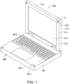
- FIG. 1 shows a schematic diagram of an electronic device in a state of use according to a first embodiment.
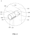
- FIG. 2 shows an enlarged partial perspective diagram of a circled portion 2 in FIG. 1 .
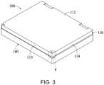
- FIG. 3 shows a schematic diagram of the electronic device in a stored state according to the first embodiment.
- FIG. 4 shows an enlarged partial perspective diagram of a circled portion 4 in FIG. 3 .
- FIG. 5 shows a schematic diagram of a positioning column and an operating member at a first position according to the first embodiment.
- FIG. 6 shows a schematic diagram of the positioning column and the operating member at a second position according to the first embodiment.
- an electronic device 100 includes a casing 110, a positioning column 130 and an operating member 150.
- the electronic device is, for example, a laptop computer.
- the electronic device is, for example but not limited to, a tablet computer or a keyboard deck.
- the casing 110 includes a first side surface 111 and a second side surface 112 arranged parallel to each other.
- the positioning column 130 passes through the casing 110 from the first side surface 111 and includes a first end portion 131 and a second end portion 132.
- the first end portion 131 movably protrudes from the first side surface 111.
- the operating member 150 is assembled on the casing 110 and corresponds to the positioning column 130.
- the operating member 150 includes a push portion 151 which presses against the second end portion 132 of the positioning column 130.
- the first end portion 131 of the positioning column 130 is accommodated in the casing 110.
- the push portion 151 presses against the second end portion 132, such that the first end portion 131 of the positioning column 130 protrudes from the first side surface 111 of the casing 110.
- the first position refers to a stored state of the positioning column 130 (as the details shown in FIG. 1 and FIG. 2 ), that is, the positioning column 130 is stored in the casing 110.
- the first end portion 131 of the positioning column 130 can be accommodated in the casing 110, so as to prevent the first end portion 131 from protruding from the casing 110 and causing issues such as collisions of the first end portion 131 or scratching of other objects by the first end portion 131.
- a second position refers to a state of use of the positioning column 130, that is, the positioning column 130 protrudes from the casing 110.
- the positioning column 130 can be pushed by the push portion 151 of the operating member 150 to have the first end portion 131 of the positioning column 130 protrude from the first side surface 111 of the casing 110, so as to provide the electronic device 100 with impact resistant effects.
- the first end portion 131 of the positioning column 130 can selectively protrude from the first side surface 111 of the casing 110.
- the positioning column 130 protruding from the first side surface 111 can press against a base 180, preventing direct large-area impact between the casing 110 and the base 180 and hence achieving protection effects of being impact resistant.
- the positioning column 130 is in the stored state, the positioning column 130 is withdrawn into the casing 110 to as to prevent the positioning column 130 from being collided or scratching other objects.
- impact resistant effects of the electronic device can be maintained while the protruding column structure is prevented from damage.
- the second end portion 132 has a first plane 1321 and a first convex portion 1322
- the push portion 151 has a second plane 1511 and a second convex portion 1512.
- the second convex portion 1512 correspondingly presses against the first convex portion 1322, such that the first end portion 131 of the positioning column 130 protrudes from the first side surface 111 of the casing 110.
- the positioning column 130 receives a force of action and is selectively accommodated in the casing 110 or protrudes from the first side surface 111 of the casing 110.
- the user toggles the operating member 150 from the second side surface 112 by a finger to change the operating member 150 from the first position ( FIG. 7 ) to the second position ( FIG. 3 ), such that the push portion 151 presses against the positioning column 130, and the first end portion 131 of the positioning column 130 then protrudes from the first side surface 111 of the casing 110 from the casing 110.
- the second convex portion 1512 of the push portion 151 moves or turns relative to the positioning column 130 along a toggle direction. More specifically, during the movement of the second convex portion 1512 to the corresponding first convex portion 1322, because the second convex portion 1512 moves along an inclined surface of the first convex portion 1322, the second convex portion 1512 gradually pushes the first convex portion 1322 so as to cause the first end portion 131 of the positioning column 130 to protrude from the first side surface 111 of the casing 110.
- the user again toggles the operating member 150 from the second side surface 112 by a finger to change the operating member 150 from the second position to the first position, thus releasing the pressing of the push portion 151 against the positioning column 130, so that user can push the positioning column 130 from the first side surface 111 into the casing 110 by a finger.
- the operating member 150 is electrically connected to a control device of the electronic device 100.
- a user can control, through a physical button on the electronic device 100 or a virtual button on a display surface, the operating member 150 to move between the first position and the second position, so as to have the positioning column 130 selectively be accommodated in the casing 110 or protrude from the first side surface 111 of the casing 110.
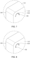
- FIG. 7 shows a schematic diagram of the operating member in FIG. 4 at the first position from another angle.
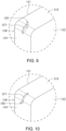
- FIG. 8 shows a schematic diagram of the operating member in FIG. 7 at the second position.
- the operating member 150 further includes a control member 152 which is exposed from the casing 110.
- the control member 152 is, for example, a rod-like object for the user to easily hold so as to toggle the operating member 150.
- the casing 110 further includes a passage 1121.
- the passage 1121 is provided on the second side surface 112, and the control member 152 is exposed from the passage 1121 of the casing 110.
- the control member 152 is movable along the channel 1121 to alter the operating member 150 between the first position and the second position.
- the user holds the control member 152 from the second side surface 112, moves the control member 152 along the passage 1121 and toggles the operating member 150, so as to move the operating member 150 from the first position in FIG. 5 and FIG. 7 to the second position in FIG. 6 and FIG. 8 .
- the user can toggle the operating member 150 from the second side surface 112 by a finger to alter the operating member 150 between the first position ( FIG. 7 ) and the second position ( FIG. 8 ).
- the electronic device 100 further includes an elastic member 170.
- the elastic member 170 is connected to the positioning column 130 and the operating member 150, so as to enable the positioning column 130 to be more stably accommodated in the casing 110 under an influence of elastic force.
- the user toggles the operating member 150 from the second side surface 112 by a finger to change the operating member 150 from the first position to the second position. Since the second convex portion 1512 presses against the first convex portion 1322, the first end portion 131 of the positioning column 130 overcomes the elastic force and protrudes from the first side surface 111 of the casing 110.
- the user toggles the operating member 150 from the second side surface 112 by a finger to change the operating member 150 from the second position to the first position. Since the second convex portion 1512 no longer presses against the first convex portion 1322, the positioning column 130 is withdrawn into the casing 110 under the influence of the elastic force, thus eliminating the step of pushing the positioning column 130 back into the casing 110 by a finger of the user.
- the positioning column 130 has a guide portion 133
- the casing 110 has an escort portion 115 facing the guide portion 133, such that the positioning column 130 moves along the escort portion 115 to protrude from the first side surface 111 or be accommodated in the casing 110.
- the casing 110 further includes a third side surface 113 and a fourth side surface 114 connected to each other. Two opposite sides of the third side surface 113 are connected to the first side surface 111 and the second side surface 112, respectively. Two opposite sides of the fourth side surface 114 are connected to the first side surface 111 and the second side surface 112, respectively.
- the positioning column 130 is adjacent to a junction of the third side surface 113 and the fourth side surface 114.
- the electronic device 100 further includes the base 180.
- the base 180 pivots at and faces the casing 110.
- the base 180 includes a fifth side surface 181 and a sixth side surface 182 parallel to each other, and a positioning slot 1811.
- the positioning slot 1811 is located on the fifth side surface 181.
- the positioning slot 1811 is for accommodating the first end portion 131.
- the torsion resistance between the casing 110 and the base 180 is increased.
- the casing 110 has a display surface 116 located on the first side surface 111 or the second side surface 112
- the base 180 has an input unit 1812 located on the fifth side surface 181.
- the display surface 116 is located on the first side surface 111
- the input unit 1812 is, for example, a keyboard or a touch pad and is located on the fifth side surface 181.
- the positioning column 130 is located outside the display surface 116 of the first side surface 111 and is adjacent to a junction of the third side surface 113 and the fourth side surface 114.
- FIG. 9 shows a schematic diagram of an operating member at a first position according to a second embodiment.
- FIG. 10 shows a schematic diagram of the operating member at a second position according to the second embodiment. Details of structures of the second embodiment similar to those of the first embodiment are omitted herein.
- the casing 110 further includes a third side surface 113, a fourth side surface 114 and a passage 117.
- the third side surface 113 is connected to the fourth side surface 114.
- Two opposite sides of the third side surface 113 are connected to the first side surface 111 and the second side surface 112, respectively.
- the passage 117 is provided from the third side surface 113 to the fourth side surface 114.
- the control member 152 is exposed from the passage 117. More specifically, the passage 117 extends from the third side surface 113 to the fourth side surface 114, and the control member 152 is movable between the third side surface 113 and the fourth side surface 114 along the passage 117.
- the user holds the control member 152 from the third side surface 113, and moves the control member 152 along the passage 117 to drive the operating member 150, so as to move the operating member 150 from the first position in FIG. 9 to the second position in FIG. 10 .
- the control member 152 is provided on the passage 117 at the third side surface 113 and the fourth side surface 114, such that the user is allowed to more directly observe the control member 152 and to more conveniently perform the operation.
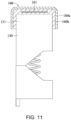
- FIG. 11 shows a schematic diagram of a positioning column according to a third embodiment.
- the electronic device 100 further includes a protective member 160 which envelopes the first end portion 131 of the positioning column 130.
- the protective member 160 has an outer layer 160a and an inner layer 160b.
- the outer layer 160a is made of a high hardness rubber
- the inner layer 160b is made of a high damping rubber.
- the protective member enveloping the positioning column is implemented in various forms, with details of other implementation forms to be described shortly.
- the protective member 160 includes a magnetic member 161, the positioning column 130 is made of a magnetic metal material, and the magnetic member 161 provides a magnetic attraction force to attract the protective member 160 at the positioning column 130.
- the magnetic member 161 is, for example, a magnet.
- One or more magnets 161 are embedded in the protective member 160, such that the protective member 160 is attracted to and envelops the first end portion 131 of the positioning column 130, thereby enhancing anti-collision and protective effects of the positioning column 130.
- FIG. 12 shows a schematic diagram of a positioning column according to a fourth embodiment.
- FIG. 13 shows a sectional schematic diagram of the positioning column in FIG. 12 .
- the positioning column 130 includes a hollow portion 134
- a protective member 260 includes an extension projecting portion 261
- the extension projecting portion 261 is inserted in the hollow portion 134.
- the protective member 260 is formed as a column-like extension projecting portion 261. By packing and securing the column-like extension projecting portion 261 in the hollow portion 134 of the positioning column 130, the protective member 260 is enabled to envelop the first end portion 131 of the positioning column 130.
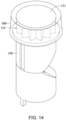
- FIG. 14 shows a partial perspective schematic diagram of a positioning column according to a fifth embodiment.
- the positioning column 130 is made of a metal material, and a protective member 360 is made of an elastic material.
- the positioning column130 includes an assembly portion 135 that is located at the first end portion 131, and the protective member 360 is formed by means of injection molding on the assembly portion 135.
- the assembly portion 135 surrounds a side surface of the first end portion 131, and a surface of the protective member 360 protrudes from a surface of the first end portion 131 of the positioning column 130.
- the protective member 360 is, for example, made of plastic, rubber or silicone.
- the assembly portion 135 has a serrated structure, and the protective member 360 for corresponding engagement is directly formed on the assembly portion 135 of the positioning column 130 so as to provide mutual engagement.
- the assembly portion 135 is, for example but not limited to, a serrated structure, and any shape capable of achieving an engagement structure can be used.
- a surface of the protective member 360 slightly protrudes from a surface of the first end portion 131 of the positioning column 130, so as to prevent the first end portion 131 of the positioning column 130 from directly coming into contact with the base 180, an external device or a user, hence protecting the positioning column 130 and providing buffering effects.
- the first end portion 131 of the positioning column 130 can selectively protrude from the first side surface 111 of the casing 110.
- the positioning column 130 protruding from the first side surface 111 can press against the base 180, preventing direct large-area impact between the casing 110 and the base 180 and hence achieving protection effects of being impact resistant.
- the positioning column 130 is withdrawn into the casing 110 to as to prevent the positioning column 130 from being collided or scratching other objects.
- impact resistant effects of the electronic device 100 can be maintained while the protruding column structure is prevented from damage.
Landscapes
- Engineering & Computer Science (AREA)
- Computer Hardware Design (AREA)
- Theoretical Computer Science (AREA)
- Physics & Mathematics (AREA)
- Human Computer Interaction (AREA)
- General Engineering & Computer Science (AREA)
- General Physics & Mathematics (AREA)
- Mathematical Physics (AREA)
- Casings For Electric Apparatus (AREA)
- Surgical Instruments (AREA)
- Valve Device For Special Equipments (AREA)
- Noodles (AREA)
Abstract

Description
- The present application relates to an electronic device, and more particularly to a portable electronic device.
- A common portable electronic device such as a laptop computer is provided with an impact resistant structure between a screen device and an input device. Thus, when the laptop computer is closed, impact between the screen device and the input device is reduced. Moreover, torque received between the screen device and the input device when the laptop computer falls down is also reduced.
- However, since the impact resistant structure is a structure that protrudes from a casing, issues such as scratching or collisions are more likely to occur during the use of the laptop computer. For example, an impact resistance structure in a form of a protruding column can be broken due to collisions over an extended period of time.
- In view of the above issues, an electronic device provided according to an embodiment includes a casing, a positioning column and an operating member. The casing includes a first side surface and a second side surface arranged parallel to each other. The positioning column passes through the casing from the first side surface and includes a first end portion and a second end portion. The first end portion movably protrudes from the first side surface, and the second end portion has a first plane and a first convex portion. The operating member is assembled on the casing and corresponds to the positioning column. The operating member includes a push portion. The push portion presses against the second end portion of the positioning column and has a second plane and a second convex portion. When the operating member is located at a first position, the first convex portion correspondingly presses against the second plane, the second convex portion correspondingly presses against the first plane, and the first end portion of the positioning column is accommodated in the casing. When the operating member is located at a second position, the first convex portion correspondingly presses against the second convex portion, and the first end portion of the positioning column protrudes from the first side surface of the casing.
- In some embodiments, the positioning column has a guide portion, and the casing has an escort portion corresponding to the guide portion.
- In some embodiments, the operating member further includes a control member which is exposed from the casing.
- In some embodiments, the casing further includes a passage. The passage is provided on the second side surface, and the control member is exposed from the passage of the casing.
- In some embodiments, the casing further includes a third side surface, a fourth side surface and a passage. The third side surface is connected to the fourth side surface. Two opposite sides of the third side surface are connected to the first side surface and the second side surface, respectively. Two opposite sides of the fourth side surface are connected to the first side surface and the second side surface, respectively. The passage is provided from the third side surface to the fourth side surface. The control member is exposed from the passage.
- In some embodiments, an elastic member is further included. The elastic member is connected to the positioning column and the operating member.
- In some embodiments, a protective member enveloping the first end portion of the positioning column is further included.
- In some embodiments, the protective member includes a magnetic member, the positioning column is made of a magnetic metal material, and the magnetic member provides a magnetic attraction force to attract the protective member at the positioning column.
- In some embodiments, the positioning column includes a hollow portion, and the protective member includes an extension projecting portion which is inserted in the hollow portion.
- In some embodiments, the positioning column is made of a metal material, and the protective member is made of an elastic material. The positioning column includes an assembly portion that is located at the first end portion, and the protective member is formed by means of injection molding on the assembly portion.
- In some embodiments, the assembly portion surrounds a side surface of the first end portion, and a surface of the protective member protrudes from a surface of the first end portion of the positioning column.
- In some embodiments, the protective member has an outer layer and an inner layer. The outer layer is formed by high hardness rubber, and the inner layer is formed by high damping rubber.
- In some embodiments, a base is further included. The base faces the casing, and includes a fifth side surface and a sixth surface parallel to each other and a positioning slot. The positioning slot is located at the fifth side surface, and the positioning slot is for accommodating the first end portion when the first end portion of the positioning column protrudes from the first side surface of the casing.
- In some embodiments, the casing has a display surface located on the first side surface or the second side surface, and the base has an input unit located on the fifth side surface.
- An electronic device provided according to another embodiment includes a casing, a positioning column and an operating member. The casing includes a first side surface and a second side surface arranged parallel to each other. The positioning column passes through the casing from the first side surface and includes a first end portion and a second end portion. The first end portion movably protrudes from the first side surface. The operating member is assembled on the casing and corresponds to the positioning column. The operating member includes a push portion, which presses against the second end portion of the positioning column. When the operating member is located at a first position, the first end portion of the positioning column is accommodated in the casing. When the operating member is located at a second position, the first end portion of the positioning column protrudes from the first side surface of the casing.
- In conclusion, in the electronic device provided according to the above embodiments of the present invention, the first end portion of the positioning column can selectively protrude from the first side surface of the casing through the push portion of the operating member. Thus, when the positioning column is in a state of use, the positioning column protrudes from the first side surface so as to achieve protection effects of being impact resistant. When the positioning column is in a stored state, the positioning column is withdrawn into the casing to as to prevent the positioning column from being collidedor scratching other objects. Thus, impact resistance effects of the electronic device can be maintained while the protruding column structure is prevented from damage.
-
-
FIG. 1 is a schematic diagram of an electronic device in a state of use according to a first embodiment. -
FIG. 2 is an enlarged partial perspective diagram of a circledportion 2 inFIG. 1 . -
FIG. 3 is a schematic diagram of the electronic device in a stored state according to the first embodiment. -
FIG. 4 is an enlarged partial perspective diagram of a circledportion 4 inFIG. 3 . -
FIG. 5 is a schematic diagram of a positioning column and an operating member at a first position according to the first embodiment. -
FIG. 6 is a schematic diagram of the positioning column and the operating member at a second position according to the first embodiment. -
FIG. 7 is a schematic diagram of the operating member inFIG. 4 at the first position from another angle. -
FIG. 8 is a schematic diagram of the operating member inFIG. 7 at the second position. -
FIG. 9 is a schematic diagram of an operating member at a first position according to a second embodiment. -
FIG. 10 is a schematic diagram of the operating member at a second position according to the second embodiment. -
FIG. 11 is a schematic diagram of a positioning column according to a third embodiment. -
FIG. 12 is a schematic diagram of a positioning column according to a fourth embodiment. -
FIG. 13 is a sectional schematic diagram of the positioning column inFIG. 12 . -
FIG. 14 is a partial perspective schematic diagram of a positioning column according to a fifth embodiment. - Refer to
FIG. 1 to FIG. 6 .FIG. 1 shows a schematic diagram of an electronic device in a state of use according to a first embodiment.FIG. 2 shows an enlarged partial perspective diagram of a circledportion 2 inFIG. 1 .FIG. 3 shows a schematic diagram of the electronic device in a stored state according to the first embodiment.FIG. 4 shows an enlarged partial perspective diagram of a circledportion 4 inFIG. 3 .FIG. 5 shows a schematic diagram of a positioning column and an operating member at a first position according to the first embodiment.FIG. 6 shows a schematic diagram of the positioning column and the operating member at a second position according to the first embodiment. As shown inFIG. 1 andFIG. 2 , anelectronic device 100 includes acasing 110, apositioning column 130 and an operatingmember 150. In a first embodiment, the electronic device is, for example, a laptop computer. In other embodiments, the electronic device is, for example but not limited to, a tablet computer or a keyboard deck. - As shown in
FIG. 1 to FIG. 6 , thecasing 110 includes afirst side surface 111 and asecond side surface 112 arranged parallel to each other. Thepositioning column 130 passes through thecasing 110 from thefirst side surface 111 and includes afirst end portion 131 and asecond end portion 132. Thefirst end portion 131 movably protrudes from thefirst side surface 111. - The operating
member 150 is assembled on thecasing 110 and corresponds to thepositioning column 130. The operatingmember 150 includes apush portion 151 which presses against thesecond end portion 132 of thepositioning column 130. - As shown in
FIG. 5 , when the operatingmember 150 is located at a first position, thefirst end portion 131 of thepositioning column 130 is accommodated in thecasing 110. As shown inFIG. 6 , when the operatingmember 150 is located at a second position in response to a rotation operation, thepush portion 151 presses against thesecond end portion 132, such that thefirst end portion 131 of thepositioning column 130 protrudes from thefirst side surface 111 of thecasing 110. - In the first embodiments, as shown in
FIG. 1 to FIG. 6 , the first position refers to a stored state of the positioning column 130 (as the details shown inFIG. 1 andFIG. 2 ), that is, thepositioning column 130 is stored in thecasing 110. When a user is currently using theelectronic device 100 or theelectronic device 100 is in an open state, thefirst end portion 131 of thepositioning column 130 can be accommodated in thecasing 110, so as to prevent thefirst end portion 131 from protruding from thecasing 110 and causing issues such as collisions of thefirst end portion 131 or scratching of other objects by thefirst end portion 131. As shown inFIG. 3 andFIG. 4 , a second position refers to a state of use of thepositioning column 130, that is, thepositioning column 130 protrudes from thecasing 110. When the user is to close theelectronic device 100 or theelectronic device 100 is in a closed state, thepositioning column 130 can be pushed by thepush portion 151 of the operatingmember 150 to have thefirst end portion 131 of thepositioning column 130 protrude from thefirst side surface 111 of thecasing 110, so as to provide theelectronic device 100 with impact resistant effects. - More specifically, with the
push portion 151 of the operatingmember 150, thefirst end portion 131 of thepositioning column 130 can selectively protrude from thefirst side surface 111 of thecasing 110. When thepositioning column 130 is in the state of use, thepositioning column 130 protruding from thefirst side surface 111 can press against abase 180, preventing direct large-area impact between thecasing 110 and thebase 180 and hence achieving protection effects of being impact resistant. When thepositioning column 130 is in the stored state, thepositioning column 130 is withdrawn into thecasing 110 to as to prevent thepositioning column 130 from being collided or scratching other objects. Thus, impact resistant effects of the electronic device can be maintained while the protruding column structure is prevented from damage. - In the first embodiment, the
second end portion 132 has afirst plane 1321 and a firstconvex portion 1322, and thepush portion 151 has asecond plane 1511 and a secondconvex portion 1512. Referring toFIG. 5 and FIG. 6 again, when the operatingmember 150 is located at the first position, the firstconvex portion 1322 correspondingly presses against thesecond plane 1511, the secondconvex portion 1512 correspondingly presses against thefirst plane 1321, and thefirst end portion 131 of thepositioning column 130 is accommodated in thecasing 110. When the operatingmember 150 is located at the second position in response to a rotation operation, the secondconvex portion 1512 correspondingly presses against the firstconvex portion 1322, such that thefirst end portion 131 of thepositioning column 130 protrudes from thefirst side surface 111 of thecasing 110. - In the first embodiment, the
positioning column 130 receives a force of action and is selectively accommodated in thecasing 110 or protrudes from thefirst side surface 111 of thecasing 110. For example, as shown inFIG. 7 and FIG. 8 , when thepositioning column 130 is to be in the state of use, the user toggles the operatingmember 150 from thesecond side surface 112 by a finger to change the operatingmember 150 from the first position (FIG. 7 ) to the second position (FIG. 3 ), such that thepush portion 151 presses against thepositioning column 130, and thefirst end portion 131 of thepositioning column 130 then protrudes from thefirst side surface 111 of thecasing 110 from thecasing 110. As shown inFIG. 5 and FIG. 6 , when the user toggles the operatingmember 150, the secondconvex portion 1512 of thepush portion 151 moves or turns relative to thepositioning column 130 along a toggle direction. More specifically, during the movement of the secondconvex portion 1512 to the corresponding firstconvex portion 1322, because the secondconvex portion 1512 moves along an inclined surface of the firstconvex portion 1322, the secondconvex portion 1512 gradually pushes the firstconvex portion 1322 so as to cause thefirst end portion 131 of thepositioning column 130 to protrude from thefirst side surface 111 of thecasing 110. When thepositioning column 130 is to be in the stored state, the user again toggles the operatingmember 150 from thesecond side surface 112 by a finger to change the operatingmember 150 from the second position to the first position, thus releasing the pressing of thepush portion 151 against thepositioning column 130, so that user can push thepositioning column 130 from thefirst side surface 111 into thecasing 110 by a finger. For another example, in other embodiments, the operatingmember 150 is electrically connected to a control device of theelectronic device 100. A user can control, through a physical button on theelectronic device 100 or a virtual button on a display surface, the operatingmember 150 to move between the first position and the second position, so as to have thepositioning column 130 selectively be accommodated in thecasing 110 or protrude from thefirst side surface 111 of thecasing 110. - Refer to
FIG. 7 and FIG. 8 as well asFIG. 5 and FIG. 6 .FIG. 7 shows a schematic diagram of the operating member inFIG. 4 at the first position from another angle.FIG. 8 shows a schematic diagram of the operating member inFIG. 7 at the second position. As shown inFIG. 5 to FIG. 8 , in the first embodiment, the operatingmember 150 further includes acontrol member 152 which is exposed from thecasing 110. Thecontrol member 152 is, for example, a rod-like object for the user to easily hold so as to toggle the operatingmember 150. As shown inFIG. 7 and FIG. 8 , thecasing 110 further includes apassage 1121. Thepassage 1121 is provided on thesecond side surface 112, and thecontrol member 152 is exposed from thepassage 1121 of thecasing 110. In the first embodiment, thecontrol member 152 is movable along thechannel 1121 to alter the operatingmember 150 between the first position and the second position. For example, the user holds thecontrol member 152 from thesecond side surface 112, moves thecontrol member 152 along thepassage 1121 and toggles the operatingmember 150, so as to move the operatingmember 150 from the first position inFIG. 5 andFIG. 7 to the second position inFIG. 6 andFIG. 8 . As such, the user can toggle the operatingmember 150 from thesecond side surface 112 by a finger to alter the operatingmember 150 between the first position (FIG. 7 ) and the second position (FIG. 8 ). - Referring to
FIG. 5 and FIG. 6 again, in the first embodiment, theelectronic device 100 further includes anelastic member 170. Theelastic member 170 is connected to thepositioning column 130 and the operatingmember 150, so as to enable thepositioning column 130 to be more stably accommodated in thecasing 110 under an influence of elastic force. When thepositioning column 130 is to be in the state of use, the user toggles the operatingmember 150 from thesecond side surface 112 by a finger to change the operatingmember 150 from the first position to the second position. Since the secondconvex portion 1512 presses against the firstconvex portion 1322, thefirst end portion 131 of thepositioning column 130 overcomes the elastic force and protrudes from thefirst side surface 111 of thecasing 110. When thepositioning column 130 is to be in the stored state, the user toggles the operatingmember 150 from thesecond side surface 112 by a finger to change the operatingmember 150 from the second position to the first position. Since the secondconvex portion 1512 no longer presses against the firstconvex portion 1322, thepositioning column 130 is withdrawn into thecasing 110 under the influence of the elastic force, thus eliminating the step of pushing thepositioning column 130 back into thecasing 110 by a finger of the user. - Referring to
FIG. 2 again, in the first embodiment, thepositioning column 130 has aguide portion 133, and thecasing 110 has anescort portion 115 facing theguide portion 133, such that thepositioning column 130 moves along theescort portion 115 to protrude from thefirst side surface 111 or be accommodated in thecasing 110. - Referring to
FIG. 1 again,FIG. 2 andFIG. 3 , in the first embodiment, thecasing 110 further includes athird side surface 113 and afourth side surface 114 connected to each other. Two opposite sides of thethird side surface 113 are connected to thefirst side surface 111 and thesecond side surface 112, respectively. Two opposite sides of thefourth side surface 114 are connected to thefirst side surface 111 and thesecond side surface 112, respectively. Thepositioning column 130 is adjacent to a junction of thethird side surface 113 and thefourth side surface 114. Theelectronic device 100 further includes thebase 180. The base 180 pivots at and faces thecasing 110. Thebase 180 includes afifth side surface 181 and asixth side surface 182 parallel to each other, and apositioning slot 1811. Thepositioning slot 1811 is located on thefifth side surface 181. When thefirst end portion 131 of thepositioning column 130 protrudes from thefirst side surface 111 of thecasing 110, thepositioning slot 1811 is for accommodating thefirst end portion 131. Thus, the torsion resistance between thecasing 110 and thebase 180 is increased. When theelectronic device 100 falls down, a limiting effect is provided since thefirst end portion 131 is accommodated in thepositioning slot 1811, preventing a pivot between thecasing 110 and thebase 180 of theelectronic device 100 from damage caused by the impact of the falling. In the first embodiments, thecasing 110 has adisplay surface 116 located on thefirst side surface 111 or thesecond side surface 112, and thebase 180 has aninput unit 1812 located on thefifth side surface 181. Herein, thedisplay surface 116 is located on thefirst side surface 111, and theinput unit 1812 is, for example, a keyboard or a touch pad and is located on thefifth side surface 181. Further, thepositioning column 130 is located outside thedisplay surface 116 of thefirst side surface 111 and is adjacent to a junction of thethird side surface 113 and thefourth side surface 114. - Refer to
FIG. 9 to FIG. 10. FIG. 9 shows a schematic diagram of an operating member at a first position according to a second embodiment.FIG. 10 shows a schematic diagram of the operating member at a second position according to the second embodiment. Details of structures of the second embodiment similar to those of the first embodiment are omitted herein. This embodiment differs from the first embodiment in that the passage and the control member have different implementation forms. In the second embodiment, thecasing 110 further includes athird side surface 113, afourth side surface 114 and apassage 117. Thethird side surface 113 is connected to thefourth side surface 114. Two opposite sides of thethird side surface 113 are connected to thefirst side surface 111 and thesecond side surface 112, respectively. Thepassage 117 is provided from thethird side surface 113 to thefourth side surface 114. Thecontrol member 152 is exposed from thepassage 117. More specifically, thepassage 117 extends from thethird side surface 113 to thefourth side surface 114, and thecontrol member 152 is movable between thethird side surface 113 and thefourth side surface 114 along thepassage 117. For example, the user holds thecontrol member 152 from thethird side surface 113, and moves thecontrol member 152 along thepassage 117 to drive the operatingmember 150, so as to move the operatingmember 150 from the first position inFIG. 9 to the second position inFIG. 10 . As such, thecontrol member 152 is provided on thepassage 117 at thethird side surface 113 and thefourth side surface 114, such that the user is allowed to more directly observe thecontrol member 152 and to more conveniently perform the operation. - Refer to
FIG. 11. FIG. 11 shows a schematic diagram of a positioning column according to a third embodiment. In the third embodiment, theelectronic device 100 further includes aprotective member 160 which envelopes thefirst end portion 131 of thepositioning column 130. Theprotective member 160 has anouter layer 160a and aninner layer 160b. Theouter layer 160a is made of a high hardness rubber, and theinner layer 160b is made of a high damping rubber. The protective member enveloping the positioning column is implemented in various forms, with details of other implementation forms to be described shortly. As shown inFIG. 11 , in the third embodiment, theprotective member 160 includes amagnetic member 161, thepositioning column 130 is made of a magnetic metal material, and themagnetic member 161 provides a magnetic attraction force to attract theprotective member 160 at thepositioning column 130. In the third embodiment, themagnetic member 161 is, for example, a magnet. One ormore magnets 161 are embedded in theprotective member 160, such that theprotective member 160 is attracted to and envelops thefirst end portion 131 of thepositioning column 130, thereby enhancing anti-collision and protective effects of thepositioning column 130. - Refer to
FIG. 12 to FIG. 13 .FIG. 12 shows a schematic diagram of a positioning column according to a fourth embodiment.FIG. 13 shows a sectional schematic diagram of the positioning column inFIG. 12 . Regarding other implementation forms of the protective member enveloping the positioning column, similar structural details of the protective member are omitted herein. In the fourth embodiment, as shown inFIG. 12 andFIG. 13 , thepositioning column 130 includes ahollow portion 134, aprotective member 260 includes anextension projecting portion 261, and theextension projecting portion 261 is inserted in thehollow portion 134. In the fourth embodiment, theprotective member 260 is formed as a column-likeextension projecting portion 261. By packing and securing the column-likeextension projecting portion 261 in thehollow portion 134 of thepositioning column 130, theprotective member 260 is enabled to envelop thefirst end portion 131 of thepositioning column 130. - Refer to
FIG. 14. FIG. 14 shows a partial perspective schematic diagram of a positioning column according to a fifth embodiment. Regarding other implementation forms of the protective element enveloping the positioning column, in the fifth embodiment, as shown inFIG. 14 , thepositioning column 130 is made of a metal material, and aprotective member 360 is made of an elastic material. The positioning column130 includes an assembly portion 135 that is located at thefirst end portion 131, and theprotective member 360 is formed by means of injection molding on the assembly portion 135. The assembly portion 135 surrounds a side surface of thefirst end portion 131, and a surface of theprotective member 360 protrudes from a surface of thefirst end portion 131 of thepositioning column 130. In the fifth embodiment, theprotective member 360 is, for example, made of plastic, rubber or silicone. In the fifth embodiment, the assembly portion 135 has a serrated structure, and theprotective member 360 for corresponding engagement is directly formed on the assembly portion 135 of thepositioning column 130 so as to provide mutual engagement. In the fifth embodiment, the assembly portion 135 is, for example but not limited to, a serrated structure, and any shape capable of achieving an engagement structure can be used. Moreover, a surface of theprotective member 360 slightly protrudes from a surface of thefirst end portion 131 of thepositioning column 130, so as to prevent thefirst end portion 131 of thepositioning column 130 from directly coming into contact with thebase 180, an external device or a user, hence protecting thepositioning column 130 and providing buffering effects. - In conclusion, in the
electronic device 100 provided according to above embodiments, with thepush portion 151 of the operatingmember 150, thefirst end portion 131 of thepositioning column 130 can selectively protrude from thefirst side surface 111 of thecasing 110. When thepositioning column 130 is in the state of use, thepositioning column 130 protruding from thefirst side surface 111 can press against thebase 180, preventing direct large-area impact between thecasing 110 and thebase 180 and hence achieving protection effects of being impact resistant. When thepositioning column 130 is in the stored state, thepositioning column 130 is withdrawn into thecasing 110 to as to prevent thepositioning column 130 from being collided or scratching other objects. Thus, impact resistant effects of theelectronic device 100 can be maintained while the protruding column structure is prevented from damage.
Claims (15)
- An electronic device, comprising:a casing comprising a first side surface and a second side surface arranged parallel to each other;a positioning column passing through the casing from the first side surface, the positioning comprising a first end portion and a second end portion, and the first end portion movably protruding from the first side surface; andan operating member, assembled on the casing and corresponding to the positioning column, the operating member comprising a push portion, and the push portion pressing against the second end portion of the positioning column;wherein, when the operating member is located at a first position, the first end portion of the positioning column is accommodated in the casing; when the operating member is located at a second position, the first end portion of the positioning column protrudes from the first side surface of the casing.
- The electronic device according to claim 1, wherein the second end has a first plane and a first convex portion, the push portion has a second plane and a second convex portion;
wherein when the operating member is located at the first position, the first convex portion correspondingly presses against the second plane, and the second convex portion corresponding presses against the first plane; when the operating member is located at the second position, the second convex portion correspondingly presses against the first convex portion. - The electronic device according to claim 1 or claim 2, wherein the positioning column has a guide portion, and the casing has an escort portion corresponding to the guide portion.
- The electronic device according to claim 3, wherein the operating member further comprises a control member exposed from the casing.
- The electronic device according to claim 4, wherein the casing further comprises a passage provided on the second side surface, and the control member is exposed from the passage of the casing.
- The electronic device according to claim 4, wherein the casing further comprises a third side surface, a fourth side surface and a passage; the third side surface is connected to the fourth side surface, two opposite sides of the third side surface are connected to the first side surface and the second side surface, respectively, and two opposite sides of the fourth side surface are connected to the first side surface and the second side surface, respectively; and the passage is provided from the third side surface to the fourth side surface, and the control member is exposed from the passage.
- The electronic device according to claim 1 or claim 2, further comprising:
an elastic member connected to the positioning column and the operating member. - The electronic device according to claim 1 or claim 2, further comprising:
a protective member enveloping the first end position of the positioning column. - The electronic device according to claim 8, wherein the protective member comprises a magnetic member, the positioning column is made of a magnetic metal material, and the magnetic member provides a magnetic attraction force to attract the protective member at the positioning column.
- The electronic device according to claim 8, wherein the positioning column comprises a hollow portion, and the protective member comprises an extension projecting portion which is inserted in the hollow portion.
- The electronic device according to claim 8, wherein the positioning column is made of a metal material, the protective member is made of an elastic material, the positioning column comprises an assembly portion that is located on the first end portion, and the protective member is formed by means of injection molding on the assembly portion.
- The electronic device according to claim 11, wherein the assembly portion surrounds a side surface of the first end portion, and a surface of the protective member protrudes from a surface of the first end portion of the positioning column.
- The electronic device according to claim 8, wherein the protective member has an outer layer and an inner layer, the outer layer is formed by high hardness rubber, and the inner layer is formed by high damping rubber.
- The electronic device according to claim 1 or claim 2, further comprising: a base facing the casing, and the base comprising a fifth side surface and a sixth surface parallel to each other and a positioning slot; the positioning slot located at the fifth side surface, and the positioning slot accommodating the first end portion when the first end portion of the positioning column protrudes from the first side surface of the casing.
- The electronic device according to claim 14, wherein the casing has a display surface located on the first side surface or the second side surface, and the base has an input unit located on the fifth side surface.
Applications Claiming Priority (2)
| Application Number | Priority Date | Filing Date | Title |
|---|---|---|---|
| US202263309470P | 2022-02-11 | 2022-02-11 | |
| CN202210994622.5A CN116627209A (en) | 2022-02-11 | 2022-08-18 | Electronic device |
Publications (2)
| Publication Number | Publication Date |
|---|---|
| EP4227763A1 true EP4227763A1 (en) | 2023-08-16 |
| EP4227763B1 EP4227763B1 (en) | 2025-12-17 |
Family
ID=84361743
Family Applications (1)
| Application Number | Title | Priority Date | Filing Date |
|---|---|---|---|
| EP22209072.2A Active EP4227763B1 (en) | 2022-02-11 | 2022-11-23 | Electronic device |
Country Status (4)
| Country | Link |
|---|---|
| US (1) | US12353252B2 (en) |
| EP (1) | EP4227763B1 (en) |
| AU (1) | AU2022279476B2 (en) |
| TW (2) | TWI815698B (en) |
Cited By (1)
| Publication number | Priority date | Publication date | Assignee | Title |
|---|---|---|---|---|
| EP4542334A4 (en) * | 2023-08-28 | 2025-04-30 | Samsung Electronics Co., Ltd. | ELECTRONIC DEVICE INCLUDING A PROTECTIVE COVER FOR PROTECTING A SCREEN |
Citations (1)
| Publication number | Priority date | Publication date | Assignee | Title |
|---|---|---|---|---|
| US20130250501A1 (en) * | 2012-03-20 | 2013-09-26 | Hon Hai Precision Industry Co., Ltd. | Folding electronic device with retracting locking mechanism |
Family Cites Families (17)
| Publication number | Priority date | Publication date | Assignee | Title |
|---|---|---|---|---|
| TW384655U (en) | 1999-05-17 | 2000-03-11 | Guo Yu Huan | Improved structure for the foot pad of furniture |
| CN2763868Y (en) * | 2004-12-11 | 2006-03-08 | 鸿富锦精密工业(深圳)有限公司 | Lock for cover of notebook computer |
| US20060133019A1 (en) * | 2004-12-21 | 2006-06-22 | Fuminori Yamazaki | Latch assembly for an electronic device |
| EP1876507B1 (en) * | 2005-04-27 | 2012-01-11 | Fujitsu Ltd. | Function enhancement unit for electronic device |
| TWI314678B (en) * | 2006-05-19 | 2009-09-11 | Hon Hai Prec Ind Co Ltd | Connecting device and docking station with the same |
| US7609514B2 (en) * | 2007-04-11 | 2009-10-27 | Hewlett-Packard Development Company, L.P. | Electronic device locking system |
| TWM322013U (en) * | 2007-04-30 | 2007-11-11 | Wistron Corp | Open/close position limiting mechanism and lifting type electronic device comprising the same |
| TWI381795B (en) * | 2008-10-08 | 2013-01-01 | Compal Electronics Inc | Latching structure of an mobile electronic device |
| TWI416303B (en) * | 2009-01-09 | 2013-11-21 | Hon Hai Prec Ind Co Ltd | Electronic device |
| TWM380504U (en) * | 2009-11-25 | 2010-05-11 | Wistron Corp | Electronic device |
| CN105960130B (en) * | 2012-04-17 | 2018-10-26 | 青岛科而泰环境控制技术有限公司 | The impact resistance protective shell of portable electronics |
| TWI631285B (en) * | 2017-03-13 | 2018-08-01 | 緯創資通股份有限公司 | Unloading mechanism assembly |
| CN207497283U (en) | 2017-11-08 | 2018-06-15 | 李宇生 | A kind of screw and nut protection cap of built-in magnet |
| CN108445969B (en) | 2018-03-21 | 2021-04-13 | 联想(北京)有限公司 | Electronic equipment |
| CN210639543U (en) | 2019-11-28 | 2020-05-29 | 合肥联宝信息技术有限公司 | Foot pad mechanism and electronic equipment |
| JP2021111036A (en) * | 2020-01-08 | 2021-08-02 | レノボ・シンガポール・プライベート・リミテッド | Electronic device |
| CN214427873U (en) * | 2021-02-18 | 2021-10-19 | 纬联电子科技(中山)有限公司 | Electronic device and its fixed support assembly |
-
2022
- 2022-10-13 TW TW111138915A patent/TWI815698B/en active
- 2022-10-13 TW TW112121505A patent/TWI847753B/en active
- 2022-11-07 US US17/982,405 patent/US12353252B2/en active Active
- 2022-11-23 EP EP22209072.2A patent/EP4227763B1/en active Active
- 2022-11-30 AU AU2022279476A patent/AU2022279476B2/en active Active
Patent Citations (1)
| Publication number | Priority date | Publication date | Assignee | Title |
|---|---|---|---|---|
| US20130250501A1 (en) * | 2012-03-20 | 2013-09-26 | Hon Hai Precision Industry Co., Ltd. | Folding electronic device with retracting locking mechanism |
Cited By (1)
| Publication number | Priority date | Publication date | Assignee | Title |
|---|---|---|---|---|
| EP4542334A4 (en) * | 2023-08-28 | 2025-04-30 | Samsung Electronics Co., Ltd. | ELECTRONIC DEVICE INCLUDING A PROTECTIVE COVER FOR PROTECTING A SCREEN |
Also Published As
| Publication number | Publication date |
|---|---|
| US20230259176A1 (en) | 2023-08-17 |
| AU2022279476B2 (en) | 2024-06-06 |
| TWI815698B (en) | 2023-09-11 |
| TW202338558A (en) | 2023-10-01 |
| US12353252B2 (en) | 2025-07-08 |
| TW202333018A (en) | 2023-08-16 |
| TWI847753B (en) | 2024-07-01 |
| EP4227763B1 (en) | 2025-12-17 |
| AU2022279476A1 (en) | 2023-08-31 |
Similar Documents
| Publication | Publication Date | Title |
|---|---|---|
| US7515930B2 (en) | Electronic device sliding mechanism | |
| US9280178B2 (en) | Portable electronic apparatus and expanding platform thereof | |
| US8493742B2 (en) | Push-button switch assembly and electronic device with same | |
| US20090008163A1 (en) | Pen unit and electronic apparatus | |
| US20230068455A1 (en) | Bistable retractable buttons | |
| US12353252B2 (en) | Electronic device | |
| TW201804493A (en) | Keyswitch, keyboard and keyswitch manufacturing method thereof | |
| US9201463B2 (en) | Portable electronic device capable of lifting a host module as a display module rotates relative to the host module | |
| CN109065392B (en) | Key | |
| US11157046B2 (en) | Electronic device | |
| US10426239B2 (en) | Receiving device | |
| CN102692974B (en) | Electronic device with adjustable plate structure | |
| US8422211B2 (en) | Assembling/disassembling keyboard structure for a portable device | |
| WO2021227503A1 (en) | Card holder assembly, and mobile terminal comprising same | |
| CN212032923U (en) | Key structure and electronic equipment with same | |
| US6996834B2 (en) | Disk drive with ejection apparatus | |
| TWI699810B (en) | Key switch | |
| CN210691153U (en) | electronic device | |
| CN105020551A (en) | Device fixing structure and electronic device | |
| TWI533345B (en) | Button and its keyboard | |
| TWI382299B (en) | Push-push out position structure and portable electronic device using same | |
| CN107807711A (en) | supporting device of electronic device | |
| CN116627209A (en) | Electronic device | |
| CN216748744U (en) | An intelligent mathematical computing device | |
| CN101742864A (en) | Positioning mechanism |
Legal Events
| Date | Code | Title | Description |
|---|---|---|---|
| PUAI | Public reference made under article 153(3) epc to a published international application that has entered the european phase |
Free format text: ORIGINAL CODE: 0009012 |
|
| STAA | Information on the status of an ep patent application or granted ep patent |
Free format text: STATUS: THE APPLICATION HAS BEEN PUBLISHED |
|
| AK | Designated contracting states |
Kind code of ref document: A1 Designated state(s): AL AT BE BG CH CY CZ DE DK EE ES FI FR GB GR HR HU IE IS IT LI LT LU LV MC ME MK MT NL NO PL PT RO RS SE SI SK SM TR |
|
| STAA | Information on the status of an ep patent application or granted ep patent |
Free format text: STATUS: REQUEST FOR EXAMINATION WAS MADE |
|
| 17P | Request for examination filed |
Effective date: 20240109 |
|
| RBV | Designated contracting states (corrected) |
Designated state(s): AL AT BE BG CH CY CZ DE DK EE ES FI FR GB GR HR HU IE IS IT LI LT LU LV MC ME MK MT NL NO PL PT RO RS SE SI SK SM TR |
|
| STAA | Information on the status of an ep patent application or granted ep patent |
Free format text: STATUS: EXAMINATION IS IN PROGRESS |
|
| 17Q | First examination report despatched |
Effective date: 20250321 |
|
| GRAP | Despatch of communication of intention to grant a patent |
Free format text: ORIGINAL CODE: EPIDOSNIGR1 |
|
| STAA | Information on the status of an ep patent application or granted ep patent |
Free format text: STATUS: GRANT OF PATENT IS INTENDED |
|
| INTG | Intention to grant announced |
Effective date: 20250905 |
|
| GRAS | Grant fee paid |
Free format text: ORIGINAL CODE: EPIDOSNIGR3 |
|
| GRAA | (expected) grant |
Free format text: ORIGINAL CODE: 0009210 |
|
| STAA | Information on the status of an ep patent application or granted ep patent |
Free format text: STATUS: THE PATENT HAS BEEN GRANTED |
|
| AK | Designated contracting states |
Kind code of ref document: B1 Designated state(s): AL AT BE BG CH CY CZ DE DK EE ES FI FR GB GR HR HU IE IS IT LI LT LU LV MC ME MK MT NL NO PL PT RO RS SE SI SK SM TR |
|
| REG | Reference to a national code |
Ref country code: CH Ref legal event code: F10 Free format text: ST27 STATUS EVENT CODE: U-0-0-F10-F00 (AS PROVIDED BY THE NATIONAL OFFICE) Effective date: 20251217 Ref country code: GB Ref legal event code: FG4D |
|
| REG | Reference to a national code |
Ref country code: DE Ref legal event code: R096 Ref document number: 602022026949 Country of ref document: DE |
|
| REG | Reference to a national code |
Ref country code: LT Ref legal event code: MG9D |
|
| PG25 | Lapsed in a contracting state [announced via postgrant information from national office to epo] |
Ref country code: NO Free format text: LAPSE BECAUSE OF FAILURE TO SUBMIT A TRANSLATION OF THE DESCRIPTION OR TO PAY THE FEE WITHIN THE PRESCRIBED TIME-LIMIT Effective date: 20260317 |
|
| PG25 | Lapsed in a contracting state [announced via postgrant information from national office to epo] |
Ref country code: HR Free format text: LAPSE BECAUSE OF FAILURE TO SUBMIT A TRANSLATION OF THE DESCRIPTION OR TO PAY THE FEE WITHIN THE PRESCRIBED TIME-LIMIT Effective date: 20251217 Ref country code: FI Free format text: LAPSE BECAUSE OF FAILURE TO SUBMIT A TRANSLATION OF THE DESCRIPTION OR TO PAY THE FEE WITHIN THE PRESCRIBED TIME-LIMIT Effective date: 20251217 |
|
| PG25 | Lapsed in a contracting state [announced via postgrant information from national office to epo] |
Ref country code: RS Free format text: LAPSE BECAUSE OF FAILURE TO SUBMIT A TRANSLATION OF THE DESCRIPTION OR TO PAY THE FEE WITHIN THE PRESCRIBED TIME-LIMIT Effective date: 20260317 |
|
| REG | Reference to a national code |
Ref country code: NL Ref legal event code: MP Effective date: 20251217 |
|
| PG25 | Lapsed in a contracting state [announced via postgrant information from national office to epo] |
Ref country code: LV Free format text: LAPSE BECAUSE OF FAILURE TO SUBMIT A TRANSLATION OF THE DESCRIPTION OR TO PAY THE FEE WITHIN THE PRESCRIBED TIME-LIMIT Effective date: 20251217 |
|
| PG25 | Lapsed in a contracting state [announced via postgrant information from national office to epo] |
Ref country code: BG Free format text: LAPSE BECAUSE OF FAILURE TO SUBMIT A TRANSLATION OF THE DESCRIPTION OR TO PAY THE FEE WITHIN THE PRESCRIBED TIME-LIMIT Effective date: 20251217 |