EP4227762A1 - Transmission dock and electronic device - Google Patents
Transmission dock and electronic device Download PDFInfo
- Publication number
- EP4227762A1 EP4227762A1 EP22208804.9A EP22208804A EP4227762A1 EP 4227762 A1 EP4227762 A1 EP 4227762A1 EP 22208804 A EP22208804 A EP 22208804A EP 4227762 A1 EP4227762 A1 EP 4227762A1
- Authority
- EP
- European Patent Office
- Prior art keywords
- sidewall
- wall
- electronic device
- pivotal
- concave portion
- Prior art date
- Legal status (The legal status is an assumption and is not a legal conclusion. Google has not performed a legal analysis and makes no representation as to the accuracy of the status listed.)
- Granted
Links
Images



Classifications
-
- G—PHYSICS
- G06—COMPUTING OR CALCULATING; COUNTING
- G06F—ELECTRIC DIGITAL DATA PROCESSING
- G06F1/00—Details not covered by groups G06F3/00 - G06F13/00 and G06F21/00
- G06F1/16—Constructional details or arrangements
- G06F1/1613—Constructional details or arrangements for portable computers
- G06F1/1632—External expansion units, e.g. docking stations
-
- G—PHYSICS
- G06—COMPUTING OR CALCULATING; COUNTING
- G06F—ELECTRIC DIGITAL DATA PROCESSING
- G06F1/00—Details not covered by groups G06F3/00 - G06F13/00 and G06F21/00
- G06F1/16—Constructional details or arrangements
- G06F1/1613—Constructional details or arrangements for portable computers
- G06F1/1626—Constructional details or arrangements for portable computers with a single-body enclosure integrating a flat display, e.g. Personal Digital Assistants [PDAs]
-
- G—PHYSICS
- G06—COMPUTING OR CALCULATING; COUNTING
- G06F—ELECTRIC DIGITAL DATA PROCESSING
- G06F1/00—Details not covered by groups G06F3/00 - G06F13/00 and G06F21/00
- G06F1/16—Constructional details or arrangements
- G06F1/1613—Constructional details or arrangements for portable computers
- G06F1/1633—Constructional details or arrangements of portable computers not specific to the type of enclosures covered by groups G06F1/1615 - G06F1/1626
- G06F1/1637—Details related to the display arrangement, including those related to the mounting of the display in the housing
- G06F1/1654—Details related to the display arrangement, including those related to the mounting of the display in the housing the display being detachable, e.g. for remote use
-
- G—PHYSICS
- G06—COMPUTING OR CALCULATING; COUNTING
- G06F—ELECTRIC DIGITAL DATA PROCESSING
- G06F1/00—Details not covered by groups G06F3/00 - G06F13/00 and G06F21/00
- G06F1/16—Constructional details or arrangements
- G06F1/1613—Constructional details or arrangements for portable computers
- G06F1/1633—Constructional details or arrangements of portable computers not specific to the type of enclosures covered by groups G06F1/1615 - G06F1/1626
- G06F1/1656—Details related to functional adaptations of the enclosure, e.g. to provide protection against EMI, shock, water, or to host detachable peripherals like a mouse or removable expansions units like PCMCIA cards, or to provide access to internal components for maintenance or to removable storage supports like CDs or DVDs, or to mechanically mount accessories
Definitions
- the present application relates to an electronic device and, more particularly, to a portable electronic device and a transmission dock of the electronic device.
- a conventional portable electronic device when frequently transported or used outdoors, water may enter the interior of the electronic device in rainy days or in other circumstances.
- the life cycle of the electronic device may be undesirably affected in case of water accumulation if the water is not timely discharged.
- additional holes are usually provided at the bottom of a casing so as to achieve the effect of water drainage.
- the additional holes provided on the casing may cause foreign substances such as water or dust to more likely enter the interior of the electronic device, and an excessive number of holes provided on the casing may also affect aesthetic values of the appearance of the electronic device.
- an electronic device provided according to an embodiment includes an input unit and a transmission dock.
- the transmission dock is pivotally connected to the input unit, and includes at least one pivotal concave portion, a first wall, a second wall and a third wall.
- the at least one pivotal concave portion has a first sidewall and a second sidewall opposite to each other.
- the first wall is connected to the first sidewall and the second sidewall.
- the second wall is connected to the first sidewall and the second sidewall.
- the third wall is connected to the first sidewall and the second sidewall.
- the first wall and the second wall are connected to two opposite sides of the third wall, respectively.
- An inner surface of the third wall forms a sloped surface toward each of the first sidewall and the second sidewall, and each of the sloped surfaces has an opening at an end thereof.
- the at least one pivotal concave portion is two in quantity, the inner surface of the third wall between the two pivotal concave portions has a junction, and the junction forms a sloped surface toward each of the first sidewall and the second sidewall.
- the two pivotal concave portions are located on the relative outermost sides of the transmission dock, respectively.
- the junction is located at the center of the inner surface of the third wall.
- the height of the sloped surfaces gradually reduces from the junction toward the first sidewall and the second sidewall.
- the height of the sloped surfaces gradually reduces toward the first sidewall and the second sidewall.
- each of the openings is provided at the first sidewall and the second sidewall, and is connected to each sloped surface.
- a display unit is further included.
- the transmission dock further includes an accommodating slot, which is for accommodating the display unit.
- a pivotal member is further included.
- the pivotal member is provided at the at least one pivotal concave portion such that the input unit and the transmission dock are capable of rotating relative to each other.
- a transmission dock provided according to another embodiment includes at least one pivotal concave portion, a first wall, a second wall and a third wall.
- the at least one pivotal concave portion has a first sidewall and a second sidewall opposite to each other.
- the first wall is connected to the first sidewall and the second sidewall.
- the second wall is connected to the first sidewall and the second sidewall.
- the third wall is connected to the first sidewall and the second sidewall.
- the first wall and the second wall are connected to two opposite sides of the third wall, respectively.
- An inner surface of the third wall forms a sloped surface toward each of the first sidewall and the second sidewall, and each of the sloped surfaces has an opening at an end thereof.
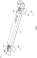
- FIG. 1 shows a partial exploded view of an electronic device according to a first embodiment.
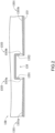
- FIG. 2 shows a partial cross-sectional view of the transmission dock in FIG. 1 .
- a transmission dock 130 includes at least one pivotal concave portion 135, a first wall 131, a second wall 132 and a third wall 133. Details of the structure of the transmission dock 130 are described later.
- the transmission dock 130 is applicable to an electronic device 100.
- the electronic device 100 is, for example but not limited to, a portable computer, and the transmission dock 130 is further applicable to other types of electronic devices.
- the electronic device 100 includes an input unit 110 and the above transmission dock 130.
- the portable computer shown in this embodiment further includes a pluggable and an independently operable display unit 150, so as to facilitate utilization and operations in different scenarios.
- the display unit 150 can be inserted into an accommodating slot 137 of the transmission dock 130 so as to complete the assembly.
- the transmission dock 130 is pivotally connected to the input unit 110.
- the input unit 110 is, for example, a keyboard device or a touch pad, and the transmission dock 130 is capable of pivoting relative to the input unit 110.
- the transmission dock 130 is pivotally connected to the input unit 110 through the at least one pivotal concave portion 135.
- the at least one pivotal concave portion 135 has a first sidewall 1351 and a second sidewall 1352 opposite to each other.
- the first sidewall 1351 and the second sidewall 1352 are left and right sidewalls of the pivotal concave portion 135 in FIG. 2 , respectively.
- the first wall 131 is connected to the first sidewall 1351 and the second sidewall 1352.
- the second wall 132 is connected to the first sidewall 1351 and the second sidewall 1352.
- the third wall 133 is connected to the first sidewall 1351 and the second sidewall 1352.
- the first wall 131 and the second wall 132 are connected to two opposite sides of the third wall 133, respectively.
- An inner surface 1331 of the third wall 133 forms a sloped surface toward each of the first sidewall 1351 and the second sidewall 1352, and each of the sloped surfaces has an opening 1353 at an end thereof.
- the first wall 131 and the second wall 132 are walls on two opposite sides, and the first wall 131, the second wall 132 and the third wall 133 are connected and enclosed to form the accommodating slot 137.
- the inner surface 1331 of the third wall 133 forms two sloped surfaces; that is, an inner surface 1331a of the third wall 133 connected to the first sidewall 1351 forms a descending sloped surface from the left side of the transmission dock 130 toward the first sidewall 1351, and an inner surface 1331b of the third wall 133 connected to the second sidewall 1352 forms a descending sloped surface from the right side of the transmission dock 130 toward the second sidewall 1352.
- the electronic device 100 when the electronic device 100 is in use, water entering an internal space of the transmission dock 130 through between the transmission dock 130 and the display unit 150 can be guided through the inner surfaces 1331a and 1331b to the pivotal concave portion 135, and be discharged through the openings 1353 at the ends of the sloped surfaces.
- the end of the sloped surface refers to a lowermost end of the sloped surface.
- the pivotal concave portion 135 is, for example but not limited to, one in quantity.
- the openings 1353 are provided on the first sidewall 1351 and the sidewall 1352, and are connected to the respective sloped surfaces. As shown in FIG. 2 , an opening 1353a located on the first sidewall 1351 communicates the inner surface 1331a with the pivotal concave portion 135, and an opening 1353b located on the second sidewall 1352 communicates the inner surface 1331b with the pivotal concave portion 135, such that water in the internal space of the transmission dock 130 is guided by the sloped surfaces and discharged through the openings 1353a and 1353b.
- the electronic device 100 further includes a pivotal member 170.
- the pivotal member 170 is provided at the pivotal concave portion 135 such that the input unit 110 and the transmission dock 130 are capable of rotating relative to each other.
- the input unit 110 is pivotally connected to the pivotal concave portion 135, such that the input unit 110 and the transmission dock 130 are capable of pivoting relative to each other.
- FIG. 3 shows a schematic diagram of a transmission dock according to a second embodiment.
- FIG. 4 shows a cross-sectional schematic diagram of the transmission dock in FIG. 3 . Details of structures of the second embodiment similar to those of the first embodiment are omitted herein.
- a pivotal concave portion 235 of the electronic device is two in quantity, and an inner surface 2331 of a third wall 233 between two pivotal concave portions 235a and 235b has a junction 2332. Sloped surfaces are formed from the junction 2332 toward a first sidewall 2351 and a second sidewall 2352, respectively.
- FIG. 3 shows a schematic diagram of a transmission dock according to a second embodiment.
- FIG. 4 shows a cross-sectional schematic diagram of the transmission dock in FIG. 3 . Details of structures of the second embodiment similar to those of the first embodiment are omitted herein.
- a pivotal concave portion 235 of the electronic device is two in quantity, and an inner surface 2331 of a third wall 233 between two pivot
- the inner surface 2331 has the junction 2332 serving as a vertex of the sloped surfaces, and the height of the inner surface 2331 gradually reduces from the junction 2332 toward the second sidewall 2352 and the first sidewall 2351 on the left and right sides.
- the inner surface 2331 forms a descending sloped surface from the junction 2332 toward the second sidewall 2352 of the pivotal concave portion 235a
- the inner surface 2331 forms a descending sloped surface from the junction 2332 toward the first sidewall 2351 of the pivotal concave portion 235b.
- water entering the accommodating slot 137 can be guided to the two pivotal concave portions 235a and 235b and be discharged through two openings 2353 at the ends of the sloped surfaces, respectively.
- the two pivotal concave portions 235a and 235b are located, for example but not limited to, on the relative outermost sides of a transmission dock 230.
- the position of the pivotal concave portion may also be located between the center and the relative outermost side of the transmission dock, with details of the specific structure of this embodiment to be described later.
- the junction 2332 is located, for example but not limited to, at the center of the inner surface 2331 of the third wall 233, so as to evenly guide water entering the internal space to the two pivotal concave portions 235a and 235b on the left and right sides.
- junction 2332 may also be located between the center and the relative outermost side of the inner surface 2331, given that routes from the junction 2332 to the openings 2353 of the two pivotal concave portions 235a and 235b on the left and right sides form descending sloped surfaces.
- FIG. 5 shows a partial cross-sectional view of a transmission dock according to a third embodiment.
- a pivotal concave portion 335 is exemplified by two pivotal concave portions 335a and 335b.
- the pivotal concave portion 335a is located between the center and the relative leftmost side of a transmission dock 330 and closer to the center
- the pivotal concave portion 335b is located between the center and the relative rightmost side of the transmission dock 330 and closer to the center.
- the pivotal concave portion may be provided at any position on the transmission dock, and different quantities of pivotal concave portions may be provided according to requirements.
- an inner surface 3331 of a third wall 333 between the two pivotal concave portions 335a and 335b has a junction 3332, and the junction 3332 forms sloped surfaces toward a second sidewall 3352a of the pivotal concave portion 335a and a first sidewall 3351b of the pivotal concave portion 335b, respectively. As shown in FIG.
- the inner surface 3331 forms a descending sloped surface from the junction 3332 toward the second sidewall 3352a of the pivotal concave portion 335a, and the inner surface 3331 forms a descending sloped surface from the junction 3332 toward the first sidewall 3351b of the pivotal concave portion 335b.
- an inner surface 3331a connected to a first sidewall 3351a of the pivotal concave portion 335a forms a descending sloped surface from the left side of the transmission dock 330 toward the first sidewall 3351a.
- An inner surface 3331b connected to a second sidewall 3352b of the pivotal concave portion 335b forms a descending sloped surface from the right side of the transmission dock 330 toward the second sidewall 3352b.
Landscapes
- Engineering & Computer Science (AREA)
- Theoretical Computer Science (AREA)
- Computer Hardware Design (AREA)
- General Engineering & Computer Science (AREA)
- Human Computer Interaction (AREA)
- Physics & Mathematics (AREA)
- General Physics & Mathematics (AREA)
- Casings For Electric Apparatus (AREA)
- Transceivers (AREA)
- Input Circuits Of Receivers And Coupling Of Receivers And Audio Equipment (AREA)
Abstract
Description
- The present application relates to an electronic device and, more particularly, to a portable electronic device and a transmission dock of the electronic device.
- Regarding a conventional portable electronic device, when frequently transported or used outdoors, water may enter the interior of the electronic device in rainy days or in other circumstances. The life cycle of the electronic device may be undesirably affected in case of water accumulation if the water is not timely discharged.
- Thus, to facilitate discharge of water for such type of portable electronic device, additional holes are usually provided at the bottom of a casing so as to achieve the effect of water drainage. However, the additional holes provided on the casing may cause foreign substances such as water or dust to more likely enter the interior of the electronic device, and an excessive number of holes provided on the casing may also affect aesthetic values of the appearance of the electronic device.
- In view of the above issues, an electronic device provided according to an embodiment includes an input unit and a transmission dock. The transmission dock is pivotally connected to the input unit, and includes at least one pivotal concave portion, a first wall, a second wall and a third wall. The at least one pivotal concave portion has a first sidewall and a second sidewall opposite to each other. The first wall is connected to the first sidewall and the second sidewall. The second wall is connected to the first sidewall and the second sidewall. The third wall is connected to the first sidewall and the second sidewall. The first wall and the second wall are connected to two opposite sides of the third wall, respectively. An inner surface of the third wall forms a sloped surface toward each of the first sidewall and the second sidewall, and each of the sloped surfaces has an opening at an end thereof.
- In some embodiments, the at least one pivotal concave portion is two in quantity, the inner surface of the third wall between the two pivotal concave portions has a junction, and the junction forms a sloped surface toward each of the first sidewall and the second sidewall.
- In some embodiments, the two pivotal concave portions are located on the relative outermost sides of the transmission dock, respectively.
- In some embodiments, the junction is located at the center of the inner surface of the third wall.
- In some embodiments, the height of the sloped surfaces gradually reduces from the junction toward the first sidewall and the second sidewall.
- In some embodiments, the height of the sloped surfaces gradually reduces toward the first sidewall and the second sidewall.
- In some embodiments, each of the openings is provided at the first sidewall and the second sidewall, and is connected to each sloped surface.
- In some embodiments, a display unit is further included. The transmission dock further includes an accommodating slot, which is for accommodating the display unit.
- In some embodiments, a pivotal member is further included. The pivotal member is provided at the at least one pivotal concave portion such that the input unit and the transmission dock are capable of rotating relative to each other.
- A transmission dock provided according to another embodiment includes at least one pivotal concave portion, a first wall, a second wall and a third wall. The at least one pivotal concave portion has a first sidewall and a second sidewall opposite to each other. The first wall is connected to the first sidewall and the second sidewall. The second wall is connected to the first sidewall and the second sidewall. The third wall is connected to the first sidewall and the second sidewall. The first wall and the second wall are connected to two opposite sides of the third wall, respectively. An inner surface of the third wall forms a sloped surface toward each of the first sidewall and the second sidewall, and each of the sloped surfaces has an opening at an end thereof.
- In conclusion, in the electronic device and the transmission dock provided according to the above embodiments, with the inner surfaces formed as sloped surfaces, water inside the electronic device and the transmission dock is guided to the pivotal concave portion, and the water is discharged through openings originally present at the pivotal concave portion, hence avoiding the issue that foreign substances are likely to enter through holes additionally provided on a surface of a casing, and eliminating holes from the casing to maintain an intact appearance of the casing.
-
-
FIG. 1 is a partial exploded view of an electronic device according to a first embodiment; -
FIG. 2 is a partial cross-sectional view of the transmission dock inFIG. 1 ; -
FIG. 3 is a schematic diagram of a transmission dock according to a second embodiment; -
FIG. 4 is a cross-sectional schematic diagram of the transmission dock inFIG. 3 ; and -
FIG. 5 is a partial cross-sectional view of a transmission dock according to a third embodiment. - Refer to
FIG. 1 andFIG. 2 .FIG. 1 shows a partial exploded view of an electronic device according to a first embodiment.FIG. 2 shows a partial cross-sectional view of the transmission dock inFIG. 1 . In the first embodiment, atransmission dock 130 includes at least one pivotalconcave portion 135, afirst wall 131, asecond wall 132 and athird wall 133. Details of the structure of thetransmission dock 130 are described later. Thetransmission dock 130 is applicable to anelectronic device 100. In the first embodiment, theelectronic device 100 is, for example but not limited to, a portable computer, and thetransmission dock 130 is further applicable to other types of electronic devices. In this embodiment, theelectronic device 100 includes aninput unit 110 and theabove transmission dock 130. Moreover, the portable computer shown in this embodiment further includes a pluggable and an independentlyoperable display unit 150, so as to facilitate utilization and operations in different scenarios. When it is needed to connect thedisplay unit 150 to the input unit 110 (for example, a keyboard) for an expansion operation, thedisplay unit 150 can be inserted into anaccommodating slot 137 of thetransmission dock 130 so as to complete the assembly. - The
transmission dock 130 is pivotally connected to theinput unit 110. In the first embodiment, theinput unit 110 is, for example, a keyboard device or a touch pad, and thetransmission dock 130 is capable of pivoting relative to theinput unit 110. - Details of the structure of the
transmission dock 130 are described below. In the first embodiment, thetransmission dock 130 is pivotally connected to theinput unit 110 through the at least one pivotalconcave portion 135. The at least one pivotalconcave portion 135 has afirst sidewall 1351 and asecond sidewall 1352 opposite to each other. In the first embodiment, thefirst sidewall 1351 and thesecond sidewall 1352 are left and right sidewalls of the pivotalconcave portion 135 inFIG. 2 , respectively. Referring toFIG. 1 andFIG. 2 , thefirst wall 131 is connected to thefirst sidewall 1351 and thesecond sidewall 1352. Thesecond wall 132 is connected to thefirst sidewall 1351 and thesecond sidewall 1352. Thethird wall 133 is connected to thefirst sidewall 1351 and thesecond sidewall 1352. Thefirst wall 131 and thesecond wall 132 are connected to two opposite sides of thethird wall 133, respectively. Aninner surface 1331 of thethird wall 133 forms a sloped surface toward each of thefirst sidewall 1351 and thesecond sidewall 1352, and each of the sloped surfaces has anopening 1353 at an end thereof. - In the first embodiment, the
first wall 131 and thesecond wall 132 are walls on two opposite sides, and thefirst wall 131, thesecond wall 132 and thethird wall 133 are connected and enclosed to form theaccommodating slot 137. As shown inFIG. 2 , theinner surface 1331 of thethird wall 133 forms two sloped surfaces; that is, aninner surface 1331a of thethird wall 133 connected to thefirst sidewall 1351 forms a descending sloped surface from the left side of thetransmission dock 130 toward thefirst sidewall 1351, and aninner surface 1331b of thethird wall 133 connected to thesecond sidewall 1352 forms a descending sloped surface from the right side of thetransmission dock 130 toward thesecond sidewall 1352. As such, when theelectronic device 100 is in use, water entering an internal space of thetransmission dock 130 through between thetransmission dock 130 and thedisplay unit 150 can be guided through theinner surfaces concave portion 135, and be discharged through theopenings 1353 at the ends of the sloped surfaces. Herein, the end of the sloped surface refers to a lowermost end of the sloped surface. In the first embodiment, the pivotalconcave portion 135 is, for example but not limited to, one in quantity. - Specifically, with the
inner surface 1331 formed as sloped surfaces, water in the internal space of thetransmission dock 130 of theelectronic device 100 is guided to the pivotalconcave portion 135, and the water can be discharged from theopenings 1353, hence avoiding the issue that foreign substances are likely to enter from holes additionally provided for discharging incoming water on thethird wall 133 of thetransmission dock 130 of theelectronic device 100, and eliminating holes from thethird wall 133 to maintain an intact appearance of thetransmission dock 130. - In the first embodiment, the
openings 1353 are provided on thefirst sidewall 1351 and thesidewall 1352, and are connected to the respective sloped surfaces. As shown inFIG. 2 , anopening 1353a located on thefirst sidewall 1351 communicates theinner surface 1331a with the pivotalconcave portion 135, and anopening 1353b located on thesecond sidewall 1352 communicates theinner surface 1331b with the pivotalconcave portion 135, such that water in the internal space of thetransmission dock 130 is guided by the sloped surfaces and discharged through theopenings - In the first embodiment, the
electronic device 100 further includes apivotal member 170. Thepivotal member 170 is provided at the pivotalconcave portion 135 such that theinput unit 110 and thetransmission dock 130 are capable of rotating relative to each other. As shown inFIG. 1 , with thepivotal member 170, theinput unit 110 is pivotally connected to the pivotalconcave portion 135, such that theinput unit 110 and thetransmission dock 130 are capable of pivoting relative to each other. - Next, refer to
FIG. 3 to FIG. 4 .FIG. 3 shows a schematic diagram of a transmission dock according to a second embodiment.FIG. 4 shows a cross-sectional schematic diagram of the transmission dock inFIG. 3 . Details of structures of the second embodiment similar to those of the first embodiment are omitted herein. In the second embodiment, a pivotalconcave portion 235 of the electronic device is two in quantity, and aninner surface 2331 of athird wall 233 between two pivotalconcave portions junction 2332. Sloped surfaces are formed from thejunction 2332 toward afirst sidewall 2351 and asecond sidewall 2352, respectively. Specifically, as shown inFIG. 4 , theinner surface 2331 has thejunction 2332 serving as a vertex of the sloped surfaces, and the height of theinner surface 2331 gradually reduces from thejunction 2332 toward thesecond sidewall 2352 and thefirst sidewall 2351 on the left and right sides. As shown inFIG. 4 , theinner surface 2331 forms a descending sloped surface from thejunction 2332 toward thesecond sidewall 2352 of the pivotalconcave portion 235a, and theinner surface 2331 forms a descending sloped surface from thejunction 2332 toward thefirst sidewall 2351 of the pivotalconcave portion 235b. Thus, water entering theaccommodating slot 137 can be guided to the two pivotalconcave portions openings 2353 at the ends of the sloped surfaces, respectively. - In the second embodiment, the two pivotal
concave portions transmission dock 230. For example, the position of the pivotal concave portion may also be located between the center and the relative outermost side of the transmission dock, with details of the specific structure of this embodiment to be described later. In the second embodiment, thejunction 2332 is located, for example but not limited to, at the center of theinner surface 2331 of thethird wall 233, so as to evenly guide water entering the internal space to the two pivotalconcave portions junction 2332 may also be located between the center and the relative outermost side of theinner surface 2331, given that routes from thejunction 2332 to theopenings 2353 of the two pivotalconcave portions - Refer to
FIG. 5. FIG. 5 shows a partial cross-sectional view of a transmission dock according to a third embodiment. In the third embodiment, a pivotalconcave portion 335 is exemplified by two pivotalconcave portions FIG. 5 , the pivotalconcave portion 335a is located between the center and the relative leftmost side of atransmission dock 330 and closer to the center, and the pivotalconcave portion 335b is located between the center and the relative rightmost side of thetransmission dock 330 and closer to the center. It is known from the first embodiment, the second embodiment and the third embodiment, the pivotal concave portion may be provided at any position on the transmission dock, and different quantities of pivotal concave portions may be provided according to requirements. In this embodiment, aninner surface 3331 of athird wall 333 between the two pivotalconcave portions junction 3332, and thejunction 3332 forms sloped surfaces toward asecond sidewall 3352a of the pivotalconcave portion 335a and afirst sidewall 3351b of the pivotalconcave portion 335b, respectively. As shown inFIG. 5 , theinner surface 3331 forms a descending sloped surface from thejunction 3332 toward thesecond sidewall 3352a of the pivotalconcave portion 335a, and theinner surface 3331 forms a descending sloped surface from thejunction 3332 toward thefirst sidewall 3351b of the pivotalconcave portion 335b. Moreover, aninner surface 3331a connected to afirst sidewall 3351a of the pivotalconcave portion 335a forms a descending sloped surface from the left side of thetransmission dock 330 toward thefirst sidewall 3351a. Aninner surface 3331b connected to asecond sidewall 3352b of the pivotalconcave portion 335b forms a descending sloped surface from the right side of thetransmission dock 330 toward thesecond sidewall 3352b. Thus, water entering the internal space can be guided to the two pivotalconcave portions openings 3353 at the ends of the sloped surfaces, respectively. - In conclusion, in the electronic device and the transmission dock provided according to the above embodiments, with the inner surfaces formed as sloped surfaces, water entering interiors of the electronic device and the transmission dock is guided to the pivotal concave portions, and the water is discharged through openings at the pivotal concave portions. Because openings of the pivotal concave portions provided for arranging a pivotal assembly are used, the issue that foreign substances are likely to enter through holes additionally provided on a surface of a casing is avoided, and holes are also eliminated from the casing to maintain an intact appearance of the casing.
- The present disclosure is disclosed as the embodiments above. However, these embodiments are not to be construed as limitations to the present disclosure. Slight modifications and variations may be made to the embodiments by a person skilled in the art without departing from the spirit and scope of the present disclosure. Therefore, the scope of legal protection of the present application should be defined by the appended claims.
Claims (11)
- An electronic device, comprising:an input unit; anda transmission dock, pivotally connected to the input unit, the transmission dock comprising:at least one pivotal concave portion, having a first sidewall and a second sidewall opposite to each other;a first wall, connected to the first sidewall and the second sidewall;a second wall, connected to the first sidewall and the second sidewall; anda third wall, connected to the first sidewall and the second sidewall; wherein the first wall and the second wall are connected to two opposite sides of the third wall, respectively, an inner surface of the third wall forms a sloped surface toward each of the first sidewall and the second sidewall, and each of the sloped surfaces has an opening at an end thereof.
- The electronic device according to claim 1, wherein the at least one pivotal concave portion is two in quantity, the inner surface of the third wall located between the two pivotal concave portions has a junction, and the junction forms the sloped surface toward each of the first sidewall and the second sidewall.
- The electronic device according to claim 2, wherein the two pivotal concave portions are located on the relative outermost sides of the transmission dock, respectively.
- The electronic device according to claim 3, wherein the junction is located at a center of the inner surface of the third wall.
- The electronic device according to claim 2, wherein a height of the sloped surfaces gradually reduces from the junction toward the first sidewall and the second sidewall.
- The electronic device according to claim 1, wherein a height of the sloped surfaces gradually reduces toward the first sidewall and the second sidewall.
- The electronic device according to claim 1, wherein each of the openings is provided at the first sidewall and the second sidewall, and is connected to each of the sloped surfaces.
- The electronic device according to claim 1, further comprising a display unit; wherein, the transmission dock further comprises an accommodating slot, which is for accommodating the display unit.
- The electronic device according to claim 8, wherein the first sidewall, the second sidewall and the third wall are connected and enclosed to form the accommodating slot.
- The electronic device according to claim 1, further comprising: a pivotal member, provided at the at least one pivotal concave portion such that the input unit and the transmission dock are capable of rotating relative to each other.
- A transmission dock, comprising:a pivotal concave portion, having a first sidewall and a second sidewall opposite to each other;a first wall, connected to the first sidewall and the second sidewall;a second wall, connected to the first sidewall and the second sidewall; anda third wall, connected to the first sidewall and the second sidewall; wherein the first wall and the second wall are connected to two opposite sides of the third wall, respectively, an inner surface of the third wall forms a sloped surface toward each of the first sidewall and the second sidewall, and each of the sloped surfaces has an opening at an end thereof.
Applications Claiming Priority (2)
| Application Number | Priority Date | Filing Date | Title |
|---|---|---|---|
| US202263309102P | 2022-02-11 | 2022-02-11 | |
| CN202210991555.1A CN116627208A (en) | 2022-02-11 | 2022-08-18 | Transmission base and electronic device |
Publications (2)
| Publication Number | Publication Date |
|---|---|
| EP4227762A1 true EP4227762A1 (en) | 2023-08-16 |
| EP4227762B1 EP4227762B1 (en) | 2026-05-06 |
Family
ID=84360995
Family Applications (1)
| Application Number | Title | Priority Date | Filing Date |
|---|---|---|---|
| EP22208804.9A Active EP4227762B1 (en) | 2022-02-11 | 2022-11-22 | Transmission dock and electronic device |
Country Status (3)
| Country | Link |
|---|---|
| US (2) | US12366886B2 (en) |
| EP (1) | EP4227762B1 (en) |
| AU (1) | AU2022279477B2 (en) |
Families Citing this family (13)
| Publication number | Priority date | Publication date | Assignee | Title |
|---|---|---|---|---|
| TWD231986S (en) * | 2022-01-05 | 2024-07-01 | 神基科技股份有限公司 新北市汐止區南陽街209號7樓 (中華民國) | Seat body of keyboard dock |
| USD1080627S1 (en) * | 2022-06-27 | 2025-06-24 | Getac Technology Corporation | Keyboard dock |
| USD1091551S1 (en) * | 2022-06-27 | 2025-09-02 | Getac Technology Corporation | Keyboard dock |
| USD1091559S1 (en) * | 2022-06-27 | 2025-09-02 | Getac Technology Corporation | Keyboard dock |
| USD1091552S1 (en) * | 2022-06-27 | 2025-09-02 | Getac Technology Corporation | Keyboard dock |
| USD1086139S1 (en) * | 2022-06-27 | 2025-07-29 | Getac Technology Corporation | Keyboard dock |
| USD1086140S1 (en) * | 2022-06-27 | 2025-07-29 | Getac Technology Corporation | Keyboard dock |
| USD1018547S1 (en) * | 2022-06-28 | 2024-03-19 | Getac Technology Corporation | Keyboard dock |
| USD1018546S1 (en) * | 2022-06-28 | 2024-03-19 | Getac Technology Corporation | Keyboard dock |
| USD1015332S1 (en) * | 2022-06-28 | 2024-02-20 | Getac Technology Corporation | Keyboard dock |
| USD1015331S1 (en) * | 2022-06-28 | 2024-02-20 | Getac Technology Corporation | Keyboard dock |
| USD1019653S1 (en) * | 2022-06-28 | 2024-03-26 | Getac Technology Corporation | Keyboard dock |
| USD1019652S1 (en) * | 2022-06-28 | 2024-03-26 | Getac Technology Corporation | Keyboard dock |
Citations (1)
| Publication number | Priority date | Publication date | Assignee | Title |
|---|---|---|---|---|
| US20180109030A1 (en) * | 2015-11-06 | 2018-04-19 | Panasonic Intellectual Property Management Co., Ltd. | Antenna connector and electronic apparatus |
Family Cites Families (5)
| Publication number | Priority date | Publication date | Assignee | Title |
|---|---|---|---|---|
| TWM381095U (en) | 2009-11-18 | 2010-05-21 | Inventec Corp | Housing structure |
| KR102166378B1 (en) | 2014-05-16 | 2020-10-15 | 삼성전자주식회사 | Detachable electronic device |
| JP6735453B2 (en) | 2015-11-06 | 2020-08-05 | パナソニックIpマネジメント株式会社 | Electronics |
| WO2017077669A1 (en) * | 2015-11-06 | 2017-05-11 | パナソニックIpマネジメント株式会社 | Electronic device |
| WO2020154449A1 (en) | 2019-01-22 | 2020-07-30 | Core-Arms, LLC | Mounting system, devices, methods and uses thereof |
-
2022
- 2022-11-04 US US17/980,635 patent/US12366886B2/en active Active
- 2022-11-22 EP EP22208804.9A patent/EP4227762B1/en active Active
- 2022-11-30 AU AU2022279477A patent/AU2022279477B2/en active Active
-
2025
- 2025-06-24 US US19/247,026 patent/US20260072472A1/en active Pending
Patent Citations (1)
| Publication number | Priority date | Publication date | Assignee | Title |
|---|---|---|---|---|
| US20180109030A1 (en) * | 2015-11-06 | 2018-04-19 | Panasonic Intellectual Property Management Co., Ltd. | Antenna connector and electronic apparatus |
Also Published As
| Publication number | Publication date |
|---|---|
| US20260072472A1 (en) | 2026-03-12 |
| US20230259166A1 (en) | 2023-08-17 |
| AU2022279477A1 (en) | 2023-08-31 |
| EP4227762B1 (en) | 2026-05-06 |
| AU2022279477B2 (en) | 2024-02-15 |
| US12366886B2 (en) | 2025-07-22 |
Similar Documents
| Publication | Publication Date | Title |
|---|---|---|
| AU2022279477B2 (en) | Transmission Dock And Electronic Device | |
| US5782370A (en) | Casing capable of protecting an electronic apparatus from static electricity | |
| US20140182814A1 (en) | Air duct | |
| EP1184933A2 (en) | Resonator | |
| CN108445976A (en) | Casing structure | |
| US6415035B1 (en) | Information processing apparatus having speakers | |
| US20130170896A1 (en) | Fixing apparatus for fan | |
| US7641512B2 (en) | Electronic device | |
| CN111864342A (en) | electronic device | |
| CN220473996U (en) | Chip layout structure and chip | |
| CN116627208A (en) | Transmission base and electronic device | |
| KR20210025471A (en) | Dual-port electronic assembly | |
| TWI811068B (en) | Transmission base and electronic device | |
| CN116861839A (en) | Chip layout structure and chip | |
| US20070194444A1 (en) | Protecting apparatus of chip | |
| US20130026894A1 (en) | Computer enclosure | |
| CN120215635A (en) | Electronic Devices | |
| US7170740B1 (en) | Foldable support structure | |
| US8503175B2 (en) | System and method for variable form handheld computer configurable via modular display screen | |
| CN217282931U (en) | Handheld quick-witted sheath and handheld machine | |
| CN113597160B (en) | Shell frame and electronic equipment | |
| CN218918692U (en) | Electronic device | |
| US4982172A (en) | Method of creating a measuring signal access to a waveguide arrangement | |
| CN221592669U (en) | Light guides, housing components and electrical equipment | |
| CN220473998U (en) | Chip and data processing device |
Legal Events
| Date | Code | Title | Description |
|---|---|---|---|
| PUAI | Public reference made under article 153(3) epc to a published international application that has entered the european phase |
Free format text: ORIGINAL CODE: 0009012 |
|
| STAA | Information on the status of an ep patent application or granted ep patent |
Free format text: STATUS: THE APPLICATION HAS BEEN PUBLISHED |
|
| AK | Designated contracting states |
Kind code of ref document: A1 Designated state(s): AL AT BE BG CH CY CZ DE DK EE ES FI FR GB GR HR HU IE IS IT LI LT LU LV MC ME MK MT NL NO PL PT RO RS SE SI SK SM TR |
|
| STAA | Information on the status of an ep patent application or granted ep patent |
Free format text: STATUS: REQUEST FOR EXAMINATION WAS MADE |
|
| 17P | Request for examination filed |
Effective date: 20240205 |
|
| RBV | Designated contracting states (corrected) |
Designated state(s): AL AT BE BG CH CY CZ DE DK EE ES FI FR GB GR HR HU IE IS IT LI LT LU LV MC ME MK MT NL NO PL PT RO RS SE SI SK SM TR |
|
| STAA | Information on the status of an ep patent application or granted ep patent |
Free format text: STATUS: EXAMINATION IS IN PROGRESS |
|
| 17Q | First examination report despatched |
Effective date: 20250729 |
|
| GRAP | Despatch of communication of intention to grant a patent |
Free format text: ORIGINAL CODE: EPIDOSNIGR1 |
|
| STAA | Information on the status of an ep patent application or granted ep patent |
Free format text: STATUS: GRANT OF PATENT IS INTENDED |
|
| INTG | Intention to grant announced |
Effective date: 20260128 |
|
| GRAS | Grant fee paid |
Free format text: ORIGINAL CODE: EPIDOSNIGR3 |
|
| GRAA | (expected) grant |
Free format text: ORIGINAL CODE: 0009210 |
|
| STAA | Information on the status of an ep patent application or granted ep patent |
Free format text: STATUS: THE PATENT HAS BEEN GRANTED |
|
| AK | Designated contracting states |
Kind code of ref document: B1 Designated state(s): AL AT BE BG CH CY CZ DE DK EE ES FI FR GB GR HR HU IE IS IT LI LT LU LV MC ME MK MT NL NO PL PT RO RS SE SI SK SM TR |
|
| REG | Reference to a national code |
Ref country code: CH Ref legal event code: F10 Free format text: ST27 STATUS EVENT CODE: U-0-0-F10-F00 (AS PROVIDED BY THE NATIONAL OFFICE) Effective date: 20260506 Ref country code: GB Ref legal event code: FG4D |