EP4227626A1 - Improved energy storage facility - Google Patents
Improved energy storage facility Download PDFInfo
- Publication number
- EP4227626A1 EP4227626A1 EP23020070.1A EP23020070A EP4227626A1 EP 4227626 A1 EP4227626 A1 EP 4227626A1 EP 23020070 A EP23020070 A EP 23020070A EP 4227626 A1 EP4227626 A1 EP 4227626A1
- Authority
- EP
- European Patent Office
- Prior art keywords
- tanks
- fluid
- energy storage
- storage facility
- thermal
- Prior art date
- Legal status (The legal status is an assumption and is not a legal conclusion. Google has not performed a legal analysis and makes no representation as to the accuracy of the status listed.)
- Granted
Links
Images

Classifications
-
- F—MECHANICAL ENGINEERING; LIGHTING; HEATING; WEAPONS; BLASTING
- F28—HEAT EXCHANGE IN GENERAL
- F28D—HEAT-EXCHANGE APPARATUS, NOT PROVIDED FOR IN ANOTHER SUBCLASS, IN WHICH THE HEAT-EXCHANGE MEDIA DO NOT COME INTO DIRECT CONTACT
- F28D20/00—Heat storage plants or apparatus in general; Regenerative heat-exchange apparatus not covered by groups F28D17/00 or F28D19/00
- F28D20/0034—Heat storage plants or apparatus in general; Regenerative heat-exchange apparatus not covered by groups F28D17/00 or F28D19/00 using liquid heat storage material
-
- F—MECHANICAL ENGINEERING; LIGHTING; HEATING; WEAPONS; BLASTING
- F28—HEAT EXCHANGE IN GENERAL
- F28D—HEAT-EXCHANGE APPARATUS, NOT PROVIDED FOR IN ANOTHER SUBCLASS, IN WHICH THE HEAT-EXCHANGE MEDIA DO NOT COME INTO DIRECT CONTACT
- F28D20/00—Heat storage plants or apparatus in general; Regenerative heat-exchange apparatus not covered by groups F28D17/00 or F28D19/00
- F28D2020/0065—Details, e.g. particular heat storage tanks, auxiliary members within tanks
- F28D2020/0082—Multiple tanks arrangements, e.g. adjacent tanks, tank in tank
-
- Y—GENERAL TAGGING OF NEW TECHNOLOGICAL DEVELOPMENTS; GENERAL TAGGING OF CROSS-SECTIONAL TECHNOLOGIES SPANNING OVER SEVERAL SECTIONS OF THE IPC; TECHNICAL SUBJECTS COVERED BY FORMER USPC CROSS-REFERENCE ART COLLECTIONS [XRACs] AND DIGESTS
- Y02—TECHNOLOGIES OR APPLICATIONS FOR MITIGATION OR ADAPTATION AGAINST CLIMATE CHANGE
- Y02E—REDUCTION OF GREENHOUSE GAS [GHG] EMISSIONS, RELATED TO ENERGY GENERATION, TRANSMISSION OR DISTRIBUTION
- Y02E10/00—Energy generation through renewable energy sources
- Y02E10/40—Solar thermal energy, e.g. solar towers
-
- Y—GENERAL TAGGING OF NEW TECHNOLOGICAL DEVELOPMENTS; GENERAL TAGGING OF CROSS-SECTIONAL TECHNOLOGIES SPANNING OVER SEVERAL SECTIONS OF THE IPC; TECHNICAL SUBJECTS COVERED BY FORMER USPC CROSS-REFERENCE ART COLLECTIONS [XRACs] AND DIGESTS
- Y02—TECHNOLOGIES OR APPLICATIONS FOR MITIGATION OR ADAPTATION AGAINST CLIMATE CHANGE
- Y02E—REDUCTION OF GREENHOUSE GAS [GHG] EMISSIONS, RELATED TO ENERGY GENERATION, TRANSMISSION OR DISTRIBUTION
- Y02E60/00—Enabling technologies; Technologies with a potential or indirect contribution to GHG emissions mitigation
- Y02E60/14—Thermal energy storage
Definitions
- the present invention refers to an improved energy storage facility, through the movement and accumulation of thermal fluids, such as molten salts or thermal oil.
- thermal fluids such as molten salts.
- These storage systems are usually based on tanks or thermal batteries with a modular system of two or three tanks for fluid storage in cold temperature conditions and two or three tanks for hot temperatures. This design factor is conditioned by the use of carbon steel materials in the case of working temperatures below 400 °C and stainless steels in the case of higher temperatures (for example, 500 °C).
- the utility model ES1247480U is relevant, which describes a method for pumping thermal fluids by piston effect and pressurized working gases.
- the invention consists of an improved energy storage facility according to the claims.
- the invention discloses a facility for collecting, storing, and transferring energy for industrial, heating, thermal or electrical energy generation applications, etc.
- the collection and transfer are carried out using a thermal fluid such as molten salts, thermal oils, water, etc.
- the amount of energy stored depends on the number of tanks that can be filled with hot fluid at any time. In the state of the art, such a number corresponds to half of the tanks. In the invention, advantageously, almost all tanks can be used, leaving a single empty tank. Therefore, for a desired energy capacity, the number of tanks, valves and other elements is considerably reduced. As a result, the thermal storage capacity is greater for the same number of tanks or, equivalently, the volume of the facility is less for the same storage capacity. Secondarily, the facility is highly versatile, being very easy to increase or reduce the thermal storage capacity by adding tanks. The addition of a tank directly translates into a tank increase in terms of thermal capacity.
- the present energy storage facility is made up of three or more thermal (cold or hot) fluid storage tanks, a generator or heat source, and heat recovery equipment for its use. At least one of the tanks is a dual tank.
- a "dual tank” will be considered one that is configured to store hot fluid and cold fluid at different times of operation. Therefore, it is made of a material resistant to the highest temperatures and will have the capacity to receive thermal fluid at both temperatures.
- one of the tanks will work all the time with cold fluid in order to reduce its requirements, such as the material, the space occupied due to the insulation, the cost, the conditions of the pipes that lead thereto, etc.
- thermo-mechanical energy Several non-limiting examples of the use of this thermal-mechanical energy are: a turbocharger to raise the pressure of the working gas that empties another tank, as input to the compressor that allows emptying other tanks, generating electricity in a turbine, generating steam for an industrial process... It can also preheat the working gas before it enters the other tank in an exchanger.
- N-2 are dual in order to maximize the facility's capacity. In that case, one tank will always be cold, and another will always be hot. However, the most preferred solution uses N-1 dual tanks and a cold one.
- the facility can be incorporated in one or more ISO or other standard containers, so that it is highly modular since all the tanks are the same (dual) except perhaps one or two of them. Therefore, coupling more containers to the system directly increases, 1:1, the thermal storage capacity of the facility.
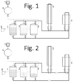
- Figures 1 to 4 represent a diagram of the operation of a first embodiment, in several phases of the process.
- FIG. 1 it is shown an example of an embodiment made up of three or more tanks (1,2,3) that store thermal fluid at two temperatures: hot and cold.
- At least one of the tanks (1,2,3) for example the third tank (3), is a dual tank and is configured to store hot fluid and cold fluid at different times of operation.
- the tanks (1,2,3) comprise the insulation and the necessary elements to work at the temperature of the thermal fluid. With a correct configuration, it is possible to ensure that one of the tanks (1,2,3) always stores cold fluid, thus allowing simpler materials and equipment to be used for that tank (1,2,3).
- the facility also comprises a generator or heat source (4) and heat recovery equipment (5).
- the heat source (4) can be a solar facility, a heat recovery system in a thermal power plant, an electric heater with surplus electricity or from a renewable facility, or any other source of temperature.
- the recovery equipment (5) uses the hot fluid to generate steam in a thermal energy recovery unit, generate electricity, or for any other possible use of the hot fluid.
- the type of heat source (4) or the recovery equipment (5) is not relevant to the invention.
- the first tank (1) stores hot fluid
- the second tank (2) stores cold fluid
- the third tank (3) is empty. It must be considered that "empty” refers to the minimum level of the tank (1,2,3) and that it may contain thermal fluid.
- the facility also includes pressure gauges, thermal probes, branches, bypass, valves, and any other type of device common in this type of facility.
- the pumping or driving of the hot and cold fluids can be by working gas, pressurized, as the method shown in ES1247480U or by high temperature pumps.
- each tank (1,2,3) has an upper inlet for the working gas from a reservoir (6) or high-pressure buffer.
- the working gas can be, for example, gaseous nitrogen or clean, dry air. It is preferably chemically neutral so as not to affect the facility or the thermal fluid. Preferably it will be slightly soluble in the thermal fluid.
- the reservoir (6) is fed by a compressor (7) or another system that ensures that the pressure in the reservoir (6) is the desired one. This reservoir (6) will be stored at very high pressure to store energy that can be used in the event of a power cut or any other emergency situation.
- FIG 2 it is shown a second moment of operation of the facility, in which the third tank (3), dual, is being filled with hot fluid from the second tank (2) through the heat source (4).
- the third tank (3) is full of hot fluid and it begins to empty into the second tank (2), through the recovery equipment (5), returning to the situation in Figure 1 .
- the first tank (1) is emptied through the recovery equipment (5) towards the third tank (3) ( Figure 4 ).
- the third tank (3) has stored fluid at different temperatures. In between, it is possible to carry out a phase of preheating or recovery of noticeable heat by means of a fluid, such as the working gas.
- This working gas is pressurized after emptying the tank (1,2,3) so it has mechanical energy in the form of pressure and high temperature.
- This thermal and/or mechanical energy can be recovered in several ways, for example, in a turbine (8).
- This configuration makes it possible to use all the tanks (1,2,3), except one, to store hot fluid and thus have a much higher capacity than previous solutions without dual tanks.
- thermal energy can be stored in N-1 tanks.
- N-2 dual tanks if there is a hot tank.
- N-1 dual tanks or even that all are dual.
- one or two tanks (1,2,3) will always work with the same temperature.
- the first tank (1) always works hot and the second tank (2) always works cold and the third tank (3) has worked dually to maximize capacity.
- the facility can be incorporated into one or more ISO containers or any other type of standardized container, so that it is possible to connect a variable number of containers to create a facility with one capacity or another.
- Each additional container would have one or more dual tanks, since to increase the capacity, it is only necessary to provide more dual tanks along with their pipes, valves, etc.
- the tank (1,2,3) can be made up of the container itself.
Landscapes
- Engineering & Computer Science (AREA)
- Physics & Mathematics (AREA)
- Thermal Sciences (AREA)
- Mechanical Engineering (AREA)
- General Engineering & Computer Science (AREA)
- Filling Or Discharging Of Gas Storage Vessels (AREA)
- Engine Equipment That Uses Special Cycles (AREA)
Abstract
Description
- The present invention refers to an improved energy storage facility, through the movement and accumulation of thermal fluids, such as molten salts or thermal oil.
- The field of energy storage has evolved enormously with the need to store, transport, and manage the use of thermal fluids, such as molten salts. These storage systems are usually based on tanks or thermal batteries with a modular system of two or three tanks for fluid storage in cold temperature conditions and two or three tanks for hot temperatures. This design factor is conditioned by the use of carbon steel materials in the case of working temperatures below 400 °C and stainless steels in the case of higher temperatures (for example, 500 °C).
- This definition of design as a storage tank at low or high temperature places a restriction on the specific use of each tank. For example, tanks defined as for low temperature do not allow the storage of fluids at temperatures above 400 °C. This definition of the working temperature conditions of each one of the tanks or thermal batteries reduces the initial investment required by the system, but reduces the total thermal storage capacity, availability, and manageability of the facility for a similar modularity.
- The utility model
ES1247480U - The applicant is not aware of any device or facility that can be considered similar to the invention, or that proposes a solution to the same technical problems.
- The invention consists of an improved energy storage facility according to the claims.
- The invention discloses a facility for collecting, storing, and transferring energy for industrial, heating, thermal or electrical energy generation applications, etc. The collection and transfer are carried out using a thermal fluid such as molten salts, thermal oils, water, etc.
- In such a system, the amount of energy stored depends on the number of tanks that can be filled with hot fluid at any time. In the state of the art, such a number corresponds to half of the tanks. In the invention, advantageously, almost all tanks can be used, leaving a single empty tank. Therefore, for a desired energy capacity, the number of tanks, valves and other elements is considerably reduced. As a result, the thermal storage capacity is greater for the same number of tanks or, equivalently, the volume of the facility is less for the same storage capacity. Secondarily, the facility is highly versatile, being very easy to increase or reduce the thermal storage capacity by adding tanks. The addition of a tank directly translates into a tank increase in terms of thermal capacity.
- The present energy storage facility is made up of three or more thermal (cold or hot) fluid storage tanks, a generator or heat source, and heat recovery equipment for its use. At least one of the tanks is a dual tank. A "dual tank" will be considered one that is configured to store hot fluid and cold fluid at different times of operation. Therefore, it is made of a material resistant to the highest temperatures and will have the capacity to receive thermal fluid at both temperatures. Preferably, one of the tanks will work all the time with cold fluid in order to reduce its requirements, such as the material, the space occupied due to the insulation, the cost, the conditions of the pipes that lead thereto, etc.
- If, in addition, the movement of the fluids is carried out by means of a piston effect, using a pressurized working gas, it results in a system of low complexity, with reduced maintenance and almost zero possibility of leaks. An example can be seen in
ES1247480U - For example, in a facility with N tanks, at least N-2 are dual in order to maximize the facility's capacity. In that case, one tank will always be cold, and another will always be hot. However, the most preferred solution uses N-1 dual tanks and a cold one.
- The facility can be incorporated in one or more ISO or other standard containers, so that it is highly modular since all the tanks are the same (dual) except perhaps one or two of them. Therefore, coupling more containers to the system directly increases, 1:1, the thermal storage capacity of the facility.
- Other particular embodiments will be discussed below with the support of the figures.
- For a better understanding of the invention, the following figures are included.
-
Figures 1 to 4 represent a diagram of the operation of a first embodiment, in several phases of the process. - Next, an embodiment of the invention will be briefly described as an illustrative and non-limiting example thereof.
- In
Figure 1 it is shown an example of an embodiment made up of three or more tanks (1,2,3) that store thermal fluid at two temperatures: hot and cold. At least one of the tanks (1,2,3), for example the third tank (3), is a dual tank and is configured to store hot fluid and cold fluid at different times of operation. The tanks (1,2,3) comprise the insulation and the necessary elements to work at the temperature of the thermal fluid. With a correct configuration, it is possible to ensure that one of the tanks (1,2,3) always stores cold fluid, thus allowing simpler materials and equipment to be used for that tank (1,2,3). - The facility also comprises a generator or heat source (4) and heat recovery equipment (5). The heat source (4) can be a solar facility, a heat recovery system in a thermal power plant, an electric heater with surplus electricity or from a renewable facility, or any other source of temperature. The recovery equipment (5) uses the hot fluid to generate steam in a thermal energy recovery unit, generate electricity, or for any other possible use of the hot fluid. The type of heat source (4) or the recovery equipment (5) is not relevant to the invention. Likewise, there can be more than one heat source (4) and more than one recovery equipment (5), the same or different, in series or in parallel. In the figures it is depicted a single pipe that moves hot or cold fluid depending on the moment of operation, as it is the most technically simple solution. However, it is possible to have a pipe for cold fluid and another one for hot fluid with their respective inputs to the dual tanks.
- At the moment depicted in
Figure 1 , the first tank (1) stores hot fluid, the second tank (2) stores cold fluid, and the third tank (3) is empty. It must be considered that "empty" refers to the minimum level of the tank (1,2,3) and that it may contain thermal fluid. - The facility also includes pressure gauges, thermal probes, branches, bypass, valves, and any other type of device common in this type of facility. The pumping or driving of the hot and cold fluids can be by working gas, pressurized, as the method shown in
ES1247480U - In the figures it is shown the embodiment with driving through pressurized gas. It can be seen that each tank (1,2,3) has an upper inlet for the working gas from a reservoir (6) or high-pressure buffer. The working gas can be, for example, gaseous nitrogen or clean, dry air. It is preferably chemically neutral so as not to affect the facility or the thermal fluid. Preferably it will be slightly soluble in the thermal fluid. The reservoir (6) is fed by a compressor (7) or another system that ensures that the pressure in the reservoir (6) is the desired one. This reservoir (6) will be stored at very high pressure to store energy that can be used in the event of a power cut or any other emergency situation. It is also possible to use the off-peak hours to fill the reservoir (6) or buffer, as well as another source of renewable electrical energy, with the purpose of having pressure energy stored in the gas so that the loading and unloading operations of the thermal fluid of the system need not be simultaneous in time. The thermal fluid leaves the bottom of the tank (1,2,3). The return entry will be from above. The gas or working fluid will enter from above to perform the piston effect.
- In
Figure 2 it is shown a second moment of operation of the facility, in which the third tank (3), dual, is being filled with hot fluid from the second tank (2) through the heat source (4). InFigure 3 , the third tank (3) is full of hot fluid and it begins to empty into the second tank (2), through the recovery equipment (5), returning to the situation inFigure 1 . Once the third tank is empty, the first tank (1) is emptied through the recovery equipment (5) towards the third tank (3) (Figure 4 ). - Therefore, it can be seen that in
Figures 2 and4 the third tank (3) has stored fluid at different temperatures. In between, it is possible to carry out a phase of preheating or recovery of noticeable heat by means of a fluid, such as the working gas. This working gas is pressurized after emptying the tank (1,2,3) so it has mechanical energy in the form of pressure and high temperature. This thermal and/or mechanical energy can be recovered in several ways, for example, in a turbine (8). - This configuration makes it possible to use all the tanks (1,2,3), except one, to store hot fluid and thus have a much higher capacity than previous solutions without dual tanks. In a facility with N tanks, thermal energy can be stored in N-1 tanks. For that purpose, it is enough that there are N-2 dual tanks, if there is a hot tank. It is also possible to use N-1 dual tanks or even that all are dual. For that purpose, one or two tanks (1,2,3) will always work with the same temperature. In the case described in this section of the specification, the first tank (1) always works hot and the second tank (2) always works cold and the third tank (3) has worked dually to maximize capacity.
- If desired, the facility can be incorporated into one or more ISO containers or any other type of standardized container, so that it is possible to connect a variable number of containers to create a facility with one capacity or another. Each additional container would have one or more dual tanks, since to increase the capacity, it is only necessary to provide more dual tanks along with their pipes, valves, etc. For example, the tank (1,2,3) can be made up of the container itself.
Claims (8)
- Improved energy storage facility, made up of three or more thermal fluid storage tanks (1,2,3), a heat source (4) and recovery equipment (5), characterized in that at least one of the tanks (1,2,3) is a dual tank configured to store hot fluid and cold fluid at different times of operation.
- Improved energy storage facility, according to claim 1, characterized in that it comprises N tanks, of which at least N-2 are dual.
- Improved energy storage facility, according to claim 2, characterized in that it comprises at least N-1 dual tanks.
- Improved energy storage facility, according to claim 1, characterized in that it is configured so that one of the tanks (1,2,3) works all the time with cold fluid.
- Improved energy storage facility, according to claim 1, characterized in that the thermal fluid is driven by the piston effect of a pressurized working gas.
- Improved energy storage facility, according to claim 5, characterized in that it comprises a noticeable heat recovery system in the dual tank in the passage of hot thermal fluid to cold thermal fluid by means of working gas.
- Improved energy storage facility, according to claim 1, characterized in that it is incorporated into one or more standardized containers.
- Improved energy storage facility, according to claim 5, characterized in that it comprises a system for recovering the mechanical and/or thermal energy of the pressurized working gas once the thermal fluid transfer processes between tanks have been carried out.
Applications Claiming Priority (1)
| Application Number | Priority Date | Filing Date | Title |
|---|---|---|---|
| ES202230199U ES1288369Y (en) | 2022-02-09 | 2022-02-09 | IMPROVED ENERGY STORAGE FACILITY |
Publications (3)
| Publication Number | Publication Date |
|---|---|
| EP4227626A1 true EP4227626A1 (en) | 2023-08-16 |
| EP4227626B1 EP4227626B1 (en) | 2026-04-08 |
| EP4227626C0 EP4227626C0 (en) | 2026-04-08 |
Family
ID=80815938
Family Applications (1)
| Application Number | Title | Priority Date | Filing Date |
|---|---|---|---|
| EP23020070.1A Active EP4227626B1 (en) | 2022-02-09 | 2023-02-08 | Improved energy storage facility |
Country Status (2)
| Country | Link |
|---|---|
| EP (1) | EP4227626B1 (en) |
| ES (1) | ES1288369Y (en) |
Cited By (1)
| Publication number | Priority date | Publication date | Assignee | Title |
|---|---|---|---|---|
| CN120720902A (en) * | 2025-08-21 | 2025-09-30 | 中国电建集团华东勘测设计研究院有限公司 | Compressed gas energy storage power station heat recovery and utilization system and operation method |
Citations (4)
| Publication number | Priority date | Publication date | Assignee | Title |
|---|---|---|---|---|
| WO2016150461A1 (en) * | 2015-03-20 | 2016-09-29 | Siemens Aktiengesellschaft | Thermal energy storage plant |
| ES1247480U (en) | 2020-04-15 | 2020-06-09 | Rpow Consulting S L | ENERGY STORAGE INSTALLATION (Machine-translation by Google Translate, not legally binding) |
| WO2020204933A1 (en) * | 2019-04-04 | 2020-10-08 | Terrafore Technologies, Llc | Thermocline thermal energy storage in multiple tanks |
| WO2021130648A1 (en) * | 2019-12-23 | 2021-07-01 | Energy Dome S.P.A. | Plant and process for storing and discharging thermal energy |
-
2022
- 2022-02-09 ES ES202230199U patent/ES1288369Y/en active Active
-
2023
- 2023-02-08 EP EP23020070.1A patent/EP4227626B1/en active Active
Patent Citations (4)
| Publication number | Priority date | Publication date | Assignee | Title |
|---|---|---|---|---|
| WO2016150461A1 (en) * | 2015-03-20 | 2016-09-29 | Siemens Aktiengesellschaft | Thermal energy storage plant |
| WO2020204933A1 (en) * | 2019-04-04 | 2020-10-08 | Terrafore Technologies, Llc | Thermocline thermal energy storage in multiple tanks |
| WO2021130648A1 (en) * | 2019-12-23 | 2021-07-01 | Energy Dome S.P.A. | Plant and process for storing and discharging thermal energy |
| ES1247480U (en) | 2020-04-15 | 2020-06-09 | Rpow Consulting S L | ENERGY STORAGE INSTALLATION (Machine-translation by Google Translate, not legally binding) |
Cited By (1)
| Publication number | Priority date | Publication date | Assignee | Title |
|---|---|---|---|---|
| CN120720902A (en) * | 2025-08-21 | 2025-09-30 | 中国电建集团华东勘测设计研究院有限公司 | Compressed gas energy storage power station heat recovery and utilization system and operation method |
Also Published As
| Publication number | Publication date |
|---|---|
| EP4227626B1 (en) | 2026-04-08 |
| ES1288369U (en) | 2022-03-25 |
| ES1288369Y (en) | 2022-06-15 |
| EP4227626C0 (en) | 2026-04-08 |
Similar Documents
| Publication | Publication Date | Title |
|---|---|---|
| Steinmann | Thermo-mechanical concepts for bulk energy storage | |
| EP2753861B2 (en) | Method and apparatus for power storage | |
| US11591957B2 (en) | Energy storage apparatus and method | |
| US11619213B1 (en) | Renewable power generation system and method | |
| US20140260246A1 (en) | Dispatchable power plant and method for using the same | |
| WO2013119145A2 (en) | Method for accumulating, storing and recovering mechanical energy and apparatus for the implementation thereof (embodiments) | |
| Heo et al. | Evaluation of various large-scale energy storage technologies for flexible operation of existing pressurized water reactors | |
| CN221074569U (en) | CAES system shared by modularized configuration heat exchange systems | |
| KR20200110719A (en) | Combined power generation system using cold heat of liquefied natural gas | |
| EP4227626B1 (en) | Improved energy storage facility | |
| CN102803662B (en) | System And Method For Accumulating Steam In Tanks For Solar Use | |
| CN116105524B (en) | A heat storage and exchange integrated molten salt energy storage system and working method thereof | |
| US4130992A (en) | Arrangement for the storage of energy in power plants | |
| RU70312U1 (en) | INSTALLATION FOR ENSURING MANEUVERABILITY OF ATOMIC ELECTRIC STATIONS | |
| AU2020292109B2 (en) | Thermal energy battery | |
| DE102010036530A1 (en) | Heat engine for converting thermal energy into mechanical energy used to generate electricity, and method of operating such a heat engine | |
| EP2765357B1 (en) | Steam power plant with an additional flexible solar system for the flexible integration of solar energy | |
| WO2016173705A2 (en) | Method and device for energy storage with air | |
| EP2589761B1 (en) | Steam power plant with heat reservoir and method for operating a steam power plant | |
| Pan et al. | Thermoeconomic analysis of a novel liquefied biomethane-air energy storage system | |
| Forsberg | 1000-MW CSP with 100-gigawatt-hour crushed-rock heat storage to replace dispatchable fossil-fuel electricity | |
| CN115574307A (en) | Hundred megawatt subcritical water compression saturated steam generation system and energy storage method | |
| WO2015136351A2 (en) | Dispatchable power plant and method for using the same | |
| WO2021210986A1 (en) | Thermal energy storage device and an auxiliary container for thermal energy storage device | |
| DE102011014531A1 (en) | Method for integration of renewable energy into power supply for, e.g. commercial application, involves receiving cooled warm water of heating and hot water supply system via water circulation channel by storage system from bottom side |
Legal Events
| Date | Code | Title | Description |
|---|---|---|---|
| PUAI | Public reference made under article 153(3) epc to a published international application that has entered the european phase |
Free format text: ORIGINAL CODE: 0009012 |
|
| STAA | Information on the status of an ep patent application or granted ep patent |
Free format text: STATUS: THE APPLICATION HAS BEEN PUBLISHED |
|
| AK | Designated contracting states |
Kind code of ref document: A1 Designated state(s): AL AT BE BG CH CY CZ DE DK EE ES FI FR GB GR HR HU IE IS IT LI LT LU LV MC ME MK MT NL NO PL PT RO RS SE SI SK SM TR |
|
| RAP3 | Party data changed (applicant data changed or rights of an application transferred) |
Owner name: KYOTO TECHNOLOGY SPAIN, S.L. |
|
| STAA | Information on the status of an ep patent application or granted ep patent |
Free format text: STATUS: REQUEST FOR EXAMINATION WAS MADE |
|
| 17P | Request for examination filed |
Effective date: 20240215 |
|
| RBV | Designated contracting states (corrected) |
Designated state(s): AL AT BE BG CH CY CZ DE DK EE ES FI FR GB GR HR HU IE IS IT LI LT LU LV MC ME MK MT NL NO PL PT RO RS SE SI SK SM TR |
|
| STAA | Information on the status of an ep patent application or granted ep patent |
Free format text: STATUS: EXAMINATION IS IN PROGRESS |
|
| 17Q | First examination report despatched |
Effective date: 20250410 |
|
| GRAP | Despatch of communication of intention to grant a patent |
Free format text: ORIGINAL CODE: EPIDOSNIGR1 |
|
| STAA | Information on the status of an ep patent application or granted ep patent |
Free format text: STATUS: GRANT OF PATENT IS INTENDED |
|
| INTG | Intention to grant announced |
Effective date: 20250904 |
|
| GRAS | Grant fee paid |
Free format text: ORIGINAL CODE: EPIDOSNIGR3 |
|
| GRAA | (expected) grant |
Free format text: ORIGINAL CODE: 0009210 |
|
| STAA | Information on the status of an ep patent application or granted ep patent |
Free format text: STATUS: THE PATENT HAS BEEN GRANTED |
|
| AK | Designated contracting states |
Kind code of ref document: B1 Designated state(s): AL AT BE BG CH CY CZ DE DK EE ES FI FR GB GR HR HU IE IS IT LI LT LU LV MC ME MK MT NL NO PL PT RO RS SE SI SK SM TR |
|
| REG | Reference to a national code |
Ref country code: CH Ref legal event code: F10 Free format text: ST27 STATUS EVENT CODE: U-0-0-F10-F00 (AS PROVIDED BY THE NATIONAL OFFICE) Effective date: 20260408 Ref country code: GB Ref legal event code: FG4D |
|
| REG | Reference to a national code |
Ref country code: DE Ref legal event code: R096 Ref document number: 602023014680 Country of ref document: DE |
|
| REG | Reference to a national code |
Ref country code: IE Ref legal event code: FG4D |
|
| REG | Reference to a national code |
Ref country code: CH Ref legal event code: W10 Free format text: ST27 STATUS EVENT CODE: U-0-0-W10-W00 (AS PROVIDED BY THE NATIONAL OFFICE) Effective date: 20260604 |
|
| U01 | Request for unitary effect filed |
Effective date: 20260506 |
|
| RAP4 | Party data changed (patent owner data changed or rights of a patent transferred) |
Owner name: KYOTO TECHNOLOGY SPAIN, S.L. |
|
| U07 | Unitary effect registered |
Designated state(s): AT BE BG DE DK EE FI FR IT LT LU LV MT NL PT RO SE SI Effective date: 20260529 |