EP4227609A1 - Vapor-to-air heat exchanger for aircraft powerplant - Google Patents
Vapor-to-air heat exchanger for aircraft powerplant Download PDFInfo
- Publication number
- EP4227609A1 EP4227609A1 EP23156378.4A EP23156378A EP4227609A1 EP 4227609 A1 EP4227609 A1 EP 4227609A1 EP 23156378 A EP23156378 A EP 23156378A EP 4227609 A1 EP4227609 A1 EP 4227609A1
- Authority
- EP
- European Patent Office
- Prior art keywords
- vessel
- condenser
- vapor
- configuration
- pneumatic
- Prior art date
- Legal status (The legal status is an assumption and is not a legal conclusion. Google has not performed a legal analysis and makes no representation as to the accuracy of the status listed.)
- Granted
Links
Images

Classifications
-
- B—PERFORMING OPERATIONS; TRANSPORTING
- B64—AIRCRAFT; AVIATION; COSMONAUTICS
- B64D—EQUIPMENT FOR FITTING IN OR TO AIRCRAFT; FLIGHT SUITS; PARACHUTES; ARRANGEMENT OR MOUNTING OF POWER PLANTS OR PROPULSION TRANSMISSIONS IN AIRCRAFT
- B64D33/00—Arrangement in aircraft of power plant parts or auxiliaries not otherwise provided for
- B64D33/08—Arrangement in aircraft of power plant parts or auxiliaries not otherwise provided for of power plant cooling systems
- B64D33/10—Radiator arrangement
- B64D33/12—Radiator arrangement of retractable type
-
- F—MECHANICAL ENGINEERING; LIGHTING; HEATING; WEAPONS; BLASTING
- F28—HEAT EXCHANGE IN GENERAL
- F28D—HEAT-EXCHANGE APPARATUS, NOT PROVIDED FOR IN ANOTHER SUBCLASS, IN WHICH THE HEAT-EXCHANGE MEDIA DO NOT COME INTO DIRECT CONTACT
- F28D9/00—Heat-exchange apparatus having stationary plate-like or laminated conduit assemblies for both heat-exchange media, the media being in contact with different sides of a conduit wall
- F28D9/0031—Heat-exchange apparatus having stationary plate-like or laminated conduit assemblies for both heat-exchange media, the media being in contact with different sides of a conduit wall the conduits for one heat-exchange medium being formed by paired plates touching each other
-
- F—MECHANICAL ENGINEERING; LIGHTING; HEATING; WEAPONS; BLASTING
- F25—REFRIGERATION OR COOLING; COMBINED HEATING AND REFRIGERATION SYSTEMS; HEAT PUMP SYSTEMS; MANUFACTURE OR STORAGE OF ICE; LIQUEFACTION SOLIDIFICATION OF GASES
- F25B—REFRIGERATION MACHINES, PLANTS OR SYSTEMS; COMBINED HEATING AND REFRIGERATION SYSTEMS; HEAT PUMP SYSTEMS
- F25B39/00—Evaporators; Condensers
- F25B39/04—Condensers
-
- F—MECHANICAL ENGINEERING; LIGHTING; HEATING; WEAPONS; BLASTING
- F28—HEAT EXCHANGE IN GENERAL
- F28D—HEAT-EXCHANGE APPARATUS, NOT PROVIDED FOR IN ANOTHER SUBCLASS, IN WHICH THE HEAT-EXCHANGE MEDIA DO NOT COME INTO DIRECT CONTACT
- F28D9/00—Heat-exchange apparatus having stationary plate-like or laminated conduit assemblies for both heat-exchange media, the media being in contact with different sides of a conduit wall
- F28D9/0006—Heat-exchange apparatus having stationary plate-like or laminated conduit assemblies for both heat-exchange media, the media being in contact with different sides of a conduit wall the plate-like or laminated conduits being enclosed within a pressure vessel
-
- F—MECHANICAL ENGINEERING; LIGHTING; HEATING; WEAPONS; BLASTING
- F28—HEAT EXCHANGE IN GENERAL
- F28D—HEAT-EXCHANGE APPARATUS, NOT PROVIDED FOR IN ANOTHER SUBCLASS, IN WHICH THE HEAT-EXCHANGE MEDIA DO NOT COME INTO DIRECT CONTACT
- F28D9/00—Heat-exchange apparatus having stationary plate-like or laminated conduit assemblies for both heat-exchange media, the media being in contact with different sides of a conduit wall
- F28D9/0087—Heat-exchange apparatus having stationary plate-like or laminated conduit assemblies for both heat-exchange media, the media being in contact with different sides of a conduit wall with flexible plates
-
- F—MECHANICAL ENGINEERING; LIGHTING; HEATING; WEAPONS; BLASTING
- F28—HEAT EXCHANGE IN GENERAL
- F28F—DETAILS OF HEAT-EXCHANGE AND HEAT-TRANSFER APPARATUS, OF GENERAL APPLICATION
- F28F21/00—Constructions of heat-exchange apparatus characterised by the selection of particular materials
- F28F21/08—Constructions of heat-exchange apparatus characterised by the selection of particular materials of metal
-
- F—MECHANICAL ENGINEERING; LIGHTING; HEATING; WEAPONS; BLASTING
- F28—HEAT EXCHANGE IN GENERAL
- F28D—HEAT-EXCHANGE APPARATUS, NOT PROVIDED FOR IN ANOTHER SUBCLASS, IN WHICH THE HEAT-EXCHANGE MEDIA DO NOT COME INTO DIRECT CONTACT
- F28D21/00—Heat-exchange apparatus not covered by any of the groups F28D1/00 - F28D20/00
- F28D2021/0019—Other heat exchangers for particular applications; Heat exchange systems not otherwise provided for
- F28D2021/0021—Other heat exchangers for particular applications; Heat exchange systems not otherwise provided for for aircrafts or cosmonautics
-
- F—MECHANICAL ENGINEERING; LIGHTING; HEATING; WEAPONS; BLASTING
- F28—HEAT EXCHANGE IN GENERAL
- F28D—HEAT-EXCHANGE APPARATUS, NOT PROVIDED FOR IN ANOTHER SUBCLASS, IN WHICH THE HEAT-EXCHANGE MEDIA DO NOT COME INTO DIRECT CONTACT
- F28D21/00—Heat-exchange apparatus not covered by any of the groups F28D1/00 - F28D20/00
- F28D2021/0019—Other heat exchangers for particular applications; Heat exchange systems not otherwise provided for
- F28D2021/0026—Other heat exchangers for particular applications; Heat exchange systems not otherwise provided for for combustion engines, e.g. for gas turbines or for Stirling engines
-
- F—MECHANICAL ENGINEERING; LIGHTING; HEATING; WEAPONS; BLASTING
- F28—HEAT EXCHANGE IN GENERAL
- F28F—DETAILS OF HEAT-EXCHANGE AND HEAT-TRANSFER APPARATUS, OF GENERAL APPLICATION
- F28F2275/00—Fastening; Joining
- F28F2275/06—Fastening; Joining by welding
Definitions
- the present invention relates generally to aircraft engines and, more particularly, to heat exchanger systems for aircraft powerplants.
- Aircraft powerplants have stringent cooling requirements, some of which are typically addressed by liquid-to-air heat exchangers.
- a closed-loop fluidic circuit carries a liquid coolant from the vicinity of a source of heat of the powerplant, to a heat exchanger at which the liquid coolant rejects the heat into cooling airflow(s).
- the quantity, locations and overall output of the sources of heat requiring cooling have evolved, which presents challenges in implementing heat exchangers that are suitable in terms of size, weight and cooling capacity.
- a vapor-to-air heat exchanger for an aircraft powerplant, comprising: a pressurized vapor source supplying vapor; and a condenser including a condenser inlet in fluid communication with the pressurized vapor source to receive the vapor, a condenser outlet, and at least one pneumatic vessel defining a cavity in fluid communication between the condenser inlet and the condenser outlet, the at least one pneumatic vessel being reversibly inflatable to be configurable between a collapsed vessel configuration and an inflated vessel configuration, a volume of the cavity being greater in the inflated vessel configuration than in the collapsed vessel configuration, the at least one pneumatic vessel being inflatable from the collapsed vessel configuration to the inflated vessel configuration when the cavity is pressurized by the vapor.
- vapor-to-air heat exchanger as defined above and described herein may further include one or more of the following features, in whole or in part, and in any combination.
- the at least one pneumatic vessel is formed of flexible film sheets welded to one another.
- At least one sheet of the flexible film sheets includes one or more of: a metallic layer; and a composite layer.
- the at least one pneumatic vessel includes a top tubular portion proximate to the condenser inlet, a bottom tubular portion proximate to the condenser outlet, and at least one transverse tubular portion fluidly connected between the top tubular portion and the bottom tubular portion.
- the condenser comprises a plurality of pneumatic vessels including the at least one pneumatic vessel, and the top tubular portion defines a portion of a supply manifold of the condenser.
- the condenser comprises a plurality of pneumatic vessels including the at least one pneumatic vessel, and the bottom tubular portion defines a portion of a drainage manifold of the condenser.
- the heat exchanger includes one or more of: a pressure regulating valve between the pressurized vapor source and the condenser inlet; and a pump between the condenser outlet and the pressurized vapor source.
- the heat exchanger includes a support structure attached to the at least one pneumatic vessel for holding the at least one pneumatic vessel in a deployed position.
- the support structure is configurable between a collapsed support configuration and an inflated support configuration, the support structure being inflatable from the collapsed support configuration to the inflated support configuration.
- the at least one pneumatic vessel is in the inflated vessel configuration when the cavity is pressurized by the vapor to at least a nominal pressure, the pressurized vapor source supplying the vapor at a source pressure of at least the nominal pressure.
- a vapor-to-air heat exchanger for an aircraft powerplant, comprising: an evaporator supplying vapor; and a condenser including: a condenser inlet in fluid communication with the evaporator to receive vapor therefrom; a condenser outlet; and an array of pneumatic vessels spaced from one another in an array orientation so as to define at least one air flow path along a path orientation transverse to the array orientation, at least one pneumatic vessel of the array of pneumatic vessels defining an cavity, a plane transverse to the array orientation extending through the cavity, the cavity being in fluid communication between the condenser inlet and the condenser outlet, the at least one pneumatic vessel being inflatable when the cavity is pressurized by the vapor to transition from a collapsed vessel configuration to an inflated vessel configuration, a size of the at least one pneumatic vessel in the array orientation being greater in the inflated vessel configuration than in the collapsed vessel configuration.
- vapor-to-air heat exchanger as defined above and described herein may further include one or more of the following features, in whole or in part, and in any combination.
- the at least one pneumatized vessel includes a top tubular portion proximate to the condenser inlet, a bottom tubular portion proximate to the condenser outlet, and a plurality of transverse tubular portions fluidly connected between the top and the bottom tubular portions and spaced from one another in the path orientation.
- the at least one pneumatic vessel includes a first vessel and a second vessel next to one another on either side of the at least one flow path, a first plurality of transverse tubular portions of the first vessel and a second plurality of transverse tubular portions of the second vessel being in a staggered relationship in the path orientation.
- a powerplant for an aircraft comprising: a power unit rejecting heat at a nominal heat rejection rate; and a vapor-to-air heat exchanger including: an evaporator thermally coupled to the power unit so as to supply vapor at a nominal pressure upon the power unit rejecting heat at the nominal heat rejection rate; and a condenser including a condenser inlet downstream of the evaporator, a condenser outlet, and at least one pneumatic vessel being inflatable and defining an cavity in fluid communication between the condenser inlet and the condenser outlet, the at least one pneumatic vessel being configurable between a collapsed vessel configuration and an inflated vessel configuration, the at least one pneumatic vessel being inflatable from the collapsed vessel configuration to the inflated vessel configuration upon the cavity being pressurized up to the nominal pressure.
- the powerplant as defined above and described herein may further include one or more of the following features, in whole or in part, and in any combination.
- the at least one pneumatic vessel is constructed of a pair of flexible film sheets welded to one another.
- the at least one pneumatic vessel includes a top tubular portion proximate to the condenser inlet, a bottom tubular portion proximate to the condenser outlet, and at least one transverse tubular portion fluidly connected between the top and the bottom tubular portions.
- the condenser comprises a plurality of pneumatic vessels including the at least one pneumatic vessel, and the top tubular portion defines a portion of a supply manifold of the condenser.
- the powerplant includes one or more of: a pressure regulating valve between the evaporator and the condenser inlet; and a pump between the condenser outlet and the evaporator.
- the powerplant includes a support structure supporting the at least one pneumatic vessel and a carcass defining an air cavity, the support structure affixed to the carcass so as to orient the at least one pneumatic vessel relative to the air cavity.
- the support structure is configurable between a collapsed support configuration and an inflated support configuration, the support structure being inflatable from the collapsed support configuration to the inflated support configuration.
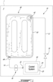
- a heat exchanger 10 is generally shown at 10, depicted on Fig. 1 in a heat exchange relationship between a cooled system 20, or heat source, of a powerplant 1 and an environment E of the powerplant 1.
- the powerplant 1 may be any suitable aircraft engine, whether a gas turbine engine, a primarily electric engine, a hybrid-electric engine, or any combination of same.
- the cooled system 20 may be any component of the powerplant 1 that employ cooling.
- the cooled system 20 may be a power unit of the powerplant 1, such as a fuel system in the case of a powerplant including an internal combustion engine, or a battery pack in the case of a powerplant including an electric motor.
- the cooling of the battery pack via the heat exchanger 10 may assist in maintaining the integrity of the battery pack as well as suitable lifespan and charging and discharging regimes.
- the cooled system 20 may also be an oil system of the powerplant 1.
- the cooled system 20 may also be a turbine case of a gas turbine engine. The cooling of the turbine case may assist in maintaining a suitable clearance with a rotor surrounded thereby.
- the heat exchanger 10 is of the closed circuit type, meaning that a cooling fluid it contains remains captive notwithstanding undesired leakage. Hence, the heat exchanger 10 allows to transfer heat to and from its cooling fluid without any variation in mass of the cooling fluid contained thereby.
- the cooling fluid is of a type selected to change between gaseous and liquid phases under operating conditions of the powerplant 1, namely to evaporate as it absorbs heat transferred thereto by the cooled system 20, and to condensate as it rejects heat to the environment E.
- the cooling fluid may be water, although other suitable cooling fluids may be used, such as carbon tetrachloride.
- the cooling fluid may be inflammable, which may contribute to fire containment in case of an accidental leakage.
- the heat exchanger 10 comprises an evaporator 30 thermally coupled to the cooled system 20 so as to absorb heat therefrom at a target cooling rate.
- the architecture of the evaporator 30 may vary depending on the embodiment, so long as it is suitable for circulating the cooling fluid alongside the cooled system 20 in a manner allowing the transfer of thermal energy from the cooled system 20 to the cooling fluid, causing the cooling fluid to evaporate in the process.
- the heat exchanger 10 also comprises a condenser 40 remote from the evaporator 30. Fluid lines, or conduits 12, 14 of the heat exchanger 10 are routed between the evaporator 30 and the condenser 40 to allow circulation of the cooling fluid in the heat exchanger 10.
- a first conduit 12 is in fluid communication between an evaporator outlet 34 of the evaporator 30 and a condenser inlet 42 of the condenser 40.
- the condenser inlet 42 may in some cases be a part of the first conduit 12.
- a second conduit 14 is in fluid communication between a condenser outlet 44 of the condenser 40 and an evaporator inlet 32 of the evaporator 30.
- the condenser outlet 44 may in some cases be a part of the second conduit 14.
- the condenser 40 is disposed in the powerplant 1 so as to be exposed to a flow of air having an incoming temperature and volumetric flow rate that are suitable for convecting heat away from the condenser 40 at a target rejection rate commensurate to the target cooling rate, and the conduits 12, 14 are routed and sized accordingly.
- the heat exchanger 10 includes one or more flow-regulating means 16, 18 in fluid communication between the evaporator 30 and the condenser 40.
- the cooling fluid evaporates into the gaseous phase (i.e., into vapor) and in doing so, causes a pressure increase across the evaporator 30, i.e., an evaporator inlet pressure at the evaporator inlet 32 is less than an evaporator outlet pressure at the evaporator outlet 34.
- the evaporator 30 may thus be referred to as a pressurized vapor source.
- the heat exchanger 10 includes a pressure regulating valve 16 in fluid communication with the first conduit 12 between the evaporator 30 and the condenser inlet 42.
- the pressure regulating valve 16 may be a laminar flow valve. The valve 16 may assist in conveying the vapor to the condenser 40 at a flow rate and a pressure commensurate to the capacity of the condenser 40.
- the cooling fluid condensates into the liquid phase (i.e., into condensate) and in doing so, causes a pressure drop across the condenser 40, i.e., a condenser inlet pressure at the condenser inlet 42 is greater than a condenser outlet pressure at the condenser outlet 44.
- the heat exchanger 10 includes a pump 18 disposed in fluid communication with the second conduit 14 between the condenser outlet 44 and the evaporator 30. The pump 18 may assist in conveying the condensate to the evaporator 30 at a flow rate and a pressure commensurate to the capacity of the evaporator 30.
- the condenser 40 may be sized and arranged so as to accept the cooling fluid in the flow conditions outputted at the evaporator outlet 34 and perform at the target rejection rate, such that the valve 16 may be omitted.
- the evaporator 30 may be sized and arranged so as to accept the cooling fluid in the flow conditions outputted at the condenser outlet 44 and perform at the target cooling rate, such that the pump 18 may be omitted.
- the heat exchanger 10 may be oversized in view of the target cooling rate such that the flow-regulating means (e.g., the valve 16 and/or the pump 18) may be omitted.
- Oversizing the heat exchanger 10 may mean oversizing a size of the condenser 40 relative to a size of the evaporator 30 such that the condenser 40 is capable of condensating more vapor than the evaporator 30 can produce.
- the size of the condenser 40 may correspond to a surface area of the condenser 40 forming an outbound heat transfer interface between the cooling fluid and the flow of air.
- the size of the evaporator 30 may correspond to a surface area of the evaporator 30 forming an inbound heat transfer interface between the cooled system 20 and the cooling fluid.
- Oversizing the heat exchanger 10 may render a nominal heat rejection rate of the condenser 40 greater than the target cooling rate.
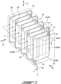
- the condenser 40 includes at least one pneumatic vessel 50 (henceforth individually referred to as “the vessel 50"), a supply conduit 46 and a drainage conduit 48 ( Figs. 2 , 4 ).
- the vessel 50 has a vessel inlet 52 for receiving the vapor from the supply conduit 46, a vessel outlet 54 for rejecting the condensate into the drainage conduit 48, and defines an interior cavity 50A (hereinafter simply “cavity”) in fluid communication between the vessel inlet and outlet 52, 54 for condensating the vapor into the condensate.
- the vessel inlet 52 and outlet 54 are respectively in fluid communication with the condenser inlet 42 and outlet 44.
- the vessel 50 is one of a plurality of vessels 50, including seven vessels 50 in the embodiment of Figs. 2 to 5 , and four vessels 50 in the embodiment of Fig. 6 .
- the vessels 50 are in fluid communication with one another via the supply and drainage conduits 46, 48 of the condenser 40.
- the supply conduit 46 is in fluid communication between the condenser inlet 42 and the vessel inlets 52 of the vessels 50
- the drainage conduit 48 is in fluid communication between the vessel outlets 54 of the vessels 50 and the condenser outlet 44.
- the supply conduit 46 and the drainage conduit 48 may respectively form part of a supply manifold and a drainage manifold of the condenser 40.
- the supply and drainage conduits 46, 48 may respectively form part of the first and second conduits 12, 14.
- the vessel 50 is inflatable.
- the cavity 50A has a volume that is variable depending on an effective pressure it is subjected to, that is, a difference between an internal pressure exerted on the vessel 50 from within the cavity 50A, and an external pressure exerted on the vessel 50 from outside the cavity 50A.
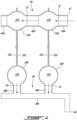
- the vessel 50 is configurable between a collapsed vessel configuration C ( Fig. 5 ) and an inflated vessel configuration I ( Figs. 2-5 ).
- the vessel 50 may be in the collapsed vessel configuration C for example upon the effective pressure being negative (i.e., upon a suction being exerted into the cavity 50A) or negligible, for example below about 200 Pa, i.e., about 0.03 pounds/sq. inch (psi).
- the vessel 50 may be in the inflated vessel configuration when the effective pressure is of at least a nominal pressure.
- the nominal pressure may correspond to a pressure at which the evaporator 30 supplies the vapor under certain operating conditions of the powerplant 1.
- the vessel 50 is structured and arranged so as to be in the inflated vessel configuration I while being able to withstand an effective pressure of about 137,895 Pa, i.e., about 20 psi.
- the vessel 50 may be structured and arranged so as to be in the inflated vessel configuration I under a relatively low effective pressure. In some embodiments, the vessel 50 may also be structured and arranged to be able to withstand a maximum effective pressure relatively close to the nominal pressure so as to minimize weight.
- the vessel 50 may be said to have a plate-like shape, meaning that the vessel 50 may be disposed in a deployed position so as to lay flat and thereby define a notional plane P ( Fig. 5 ).
- the vessel 50 In the collapsed vessel configuration C, the vessel 50 is flexible, at least to some degree, such that it may bend, buckle or otherwise deform under external loads so as to be in various positions other than the deployed position.
- the vessel 50 In the inflated vessel configuration I, the vessel 50 is comparatively more rigid and tends to resist external loads so as to remain in the deployed position.
- the condenser 40 may include a support structure 60 ( Figs. 2 , 6 ) that is suitable for holding the vessel 50 in the deployed position regardless of the vessel 50 being in the collapsed vessel configuration C or the inflated vessel configuration I.
- the support structure 60 may hold the vessels 50 in an arrayed position, i.e., at a distance from one another in a given direction, henceforth referred to as an array orientation O A , so as to form an array of vessels 50.
- the arrayed position corresponds to a spatial arrangement of the vessels 50 in which a flow path F for cooling air to flow through is defined between any two consecutive vessels 50 of the plurality of vessels 50.
- Such flow paths F extend in an orientation transverse to the array orientation O A , henceforth referred to as a path orientation O P .
- Each flow path F may be said to extend widthwise in the array orientation O A from a first one of the planes P defined by the consecutive vessels 50 to a second, opposite one of the planes P, thereby defining a width W of the flow path F.
- a size of the vessels 50 in the array orientation O A is greater in the inflated vessel configuration I than in the collapsed vessel configuration C.
- the vessels 50 may have an inflated thickness T I when in the inflated vessel configuration and a comparatively smaller collapsed thickness T C when in the collapsed vessel configuration C.
- the support structure 60 is omitted, and the vessel 50 is arranged to be self-supporting (or free-standing). In some such embodiments, inflating the vessel 50 from the collapsed vessel configuration C to the inflated vessel configuration I urges the vessel 50 into the deployed position. In embodiments in which the condenser 40 includes a plurality of self-supporting vessels 50, inflation of the vessels 50 urges the vessels 50 individually in their respective deployed position and collectively in the arrayed position.
- the vessels 50 include a frame-like structure of tubular portions 56, 58 fluidly connected to one another and together defining the cavity 50A.
- the tubular portions 56, 58 include header portions 56, namely top and bottom portions 56A, 56B spaced from one another along a transverse orientation O T that is orthogonal to the array O A and path O P orientations so as to be proximate to the condenser inlet 42 and the condenser outlet 44, respectively.
- the top portion 56A and the bottom portion 56B respectively define the vessel inlet 52 and the vessel outlet 54.
- the tubular portions 56, 58 also include at least one transverse portion 58, and in this case three, that extend transversely to the top and bottom portions 56A, 56B and are fluidly connected therebetween.
- the transverse portions 58 include first and second lateral transverse portions 58A, 58B respectively located proximate to the vessel inlet 52 and to the vessel outlet 54, and an interior transverse portion 58C disposed therebetween.
- the transverse portions 58 are spaced from one another along the path orientation O P . Between a pair of consecutive transverse portions 58 of a same vessel 50, partitions 50B the vessel 50 extend along the path orientation O P so as to separate consecutive flow paths F from one another. In certain embodiments, the partitions 50B may omitted.
- the top portions 56A of the vessels 50 may be said to form part of the supply manifold with the supply conduit 46.
- the supply conduit 46 in this case is formed of a plurality of conduit segments 46A fluidly interconnecting the condenser inlet 42 and the top portions 56A via the corresponding vessel inlets 52.
- the bottom portions 56B of the vessels 50 may be said to form part of the drainage manifold with the drainage conduit 48.
- the drainage conduit 48 in this case includes an external conduit portion 48A in fluid communication with the condenser outlet 44, and a plurality of connecting conduit portions 48B in fluid communication between the external conduit portion 48A and the bottom portions 56B of the vessels 50.
- the supply conduit 46 may instead include an external conduit portion and a plurality of connecting conduit portions similarly, mutatis mutandis, to the depicted arrangement of the drainage conduit 48.
- the drainage conduit 48 may instead be formed of a plurality of conduit segments interconnecting the condenser outlet 44 and the bottom portions 56B via the corresponding vessel outlets 54 similarly, mutatis mutandis, to the depicted arrangement of the supply conduit 46.
- the vessels 50 are disposed next to one another such that their respective transverse portions 58 are disposed in a staggered relationship in the path orientation O P .
- a first, a second and a third vessel 50', 50", 50′′′ are disposed consecutively next to one another in the array orientation O A .
- the first, second and third vessels 50', 50", 50′′′ respectively have first 58A', 58A", 58A′′′ and second 58B', 58B", 58B′′′ lateral transverse portions, and at least one interior transverse portion 58C', 58C", 58C'".
- the staggered relationship may limit, and in some cases avoid, occurrences of spans of the flow path F in the path orientation O P having no contact with any transverse portion 58 of any vessel 50.
- the second vessel 50" has an additional interior transverse portion 58C", for a total of four transverse portions 58, compared to the first and third vessels 50', 50", respectively having a total of three transverse portions 58.
- first 58A', 58A′′′ and second 58B', 58B′′′ lateral transverse portions of the first and third vessels 50', 50′′′ are offset outwardly relative to the first 58A" and second 58B" lateral transverse portions of the second vessel 50".
- the vessels 50 may have a same amount of transverse portions 58 and nonetheless be disposed in a suitable staggered relationship.
- the tubular portions 56, 58 extend generally linearly, and the top and bottom portions 56A, 56B are connected perpendicularly to the transverse portions 58, although other arrangements are contemplated, some of which including arcuate tubular portions and/or portions interconnected at other angles.
- the vessels 50 may even include a loop-like tubular structure that defines the cavity 50A instead of the member-like tubular portions 56, 58.
- the vessel 50 may be constructed of film sheets 50C ( Fig. 4 ) welded to one another.
- a pair of film sheets 50C may be used, or alternately more film sheets as required.
- Each film sheet 50C may be made of one or more layer of a suitable material, for example a layer of biaxially-oriented polyethylene terephthalate (BoPET), which may be metallized, i.e., combined with a metallic layer.
- suitable materials include metallic films and composite films, among others, which may be used alone or in combination depending on the embodiment.
- the materials may be selected and sized so as to obtain flexible film sheets 50C that are sufficiently flexible, lightweight, conductive and resistant so as to withstand maximum operational temperatures (for example a temperature close to a boiling point of the cooling fluid, e.g., 100 C in the case of water) and effective pressures (for example 137,895 Pa as stated above)of the heat exchanger 10.
- Various assembly means may be used to assemble the vessels 50 to one another via the supply and drainage conduits 46, 48.
- either one or both of the supply and drainage conduits 46, 48 may be constructed of film sheets of a same or similar construction to that of the vessels 50, and may thus be welded thereto.
- the condenser 40 may be said to be fully inflatable.
- either one or both of the supply and drainage conduits 46, 48 may include tubing that is more rigid than the vessels 50, so that such tubing retains its shape regardless of the vessels 50 being in the collapsed vessel configuration C or in the inflated vessel configuration I.
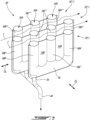
- the support structure 60 of the condenser 40 is inflatable.
- the support structure 60 in this case includes a plurality of tubular members 62, 64, 66 fluidly interconnected so as to form an inflatable rack-like structure sized for receiving the vessels 50 of the condenser 40.
- the tubular members 62, 64, 66 include two pairs of first members 62 oriented along a transverse orientation O T that is transverse to the array orientation O A and to the path orientation O P , two pairs of second members 64 oriented along the path orientation O P , and two pairs of third members 66 oriented along the array orientation O A .
- the first members 62 of a same pair are spaced from one another in the path orientation O P .
- the second members 64 of a same pair are spaced from one another in the array orientation O A .
- the third members 66 of a same pair are spaced from one another in the transverse orientation O T .
- the vessels 50 are held in place relative to the support structure 60 via welding of their respective header portions 56 to the third members 66 of the support structure 60. Welding of the vessels 50 to the support structure 60 may also be made at other locations.
- the tubular members 62, 64 and 66 are not in fluid communication with the vessels 50, such that the vessels 50 and the support structure 60 may be inflated independently.
- the support structure 60 in this case is inflated with helium, although other inflation fluids are contemplated.
- the inflation fluid may be inflammable, which may contribute to fire containment in case of an accidental leakage.
- the support structure 60 is provided with fixation means for affixing the support structure 60 to a carcass 2 of the powerplant 1 on the inside of an air cavity defined by the carcass 2 and through which the cooling airflows along a cavity orientation O C defined by the carcass 2.
- the fixation means may be for example fastening tabs 68 joined to the tubular members 62, 64, 66 on a side of the support structure 60 that is to be laid proximate to the carcass 2.
- the support structure 60 may be oriented relative to the carcass 2 and thus orient the vessels 50 relative to the air cavity such that the path orientation O P aligns with the cavity orientation O C .
- the header portions 56 are spaced from one another in the path orientation O P
- the transverse portions 58 are spaced from one another in the transverse orientation O T .
- the support structure 60 is provided with partitions 60A arranged to close the flow paths F in the transverse orientation O T .
- the partition 60A extends between opposite second members 64 and opposite third members 66 on either side of the vessels 50. In other embodiments, the partitions 60A may be omitted.
- the air cavity may be open to the environment E of the powerplant 1 and thus be at a so-called ambient pressure.
- the air cavity may be in fluid communication between a cold air source of the powerplant 1 such as a ventilating fan and/or a dynamic air inlet, and a hot air exhaust of the powerplant 1 spaced from one another along the cavity orientation O C .
- the condenser 40 may thus be suitably positioned between the cold air source and the hot air exhaust.
- a pressure inside the support structure 60 provided that it is inflatable, typically remains greater than the ambient pressure inside the air cavity, such that the support structure 60 remains inflated.
- a pressure inside the vessels 50 may be close to the ambient pressure, such that the vessels 50 may be in the collapsed vessel configuration C whereas little cooling (e.g., cooling at less than the target cooling rate) or no cooling may occur.
- the pressure inside the vessels 50 may be greater than the ambient pressure, such that the vessels are in the inflated vessel configuration I whereas cooling may occur (e.g., cooling at at least the target cooling rate).
Landscapes
- Engineering & Computer Science (AREA)
- Mechanical Engineering (AREA)
- Physics & Mathematics (AREA)
- Thermal Sciences (AREA)
- General Engineering & Computer Science (AREA)
- Chemical & Material Sciences (AREA)
- Combustion & Propulsion (AREA)
- Aviation & Aerospace Engineering (AREA)
- Heat-Exchange Devices With Radiators And Conduit Assemblies (AREA)
Abstract
Description
- The present invention relates generally to aircraft engines and, more particularly, to heat exchanger systems for aircraft powerplants.
- Aircraft powerplants have stringent cooling requirements, some of which are typically addressed by liquid-to-air heat exchangers. In such heat exchangers, a closed-loop fluidic circuit carries a liquid coolant from the vicinity of a source of heat of the powerplant, to a heat exchanger at which the liquid coolant rejects the heat into cooling airflow(s). With the advent of hybrid powerplants in aeronautics, the quantity, locations and overall output of the sources of heat requiring cooling have evolved, which presents challenges in implementing heat exchangers that are suitable in terms of size, weight and cooling capacity.
- In accordance with an aspect of the present invention, there is provided a vapor-to-air heat exchanger for an aircraft powerplant, comprising: a pressurized vapor source supplying vapor; and a condenser including a condenser inlet in fluid communication with the pressurized vapor source to receive the vapor, a condenser outlet, and at least one pneumatic vessel defining a cavity in fluid communication between the condenser inlet and the condenser outlet, the at least one pneumatic vessel being reversibly inflatable to be configurable between a collapsed vessel configuration and an inflated vessel configuration, a volume of the cavity being greater in the inflated vessel configuration than in the collapsed vessel configuration, the at least one pneumatic vessel being inflatable from the collapsed vessel configuration to the inflated vessel configuration when the cavity is pressurized by the vapor.
- The vapor-to-air heat exchanger as defined above and described herein may further include one or more of the following features, in whole or in part, and in any combination.
- Optionally, and in accordance with the above, the at least one pneumatic vessel is formed of flexible film sheets welded to one another.
- Optionally, and in accordance with any of the above, at least one sheet of the flexible film sheets includes one or more of: a metallic layer; and a composite layer.
- Optionally, and in accordance with any of the above, the at least one pneumatic vessel includes a top tubular portion proximate to the condenser inlet, a bottom tubular portion proximate to the condenser outlet, and at least one transverse tubular portion fluidly connected between the top tubular portion and the bottom tubular portion.
- Optionally, and in accordance with any of the above, the condenser comprises a plurality of pneumatic vessels including the at least one pneumatic vessel, and the top tubular portion defines a portion of a supply manifold of the condenser.
- Optionally, and in accordance with any of the above, the condenser comprises a plurality of pneumatic vessels including the at least one pneumatic vessel, and the bottom tubular portion defines a portion of a drainage manifold of the condenser.
- Optionally, and in accordance with any of the above, the heat exchanger includes one or more of: a pressure regulating valve between the pressurized vapor source and the condenser inlet; and a pump between the condenser outlet and the pressurized vapor source.
- Optionally, and in accordance with any of the above, the heat exchanger includes a support structure attached to the at least one pneumatic vessel for holding the at least one pneumatic vessel in a deployed position.
- Optionally, and in accordance with any of the above, the support structure is configurable between a collapsed support configuration and an inflated support configuration, the support structure being inflatable from the collapsed support configuration to the inflated support configuration.
- Optionally, and in accordance with any of the above, the at least one pneumatic vessel is in the inflated vessel configuration when the cavity is pressurized by the vapor to at least a nominal pressure, the pressurized vapor source supplying the vapor at a source pressure of at least the nominal pressure.
- In accordance with another aspect of the present invention, there is provided a vapor-to-air heat exchanger for an aircraft powerplant, comprising: an evaporator supplying vapor; and a condenser including: a condenser inlet in fluid communication with the evaporator to receive vapor therefrom; a condenser outlet; and an array of pneumatic vessels spaced from one another in an array orientation so as to define at least one air flow path along a path orientation transverse to the array orientation, at least one pneumatic vessel of the array of pneumatic vessels defining an cavity, a plane transverse to the array orientation extending through the cavity, the cavity being in fluid communication between the condenser inlet and the condenser outlet, the at least one pneumatic vessel being inflatable when the cavity is pressurized by the vapor to transition from a collapsed vessel configuration to an inflated vessel configuration, a size of the at least one pneumatic vessel in the array orientation being greater in the inflated vessel configuration than in the collapsed vessel configuration.
- The vapor-to-air heat exchanger as defined above and described herein may further include one or more of the following features, in whole or in part, and in any combination.
- Optionally, and in accordance with any of the above, the at least one pneumatized vessel includes a top tubular portion proximate to the condenser inlet, a bottom tubular portion proximate to the condenser outlet, and a plurality of transverse tubular portions fluidly connected between the top and the bottom tubular portions and spaced from one another in the path orientation.
- Optionally, and in accordance with any of the above, the at least one pneumatic vessel includes a first vessel and a second vessel next to one another on either side of the at least one flow path, a first plurality of transverse tubular portions of the first vessel and a second plurality of transverse tubular portions of the second vessel being in a staggered relationship in the path orientation.
- In accordance with another aspect of the present invention, there is provided a powerplant for an aircraft, comprising: a power unit rejecting heat at a nominal heat rejection rate; and a vapor-to-air heat exchanger including: an evaporator thermally coupled to the power unit so as to supply vapor at a nominal pressure upon the power unit rejecting heat at the nominal heat rejection rate; and a condenser including a condenser inlet downstream of the evaporator, a condenser outlet, and at least one pneumatic vessel being inflatable and defining an cavity in fluid communication between the condenser inlet and the condenser outlet, the at least one pneumatic vessel being configurable between a collapsed vessel configuration and an inflated vessel configuration, the at least one pneumatic vessel being inflatable from the collapsed vessel configuration to the inflated vessel configuration upon the cavity being pressurized up to the nominal pressure.
- The powerplant as defined above and described herein may further include one or more of the following features, in whole or in part, and in any combination.
- Optionally, and in accordance with any of the above, the at least one pneumatic vessel is constructed of a pair of flexible film sheets welded to one another.
- Optionally, and in accordance with any of the above, the at least one pneumatic vessel includes a top tubular portion proximate to the condenser inlet, a bottom tubular portion proximate to the condenser outlet, and at least one transverse tubular portion fluidly connected between the top and the bottom tubular portions.
- Optionally, and in accordance with any of the above, the condenser comprises a plurality of pneumatic vessels including the at least one pneumatic vessel, and the top tubular portion defines a portion of a supply manifold of the condenser.
- Optionally, and in accordance with any of the above, the powerplant includes one or more of: a pressure regulating valve between the evaporator and the condenser inlet; and a pump between the condenser outlet and the evaporator.
- Optionally, and in accordance with any of the above, the powerplant includes a support structure supporting the at least one pneumatic vessel and a carcass defining an air cavity, the support structure affixed to the carcass so as to orient the at least one pneumatic vessel relative to the air cavity.
- Optionally, and in accordance with any of the above, the support structure is configurable between a collapsed support configuration and an inflated support configuration, the support structure being inflatable from the collapsed support configuration to the inflated support configuration.
- Reference is now made to the accompanying figures in which:
-
Fig. 1 is a schematic view of a heat exchanger for a powerplant; -
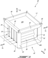
Fig. 2 is a perspective view of a condenser of the heat exchanger ofFig. 1 according to an embodiment; -
Fig. 3 is a partial cut-away view of the condenser ofFig. 2 , taken along the line 3-3 ofFig. 2 ; -
Fig. 4 is a partial cross-sectional view of the condenser ofFig. 2 , taken along the line 4-4 ofFig. 2 ; -
Fig. 5 is an elevation view of vessels of the condenser ofFig. 2 ; and -
Fig. 6 is a perspective view of a condenser of the heat exchanger ofFig. 1 according to another embodiment. - A
heat exchanger 10 is generally shown at 10, depicted onFig. 1 in a heat exchange relationship between a cooledsystem 20, or heat source, of a powerplant 1 and an environment E of the powerplant 1. The powerplant 1 may be any suitable aircraft engine, whether a gas turbine engine, a primarily electric engine, a hybrid-electric engine, or any combination of same. The cooledsystem 20 may be any component of the powerplant 1 that employ cooling. Among exemplary possibilities, the cooledsystem 20 may be a power unit of the powerplant 1, such as a fuel system in the case of a powerplant including an internal combustion engine, or a battery pack in the case of a powerplant including an electric motor. The cooling of the battery pack via theheat exchanger 10 may assist in maintaining the integrity of the battery pack as well as suitable lifespan and charging and discharging regimes. The cooledsystem 20 may also be an oil system of the powerplant 1. The cooledsystem 20 may also be a turbine case of a gas turbine engine. The cooling of the turbine case may assist in maintaining a suitable clearance with a rotor surrounded thereby. - The
heat exchanger 10 is of the closed circuit type, meaning that a cooling fluid it contains remains captive notwithstanding undesired leakage. Hence, theheat exchanger 10 allows to transfer heat to and from its cooling fluid without any variation in mass of the cooling fluid contained thereby. The cooling fluid is of a type selected to change between gaseous and liquid phases under operating conditions of the powerplant 1, namely to evaporate as it absorbs heat transferred thereto by the cooledsystem 20, and to condensate as it rejects heat to the environment E. The cooling fluid may be water, although other suitable cooling fluids may be used, such as carbon tetrachloride. Advantageously, the cooling fluid may be inflammable, which may contribute to fire containment in case of an accidental leakage. - Hence, the
heat exchanger 10 comprises anevaporator 30 thermally coupled to the cooledsystem 20 so as to absorb heat therefrom at a target cooling rate. The architecture of theevaporator 30 may vary depending on the embodiment, so long as it is suitable for circulating the cooling fluid alongside the cooledsystem 20 in a manner allowing the transfer of thermal energy from the cooledsystem 20 to the cooling fluid, causing the cooling fluid to evaporate in the process. Theheat exchanger 10 also comprises acondenser 40 remote from theevaporator 30. Fluid lines, orconduits heat exchanger 10 are routed between theevaporator 30 and thecondenser 40 to allow circulation of the cooling fluid in theheat exchanger 10. Namely, afirst conduit 12 is in fluid communication between anevaporator outlet 34 of theevaporator 30 and acondenser inlet 42 of thecondenser 40. Thecondenser inlet 42 may in some cases be a part of thefirst conduit 12. Asecond conduit 14 is in fluid communication between acondenser outlet 44 of thecondenser 40 and anevaporator inlet 32 of theevaporator 30. Thecondenser outlet 44 may in some cases be a part of thesecond conduit 14. Thecondenser 40 is disposed in the powerplant 1 so as to be exposed to a flow of air having an incoming temperature and volumetric flow rate that are suitable for convecting heat away from thecondenser 40 at a target rejection rate commensurate to the target cooling rate, and theconduits - In some embodiments, the
heat exchanger 10 includes one or more flow-regulating means 16, 18 in fluid communication between theevaporator 30 and thecondenser 40. As the cooling liquid flows through theevaporator 30, the cooling fluid evaporates into the gaseous phase (i.e., into vapor) and in doing so, causes a pressure increase across theevaporator 30, i.e., an evaporator inlet pressure at theevaporator inlet 32 is less than an evaporator outlet pressure at theevaporator outlet 34. Theevaporator 30 may thus be referred to as a pressurized vapor source. In some embodiments, theheat exchanger 10 includes apressure regulating valve 16 in fluid communication with thefirst conduit 12 between theevaporator 30 and thecondenser inlet 42. Thepressure regulating valve 16 may be a laminar flow valve. Thevalve 16 may assist in conveying the vapor to thecondenser 40 at a flow rate and a pressure commensurate to the capacity of thecondenser 40. As the cooling fluid flows through thecondenser 40, the cooling fluid condensates into the liquid phase (i.e., into condensate) and in doing so, causes a pressure drop across thecondenser 40, i.e., a condenser inlet pressure at thecondenser inlet 42 is greater than a condenser outlet pressure at thecondenser outlet 44. In this embodiment, theheat exchanger 10 includes apump 18 disposed in fluid communication with thesecond conduit 14 between thecondenser outlet 44 and theevaporator 30. Thepump 18 may assist in conveying the condensate to theevaporator 30 at a flow rate and a pressure commensurate to the capacity of theevaporator 30. - In some embodiments, the
condenser 40 may be sized and arranged so as to accept the cooling fluid in the flow conditions outputted at theevaporator outlet 34 and perform at the target rejection rate, such that thevalve 16 may be omitted. In some embodiments, theevaporator 30 may be sized and arranged so as to accept the cooling fluid in the flow conditions outputted at thecondenser outlet 44 and perform at the target cooling rate, such that thepump 18 may be omitted. Stated otherwise, in some embodiments, theheat exchanger 10 may be oversized in view of the target cooling rate such that the flow-regulating means (e.g., thevalve 16 and/or the pump 18) may be omitted. Oversizing theheat exchanger 10 may mean oversizing a size of thecondenser 40 relative to a size of theevaporator 30 such that thecondenser 40 is capable of condensating more vapor than the evaporator 30 can produce. The size of thecondenser 40 may correspond to a surface area of thecondenser 40 forming an outbound heat transfer interface between the cooling fluid and the flow of air. The size of theevaporator 30 may correspond to a surface area of theevaporator 30 forming an inbound heat transfer interface between the cooledsystem 20 and the cooling fluid. Oversizing theheat exchanger 10 may render a nominal heat rejection rate of thecondenser 40 greater than the target cooling rate. - With reference to
Figs. 2-6 , thecondenser 40 will now be described in more detail. Thecondenser 40 includes at least one pneumatic vessel 50 (henceforth individually referred to as "thevessel 50"), asupply conduit 46 and a drainage conduit 48 (Figs. 2 ,4 ). As seen inFigs. 3 and4 , thevessel 50 has avessel inlet 52 for receiving the vapor from thesupply conduit 46, avessel outlet 54 for rejecting the condensate into thedrainage conduit 48, and defines aninterior cavity 50A (hereinafter simply "cavity") in fluid communication between the vessel inlet andoutlet vessel inlet 52 andoutlet 54 are respectively in fluid communication with thecondenser inlet 42 andoutlet 44. In the depicted embodiments, thevessel 50 is one of a plurality ofvessels 50, including sevenvessels 50 in the embodiment ofFigs. 2 to 5 , and fourvessels 50 in the embodiment ofFig. 6 . In either embodiment, thevessels 50 are in fluid communication with one another via the supply anddrainage conduits condenser 40. Thesupply conduit 46 is in fluid communication between thecondenser inlet 42 and thevessel inlets 52 of thevessels 50, whereas thedrainage conduit 48 is in fluid communication between thevessel outlets 54 of thevessels 50 and thecondenser outlet 44. Hence, in embodiments having a plurality ofvessels 50, thesupply conduit 46 and thedrainage conduit 48 may respectively form part of a supply manifold and a drainage manifold of thecondenser 40. In embodiments having asole vessel 50, the supply anddrainage conduits second conduits - As the "pneumatic" qualifier implies, the
vessel 50 is inflatable. Thecavity 50A has a volume that is variable depending on an effective pressure it is subjected to, that is, a difference between an internal pressure exerted on thevessel 50 from within thecavity 50A, and an external pressure exerted on thevessel 50 from outside thecavity 50A. By varying its degree of inflation, thevessel 50 is configurable between a collapsed vessel configuration C (Fig. 5 ) and an inflated vessel configuration I (Figs. 2-5 ). - The
vessel 50 may be in the collapsed vessel configuration C for example upon the effective pressure being negative (i.e., upon a suction being exerted into thecavity 50A) or negligible, for example below about 200 Pa, i.e., about 0.03 pounds/sq. inch (psi). Thevessel 50 may be in the inflated vessel configuration when the effective pressure is of at least a nominal pressure. The nominal pressure may correspond to a pressure at which theevaporator 30 supplies the vapor under certain operating conditions of the powerplant 1. In the depicted embodiment, thevessel 50 is structured and arranged so as to be in the inflated vessel configuration I while being able to withstand an effective pressure of about 137,895 Pa, i.e., about 20 psi. In some embodiments, thevessel 50 may be structured and arranged so as to be in the inflated vessel configuration I under a relatively low effective pressure. In some embodiments, thevessel 50 may also be structured and arranged to be able to withstand a maximum effective pressure relatively close to the nominal pressure so as to minimize weight. - The
vessel 50 may be said to have a plate-like shape, meaning that thevessel 50 may be disposed in a deployed position so as to lay flat and thereby define a notional plane P (Fig. 5 ). In the collapsed vessel configuration C, thevessel 50 is flexible, at least to some degree, such that it may bend, buckle or otherwise deform under external loads so as to be in various positions other than the deployed position. In the inflated vessel configuration I, thevessel 50 is comparatively more rigid and tends to resist external loads so as to remain in the deployed position. - Depending on the embodiment, the
condenser 40 may include a support structure 60 (Figs. 2 ,6 ) that is suitable for holding thevessel 50 in the deployed position regardless of thevessel 50 being in the collapsed vessel configuration C or the inflated vessel configuration I. In embodiments in which a plurality ofvessels 50 are provided, thesupport structure 60 may hold thevessels 50 in an arrayed position, i.e., at a distance from one another in a given direction, henceforth referred to as an array orientation OA, so as to form an array ofvessels 50. The arrayed position corresponds to a spatial arrangement of thevessels 50 in which a flow path F for cooling air to flow through is defined between any twoconsecutive vessels 50 of the plurality ofvessels 50. Such flow paths F extend in an orientation transverse to the array orientation OA, henceforth referred to as a path orientation OP. Each flow path F may be said to extend widthwise in the array orientation OA from a first one of the planes P defined by theconsecutive vessels 50 to a second, opposite one of the planes P, thereby defining a width W of the flow path F. As schematically depicted inFig. 5 , when thevessels 50 are held in the arrayed position, a size of thevessels 50 in the array orientation OA is greater in the inflated vessel configuration I than in the collapsed vessel configuration C. Stated otherwise, thevessels 50 may have an inflated thickness TI when in the inflated vessel configuration and a comparatively smaller collapsed thickness TC when in the collapsed vessel configuration C. By increasing the size of thevessels 50 in the array orientation OA so as to impinge on the flow paths F, a surface area of thecondenser 40 exposed to the cooling air, and thus a capacity of thecondenser 40, may increase. - In some other embodiments, the
support structure 60 is omitted, and thevessel 50 is arranged to be self-supporting (or free-standing). In some such embodiments, inflating thevessel 50 from the collapsed vessel configuration C to the inflated vessel configuration I urges thevessel 50 into the deployed position. In embodiments in which thecondenser 40 includes a plurality of self-supportingvessels 50, inflation of thevessels 50 urges thevessels 50 individually in their respective deployed position and collectively in the arrayed position. - With reference to
Fig. 2-4 , structural characteristics of thecondenser 40 will be discussed. In this embodiment, thevessels 50 include a frame-like structure oftubular portions cavity 50A. Thetubular portions header portions 56, namely top andbottom portions condenser inlet 42 and thecondenser outlet 44, respectively. Thetop portion 56A and thebottom portion 56B respectively define thevessel inlet 52 and thevessel outlet 54. Thetubular portions transverse portion 58, and in this case three, that extend transversely to the top andbottom portions transverse portions 58 include first and second lateraltransverse portions vessel inlet 52 and to thevessel outlet 54, and an interiortransverse portion 58C disposed therebetween. Thetransverse portions 58 are spaced from one another along the path orientation OP. Between a pair of consecutivetransverse portions 58 of asame vessel 50,partitions 50B thevessel 50 extend along the path orientation OP so as to separate consecutive flow paths F from one another. In certain embodiments, thepartitions 50B may omitted. Thetop portions 56A of thevessels 50 may be said to form part of the supply manifold with thesupply conduit 46. Thesupply conduit 46 in this case is formed of a plurality ofconduit segments 46A fluidly interconnecting thecondenser inlet 42 and thetop portions 56A via the correspondingvessel inlets 52. Thebottom portions 56B of thevessels 50 may be said to form part of the drainage manifold with thedrainage conduit 48. Thedrainage conduit 48 in this case includes anexternal conduit portion 48A in fluid communication with thecondenser outlet 44, and a plurality of connectingconduit portions 48B in fluid communication between theexternal conduit portion 48A and thebottom portions 56B of thevessels 50. In alternate embodiments, thesupply conduit 46 may instead include an external conduit portion and a plurality of connecting conduit portions similarly, mutatis mutandis, to the depicted arrangement of thedrainage conduit 48. Thedrainage conduit 48 may instead be formed of a plurality of conduit segments interconnecting thecondenser outlet 44 and thebottom portions 56B via the correspondingvessel outlets 54 similarly, mutatis mutandis, to the depicted arrangement of thesupply conduit 46. - It should be noted that the
vessels 50 are disposed next to one another such that their respectivetransverse portions 58 are disposed in a staggered relationship in the path orientation OP. Referring toFig. 3 for example, a first, a second and athird vessel 50', 50", 50‴ are disposed consecutively next to one another in the array orientation OA. The first, second andthird vessels 50', 50", 50‴ respectively have first 58A', 58A", 58A‴ and second 58B', 58B", 58B‴ lateral transverse portions, and at least one interiortransverse portion 58C', 58C", 58C'". The first lateraltransverse portion 58A' of the first vessel 50' and the first lateraltransverse portion 58A‴ of thethird vessel 50‴ face one another on either side of thesecond vessel 50", albeit at an offset in the path orientation OP relative to the first lateraltransverse portion 50A" of thesecond vessel 50". The staggered relationship may limit, and in some cases avoid, occurrences of spans of the flow path F in the path orientation OP having no contact with anytransverse portion 58 of anyvessel 50. It should be noted that thesecond vessel 50" has an additional interiortransverse portion 58C", for a total of fourtransverse portions 58, compared to the first andthird vessels 50', 50", respectively having a total of threetransverse portions 58. As such, the first 58A', 58A‴ and second 58B', 58B‴ lateral transverse portions of the first andthird vessels 50', 50‴ are offset outwardly relative to the first 58A" and second 58B" lateral transverse portions of thesecond vessel 50". In other embodiments, thevessels 50 may have a same amount oftransverse portions 58 and nonetheless be disposed in a suitable staggered relationship. - In the depicted embodiments, the
tubular portions bottom portions transverse portions 58, although other arrangements are contemplated, some of which including arcuate tubular portions and/or portions interconnected at other angles. For example, in other embodiments, thevessels 50 may even include a loop-like tubular structure that defines thecavity 50A instead of the member-liketubular portions - In embodiments, the
vessel 50 may be constructed offilm sheets 50C (Fig. 4 ) welded to one another. For example, a pair offilm sheets 50C may be used, or alternately more film sheets as required. Eachfilm sheet 50C may be made of one or more layer of a suitable material, for example a layer of biaxially-oriented polyethylene terephthalate (BoPET), which may be metallized, i.e., combined with a metallic layer. Other suitable materials include metallic films and composite films, among others, which may be used alone or in combination depending on the embodiment. The materials may be selected and sized so as to obtainflexible film sheets 50C that are sufficiently flexible, lightweight, conductive and resistant so as to withstand maximum operational temperatures (for example a temperature close to a boiling point of the cooling fluid, e.g., 100 C in the case of water) and effective pressures (for example 137,895 Pa as stated above)of theheat exchanger 10. Various assembly means may be used to assemble thevessels 50 to one another via the supply anddrainage conduits drainage conduits vessels 50, and may thus be welded thereto. In some such embodiments, thecondenser 40 may be said to be fully inflatable. In other embodiments, either one or both of the supply anddrainage conduits vessels 50, so that such tubing retains its shape regardless of thevessels 50 being in the collapsed vessel configuration C or in the inflated vessel configuration I. - Turning now to
Fig. 6 , there is shown another embodiment in which thesupport structure 60 of thecondenser 40 is inflatable. Thesupport structure 60 in this case includes a plurality oftubular members vessels 50 of thecondenser 40. Thetubular members first members 62 oriented along a transverse orientation OT that is transverse to the array orientation OA and to the path orientation OP, two pairs ofsecond members 64 oriented along the path orientation OP, and two pairs ofthird members 66 oriented along the array orientation OA. Thefirst members 62 of a same pair are spaced from one another in the path orientation OP. Thesecond members 64 of a same pair are spaced from one another in the array orientation OA. Thethird members 66 of a same pair are spaced from one another in the transverse orientation OT. In this embodiment, thevessels 50 are held in place relative to thesupport structure 60 via welding of theirrespective header portions 56 to thethird members 66 of thesupport structure 60. Welding of thevessels 50 to thesupport structure 60 may also be made at other locations. It shall be noted however that thetubular members vessels 50, such that thevessels 50 and thesupport structure 60 may be inflated independently. Thesupport structure 60 in this case is inflated with helium, although other inflation fluids are contemplated. Advantageously, the inflation fluid may be inflammable, which may contribute to fire containment in case of an accidental leakage. - The
support structure 60 is provided with fixation means for affixing thesupport structure 60 to acarcass 2 of the powerplant 1 on the inside of an air cavity defined by thecarcass 2 and through which the cooling airflows along a cavity orientation OC defined by thecarcass 2. The fixation means may be forexample fastening tabs 68 joined to thetubular members support structure 60 that is to be laid proximate to thecarcass 2. By way of the fixation means, thesupport structure 60 may be oriented relative to thecarcass 2 and thus orient thevessels 50 relative to the air cavity such that the path orientation OP aligns with the cavity orientation OC. - In the depicted embodiment, the
header portions 56 are spaced from one another in the path orientation OP, and thetransverse portions 58 are spaced from one another in the transverse orientation OT. Thesupport structure 60 is provided withpartitions 60A arranged to close the flow paths F in the transverse orientation OT. Thepartition 60A extends between oppositesecond members 64 and oppositethird members 66 on either side of thevessels 50. In other embodiments, thepartitions 60A may be omitted. - The air cavity may be open to the environment E of the powerplant 1 and thus be at a so-called ambient pressure. The air cavity may be in fluid communication between a cold air source of the powerplant 1 such as a ventilating fan and/or a dynamic air inlet, and a hot air exhaust of the powerplant 1 spaced from one another along the cavity orientation OC. The
condenser 40 may thus be suitably positioned between the cold air source and the hot air exhaust. In use, a pressure inside thesupport structure 60, provided that it is inflatable, typically remains greater than the ambient pressure inside the air cavity, such that thesupport structure 60 remains inflated. When theevaporator 30 produces little or no vapor (such that the effective pressure is less than 200 Pa for example), a pressure inside thevessels 50 may be close to the ambient pressure, such that thevessels 50 may be in the collapsed vessel configuration C whereas little cooling (e.g., cooling at less than the target cooling rate) or no cooling may occur. When theevaporator 30 produces sufficient vapor (such that the effective pressure is of at least 200 Pa for example), the pressure inside thevessels 50 may be greater than the ambient pressure, such that the vessels are in the inflated vessel configuration I whereas cooling may occur (e.g., cooling at at least the target cooling rate). - The embodiments described in this document provide non-limiting examples of possible implementations of the present technology. Upon review of the present disclosure, a person of ordinary skill in the art will recognize that changes may be made to the embodiments described herein without departing from the scope of the present technology. Further modifications could be implemented by a person of ordinary skill in the art in view of the present disclosure, which modifications would be within the scope of the present technology.
Claims (15)
- A vapor-to-air heat exchanger (10) for an aircraft powerplant (1), comprising:a pressurized vapor source (30) supplying vapor; anda condenser (40) including a condenser inlet (42) in fluid communication with the pressurized vapor source (30) to receive the vapor, a condenser outlet (44), and a pneumatic vessel (50) defining a cavity (50A) in fluid communication between the condenser inlet (42) and the condenser outlet (44), the pneumatic vessel (50) being reversibly inflatable to be configurable between a collapsed vessel (C) configuration and an inflated vessel (I) configuration, a volume of the cavity (50A) being greater in the inflated vessel (I) configuration than in the collapsed vessel (C) configuration, the pneumatic vessel (50) being inflatable from the collapsed vessel (C) configuration to the inflated vessel (I) configuration when the cavity (50A) is pressurized by the vapor.
- The vapor-to-air heat exchanger (10) of claim 1, wherein the pneumatic vessel (50) is formed of flexible film sheets (50C) welded to one another.
- The vapor-to-air heat exchanger (10) of claim 2, wherein at least one sheet of the flexible film sheets (50C) includes one or more of: a metallic layer; and a composite layer.
- The vapor-to-air heat exchanger (10) of any preceding claim, wherein the pneumatic vessel (50) includes a top tubular portion (56A) proximate to the condenser inlet (42), a bottom tubular portion (56B) proximate to the condenser outlet (44), and at least one transverse tubular portion (58) fluidly connected between the top tubular portion (56A) and the bottom tubular portion (56B).
- The vapor-to-air heat exchanger (10) of claim 4, wherein the condenser (40) comprises a plurality of pneumatic vessels (50) including the pneumatic vessel (50), and wherein the top tubular portion (56A) defines a portion of a supply manifold of the condenser (40) and/or the bottom tubular portion (56B) defines a portion of a drainage manifold of the condenser (40).
- The vapor-to-air heat exchanger (10) of any preceding claim, further comprising a pressure regulating valve (16) between the pressurized vapor source (30) and the condenser inlet (42), and/or a pump (18) between the condenser outlet (44) and the pressurized vapor source (30).
- The vapor-to-air heat exchanger (10) of any preceding claim, further comprising a support structure (60) attached to the pneumatic vessel (50) for holding the pneumatic vessel (50) in a deployed position, the support structure (60) optionally being configurable between a collapsed support configuration and an inflated support configuration, the support structure (60) being inflatable from the collapsed support configuration to the inflated support configuration.
- The vapor-to-air heat exchanger (10) of any preceding claim, wherein the pneumatic vessel (50) is in the inflated vessel (I) configuration when the cavity (50A) is pressurized by the vapor to at least a nominal pressure, the pressurized vapor source (30) supplying the vapor at a source pressure of at least the nominal pressure.
- The vapor-to-air heat exchanger (10) of any preceding claim, wherein the pneumatic vessel (50) is one pneumatic vessel (50) within an array of pneumatic vessels (50) spaced from one another in an array orientation (OA) so as to define at least one air flow path along a path orientation (OP) transverse to the array orientation, a plane transverse to the array orientation (OA) extending through the cavity (50A) of the pneumatic vessel (50).
- A powerplant (1) for an aircraft, comprising:a power unit (20) rejecting heat at a nominal heat rejection rate; anda vapor-to-air heat exchanger (10) including:an evaporator (30) thermally coupled to the power unit (20) so as to supply vapor at a nominal pressure upon the power unit (20) rejecting heat at the nominal heat rejection rate; anda condenser (40) including a condenser inlet (42) downstream of the evaporator (30), a condenser outlet (44), and at least one pneumatic vessel (50) being inflatable and defining an cavity (50A) in fluid communication between the condenser inlet (42) and the condenser outlet (44), the at least one pneumatic vessel (50) being configurable between a collapsed vessel configuration (C) and an inflated vessel configuration (I), the at least one pneumatic vessel (50) being inflatable from the collapsed vessel configuration (c) to the inflated vessel configuration (I) upon the cavity (50A) being pressurized up to the nominal pressure.
- The powerplant (1) of claim 10, wherein the at least one pneumatic vessel (50) is constructed of a pair of flexible film sheets (50C) welded to one another.
- The powerplant (1) of claim 10 or 11, wherein the at least one pneumatic vessel (50) includes a top tubular portion (56A) proximate to the condenser inlet (42), a bottom tubular portion (56B) proximate to the condenser outlet (44), and at least one transverse tubular portion (58) fluidly connected between the top (56A) and the bottom (56B) tubular portions.
- The powerplant (1) of claim 12, wherein the condenser (40) comprises a plurality of pneumatic vessels (50) including the at least one pneumatic vessel (50), and the top tubular portion (56A) defines a portion of a supply manifold of the condenser (40).
- The powerplant (1) of any of claims 10 to 13, further comprising a pressure regulating valve (16) between the evaporator (30) and the condenser inlet (42), and/or a pump (18) between the condenser outlet (44) and the evaporator (30).
- The powerplant (1) of any of claims 10 to 14, further comprising a support structure (60) supporting the at least one pneumatic vessel (50) and a carcass (2) defining an air cavity (50A), the support structure (60) affixed to the carcass (2) so as to orient the at least one pneumatic vessel (50) relative to the air cavity (50A), the support structure (60) optionally being configurable between a collapsed support configuration and an inflated support configuration, the support structure (60) being inflatable from the collapsed support configuration to the inflated support configuration.
Applications Claiming Priority (1)
| Application Number | Priority Date | Filing Date | Title |
|---|---|---|---|
| US17/669,536 US11945598B2 (en) | 2022-02-11 | 2022-02-11 | Vapor-to-air heat exchanger for aircraft powerplant |
Publications (2)
| Publication Number | Publication Date |
|---|---|
| EP4227609A1 true EP4227609A1 (en) | 2023-08-16 |
| EP4227609B1 EP4227609B1 (en) | 2024-08-28 |
Family
ID=85227065
Family Applications (1)
| Application Number | Title | Priority Date | Filing Date |
|---|---|---|---|
| EP23156378.4A Active EP4227609B1 (en) | 2022-02-11 | 2023-02-13 | Vapor-to-air heat exchanger for aircraft powerplant |
Country Status (3)
| Country | Link |
|---|---|
| US (1) | US11945598B2 (en) |
| EP (1) | EP4227609B1 (en) |
| CA (1) | CA3186822A1 (en) |
Citations (4)
| Publication number | Priority date | Publication date | Assignee | Title |
|---|---|---|---|---|
| FR2112006A1 (en) * | 1970-04-01 | 1972-06-16 | Velut Rene | Surface heat exchanger - comprises flexible flat pockets between rigid flat plates |
| DE3242531A1 (en) * | 1982-11-18 | 1984-05-24 | Dietmar 2120 Lüneburg Köller | Heat exchangers and method of de-icing the same |
| US5927383A (en) * | 1995-10-03 | 1999-07-27 | Hadwaco Ltd Oy | Heat exchanger and a method for producing the same |
| US20190049156A1 (en) * | 2013-03-14 | 2019-02-14 | Rolls-Royce Corporation | Thermal management system controlling dynamic and steady state thermal loads |
Family Cites Families (6)
| Publication number | Priority date | Publication date | Assignee | Title |
|---|---|---|---|---|
| US4305456A (en) | 1977-08-12 | 1981-12-15 | Paul Mueller Company | Condenser and hot water system |
| US4484623A (en) | 1983-04-08 | 1984-11-27 | Paul Mueller Company | Dual flow condenser with through connections |
| US6892797B2 (en) | 2001-12-21 | 2005-05-17 | Honeywell International, Inc. | Heat exchanger with biased and expandable core support structure |
| US7178585B1 (en) * | 2005-08-04 | 2007-02-20 | Delphi Technologies, Inc. | Hybrid evaporator |
| DE102015215063A1 (en) * | 2015-08-06 | 2017-02-09 | Mahle International Gmbh | Container for a waste heat recovery cycle |
| US10842044B2 (en) * | 2017-07-10 | 2020-11-17 | Rolls-Royce North American Technologies, Inc. | Cooling system in hybrid electric propulsion gas turbine engine |
-
2022
- 2022-02-11 US US17/669,536 patent/US11945598B2/en active Active
-
2023
- 2023-01-11 CA CA3186822A patent/CA3186822A1/en active Pending
- 2023-02-13 EP EP23156378.4A patent/EP4227609B1/en active Active
Patent Citations (4)
| Publication number | Priority date | Publication date | Assignee | Title |
|---|---|---|---|---|
| FR2112006A1 (en) * | 1970-04-01 | 1972-06-16 | Velut Rene | Surface heat exchanger - comprises flexible flat pockets between rigid flat plates |
| DE3242531A1 (en) * | 1982-11-18 | 1984-05-24 | Dietmar 2120 Lüneburg Köller | Heat exchangers and method of de-icing the same |
| US5927383A (en) * | 1995-10-03 | 1999-07-27 | Hadwaco Ltd Oy | Heat exchanger and a method for producing the same |
| US20190049156A1 (en) * | 2013-03-14 | 2019-02-14 | Rolls-Royce Corporation | Thermal management system controlling dynamic and steady state thermal loads |
Also Published As
| Publication number | Publication date |
|---|---|
| US11945598B2 (en) | 2024-04-02 |
| CA3186822A1 (en) | 2023-08-11 |
| US20230257133A1 (en) | 2023-08-17 |
| EP4227609B1 (en) | 2024-08-28 |
Similar Documents
| Publication | Publication Date | Title |
|---|---|---|
| US20240167769A1 (en) | Integrated cooling module | |
| US20080110603A1 (en) | Integrated heat exchangers for ecs and obiggs applications | |
| US11326839B2 (en) | Thermal exchanger-accumulator | |
| US10011362B2 (en) | Aircraft outer skin heat exchanger, aircraft cooling system and method for operating an aircraft outer skin heat exchanger | |
| EP3419843A1 (en) | Vehicle thermal management system and heat exchangers | |
| US12497188B2 (en) | Liquid hydrogen feed system for fuel cell powered aircraft | |
| EP4509398A1 (en) | Fuel cell aircraft thermal management system | |
| US9698435B2 (en) | System and method for cooling an aircraft fuel cell system | |
| JP2022168719A (en) | Air vehicle | |
| EP4509409A1 (en) | Nacelle air heat exchanger integration for a hydrogen fueled fuel cell powered aircraft | |
| US11384990B2 (en) | Prime surface heat exchanger with contoured separator members | |
| EP4227609B1 (en) | Vapor-to-air heat exchanger for aircraft powerplant | |
| EP3546257B1 (en) | Air conditioning system for buses | |
| EP4151529A1 (en) | Cryogenic fuel cooled ecs precooler | |
| EP4509408A2 (en) | Thermal management sytsem for a fuel cell stack within an aircraft nacelle | |
| EP4509410A1 (en) | Pumped two-phase cooling of aircraft electronics | |
| US20250058885A1 (en) | Low Temperature Proton Exchange Membrane Charge Air Heat Exchanger | |
| CN117673513B (en) | Thermal management system, energy storage system and photovoltaic inversion system | |
| US11098852B1 (en) | Vapor cooled insulation structure | |
| WO2021210323A1 (en) | Cooling system | |
| US20250341184A1 (en) | Pipe arrangement for a vehicle, such as an aircraft, propulsion system and vehicle equipped therewith | |
| US20250058884A1 (en) | Start-Up of High Temperature Proton Exchange Membrane (HTPEM) Fuel Cell Aircraft with Multiple Power Generating Units | |
| WO2025222262A1 (en) | Thermal management system and/or method | |
| JP2024042682A (en) | Wing tank vaporizer for solid oxide fuel cells on unmanned aircraft | |
| JP2021169817A (en) | Cooling system |
Legal Events
| Date | Code | Title | Description |
|---|---|---|---|
| PUAI | Public reference made under article 153(3) epc to a published international application that has entered the european phase |
Free format text: ORIGINAL CODE: 0009012 |
|
| STAA | Information on the status of an ep patent application or granted ep patent |
Free format text: STATUS: THE APPLICATION HAS BEEN PUBLISHED |
|
| AK | Designated contracting states |
Kind code of ref document: A1 Designated state(s): AL AT BE BG CH CY CZ DE DK EE ES FI FR GB GR HR HU IE IS IT LI LT LU LV MC ME MK MT NL NO PL PT RO RS SE SI SK SM TR |
|
| STAA | Information on the status of an ep patent application or granted ep patent |
Free format text: STATUS: REQUEST FOR EXAMINATION WAS MADE |
|
| GRAP | Despatch of communication of intention to grant a patent |
Free format text: ORIGINAL CODE: EPIDOSNIGR1 |
|
| STAA | Information on the status of an ep patent application or granted ep patent |
Free format text: STATUS: GRANT OF PATENT IS INTENDED |
|
| 17P | Request for examination filed |
Effective date: 20240212 |
|
| RBV | Designated contracting states (corrected) |
Designated state(s): AL AT BE BG CH CY CZ DE DK EE ES FI FR GB GR HR HU IE IS IT LI LT LU LV MC ME MK MT NL NO PL PT RO RS SE SI SK SM TR |
|
| RIC1 | Information provided on ipc code assigned before grant |
Ipc: F28D 21/00 20060101ALN20240301BHEP Ipc: F28D 9/00 20060101ALI20240301BHEP Ipc: F25B 39/04 20060101AFI20240301BHEP |
|
| INTG | Intention to grant announced |
Effective date: 20240320 |
|
| GRAS | Grant fee paid |
Free format text: ORIGINAL CODE: EPIDOSNIGR3 |
|
| GRAA | (expected) grant |
Free format text: ORIGINAL CODE: 0009210 |
|
| STAA | Information on the status of an ep patent application or granted ep patent |
Free format text: STATUS: THE PATENT HAS BEEN GRANTED |
|
| AK | Designated contracting states |
Kind code of ref document: B1 Designated state(s): AL AT BE BG CH CY CZ DE DK EE ES FI FR GB GR HR HU IE IS IT LI LT LU LV MC ME MK MT NL NO PL PT RO RS SE SI SK SM TR |
|
| REG | Reference to a national code |
Ref country code: CH Ref legal event code: EP |
|
| REG | Reference to a national code |
Ref country code: DE Ref legal event code: R096 Ref document number: 602023000444 Country of ref document: DE |
|
| REG | Reference to a national code |
Ref country code: IE Ref legal event code: FG4D |
|
| REG | Reference to a national code |
Ref country code: LT Ref legal event code: MG9D |
|
| PG25 | Lapsed in a contracting state [announced via postgrant information from national office to epo] |
Ref country code: NO Free format text: LAPSE BECAUSE OF FAILURE TO SUBMIT A TRANSLATION OF THE DESCRIPTION OR TO PAY THE FEE WITHIN THE PRESCRIBED TIME-LIMIT Effective date: 20241128 |
|
| REG | Reference to a national code |
Ref country code: AT Ref legal event code: MK05 Ref document number: 1718332 Country of ref document: AT Kind code of ref document: T Effective date: 20240828 |
|
| PG25 | Lapsed in a contracting state [announced via postgrant information from national office to epo] |
Ref country code: PT Free format text: LAPSE BECAUSE OF FAILURE TO SUBMIT A TRANSLATION OF THE DESCRIPTION OR TO PAY THE FEE WITHIN THE PRESCRIBED TIME-LIMIT Effective date: 20241230 Ref country code: PL Free format text: LAPSE BECAUSE OF FAILURE TO SUBMIT A TRANSLATION OF THE DESCRIPTION OR TO PAY THE FEE WITHIN THE PRESCRIBED TIME-LIMIT Effective date: 20240828 Ref country code: NL Free format text: LAPSE BECAUSE OF FAILURE TO SUBMIT A TRANSLATION OF THE DESCRIPTION OR TO PAY THE FEE WITHIN THE PRESCRIBED TIME-LIMIT Effective date: 20240828 Ref country code: GR Free format text: LAPSE BECAUSE OF FAILURE TO SUBMIT A TRANSLATION OF THE DESCRIPTION OR TO PAY THE FEE WITHIN THE PRESCRIBED TIME-LIMIT Effective date: 20241129 Ref country code: FI Free format text: LAPSE BECAUSE OF FAILURE TO SUBMIT A TRANSLATION OF THE DESCRIPTION OR TO PAY THE FEE WITHIN THE PRESCRIBED TIME-LIMIT Effective date: 20240828 |
|
| PG25 | Lapsed in a contracting state [announced via postgrant information from national office to epo] |
Ref country code: BG Free format text: LAPSE BECAUSE OF FAILURE TO SUBMIT A TRANSLATION OF THE DESCRIPTION OR TO PAY THE FEE WITHIN THE PRESCRIBED TIME-LIMIT Effective date: 20240828 |
|
| PG25 | Lapsed in a contracting state [announced via postgrant information from national office to epo] |
Ref country code: LV Free format text: LAPSE BECAUSE OF FAILURE TO SUBMIT A TRANSLATION OF THE DESCRIPTION OR TO PAY THE FEE WITHIN THE PRESCRIBED TIME-LIMIT Effective date: 20240828 |
|
| REG | Reference to a national code |
Ref country code: NL Ref legal event code: MP Effective date: 20240828 |
|
| PG25 | Lapsed in a contracting state [announced via postgrant information from national office to epo] |
Ref country code: IS Free format text: LAPSE BECAUSE OF FAILURE TO SUBMIT A TRANSLATION OF THE DESCRIPTION OR TO PAY THE FEE WITHIN THE PRESCRIBED TIME-LIMIT Effective date: 20241228 Ref country code: AT Free format text: LAPSE BECAUSE OF FAILURE TO SUBMIT A TRANSLATION OF THE DESCRIPTION OR TO PAY THE FEE WITHIN THE PRESCRIBED TIME-LIMIT Effective date: 20240828 |
|
| PG25 | Lapsed in a contracting state [announced via postgrant information from national office to epo] |
Ref country code: HR Free format text: LAPSE BECAUSE OF FAILURE TO SUBMIT A TRANSLATION OF THE DESCRIPTION OR TO PAY THE FEE WITHIN THE PRESCRIBED TIME-LIMIT Effective date: 20240828 |
|
| PG25 | Lapsed in a contracting state [announced via postgrant information from national office to epo] |
Ref country code: RS Free format text: LAPSE BECAUSE OF FAILURE TO SUBMIT A TRANSLATION OF THE DESCRIPTION OR TO PAY THE FEE WITHIN THE PRESCRIBED TIME-LIMIT Effective date: 20241128 Ref country code: ES Free format text: LAPSE BECAUSE OF FAILURE TO SUBMIT A TRANSLATION OF THE DESCRIPTION OR TO PAY THE FEE WITHIN THE PRESCRIBED TIME-LIMIT Effective date: 20240828 |
|
| PG25 | Lapsed in a contracting state [announced via postgrant information from national office to epo] |
Ref country code: RS Free format text: LAPSE BECAUSE OF FAILURE TO SUBMIT A TRANSLATION OF THE DESCRIPTION OR TO PAY THE FEE WITHIN THE PRESCRIBED TIME-LIMIT Effective date: 20241128 Ref country code: PT Free format text: LAPSE BECAUSE OF FAILURE TO SUBMIT A TRANSLATION OF THE DESCRIPTION OR TO PAY THE FEE WITHIN THE PRESCRIBED TIME-LIMIT Effective date: 20241230 Ref country code: PL Free format text: LAPSE BECAUSE OF FAILURE TO SUBMIT A TRANSLATION OF THE DESCRIPTION OR TO PAY THE FEE WITHIN THE PRESCRIBED TIME-LIMIT Effective date: 20240828 Ref country code: NO Free format text: LAPSE BECAUSE OF FAILURE TO SUBMIT A TRANSLATION OF THE DESCRIPTION OR TO PAY THE FEE WITHIN THE PRESCRIBED TIME-LIMIT Effective date: 20241128 Ref country code: NL Free format text: LAPSE BECAUSE OF FAILURE TO SUBMIT A TRANSLATION OF THE DESCRIPTION OR TO PAY THE FEE WITHIN THE PRESCRIBED TIME-LIMIT Effective date: 20240828 Ref country code: LV Free format text: LAPSE BECAUSE OF FAILURE TO SUBMIT A TRANSLATION OF THE DESCRIPTION OR TO PAY THE FEE WITHIN THE PRESCRIBED TIME-LIMIT Effective date: 20240828 Ref country code: IS Free format text: LAPSE BECAUSE OF FAILURE TO SUBMIT A TRANSLATION OF THE DESCRIPTION OR TO PAY THE FEE WITHIN THE PRESCRIBED TIME-LIMIT Effective date: 20241228 Ref country code: HR Free format text: LAPSE BECAUSE OF FAILURE TO SUBMIT A TRANSLATION OF THE DESCRIPTION OR TO PAY THE FEE WITHIN THE PRESCRIBED TIME-LIMIT Effective date: 20240828 Ref country code: GR Free format text: LAPSE BECAUSE OF FAILURE TO SUBMIT A TRANSLATION OF THE DESCRIPTION OR TO PAY THE FEE WITHIN THE PRESCRIBED TIME-LIMIT Effective date: 20241129 Ref country code: FI Free format text: LAPSE BECAUSE OF FAILURE TO SUBMIT A TRANSLATION OF THE DESCRIPTION OR TO PAY THE FEE WITHIN THE PRESCRIBED TIME-LIMIT Effective date: 20240828 Ref country code: ES Free format text: LAPSE BECAUSE OF FAILURE TO SUBMIT A TRANSLATION OF THE DESCRIPTION OR TO PAY THE FEE WITHIN THE PRESCRIBED TIME-LIMIT Effective date: 20240828 Ref country code: BG Free format text: LAPSE BECAUSE OF FAILURE TO SUBMIT A TRANSLATION OF THE DESCRIPTION OR TO PAY THE FEE WITHIN THE PRESCRIBED TIME-LIMIT Effective date: 20240828 Ref country code: AT Free format text: LAPSE BECAUSE OF FAILURE TO SUBMIT A TRANSLATION OF THE DESCRIPTION OR TO PAY THE FEE WITHIN THE PRESCRIBED TIME-LIMIT Effective date: 20240828 |
|
| PG25 | Lapsed in a contracting state [announced via postgrant information from national office to epo] |
Ref country code: DK Free format text: LAPSE BECAUSE OF FAILURE TO SUBMIT A TRANSLATION OF THE DESCRIPTION OR TO PAY THE FEE WITHIN THE PRESCRIBED TIME-LIMIT Effective date: 20240828 Ref country code: SM Free format text: LAPSE BECAUSE OF FAILURE TO SUBMIT A TRANSLATION OF THE DESCRIPTION OR TO PAY THE FEE WITHIN THE PRESCRIBED TIME-LIMIT Effective date: 20240828 Ref country code: RO Free format text: LAPSE BECAUSE OF FAILURE TO SUBMIT A TRANSLATION OF THE DESCRIPTION OR TO PAY THE FEE WITHIN THE PRESCRIBED TIME-LIMIT Effective date: 20240828 |
|
| PG25 | Lapsed in a contracting state [announced via postgrant information from national office to epo] |
Ref country code: EE Free format text: LAPSE BECAUSE OF FAILURE TO SUBMIT A TRANSLATION OF THE DESCRIPTION OR TO PAY THE FEE WITHIN THE PRESCRIBED TIME-LIMIT Effective date: 20240828 |
|
| PG25 | Lapsed in a contracting state [announced via postgrant information from national office to epo] |
Ref country code: CZ Free format text: LAPSE BECAUSE OF FAILURE TO SUBMIT A TRANSLATION OF THE DESCRIPTION OR TO PAY THE FEE WITHIN THE PRESCRIBED TIME-LIMIT Effective date: 20240828 |
|
| PG25 | Lapsed in a contracting state [announced via postgrant information from national office to epo] |
Ref country code: SK Free format text: LAPSE BECAUSE OF FAILURE TO SUBMIT A TRANSLATION OF THE DESCRIPTION OR TO PAY THE FEE WITHIN THE PRESCRIBED TIME-LIMIT Effective date: 20240828 Ref country code: IT Free format text: LAPSE BECAUSE OF FAILURE TO SUBMIT A TRANSLATION OF THE DESCRIPTION OR TO PAY THE FEE WITHIN THE PRESCRIBED TIME-LIMIT Effective date: 20240828 |
|
| REG | Reference to a national code |
Ref country code: DE Ref legal event code: R097 Ref document number: 602023000444 Country of ref document: DE |
|
| PLBE | No opposition filed within time limit |
Free format text: ORIGINAL CODE: 0009261 |
|
| STAA | Information on the status of an ep patent application or granted ep patent |
Free format text: STATUS: NO OPPOSITION FILED WITHIN TIME LIMIT |
|
| 26N | No opposition filed |
Effective date: 20250530 |
|
| PG25 | Lapsed in a contracting state [announced via postgrant information from national office to epo] |
Ref country code: SE Free format text: LAPSE BECAUSE OF FAILURE TO SUBMIT A TRANSLATION OF THE DESCRIPTION OR TO PAY THE FEE WITHIN THE PRESCRIBED TIME-LIMIT Effective date: 20240828 |
|
| PG25 | Lapsed in a contracting state [announced via postgrant information from national office to epo] |
Ref country code: MC Free format text: LAPSE BECAUSE OF FAILURE TO SUBMIT A TRANSLATION OF THE DESCRIPTION OR TO PAY THE FEE WITHIN THE PRESCRIBED TIME-LIMIT Effective date: 20240828 |
|
| PG25 | Lapsed in a contracting state [announced via postgrant information from national office to epo] |
Ref country code: LU Free format text: LAPSE BECAUSE OF NON-PAYMENT OF DUE FEES Effective date: 20250213 |
|
| REG | Reference to a national code |
Ref country code: BE Ref legal event code: MM Effective date: 20250228 |
|
| PG25 | Lapsed in a contracting state [announced via postgrant information from national office to epo] |
Ref country code: BE Free format text: LAPSE BECAUSE OF NON-PAYMENT OF DUE FEES Effective date: 20250228 |
|
| PG25 | Lapsed in a contracting state [announced via postgrant information from national office to epo] |
Ref country code: IE Free format text: LAPSE BECAUSE OF NON-PAYMENT OF DUE FEES Effective date: 20250213 |
|
| PGFP | Annual fee paid to national office [announced via postgrant information from national office to epo] |
Ref country code: DE Payment date: 20260121 Year of fee payment: 4 |
|
| PGFP | Annual fee paid to national office [announced via postgrant information from national office to epo] |
Ref country code: FR Payment date: 20260121 Year of fee payment: 4 |
|
| PG25 | Lapsed in a contracting state [announced via postgrant information from national office to epo] |
Ref country code: CY Free format text: LAPSE BECAUSE OF FAILURE TO SUBMIT A TRANSLATION OF THE DESCRIPTION OR TO PAY THE FEE WITHIN THE PRESCRIBED TIME-LIMIT Effective date: 20240828 |
|
| PG25 | Lapsed in a contracting state [announced via postgrant information from national office to epo] |
Ref country code: LT Free format text: LAPSE BECAUSE OF FAILURE TO SUBMIT A TRANSLATION OF THE DESCRIPTION OR TO PAY THE FEE WITHIN THE PRESCRIBED TIME-LIMIT Effective date: 20240828 |
|
| PG25 | Lapsed in a contracting state [announced via postgrant information from national office to epo] |
Ref country code: TR Free format text: LAPSE BECAUSE OF FAILURE TO SUBMIT A TRANSLATION OF THE DESCRIPTION OR TO PAY THE FEE WITHIN THE PRESCRIBED TIME-LIMIT Effective date: 20240828 |