EP4227587A1 - Fresh air plenum module for a fan coil unit - Google Patents
Fresh air plenum module for a fan coil unit Download PDFInfo
- Publication number
- EP4227587A1 EP4227587A1 EP22156617.7A EP22156617A EP4227587A1 EP 4227587 A1 EP4227587 A1 EP 4227587A1 EP 22156617 A EP22156617 A EP 22156617A EP 4227587 A1 EP4227587 A1 EP 4227587A1
- Authority
- EP
- European Patent Office
- Prior art keywords
- fresh air
- air
- coil unit
- inlet
- fan coil
- Prior art date
- Legal status (The legal status is an assumption and is not a legal conclusion. Google has not performed a legal analysis and makes no representation as to the accuracy of the status listed.)
- Withdrawn
Links
Images



Classifications
-
- F—MECHANICAL ENGINEERING; LIGHTING; HEATING; WEAPONS; BLASTING
- F24—HEATING; RANGES; VENTILATING
- F24F—AIR-CONDITIONING; AIR-HUMIDIFICATION; VENTILATION; USE OF AIR CURRENTS FOR SCREENING
- F24F1/00—Room units for air-conditioning, e.g. separate or self-contained units or units receiving primary air from a central station
- F24F1/0007—Indoor units, e.g. fan coil units
- F24F1/0011—Indoor units, e.g. fan coil units characterised by air outlets
-
- F—MECHANICAL ENGINEERING; LIGHTING; HEATING; WEAPONS; BLASTING
- F24—HEATING; RANGES; VENTILATING
- F24F—AIR-CONDITIONING; AIR-HUMIDIFICATION; VENTILATION; USE OF AIR CURRENTS FOR SCREENING
- F24F1/00—Room units for air-conditioning, e.g. separate or self-contained units or units receiving primary air from a central station
- F24F1/01—Room units for air-conditioning, e.g. separate or self-contained units or units receiving primary air from a central station in which secondary air is induced by injector action of the primary air
-
- F—MECHANICAL ENGINEERING; LIGHTING; HEATING; WEAPONS; BLASTING
- F24—HEATING; RANGES; VENTILATING
- F24F—AIR-CONDITIONING; AIR-HUMIDIFICATION; VENTILATION; USE OF AIR CURRENTS FOR SCREENING
- F24F1/00—Room units for air-conditioning, e.g. separate or self-contained units or units receiving primary air from a central station
- F24F1/0007—Indoor units, e.g. fan coil units
-
- F—MECHANICAL ENGINEERING; LIGHTING; HEATING; WEAPONS; BLASTING
- F24—HEATING; RANGES; VENTILATING
- F24F—AIR-CONDITIONING; AIR-HUMIDIFICATION; VENTILATION; USE OF AIR CURRENTS FOR SCREENING
- F24F1/00—Room units for air-conditioning, e.g. separate or self-contained units or units receiving primary air from a central station
- F24F1/0007—Indoor units, e.g. fan coil units
- F24F1/00075—Indoor units, e.g. fan coil units receiving air from a central station
-
- F—MECHANICAL ENGINEERING; LIGHTING; HEATING; WEAPONS; BLASTING
- F24—HEATING; RANGES; VENTILATING
- F24F—AIR-CONDITIONING; AIR-HUMIDIFICATION; VENTILATION; USE OF AIR CURRENTS FOR SCREENING
- F24F1/00—Room units for air-conditioning, e.g. separate or self-contained units or units receiving primary air from a central station
- F24F1/0007—Indoor units, e.g. fan coil units
- F24F1/0018—Indoor units, e.g. fan coil units characterised by fans
-
- F—MECHANICAL ENGINEERING; LIGHTING; HEATING; WEAPONS; BLASTING
- F24—HEATING; RANGES; VENTILATING
- F24F—AIR-CONDITIONING; AIR-HUMIDIFICATION; VENTILATION; USE OF AIR CURRENTS FOR SCREENING
- F24F1/00—Room units for air-conditioning, e.g. separate or self-contained units or units receiving primary air from a central station
- F24F1/0007—Indoor units, e.g. fan coil units
- F24F1/0035—Indoor units, e.g. fan coil units characterised by introduction of outside air to the room
-
- F—MECHANICAL ENGINEERING; LIGHTING; HEATING; WEAPONS; BLASTING
- F24—HEATING; RANGES; VENTILATING
- F24F—AIR-CONDITIONING; AIR-HUMIDIFICATION; VENTILATION; USE OF AIR CURRENTS FOR SCREENING
- F24F1/00—Room units for air-conditioning, e.g. separate or self-contained units or units receiving primary air from a central station
- F24F1/0007—Indoor units, e.g. fan coil units
- F24F1/0059—Indoor units, e.g. fan coil units characterised by heat exchangers
- F24F1/0063—Indoor units, e.g. fan coil units characterised by heat exchangers by the mounting or arrangement of the heat exchangers
-
- F—MECHANICAL ENGINEERING; LIGHTING; HEATING; WEAPONS; BLASTING
- F24—HEATING; RANGES; VENTILATING
- F24F—AIR-CONDITIONING; AIR-HUMIDIFICATION; VENTILATION; USE OF AIR CURRENTS FOR SCREENING
- F24F11/00—Control or safety arrangements
- F24F11/0001—Control or safety arrangements for ventilation
-
- F—MECHANICAL ENGINEERING; LIGHTING; HEATING; WEAPONS; BLASTING
- F24—HEATING; RANGES; VENTILATING
- F24F—AIR-CONDITIONING; AIR-HUMIDIFICATION; VENTILATION; USE OF AIR CURRENTS FOR SCREENING
- F24F11/00—Control or safety arrangements
- F24F11/30—Control or safety arrangements for purposes related to the operation of the system, e.g. for safety or monitoring
- F24F11/46—Improving electric energy efficiency or saving
-
- F—MECHANICAL ENGINEERING; LIGHTING; HEATING; WEAPONS; BLASTING
- F24—HEATING; RANGES; VENTILATING
- F24F—AIR-CONDITIONING; AIR-HUMIDIFICATION; VENTILATION; USE OF AIR CURRENTS FOR SCREENING
- F24F11/00—Control or safety arrangements
- F24F11/62—Control or safety arrangements characterised by the type of control or by internal processing, e.g. using fuzzy logic, adaptive control or estimation of values
- F24F11/63—Electronic processing
- F24F11/65—Electronic processing for selecting an operating mode
-
- F—MECHANICAL ENGINEERING; LIGHTING; HEATING; WEAPONS; BLASTING
- F24—HEATING; RANGES; VENTILATING
- F24F—AIR-CONDITIONING; AIR-HUMIDIFICATION; VENTILATION; USE OF AIR CURRENTS FOR SCREENING
- F24F11/00—Control or safety arrangements
- F24F11/70—Control systems characterised by their outputs; Constructional details thereof
- F24F11/72—Control systems characterised by their outputs; Constructional details thereof for controlling the supply of treated air, e.g. its pressure
- F24F11/74—Control systems characterised by their outputs; Constructional details thereof for controlling the supply of treated air, e.g. its pressure for controlling air flow rate or air velocity
- F24F11/77—Control systems characterised by their outputs; Constructional details thereof for controlling the supply of treated air, e.g. its pressure for controlling air flow rate or air velocity by controlling the speed of ventilators
-
- F—MECHANICAL ENGINEERING; LIGHTING; HEATING; WEAPONS; BLASTING
- F24—HEATING; RANGES; VENTILATING
- F24F—AIR-CONDITIONING; AIR-HUMIDIFICATION; VENTILATION; USE OF AIR CURRENTS FOR SCREENING
- F24F11/00—Control or safety arrangements
- F24F11/70—Control systems characterised by their outputs; Constructional details thereof
- F24F11/80—Control systems characterised by their outputs; Constructional details thereof for controlling the temperature of the supplied air
- F24F11/83—Control systems characterised by their outputs; Constructional details thereof for controlling the temperature of the supplied air by controlling the supply of heat-exchange fluids to heat-exchangers
-
- F—MECHANICAL ENGINEERING; LIGHTING; HEATING; WEAPONS; BLASTING
- F24—HEATING; RANGES; VENTILATING
- F24F—AIR-CONDITIONING; AIR-HUMIDIFICATION; VENTILATION; USE OF AIR CURRENTS FOR SCREENING
- F24F12/00—Use of energy recovery systems in air conditioning, ventilation or screening
- F24F12/001—Use of energy recovery systems in air conditioning, ventilation or screening with heat-exchange between supplied and exhausted air
-
- F—MECHANICAL ENGINEERING; LIGHTING; HEATING; WEAPONS; BLASTING
- F24—HEATING; RANGES; VENTILATING
- F24F—AIR-CONDITIONING; AIR-HUMIDIFICATION; VENTILATION; USE OF AIR CURRENTS FOR SCREENING
- F24F13/00—Details common to, or for air-conditioning, air-humidification, ventilation or use of air currents for screening
-
- F—MECHANICAL ENGINEERING; LIGHTING; HEATING; WEAPONS; BLASTING
- F24—HEATING; RANGES; VENTILATING
- F24F—AIR-CONDITIONING; AIR-HUMIDIFICATION; VENTILATION; USE OF AIR CURRENTS FOR SCREENING
- F24F11/00—Control or safety arrangements
- F24F11/0001—Control or safety arrangements for ventilation
- F24F2011/0002—Control or safety arrangements for ventilation for admittance of outside air
-
- F—MECHANICAL ENGINEERING; LIGHTING; HEATING; WEAPONS; BLASTING
- F24—HEATING; RANGES; VENTILATING
- F24F—AIR-CONDITIONING; AIR-HUMIDIFICATION; VENTILATION; USE OF AIR CURRENTS FOR SCREENING
- F24F12/00—Use of energy recovery systems in air conditioning, ventilation or screening
- F24F12/001—Use of energy recovery systems in air conditioning, ventilation or screening with heat-exchange between supplied and exhausted air
- F24F2012/007—Use of energy recovery systems in air conditioning, ventilation or screening with heat-exchange between supplied and exhausted air using a by-pass for bypassing the heat-exchanger
Definitions
- the present invention relates to a fresh air plenum module for the introduction of fresh air into an indoor setting, where the fresh air plenum module is for fitting to a fan coil unit. It also relates to a corresponding method of operating a system comprising a fan coil unit fitted with a fresh air plenum module.
- AHUs air handling units
- Conventionally, air handling units (AHUs) and the like are responsible for the distribution of fresh air within a commercial or industrial building such as a hotel or office.
- an AHU takes fresh ambient air from outside (e.g. outdoors) and distributes it to one or more rooms inside of the building (e.g. indoors) via one or more ducts.
- One or more of these rooms may each comprise a fan coil unit (FCU) responsible for conditioning (e.g. heating and/or cooling) the air in its associated room.
- FCU fan coil unit
- a typical FCU comprises a heat exchanger coil and a fan.
- the coil is configured to receive hot or cold fluid from a central plant, and the fan is configured to blow or draw air from the room through the coil so that heat can be exchanged between the air flow and the fluid in the coil.
- a fresh air plenum module for attachment to a fan coil unit for introducing air from an outdoor setting
- the fresh air plenum module comprises: a first inlet for connection to an outlet of the fan coil unit; a second inlet for connection to an air handling unit; an outlet for discharge of the outdoor air and the conditioned air; and a merging volume in communication with the first inlet, the second inlet and the outlet; wherein, in use, a flow of the outdoor air from the second inlet through the merging volume to the outlet generates a pressure gradient which induces a flow of conditioned air through the first inlet and into the fresh air plenum module from the fan coil unit.
- the above fresh air plenum module it is possible to easily modify a pre-existing fan coil unit to add a fresh (outdoor) air injection capability where the injection of fresh air induces an increase in the flow of conditioned air through the fan coil unit.
- a fresh air induction function to the system, which improves the efficiency of the operation of the fan coil unit (when the fan is operated) and also provides a new mode of operation of the fan coil unit (wherein the fan is not operated) which allows the system to provide some air conditioning at a greatly reduced energy consumption.
- the flow of outdoor air through the merging volume causes a drop in static pressure in the merging volume.
- This decrease in pressure e.g. generating a negative (gauge) pressure
- in the merging volume relative to the pressure in the fan coil unit causes air to be pulled passively from the fan coil unit, through the first inlet and into the fresh air plenum module.
- the flow of outdoor air through the merging volume induces an airflow through the fan coil unit.
- the fresh air plenum module is considered to be a new air plenum module, in that it is configured/suitable for introducing new air into a fan coil unit system and/or its environment, the new air being fresh/outdoor air.
- conditioned air is air from the environment (e.g. indoors, hotel room) that has passed through the coil of the fan coil unit (so that heat can be exchanged between the air flow and the fluid in the coil).
- the fresh air plenum module is advantageously configured to induce a flow of conditioned air through the fan coil unit at an air flow rate of between 20% and 300% of the air flow rate through the second inlet (e.g. the maximum air flow rate that can be generated by an AHU).
- the fresh air plenum module may comprise at least one nozzle fluidly connected to the second inlet for injecting the outdoor air into the merging volume.
- the fresh air plenum module may comprise a first plenum compartment connected to the second inlet and configured to supply outdoor air to at least one first nozzle; and a second plenum compartment connected to the second inlet and configured to supply outdoor air to at least one second nozzle.
- the first plenum compartment may be located on a first internal side of the fresh air plenum module; and the second plenum compartment may be located on a second internal side of the fresh air plenum module; wherein the first internal side and the second internal side are in a facing spaced relationship.
- the second inlet may be configured to divide the outdoor air flow from the air handling unit equally between the first plenum compartment and the second plenum compartment.
- the second inlet may be configured to direct more than half of the outdoor airflow from the air handling unit to the first plenum compartment.
- the second inlet may be configured to direct more than half of the outdoor airflow from the air handling unit to the second plenum compartment.
- a volume of the first plenum compartment may be the same as a volume of the second plenum compartment.
- a volume of the first plenum compartment may be greater than a volume of the second plenum compartment.
- a volume of the second plenum compartment may be greater than a volume of the first plenum compartment.
- a width of the or each first nozzle may be the same as a width of the outlet.
- a width of the or each second nozzle may be the same as a width of the outlet.
- the shape of the or each first nozzle may be rectangular or semi-circular.
- the shape of the or each second nozzle may be rectangular or semi-circular.
- the shape of the or each first nozzle and/or the shape of the or each second nozzle may be configured to induce a flow of air at a predetermined air flow rate.
- the shape of the or each first nozzle may be the same as the shape of the or each second nozzle.
- the shape of the or each first nozzle may be different from the shape of the or each second nozzle.
- the at least one first nozzle may be a first set of nozzles; and the at least one second nozzle may be a second set of nozzles.
- the first set of nozzles may comprise more nozzles than the second set of nozzles.
- the second set of nozzles may comprise more nozzles than the first set of nozzles.
- the first set of nozzles may comprise a plurality of nozzles distributed in a straight line facing the outlet.
- the first set of nozzles may comprise a plurality of nozzles distributed in a plurality of straight lines facing the outlet.
- the nozzles in one line may be offset from the nozzles in adjacent line(s).
- the second set of nozzles may comprise a plurality of nozzles distributed in a straight line facing the outlet.
- the second set of nozzles may comprise a plurality of nozzles distributed in a plurality of straight lines facing the outlet.
- the nozzles in one line may be offset from the nozzles in adjacent line(s).
- the arrangement of the first set of nozzles and/or the arrangement of the second set of nozzles may be configured to suit the target FCU.
- the arrangement of the first set of nozzles and/or the arrangement of the second set of nozzles may be configured to induce a flow of air at a predetermined air flow rate.
- the arrangement of the first set of nozzles and/or the arrangement of the second set of nozzles may be configured to maintain a predetermined pressure in the first plenum compartment and/or the second plenum compartment, respectively.
- the nozzle wall of the first plenum compartment may comprise a curved portion.
- the nozzle wall of the first plenum compartment may comprise a straight portion, and an angle between the straight portion and the first internal side of the fresh air plenum module is less than 60 degrees, preferably less than 30 degrees.
- the nozzle wall of the second plenum compartment may comprise a curved portion.
- the nozzle wall of the second plenum compartment may comprise a straight portion, and an angle between the straight portion and the second internal side of the fresh air plenum module is less than 60 degrees, preferably less than 30 degrees.
- a system comprising the fresh air plenum module according to the first aspect and a fan coil unit, wherein the first inlet of the fresh air plenum module is coupled to the outlet of the fan coil unit.
- the system may comprise an air handling unit, wherein the second inlet of the fresh air plenum module is connected to the outlet of the air handling unit.
- the fan coil unit may have a controller configured to independently operate the coil of the fan coil unit and the fan of the fan coil unit.
- the controller may be configured to operate the system in an induction mode.
- the induction mode may be defined in that: the coil of the fan coil unit is operated and the fan of the fan coil unit is not operated, and wherein the flow of conditioned air through the fan coil unit is induced by the pressure gradient generated by the flow of outdoor air through the fresh air plenum module.
- the controller may be configured to operate the system in a boost mode.
- the boost mode may be defined in that: the coil of the fan coil unit is operated and the fan of the fan coil unit is operated, and wherein the flow of conditioned air through the fan coil unit is provided by the pressure gradient generated by the flow of outdoor air through the fresh air plenum module and the operation of the fan.
- the controller may be configured to operate the system in an eco mode.
- the eco mode may be defined in that: the coil of the fan coil unit is not operated and the fan of the fan coil unit is not operated, and wherein the flow of outdoor air through the fresh air plenum module generates a pressure gradient which induces a flow of air through the fan coil unit.
- 'eco mode' is a mode of operation wherein the fan coil unit is turned off and/or consuming no (or at least low) power. Accordingly, 'eco mode' as used herein can also be taken to mean economy mode', or 'green mode'.
- a method of installation of a fresh air plenum module or system comprising: providing the fresh air plenum module; fitting the first inlet of the fresh air plenum module to the outlet of a fan coil unit; and connecting the second inlet of the fresh air plenum module to the outlet of an air handling system.
- a method of operating a system comprising operating the system in an induction mode, the induction mode comprising: providing outdoor air to the second inlet of the fresh air plenum module; operating a coil of the fan coil unit; and not operating a fan of the fan coil unit; wherein the flow of conditioned air through the fan coil unit is induced by the pressure gradient generated by the flow of outdoor air through the fresh air plenum module.
- the method may comprise operating the system in a boost mode, the boost mode comprising: providing outdoor air to the second inlet of the fresh air plenum module; operating the coil of the fan coil unit; and operating the fan of the fan coil unit; wherein the flow of conditioned air through the fan coil unit is provided by the pressure gradient generated by the flow of outdoor air through the fresh air plenum module and the operation of the fan.
- the method may comprise operating the system in an eco mode, the eco mode comprising: providing outdoor air to the second inlet of the fresh air plenum module; not operating a coil of the fan coil unit; and not operating a fan of the fan coil unit; wherein the pressure gradient generated by the flow of outdoor air through the fresh air plenum module induces a flow of air through the fan coil unit.
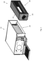
- Figure 1 shows a fresh air plenum module 10 and a fan coil unit 12
- Figures 2 and 3 show a system comprising the fresh air plenum module 10 coupled to the fan coil unit 12. This connection can be done as a modification to a system with a pre-existing fan coil unit 12 to provide an added air injection capability, or it can be done along with installation of the fan coil unit 12.
- the fresh air plenum module 10 is for introducing a flow of fresh air from an outdoor setting to induce a flow of (conditioned) air through the fan coil unit which improves the efficiency of the operation of the fan coil unit (when the fan is operated) and also provides a new mode of operation of the fan coil unit (wherein the fan is not operated), the new mode allowing the system to provide a small amount of air conditioning at a greatly reduced energy consumption.
- the fresh air plenum module comprises a first inlet 14 for connection to an outlet 24 of the fan coil unit 12, a second inlet 16 for connection to an air handling unit (not shown), an outlet 18 for discharge of the outdoor air and the conditioned air, and a merging volume 20 in communication with the first inlet 14, the second inlet 16 and the outlet 18.
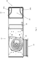
- FIGS 3 and 4 show further detail of the fan coil unit 12 and fresh air plenum module 10.
- the fan coil unit 12 comprises an inlet 22, the outlet 24, a fan 26 and a heat exchanger coil 28.
- the coil 28 is configured to receive hot or cold fluid from a central source (not shown), and the fan 26 is configured to blow/draw air from the room through the coil 28 so that heat can be exchanged between the air flow and the fluid in the coil 28.
- the fan coil unit 12 also comprises a controller (not shown) which is able to operate the fan 26 and the coil 28 separately and independently of each other.
- the fresh air plenum module 10 comprises a first plenum compartment 30a and a second plenum compartment 30b.
- the first plenum compartment 30a and the second plenum compartment 30b are connected to the second inlet 16 such that outdoor air is able to flow from the second inlet 16 into either the first plenum compartment 30a and the second plenum compartment 30b.
- the first plenum compartment 30a is located on a first internal side of the fresh air plenum module 10, the first internal side being a top side of the fresh air plenum module 10.
- the second plenum compartment 30b is located on a second internal side of the fresh air plenum module 10, the second internal side being a bottom side of the fresh air plenum module 10. Accordingly, the first internal side and the second internal side are in a facing spaced relationship.
- the first plenum compartment 30a and second plenum compartment 30b extend along the whole width of the first internal side and the second internal side respectively.
- the volume of the first plenum compartment 30a is the same as the volume of the second plenum compartment 30b.
- the volume of the first plenum compartment 30a may be greater than the volume of the second plenum compartment 30b or the volume of the second plenum compartment 30b may be greater than the volume of the first plenum compartment 30a.
- the fresh air plenum module 10 comprises an air divider 32 configured to distribute the outdoor air flow from the second inlet 16 between the first plenum compartment 30a and the second plenum compartment 30b.
- the air divider 32 is configured to distribute the outdoor air flow from the second inlet 16 equally between the first plenum compartment 30a and the second plenum compartment 30b, but the air divider 32 may be configured to distribute the outdoor air flow from the second inlet 16 unequally between the first plenum compartment 30a and the second plenum compartment 30b depending on the requirements of the environment.
- the first plenum compartment 30a is configured to supply the outdoor air to a first set 34a of one or more nozzles 34
- the second plenum compartment 30b is configured to supply the outdoor air to a second set 34b of one or more nozzles 34.
- Each nozzle 34 is configured to inject the outdoor air into the merging volume 20 of the fresh air plenum module 10. As such, each nozzle 34 may be shaped in order to provide a high-velocity injection of outdoor air into the merging volume 20. Each nozzle 34 is facing/directed towards the outlet 18.
- the first set of nozzles 34a and the second set of nozzles 34b are configured to provide air injection flow characteristics depending on the requirements of the system/environment.
- the first set of nozzles 34a comprises the same number of nozzles 34 as the second set of nozzles 34b; however, the first set of nozzles 34a may comprise more nozzles 34 than the second set of nozzles 34b, or the second set of nozzles 34b may comprise more nozzles 34 than the first set of nozzles 34a.
- the first set of nozzles 34a is distributed on a nozzle wall of the first plenum compartment 30a.
- the first set of nozzles 34a comprises four rows of nozzles 34, each row comprising a straight line of nozzles 34 facing towards the outlet 18.
- Each row of nozzles 34 is offset from the rows of nozzles adjacent to it, to form a "staggered" arrangement.
- the second set of nozzles 34b is distributed on a nozzle wall of the second plenum compartment 30b.
- the second set of nozzles 34b is arranged in the same way as the first set of nozzles 34a.
- the nozzle wall of the first plenum compartment 30a and the nozzle wall of the second plenum compartment 30b each comprise a curved portion on which the nozzles 34 are distributed.
- the curved portions are secured to the first internal side and second internal side respectively.
- FIG. 5 shows another example of a fresh air plenum 100.
- the fresh air plenum 100 is similar to the fresh air plenum 10 except in that it has differently shaped plenum compartments 30a, 30b and different nozzle 34 arrangements.
- the nozzle wall of the first plenum compartment 30a and the nozzle wall of the second plenum compartment 30b each comprise a straight portion.
- the straight portion of the nozzle wall of the first plenum compartment 30a is angled at 60 degrees from the first internal side of the fresh air plenum module 100.
- the straight portion of the nozzle wall of the second plenum compartment 30b is angled at 60 degrees from the second internal side of the fresh air plenum module 100.
- each plenum compartment 30a, 30b further comprises a curved portion that protrudes into the merging volume 20 and a second straight portion which joins the curved portion to an edge of the outlet 18.
- the volume of the plenum compartments 30a, 30b of the fresh air plenum module 100 is greater than the volume of the plenum compartments 30a, 30b of the fresh air plenum module 10.
- the first set of nozzles 34a is distributed on the nozzle wall of the first plenum compartment 30a.
- the first set of nozzles 34a comprises four nozzles 34 spaced apart from each other, each facing towards the outlet 18.
- Each nozzle 34 is rectangular in shape, and extends across the full width of the outlet 18.
- the second set of nozzles 34b is distributed on a nozzle wall of the second plenum compartment 30b in the same way as the first set of nozzles 34a.
- the first plenum compartment 30a is the same as the second plenum compartment 30b.
- the second set of nozzles 34b is arranged in the same way as the first set of nozzles 34a.
- the nozzle wall and arrangement of the second set of nozzles 34 of the second plenum compartment 30b may be different from first plenum compartment 30a, depending on the situation.
- the shape, number and arrangement of the nozzles of the first set of nozzles 34a and/or the nozzles of the second set of nozzles 34b may be selected to adapt the air flow to differing types of fan coil unit and/or for different shapes of interior/housing of the plenum module 10, 100.
- the fresh air plenum module 10, 100 can be fitted to the fan coil unit 12 prior to installation of the system or can be retrofitted to a pre-installed fan coil unit 12.
- the first inlet 14 is fitted to the outlet 24 of the fan coil unit 12.
- the second inlet 16 of the fresh air plenum module 10, 100 is fluidly connected (e.g. by a tube or pipe network) to the outlet of an air handling system (not shown).
- the system comprising the fresh air plenum module 10, 100 and the fan coil unit 12 can be operated in one of an induction mode, a boost mode, and an eco mode.
- fresh/outdoor air is provided to the second inlet 16 of the fresh air plenum module 10, 100, the coil 28 of the fan coil unit 12 is operated (to condition the air by heating or cooling) and the fan 26 of the fan coil unit 12 is not operated.
- the flow of fresh/outdoor air from the second inlet 16, through the merging volume 20 and out of the outlet 18 causes a drop in pressure in the merging volume 20.
- This negative (gauge) pressure in the merging volume 20 pulls air passively from the fan coil unit 12 through the first inlet 14 and into the fresh air plenum module 10, 100.
- the flow of fresh/outdoor air through the fresh air plenum module 10, 100 induces a flow of air through the fan coil unit 12 and the fresh air plenum module 10, 100, this flow of air being conditioned by the coil 28 as it passes through it.
- the induction mode of the system is therefore able to provide fresh air circulation and conditioning functionality without requiring the fan 26 to be operated, reducing the energy consumption required for this functionality in comparison to present air conditioning systems.
- fresh/outdoor air is provided to the second inlet 16 of the fresh air plenum module 10, 100, the coil 28 of the fan coil unit 12 is operated (to condition the air by heating or cooling) and the fan 26 of the fan coil unit 12 is operated to draw air through the fan coil unit 12 and fresh air plenum module 10, 100.
- fresh/outdoor air is provided to the second inlet 16 of the fresh air plenum module 10, 100, and the coil 28 and the fan 26 of the fan coil unit 12 are not operated. Again, the flow of fresh/outdoor air through the fresh air plenum module 10 in this mode still induces a flow of air through the fan coil unit 12 and the fresh air plenum module 10, 100, even when air conditioning functionality is not required.
- the induction of a flow of air through the coil 28 of the fan coil unit 12 even when air conditioning functionality is not required can prevent dust from building up on the coil 28 and/or improve the air change rate of the room/system, without requiring the fan 26 to be operated (and, for example, consuming energy unnecessarily).
Landscapes
- Engineering & Computer Science (AREA)
- Chemical & Material Sciences (AREA)
- Combustion & Propulsion (AREA)
- Mechanical Engineering (AREA)
- General Engineering & Computer Science (AREA)
- Signal Processing (AREA)
- Physics & Mathematics (AREA)
- Fuzzy Systems (AREA)
- Mathematical Physics (AREA)
- Thermal Sciences (AREA)
- Fluid Mechanics (AREA)
- Jet Pumps And Other Pumps (AREA)
Abstract
Description
- The present invention relates to a fresh air plenum module for the introduction of fresh air into an indoor setting, where the fresh air plenum module is for fitting to a fan coil unit. It also relates to a corresponding method of operating a system comprising a fan coil unit fitted with a fresh air plenum module.
- Conventionally, air handling units (AHUs) and the like are responsible for the distribution of fresh air within a commercial or industrial building such as a hotel or office.
- For example, an AHU takes fresh ambient air from outside (e.g. outdoors) and distributes it to one or more rooms inside of the building (e.g. indoors) via one or more ducts. One or more of these rooms may each comprise a fan coil unit (FCU) responsible for conditioning (e.g. heating and/or cooling) the air in its associated room.
- A typical FCU comprises a heat exchanger coil and a fan. The coil is configured to receive hot or cold fluid from a central plant, and the fan is configured to blow or draw air from the room through the coil so that heat can be exchanged between the air flow and the fluid in the coil.
- It would beneficial if the flow of fresh ambient air that is introduced into a room of a building could be utilised to improve the efficiency of operation of a FCU located in said room.
- According to a first aspect of the invention, there is provided a fresh air plenum module for attachment to a fan coil unit for introducing air from an outdoor setting, wherein the fresh air plenum module comprises: a first inlet for connection to an outlet of the fan coil unit; a second inlet for connection to an air handling unit; an outlet for discharge of the outdoor air and the conditioned air; and a merging volume in communication with the first inlet, the second inlet and the outlet; wherein, in use, a flow of the outdoor air from the second inlet through the merging volume to the outlet generates a pressure gradient which induces a flow of conditioned air through the first inlet and into the fresh air plenum module from the fan coil unit.
- With the above fresh air plenum module it is possible to easily modify a pre-existing fan coil unit to add a fresh (outdoor) air injection capability where the injection of fresh air induces an increase in the flow of conditioned air through the fan coil unit. Thus, upon new installation or as a retrofit for previously installed fan coil units it becomes possible to add in the proposed fresh air plenum module to thereby introduce a fresh air induction function to the system, which improves the efficiency of the operation of the fan coil unit (when the fan is operated) and also provides a new mode of operation of the fan coil unit (wherein the fan is not operated) which allows the system to provide some air conditioning at a greatly reduced energy consumption.
- The flow of outdoor air through the merging volume causes a drop in static pressure in the merging volume. This decrease in pressure, e.g. generating a negative (gauge) pressure, in the merging volume relative to the pressure in the fan coil unit causes air to be pulled passively from the fan coil unit, through the first inlet and into the fresh air plenum module. Thus, the flow of outdoor air through the merging volume induces an airflow through the fan coil unit.
- The fresh air plenum module is considered to be a new air plenum module, in that it is configured/suitable for introducing new air into a fan coil unit system and/or its environment, the new air being fresh/outdoor air.
- On the other hand, conditioned air is air from the environment (e.g. indoors, hotel room) that has passed through the coil of the fan coil unit (so that heat can be exchanged between the air flow and the fluid in the coil).
- In some implementations the fresh air plenum module is advantageously configured to induce a flow of conditioned air through the fan coil unit at an air flow rate of between 20% and 300% of the air flow rate through the second inlet (e.g. the maximum air flow rate that can be generated by an AHU).
- The fresh air plenum module may comprise at least one nozzle fluidly connected to the second inlet for injecting the outdoor air into the merging volume.
- The fresh air plenum module may comprise a first plenum compartment connected to the second inlet and configured to supply outdoor air to at least one first nozzle; and a second plenum compartment connected to the second inlet and configured to supply outdoor air to at least one second nozzle.
- The first plenum compartment may be located on a first internal side of the fresh air plenum module; and the second plenum compartment may be located on a second internal side of the fresh air plenum module; wherein the first internal side and the second internal side are in a facing spaced relationship.
- The second inlet may be configured to divide the outdoor air flow from the air handling unit equally between the first plenum compartment and the second plenum compartment.
- The second inlet may be configured to direct more than half of the outdoor airflow from the air handling unit to the first plenum compartment.
- The second inlet may be configured to direct more than half of the outdoor airflow from the air handling unit to the second plenum compartment.
- A volume of the first plenum compartment may be the same as a volume of the second plenum compartment.
- A volume of the first plenum compartment may be greater than a volume of the second plenum compartment.
- A volume of the second plenum compartment may be greater than a volume of the first plenum compartment.
- A width of the or each first nozzle may be the same as a width of the outlet.
- A width of the or each second nozzle may be the same as a width of the outlet.
- The shape of the or each first nozzle may be rectangular or semi-circular.
- The shape of the or each second nozzle may be rectangular or semi-circular.
- The shape of the or each first nozzle and/or the shape of the or each second nozzle may be configured to induce a flow of air at a predetermined air flow rate.
- The shape of the or each first nozzle may be the same as the shape of the or each second nozzle.
- The shape of the or each first nozzle may be different from the shape of the or each second nozzle.
- The at least one first nozzle may be a first set of nozzles; and the at least one second nozzle may be a second set of nozzles.
- The first set of nozzles may comprise more nozzles than the second set of nozzles.
- The second set of nozzles may comprise more nozzles than the first set of nozzles.
- The first set of nozzles may comprise a plurality of nozzles distributed in a straight line facing the outlet.
- The first set of nozzles may comprise a plurality of nozzles distributed in a plurality of straight lines facing the outlet.
- Where the first set of nozzles is distributed in a plurality of straight lines, the nozzles in one line may be offset from the nozzles in adjacent line(s).
- The second set of nozzles may comprise a plurality of nozzles distributed in a straight line facing the outlet.
- The second set of nozzles may comprise a plurality of nozzles distributed in a plurality of straight lines facing the outlet.
- Where the second set of nozzles is distributed in a plurality of straight lines, the nozzles in one line may be offset from the nozzles in adjacent line(s).
- The arrangement of the first set of nozzles and/or the arrangement of the second set of nozzles may be configured to suit the target FCU.
- The arrangement of the first set of nozzles and/or the arrangement of the second set of nozzles may be configured to induce a flow of air at a predetermined air flow rate.
- The arrangement of the first set of nozzles and/or the arrangement of the second set of nozzles may be configured to maintain a predetermined pressure in the first plenum compartment and/or the second plenum compartment, respectively.
- The nozzle wall of the first plenum compartment may comprise a curved portion.
- The nozzle wall of the first plenum compartment may comprise a straight portion, and an angle between the straight portion and the first internal side of the fresh air plenum module is less than 60 degrees, preferably less than 30 degrees.
- The nozzle wall of the second plenum compartment may comprise a curved portion.
- The nozzle wall of the second plenum compartment may comprise a straight portion, and an angle between the straight portion and the second internal side of the fresh air plenum module is less than 60 degrees, preferably less than 30 degrees.
- According to a second aspect of the invention, there is provided a system comprising the fresh air plenum module according to the first aspect and a fan coil unit, wherein the first inlet of the fresh air plenum module is coupled to the outlet of the fan coil unit.
- The system may comprise an air handling unit, wherein the second inlet of the fresh air plenum module is connected to the outlet of the air handling unit.
- The fan coil unit may have a controller configured to independently operate the coil of the fan coil unit and the fan of the fan coil unit.
- The controller may be configured to operate the system in an induction mode.
- The induction mode may be defined in that: the coil of the fan coil unit is operated and the fan of the fan coil unit is not operated, and wherein the flow of conditioned air through the fan coil unit is induced by the pressure gradient generated by the flow of outdoor air through the fresh air plenum module.
- The controller may be configured to operate the system in a boost mode.
- The boost mode may be defined in that: the coil of the fan coil unit is operated and the fan of the fan coil unit is operated, and wherein the flow of conditioned air through the fan coil unit is provided by the pressure gradient generated by the flow of outdoor air through the fresh air plenum module and the operation of the fan.
- The controller may be configured to operate the system in an eco mode.
- The eco mode may be defined in that: the coil of the fan coil unit is not operated and the fan of the fan coil unit is not operated, and wherein the flow of outdoor air through the fresh air plenum module generates a pressure gradient which induces a flow of air through the fan coil unit.
- It is thus apparent that the 'eco mode' is a mode of operation wherein the fan coil unit is turned off and/or consuming no (or at least low) power. Accordingly, 'eco mode' as used herein can also be taken to mean economy mode', or 'green mode'.
- According to a third aspect, there is provided a method of installation of a fresh air plenum module or system according to the first or second aspect, the method comprising: providing the fresh air plenum module; fitting the first inlet of the fresh air plenum module to the outlet of a fan coil unit; and connecting the second inlet of the fresh air plenum module to the outlet of an air handling system.
- According to a fourth aspect, there is provided a method of operating a system according to the second aspect, the method comprising operating the system in an induction mode, the induction mode comprising: providing outdoor air to the second inlet of the fresh air plenum module; operating a coil of the fan coil unit; and not operating a fan of the fan coil unit; wherein the flow of conditioned air through the fan coil unit is induced by the pressure gradient generated by the flow of outdoor air through the fresh air plenum module.
- The method may comprise operating the system in a boost mode, the boost mode comprising: providing outdoor air to the second inlet of the fresh air plenum module; operating the coil of the fan coil unit; and operating the fan of the fan coil unit; wherein the flow of conditioned air through the fan coil unit is provided by the pressure gradient generated by the flow of outdoor air through the fresh air plenum module and the operation of the fan.
- The method may comprise operating the system in an eco mode, the eco mode comprising: providing outdoor air to the second inlet of the fresh air plenum module; not operating a coil of the fan coil unit; and not operating a fan of the fan coil unit; wherein the pressure gradient generated by the flow of outdoor air through the fresh air plenum module induces a flow of air through the fan coil unit.
- The present invention will now be described, by way of example only, with reference to the accompanying drawings, in which:
-
Figure 1 shows a fresh air plenum module and a fan coil unit; -
Figure 2 shows the fresh air plenum module ofFigure 1 connected to the fan coil unit ofFigure 1 ; -
Figure 3 shows a cross-sectional side view of the system ofFigure 2 ; -
Figure 4 shows a cross-sectional front view of the fresh air plenum module ofFigures 1 and2 without the fan coil unit; and -
Figure 5 shows a perspective view of another fresh air plenum module . -
Figure 1 shows a freshair plenum module 10 and afan coil unit 12, andFigures 2 and3 show a system comprising the freshair plenum module 10 coupled to thefan coil unit 12. This connection can be done as a modification to a system with a pre-existingfan coil unit 12 to provide an added air injection capability, or it can be done along with installation of thefan coil unit 12. The freshair plenum module 10 is for introducing a flow of fresh air from an outdoor setting to induce a flow of (conditioned) air through the fan coil unit which improves the efficiency of the operation of the fan coil unit (when the fan is operated) and also provides a new mode of operation of the fan coil unit (wherein the fan is not operated), the new mode allowing the system to provide a small amount of air conditioning at a greatly reduced energy consumption. - The fresh air plenum module comprises a
first inlet 14 for connection to anoutlet 24 of thefan coil unit 12, asecond inlet 16 for connection to an air handling unit (not shown), anoutlet 18 for discharge of the outdoor air and the conditioned air, and a mergingvolume 20 in communication with thefirst inlet 14, thesecond inlet 16 and theoutlet 18. -
Figures 3 and4 show further detail of thefan coil unit 12 and freshair plenum module 10. - The
fan coil unit 12 comprises aninlet 22, theoutlet 24, afan 26 and aheat exchanger coil 28. Thecoil 28 is configured to receive hot or cold fluid from a central source (not shown), and thefan 26 is configured to blow/draw air from the room through thecoil 28 so that heat can be exchanged between the air flow and the fluid in thecoil 28. Thefan coil unit 12 also comprises a controller (not shown) which is able to operate thefan 26 and thecoil 28 separately and independently of each other. - In particular, the fresh
air plenum module 10 comprises afirst plenum compartment 30a and asecond plenum compartment 30b. Thefirst plenum compartment 30a and thesecond plenum compartment 30b are connected to thesecond inlet 16 such that outdoor air is able to flow from thesecond inlet 16 into either thefirst plenum compartment 30a and thesecond plenum compartment 30b. - In this example, the
first plenum compartment 30a is located on a first internal side of the freshair plenum module 10, the first internal side being a top side of the freshair plenum module 10. Thesecond plenum compartment 30b is located on a second internal side of the freshair plenum module 10, the second internal side being a bottom side of the freshair plenum module 10. Accordingly, the first internal side and the second internal side are in a facing spaced relationship. Thefirst plenum compartment 30a andsecond plenum compartment 30b extend along the whole width of the first internal side and the second internal side respectively. - In this example, the volume of the
first plenum compartment 30a is the same as the volume of thesecond plenum compartment 30b. However, the volume of thefirst plenum compartment 30a may be greater than the volume of thesecond plenum compartment 30b or the volume of thesecond plenum compartment 30b may be greater than the volume of thefirst plenum compartment 30a. - The fresh
air plenum module 10 comprises anair divider 32 configured to distribute the outdoor air flow from thesecond inlet 16 between thefirst plenum compartment 30a and thesecond plenum compartment 30b. In this example theair divider 32 is configured to distribute the outdoor air flow from thesecond inlet 16 equally between thefirst plenum compartment 30a and thesecond plenum compartment 30b, but theair divider 32 may be configured to distribute the outdoor air flow from thesecond inlet 16 unequally between thefirst plenum compartment 30a and thesecond plenum compartment 30b depending on the requirements of the environment. - The
first plenum compartment 30a is configured to supply the outdoor air to afirst set 34a of one or more nozzles 34, and thesecond plenum compartment 30b is configured to supply the outdoor air to asecond set 34b of one or more nozzles 34. - Each nozzle 34 is configured to inject the outdoor air into the merging
volume 20 of the freshair plenum module 10. As such, each nozzle 34 may be shaped in order to provide a high-velocity injection of outdoor air into the mergingvolume 20. Each nozzle 34 is facing/directed towards theoutlet 18. - The first set of
nozzles 34a and the second set ofnozzles 34b are configured to provide air injection flow characteristics depending on the requirements of the system/environment. - In the exemplary
fresh air plenum 10 ofFigures 1-4 , the first set ofnozzles 34a comprises the same number of nozzles 34 as the second set ofnozzles 34b; however, the first set ofnozzles 34a may comprise more nozzles 34 than the second set ofnozzles 34b, or the second set ofnozzles 34b may comprise more nozzles 34 than the first set ofnozzles 34a. - The first set of
nozzles 34a is distributed on a nozzle wall of thefirst plenum compartment 30a. The first set ofnozzles 34a comprises four rows of nozzles 34, each row comprising a straight line of nozzles 34 facing towards theoutlet 18. Each row of nozzles 34 is offset from the rows of nozzles adjacent to it, to form a "staggered" arrangement. - The second set of
nozzles 34b is distributed on a nozzle wall of thesecond plenum compartment 30b. In this example, the second set ofnozzles 34b is arranged in the same way as the first set ofnozzles 34a. - In this example, as shown in
Figure 3 , the nozzle wall of thefirst plenum compartment 30a and the nozzle wall of thesecond plenum compartment 30b each comprise a curved portion on which the nozzles 34 are distributed. The curved portions are secured to the first internal side and second internal side respectively. -
Figure 5 shows another example of afresh air plenum 100. Thefresh air plenum 100 is similar to thefresh air plenum 10 except in that it has differently shapedplenum compartments - For example, the nozzle wall of the
first plenum compartment 30a and the nozzle wall of thesecond plenum compartment 30b each comprise a straight portion. The straight portion of the nozzle wall of thefirst plenum compartment 30a is angled at 60 degrees from the first internal side of the freshair plenum module 100. The straight portion of the nozzle wall of thesecond plenum compartment 30b is angled at 60 degrees from the second internal side of the freshair plenum module 100. - The nozzle wall of each
plenum compartment volume 20 and a second straight portion which joins the curved portion to an edge of theoutlet 18. Thus, it can be seen that the volume of the plenum compartments 30a, 30b of the freshair plenum module 100 is greater than the volume of the plenum compartments 30a, 30b of the freshair plenum module 10. - The first set of
nozzles 34a is distributed on the nozzle wall of thefirst plenum compartment 30a. The first set ofnozzles 34a comprises four nozzles 34 spaced apart from each other, each facing towards theoutlet 18. Each nozzle 34 is rectangular in shape, and extends across the full width of theoutlet 18. - The second set of
nozzles 34b is distributed on a nozzle wall of thesecond plenum compartment 30b in the same way as the first set ofnozzles 34a. - In both of the examples above, the
first plenum compartment 30a is the same as thesecond plenum compartment 30b. Particularly, the second set ofnozzles 34b is arranged in the same way as the first set ofnozzles 34a. However, the nozzle wall and arrangement of the second set of nozzles 34 of thesecond plenum compartment 30b may be different fromfirst plenum compartment 30a, depending on the situation. - In other words, the shape, number and arrangement of the nozzles of the first set of
nozzles 34a and/or the nozzles of the second set ofnozzles 34b may be selected to adapt the air flow to differing types of fan coil unit and/or for different shapes of interior/housing of theplenum module - The fresh
air plenum module fan coil unit 12 prior to installation of the system or can be retrofitted to a pre-installedfan coil unit 12. - In order to connect the fresh
air plenum module fan coil unit 12, thefirst inlet 14 is fitted to theoutlet 24 of thefan coil unit 12. Thesecond inlet 16 of the freshair plenum module - In use, the system comprising the fresh
air plenum module fan coil unit 12 can be operated in one of an induction mode, a boost mode, and an eco mode. - In the induction mode of operation, fresh/outdoor air is provided to the
second inlet 16 of the freshair plenum module coil 28 of thefan coil unit 12 is operated (to condition the air by heating or cooling) and thefan 26 of thefan coil unit 12 is not operated. The flow of fresh/outdoor air from thesecond inlet 16, through the mergingvolume 20 and out of theoutlet 18 causes a drop in pressure in the mergingvolume 20. This negative (gauge) pressure in the mergingvolume 20 pulls air passively from thefan coil unit 12 through thefirst inlet 14 and into the freshair plenum module air plenum module fan coil unit 12 and the freshair plenum module coil 28 as it passes through it. - The induction mode of the system is therefore able to provide fresh air circulation and conditioning functionality without requiring the
fan 26 to be operated, reducing the energy consumption required for this functionality in comparison to present air conditioning systems. - In the boost mode of operation, fresh/outdoor air is provided to the
second inlet 16 of the freshair plenum module coil 28 of thefan coil unit 12 is operated (to condition the air by heating or cooling) and thefan 26 of thefan coil unit 12 is operated to draw air through thefan coil unit 12 and freshair plenum module - In this mode, the flow of fresh/outdoor air through the fresh
air plenum module fan coil unit 12 and the freshair plenum module - In the eco mode of operation, fresh/outdoor air is provided to the
second inlet 16 of the freshair plenum module coil 28 and thefan 26 of thefan coil unit 12 are not operated. Again, the flow of fresh/outdoor air through the freshair plenum module 10 in this mode still induces a flow of air through thefan coil unit 12 and the freshair plenum module - The induction of a flow of air through the
coil 28 of thefan coil unit 12 even when air conditioning functionality is not required can prevent dust from building up on thecoil 28 and/or improve the air change rate of the room/system, without requiring thefan 26 to be operated (and, for example, consuming energy unnecessarily).
Claims (15)
- A fresh air plenum module for attachment to a fan coil unit for introducing air from an outdoor setting, wherein the fresh air plenum module comprises:a first inlet for connection to an outlet of the fan coil unit;a second inlet for connection to an air handling unit;an outlet for discharge of the outdoor air and the conditioned air; anda merging volume in communication with the first inlet, the second inlet and the outlet;wherein, in use, a flow of the outdoor air from the second inlet through the merging volume to the outlet generates a pressure gradient which induces a flow of air through the first inlet and into the fresh air plenum module from the fan coil unit.
- A fresh air plenum module as claimed in claim 1, wherein the fresh air plenum module comprises at least one nozzle fluidly connected to the second inlet for injecting the outdoor air into the merging volume.
- A fresh air plenum module as claimed in claim 2, wherein the fresh air plenum module comprises a first plenum compartment connected to the second inlet and configured to supply outdoor air to a first set of one or more nozzles; and a second plenum compartment connected to the second inlet and configured to supply outdoor air to a second set of one or more nozzles.
- A fresh air plenum module as claimed in claim 3, wherein the first plenum compartment is located on a first internal side of the fresh air plenum module; and the second plenum compartment is located on a second internal side of the fresh air plenum module; wherein the first internal side and the second internal side are in a facing spaced relationship.
- A fresh air plenum module as claimed in claim 3 or claim 4, wherein the second inlet is configured to divide the outdoor air flow from the air handling unit equally between the first plenum compartment and the second plenum compartment.
- A fresh air plenum module as claimed in claim 3 or claim 4, wherein the fresh air plenum module is configured to direct more than half of the outdoor airflow from the air handling unit to the first plenum compartment; or the fresh air plenum module is configured to direct more than half of the outdoor airflow from the air handling unit to the second plenum compartment.
- A fresh air plenum module as claimed in any of claims 3 to 6, wherein a volume of the first plenum compartment is greater than a volume of the second plenum compartment; or the volume of the second plenum compartment is greater than the volume of the first plenum compartment.
- A fresh air plenum module as claimed in any of claims 3 to 7, wherein the first set of nozzles comprises more nozzles than the second set of nozzles; or wherein the second set of nozzles comprises more nozzles than the first set of nozzles.
- A system comprising the fresh air plenum module of any preceding claim and a fan coil unit, wherein the first inlet of the fresh air plenum module is coupled to the outlet of the fan coil unit.
- A system as claimed in claim 9, comprising an air handling unit, wherein the second inlet of the fresh air plenum module is connected to the outlet of the air handling unit.
- A system as claimed in claim 9 or claim 10, wherein the fan coil unit has a controller configured to independently operate the coil of the fan coil unit and the fan of the fan coil unit.
- A method of installation of a fresh air plenum module or system as claimed in any preceding claim, the method comprising: providing the fresh air plenum module; fitting the first inlet of the fresh air plenum module to the outlet of a fan coil unit; and connecting the second inlet of the fresh air plenum module to the outlet of an air handling system.
- A method of operating a system as claimed in any of claims 9 to 11, the method comprising operating the system in an induction mode, the induction mode comprising:providing outdoor air to the second inlet of the fresh air plenum module;operating a coil of the fan coil unit; andnot operating a fan of the fan coil unit;wherein the flow of conditioned air through the fan coil unit is induced by the pressure gradient generated by the flow of outdoor air through the fresh air plenum module.
- A method as claimed in claim 13, the method comprising operating the system in a boost mode, the boost mode comprising:providing outdoor air to the second inlet of the fresh air plenum module;operating the coil of the fan coil unit; andoperating the fan of the fan coil unit;wherein the flow of conditioned air through the fan coil unit is provided by the pressure gradient generated by the flow of outdoor air through the fresh air plenum module and the operation of the fan.
- A method as claimed in claim 13 or claim 14, the method comprising operating the system in an eco mode, the eco mode comprising:providing outdoor air to the second inlet of the fresh air plenum module;not operating the coil of the fan coil unit; andnot operating the fan of the fan coil unit;wherein the pressure gradient generated by the flow of outdoor air through the fresh air plenum module induces a flow of air through the fan coil unit.
Priority Applications (3)
| Application Number | Priority Date | Filing Date | Title |
|---|---|---|---|
| EP22156617.7A EP4227587A1 (en) | 2022-02-14 | 2022-02-14 | Fresh air plenum module for a fan coil unit |
| US18/166,201 US20230258343A1 (en) | 2022-02-14 | 2023-02-08 | Fresh air plenum module for a fan coil unit |
| CN202310105629.1A CN116592421A (en) | 2022-02-14 | 2023-02-13 | Fresh air boost module for fan coil units |
Applications Claiming Priority (1)
| Application Number | Priority Date | Filing Date | Title |
|---|---|---|---|
| EP22156617.7A EP4227587A1 (en) | 2022-02-14 | 2022-02-14 | Fresh air plenum module for a fan coil unit |
Publications (1)
| Publication Number | Publication Date |
|---|---|
| EP4227587A1 true EP4227587A1 (en) | 2023-08-16 |
Family
ID=80928825
Family Applications (1)
| Application Number | Title | Priority Date | Filing Date |
|---|---|---|---|
| EP22156617.7A Withdrawn EP4227587A1 (en) | 2022-02-14 | 2022-02-14 | Fresh air plenum module for a fan coil unit |
Country Status (3)
| Country | Link |
|---|---|
| US (1) | US20230258343A1 (en) |
| EP (1) | EP4227587A1 (en) |
| CN (1) | CN116592421A (en) |
Citations (5)
| Publication number | Priority date | Publication date | Assignee | Title |
|---|---|---|---|---|
| US3263743A (en) * | 1961-10-11 | 1966-08-02 | Teves Kg Alfred | Air-conditioning apparatus |
| US4657178A (en) * | 1980-09-05 | 1987-04-14 | Camp Dresser & Mckee | Mixing box |
| US6213867B1 (en) * | 2000-01-12 | 2001-04-10 | Air Handling Engineering Ltd. | Venturi type air distribution system |
| DE202007001429U1 (en) * | 2007-01-22 | 2007-03-22 | Ltg Aktiengesellschaft | Heating, cooling and/or ventilating device for rooms in building has ventilation device connected directly and/or indirectly to wall apertures |
| DE102008007641A1 (en) * | 2008-02-04 | 2009-08-06 | Pluggit International B.V. | Ventilation device and method for air conditioning a room |
-
2022
- 2022-02-14 EP EP22156617.7A patent/EP4227587A1/en not_active Withdrawn
-
2023
- 2023-02-08 US US18/166,201 patent/US20230258343A1/en active Pending
- 2023-02-13 CN CN202310105629.1A patent/CN116592421A/en active Pending
Patent Citations (5)
| Publication number | Priority date | Publication date | Assignee | Title |
|---|---|---|---|---|
| US3263743A (en) * | 1961-10-11 | 1966-08-02 | Teves Kg Alfred | Air-conditioning apparatus |
| US4657178A (en) * | 1980-09-05 | 1987-04-14 | Camp Dresser & Mckee | Mixing box |
| US6213867B1 (en) * | 2000-01-12 | 2001-04-10 | Air Handling Engineering Ltd. | Venturi type air distribution system |
| DE202007001429U1 (en) * | 2007-01-22 | 2007-03-22 | Ltg Aktiengesellschaft | Heating, cooling and/or ventilating device for rooms in building has ventilation device connected directly and/or indirectly to wall apertures |
| DE102008007641A1 (en) * | 2008-02-04 | 2009-08-06 | Pluggit International B.V. | Ventilation device and method for air conditioning a room |
Also Published As
| Publication number | Publication date |
|---|---|
| US20230258343A1 (en) | 2023-08-17 |
| CN116592421A (en) | 2023-08-15 |
Similar Documents
| Publication | Publication Date | Title |
|---|---|---|
| US9982899B2 (en) | Displacement-induction neutral wall air terminal unit | |
| EP0779478B1 (en) | Ceiling mounted indoor unit for an air conditioning system | |
| US6213867B1 (en) | Venturi type air distribution system | |
| KR101681870B1 (en) | Ventilation Device | |
| CN107327929B (en) | Vertical air conditioner and control method thereof | |
| US20100140363A1 (en) | Air powered terminal unit and system | |
| CN101240917B (en) | Device for cooling and warming a space in a building | |
| US12320540B2 (en) | Air conditioning system | |
| US20230258343A1 (en) | Fresh air plenum module for a fan coil unit | |
| JP7240257B2 (en) | air conditioning system | |
| JP6502696B2 (en) | Air conditioning system for living room using air supply box and air supply box | |
| RU2010100754A (en) | MODULAR VENTILATION SYSTEM | |
| CN203687201U (en) | Wall mounting type direct-blowing air handling unit | |
| US10775071B2 (en) | Energy recovery ventilator | |
| CN220152888U (en) | Medium-low temperature split type air treatment mechanism and clean factory building temperature and humidity control system | |
| US3463223A (en) | Terminal room air conditioner and system | |
| EP1907764B1 (en) | Air distribution system for an air conditioning system | |
| CN207268485U (en) | Floor air conditioner | |
| KR100851589B1 (en) | Air conditioning system | |
| CN220843779U (en) | A material storage room | |
| CN213178577U (en) | Machine in modularization computer lab air conditioning | |
| CN114556028B (en) | Improved methods and systems for configuring HVAC systems | |
| CN220689318U (en) | Air conditioner terminal and air conditioning system | |
| CN224080325U (en) | Indoor air treatment system | |
| EP2017538A2 (en) | Air conditioning system for dwelling hause |
Legal Events
| Date | Code | Title | Description |
|---|---|---|---|
| PUAI | Public reference made under article 153(3) epc to a published international application that has entered the european phase |
Free format text: ORIGINAL CODE: 0009012 |
|
| STAA | Information on the status of an ep patent application or granted ep patent |
Free format text: STATUS: THE APPLICATION HAS BEEN PUBLISHED |
|
| AK | Designated contracting states |
Kind code of ref document: A1 Designated state(s): AL AT BE BG CH CY CZ DE DK EE ES FI FR GB GR HR HU IE IS IT LI LT LU LV MC MK MT NL NO PL PT RO RS SE SI SK SM TR |
|
| STAA | Information on the status of an ep patent application or granted ep patent |
Free format text: STATUS: REQUEST FOR EXAMINATION WAS MADE |
|
| 17P | Request for examination filed |
Effective date: 20240214 |
|
| RBV | Designated contracting states (corrected) |
Designated state(s): AL AT BE BG CH CY CZ DE DK EE ES FI FR GB GR HR HU IE IS IT LI LT LU LV MC MK MT NL NO PL PT RO RS SE SI SK SM TR |
|
| GRAP | Despatch of communication of intention to grant a patent |
Free format text: ORIGINAL CODE: EPIDOSNIGR1 |
|
| STAA | Information on the status of an ep patent application or granted ep patent |
Free format text: STATUS: GRANT OF PATENT IS INTENDED |
|
| INTG | Intention to grant announced |
Effective date: 20250710 |
|
| STAA | Information on the status of an ep patent application or granted ep patent |
Free format text: STATUS: THE APPLICATION IS DEEMED TO BE WITHDRAWN |
|
| 18D | Application deemed to be withdrawn |
Effective date: 20251111 |