EP4227525A1 - A system for lifting a wind turbine rotor blade - Google Patents
A system for lifting a wind turbine rotor blade Download PDFInfo
- Publication number
- EP4227525A1 EP4227525A1 EP22156738.1A EP22156738A EP4227525A1 EP 4227525 A1 EP4227525 A1 EP 4227525A1 EP 22156738 A EP22156738 A EP 22156738A EP 4227525 A1 EP4227525 A1 EP 4227525A1
- Authority
- EP
- European Patent Office
- Prior art keywords
- wind turbine
- leading edge
- turbine rotor
- rotor blade
- top layer
- Prior art date
- Legal status (The legal status is an assumption and is not a legal conclusion. Google has not performed a legal analysis and makes no representation as to the accuracy of the status listed.)
- Pending
Links
- 230000001012 protector Effects 0.000 claims abstract description 86
- 239000011162 core material Substances 0.000 claims abstract description 36
- 238000010276 construction Methods 0.000 claims abstract description 13
- 239000000835 fiber Substances 0.000 claims description 7
- 230000007246 mechanism Effects 0.000 claims description 6
- 239000011208 reinforced composite material Substances 0.000 claims description 6
- 240000007182 Ochroma pyramidale Species 0.000 claims description 3
- 230000003014 reinforcing effect Effects 0.000 claims description 3
- 239000013013 elastic material Substances 0.000 claims description 2
- 239000000463 material Substances 0.000 description 8
- 238000005452 bending Methods 0.000 description 3
- 230000007423 decrease Effects 0.000 description 3
- 230000007935 neutral effect Effects 0.000 description 3
- 230000003247 decreasing effect Effects 0.000 description 2
- 230000005484 gravity Effects 0.000 description 2
- 238000004519 manufacturing process Methods 0.000 description 2
- 239000002184 metal Substances 0.000 description 2
- 229920002430 Fibre-reinforced plastic Polymers 0.000 description 1
- 239000004698 Polyethylene Substances 0.000 description 1
- 239000000853 adhesive Substances 0.000 description 1
- 230000001070 adhesive effect Effects 0.000 description 1
- 230000008859 change Effects 0.000 description 1
- 210000000080 chela (arthropods) Anatomy 0.000 description 1
- 230000000295 complement effect Effects 0.000 description 1
- 230000006835 compression Effects 0.000 description 1
- 238000007906 compression Methods 0.000 description 1
- 230000001419 dependent effect Effects 0.000 description 1
- 230000000694 effects Effects 0.000 description 1
- 239000011151 fibre-reinforced plastic Substances 0.000 description 1
- 239000011152 fibreglass Substances 0.000 description 1
- 238000009434 installation Methods 0.000 description 1
- 238000011835 investigation Methods 0.000 description 1
- 238000002955 isolation Methods 0.000 description 1
- 238000010030 laminating Methods 0.000 description 1
- 239000003562 lightweight material Substances 0.000 description 1
- 238000000034 method Methods 0.000 description 1
- 239000004033 plastic Substances 0.000 description 1
- 229920003023 plastic Polymers 0.000 description 1
- -1 polyethylene Polymers 0.000 description 1
- 229920000573 polyethylene Polymers 0.000 description 1
- 230000008569 process Effects 0.000 description 1
- 230000009467 reduction Effects 0.000 description 1
- 239000007787 solid Substances 0.000 description 1
- 230000007704 transition Effects 0.000 description 1
- 239000002023 wood Substances 0.000 description 1
Images



Classifications
-
- B—PERFORMING OPERATIONS; TRANSPORTING
- B66—HOISTING; LIFTING; HAULING
- B66C—CRANES; LOAD-ENGAGING ELEMENTS OR DEVICES FOR CRANES, CAPSTANS, WINCHES, OR TACKLES
- B66C1/00—Load-engaging elements or devices attached to lifting or lowering gear of cranes or adapted for connection therewith for transmitting lifting forces to articles or groups of articles
- B66C1/10—Load-engaging elements or devices attached to lifting or lowering gear of cranes or adapted for connection therewith for transmitting lifting forces to articles or groups of articles by mechanical means
- B66C1/108—Load-engaging elements or devices attached to lifting or lowering gear of cranes or adapted for connection therewith for transmitting lifting forces to articles or groups of articles by mechanical means for lifting parts of wind turbines
-
- F—MECHANICAL ENGINEERING; LIGHTING; HEATING; WEAPONS; BLASTING
- F03—MACHINES OR ENGINES FOR LIQUIDS; WIND, SPRING, OR WEIGHT MOTORS; PRODUCING MECHANICAL POWER OR A REACTIVE PROPULSIVE THRUST, NOT OTHERWISE PROVIDED FOR
- F03D—WIND MOTORS
- F03D13/00—Assembly, mounting or commissioning of wind motors; Arrangements specially adapted for transporting wind motor components
- F03D13/10—Assembly of wind motors; Arrangements for erecting wind motors
- F03D13/104—Rotor installation, e.g. installation of blades
-
- B—PERFORMING OPERATIONS; TRANSPORTING
- B66—HOISTING; LIFTING; HAULING
- B66C—CRANES; LOAD-ENGAGING ELEMENTS OR DEVICES FOR CRANES, CAPSTANS, WINCHES, OR TACKLES
- B66C1/00—Load-engaging elements or devices attached to lifting or lowering gear of cranes or adapted for connection therewith for transmitting lifting forces to articles or groups of articles
- B66C1/10—Load-engaging elements or devices attached to lifting or lowering gear of cranes or adapted for connection therewith for transmitting lifting forces to articles or groups of articles by mechanical means
- B66C1/12—Slings comprising chains, wires, ropes, or bands; Nets
- B66C1/122—Sling or load protectors
-
- B—PERFORMING OPERATIONS; TRANSPORTING
- B66—HOISTING; LIFTING; HAULING
- B66C—CRANES; LOAD-ENGAGING ELEMENTS OR DEVICES FOR CRANES, CAPSTANS, WINCHES, OR TACKLES
- B66C1/00—Load-engaging elements or devices attached to lifting or lowering gear of cranes or adapted for connection therewith for transmitting lifting forces to articles or groups of articles
- B66C1/10—Load-engaging elements or devices attached to lifting or lowering gear of cranes or adapted for connection therewith for transmitting lifting forces to articles or groups of articles by mechanical means
- B66C1/12—Slings comprising chains, wires, ropes, or bands; Nets
- B66C1/18—Band-type slings
-
- F—MECHANICAL ENGINEERING; LIGHTING; HEATING; WEAPONS; BLASTING
- F03—MACHINES OR ENGINES FOR LIQUIDS; WIND, SPRING, OR WEIGHT MOTORS; PRODUCING MECHANICAL POWER OR A REACTIVE PROPULSIVE THRUST, NOT OTHERWISE PROVIDED FOR
- F03D—WIND MOTORS
- F03D13/00—Assembly, mounting or commissioning of wind motors; Arrangements specially adapted for transporting wind motor components
- F03D13/10—Assembly of wind motors; Arrangements for erecting wind motors
-
- F—MECHANICAL ENGINEERING; LIGHTING; HEATING; WEAPONS; BLASTING
- F03—MACHINES OR ENGINES FOR LIQUIDS; WIND, SPRING, OR WEIGHT MOTORS; PRODUCING MECHANICAL POWER OR A REACTIVE PROPULSIVE THRUST, NOT OTHERWISE PROVIDED FOR
- F03D—WIND MOTORS
- F03D13/00—Assembly, mounting or commissioning of wind motors; Arrangements specially adapted for transporting wind motor components
- F03D13/10—Assembly of wind motors; Arrangements for erecting wind motors
- F03D13/139—Assembling or erecting wind motors by using lifting means
-
- F—MECHANICAL ENGINEERING; LIGHTING; HEATING; WEAPONS; BLASTING
- F05—INDEXING SCHEMES RELATING TO ENGINES OR PUMPS IN VARIOUS SUBCLASSES OF CLASSES F01-F04
- F05B—INDEXING SCHEME RELATING TO WIND, SPRING, WEIGHT, INERTIA OR LIKE MOTORS, TO MACHINES OR ENGINES FOR LIQUIDS COVERED BY SUBCLASSES F03B, F03D AND F03G
- F05B2230/00—Manufacture
- F05B2230/60—Assembly methods
- F05B2230/61—Assembly methods using auxiliary equipment for lifting or holding
-
- Y—GENERAL TAGGING OF NEW TECHNOLOGICAL DEVELOPMENTS; GENERAL TAGGING OF CROSS-SECTIONAL TECHNOLOGIES SPANNING OVER SEVERAL SECTIONS OF THE IPC; TECHNICAL SUBJECTS COVERED BY FORMER USPC CROSS-REFERENCE ART COLLECTIONS [XRACs] AND DIGESTS
- Y02—TECHNOLOGIES OR APPLICATIONS FOR MITIGATION OR ADAPTATION AGAINST CLIMATE CHANGE
- Y02E—REDUCTION OF GREENHOUSE GAS [GHG] EMISSIONS, RELATED TO ENERGY GENERATION, TRANSMISSION OR DISTRIBUTION
- Y02E10/00—Energy generation through renewable energy sources
- Y02E10/70—Wind energy
- Y02E10/72—Wind turbines with rotation axis in wind direction
Definitions
- the invention relates to a system for lifting a wind turbine rotor blade.
- Wind turbine rotor blades are large, heavy and fragile parts. Handling wind turbine rotor blades at the manufacturing site, during transportation or at an erection site therefore is difficult and requires specific tools and expertise. In particular when lifting a wind turbine rotor blade to a wind turbine rotor blade hub, great care must be taken to maintain the wind turbine rotor blade in a desired position without causing damage.
- blade yokes are large frames with hydraulic pincers designed for gripping a wind turbine rotor blade at opposite sections of the pressure side and the suction side.
- the blade yokes are fastened to a crane hook and further include means to control an angle of the frame and a gripped wind turbine rotor blade with reference to the horizontal direction.
- these blade yokes are heavy and costly.
- An alternative is provided by supporting the wind turbine rotor blade by simple slings guided around the wind turbine rotor blade's cross-section at a given distance around the blade centre of gravity, usually at the root section and at a midsection. Since state-of-the-art rotor blades are transported and later installed with leading and trailing edge oriented sideways, compression will be applied on these edges during installation by the slings. However, for normal operation rotor blades are designed to withstand loads in flapwise direction, but not in edgewise direction as is the case here. Hence, the slings will most likely damage the wind turbine rotor blade in particular in the midsection where the wind turbine rotor blade has an aerodynamic profile. It is therefore known to place specific protectors at the leading edge and/or at the trailing edge of the wind turbine rotor blade.
- the document DE 10 2011 113 482 B4 discloses a system for transporting a wind turbine rotor blade with a protector including a trailing edge protector and a leading edge protector fastened to a wind turbine rotor blade by means of two belts connecting both protectors on a pressure side and on a suction side of the blade.
- the leading edge protector comprises a series of longitudinal contact elements arranged parallel to each other on a tensioning rope and abutting the leading edge.
- the document US 9,016,989 B2 discloses a transportation assembly for a wind turbine rotor blade designed to transport the wind turbine rotor blade with its leading edge pointing downwards.
- the transportation assembly comprises a leading edge protector placed between a sling supporting the wind turbine rotor blade and the wind turbine rotor blade's leading edge.
- the leading edge protector is formed from a fibreglass laminate.
- the system for lifting a wind turbine rotor blade comprises
- the leading edge protector is designed to protect the leading edge of a wind turbine rotor blade when lifting the same, in particular to the hub of a rotor with horizontal axis mounted at a nacelle arranged at the top of a wind turbine tower.
- the wind turbine rotor blade may have a blade root which may have a circular cross-section, a blade tip, a longitudinal axis, a suction side surface and a pressure side surface.
- the air flows past the wind turbine rotor blade in a direction generally from the leading edge towards the trailing edge.
- the trailing edge is defined as a line connecting the rearmost points of the aerodynamic profiles, and the leading edge is defined as a line connecting those points of the aerodynamic profiles being farthest away from the rearmost points.
- a straight line connecting the leading edge and the trailing edge in an aerodynamic profile is the chord of the aerodynamic profile.
- the pressure side surface and the suction side surface each extend along the wind turbine rotor blades outer surface from the leading edge to the trailing edge.
- the wind turbine rotor blade may comprise a load carrying structure, such as a spar, for example including two spar caps and one or more shear webs placed there between, and aerodynamic outer surfaces formed by skin or shell portions supported by the load carrying structure.
- the load carrying structure or parts thereof may also be formed integral with the shells.
- the wind turbine rotor blade may comprise a suction side half shell and a pressure side half shell adhered to each other along the leading edge and along the trailing edge. These half shells may each include at least one spar cap, and one or more shear webs may be placed between the half shells and adhered thereto.
- chord When lifting the wind turbine rotor blade, it is preferred to arrange the chord more or less horizontally in order to keep wind forces low, in contrast to a vertical alignment of the chord that would cause much stronger wind forces.
- either the suction side surface or the pressure side surface of the wind turbine rotor blade points roughly downwards.
- the feature that the chord is arranged horizontally means that the chord is aligned substantially horizontally. It does not mean the chord is aligned perfectly horizontally, but may include substantial deviations, such as for example up to +/-30°.
- the leading edge protector has a front portion which is placed at the leading edge, and a lower leg which is placed below the wind turbine rotor blade, in particular at an outer surface of the wind turbine rotor blade pointing downwards, either the suction side surface or the pressure side surface.
- the leading edge protector therefore covers the outer surface of the wind turbine rotor blade in a region around the leading edge. This region in a direction towards the trailing edge extends partly over the suction side surface and/or partly over the pressure side surface, in particular by means of the lower leg arranged below the wind turbine rotor blade.
- the leading edge protector In order to reduce the deformation of the wind turbine rotor blade at the leading edge, the leading edge protector is placed between the sling and the wind turbine rotor blade.
- the leading edge protector due to the specific sandwich construction of the front portion and the lower leg, forms a unitary, stiff body.
- the leading edge protector is provided with a core material having a varying thickness. It is the thickness of the core material that imparts stiffness to the sandwich construction, and by making the core material particularly thick at the front portion and decreasing the thickness towards a free end of the lower leg, an efficient and optimal load distribution is obtained.
- the core material thickness may be selected such that it approximately levels a core material thickness within the rotor blade in a region between the leading edge and a maximum thickness chord position and, thus efficiently distributes the forces exerted by the sling over the complete length of the protector and in such way over a larger surface area of the wind turbine rotor blade covered by the leading edge protector. Since the rotor blade is designed to withstand large bending moments in flap wise direction and lower bending moments in edgewise direction, maximum core material thickness within a profile is usually located at the maximum thickness chord position and lowest to non-existent at the leading edge. Inverting this design rule for the leading edge protector helps to avoid excessive loads on the wind turbine rotor blade's outer surface, in particular at or close to the leading edge, where the wind turbine rotor blade is particularly prone to failure.
- the sandwich construction is particularly lightweight, so that the leading edge protector is easy to handle and transport. This also contributes to a safe lifting process of the wind turbine rotor blade.
- the leading edge protector is shaped such that the inner top layer extends over a defined area of an outer surface of the wind turbine rotor blade and is in contact with the entire defined area.
- the leading edge protector is provided with a complimentary shape such that it provides optimal support for the wind turbine rotor blade over the entire area covered by the leading edge protector. This contributes to the desired reduction of any deformation of the wind turbine's cross section.
- the complementary shape of the inner top layer means the leading edge protector provides optimum protection and support for the wind turbine rotor blade, wherein no gap or almost no gap is present between the inner surface of the inner top layer and the suction side surface and the pressure side surface of the rotor blade.
- the leading edge protector comprises an upper leg which extends from the front portion as an integral part of the sandwich construction and is placed above the wind turbine rotor blade. This means the leading edge protector can be used to protect a wind turbine rotor blade's leading edge, no matter whether it is supported by the sling with its pressure side or its suction side pointing downwards.
- the upper leg is placed at the wind turbine rotor blade's outer surface which is pointing upwards.
- the inner top layer and the outer top layer may extend without interruption over both legs and the front portion.
- the core material may be provided as a continuous layer also extending over both legs and the front portion.
- the leading edge protector encompasses a larger region of the wind turbine rotor blade's outer surface, including a section of the suction side and a section of the pressure side. This also helps reducing deformation of the wind turbine rotor blade's cross section.
- the thickness of the core material increases from a free end of the upper leg towards the front portion.
- the core material thickness will have a maximum value at the front portion and will decrease towards the free ends of both legs. This gives the leading edge protector the necessary shape and strength in the front portion and helps to save weight and material in both leg portions. It also helps to obtain a smooth load distribution at the free end of the upper leg.
- the wind turbine rotor blade at the longitudinal position has a shell structure with a shell thickness, wherein the thickness of the core material of the leading edge protector is selected such that the thickness of the core material at the front portion in combination with the adjacent shell thickness is not less than a maximum thickness of the shell structure in a region covered by the leading edge protector.
- the shell structure may have a sandwich construction as well and may comprise inner and outer layers of a fibre reinforced composite material and a core material placed therebetween.
- a main laminate or another comparable reinforcing structure may form an integral part of the shell structure as well. All elements of the shell structure together form the shell thickness, which may vary at the longitudinal position between the leading edge and the trailing edge.
- the shell thickness will have a maximum value at or close to the chord position where the aerodynamic profile has a maximum thickness. From there towards the leading edge, the shell thickness typically decreases and reaches a minimum value at or close to the leading edge.
- the selection of the core material thickness defined in this aspect ensures that the shell structure in combination with the leading edge protector provides sufficient stiffness at the leading edge to avoid or reduce a deformation of the wind turbine rotor blade's cross section.
- the change in thickness of the core material from the front portion towards the free end of the lower leg and/or towards the free end of the upper leg may invert a shell thickness distribution of the shell structure in a section covered by the leading edge protector.
- the core material may have a minimum thickness which may be for example half of its thickness at the front portion.
- the core material thickness at the free ends is reduced to zero or to almost zero, so that a smooth transition in stiffness towards both free ends is obtained.
- the lower leg is at least twice as long as the upper leg.
- the length of the upper leg may also be even shorter, so that it covers just a small area of the wind turbine rotor blade's upper surface near the leading edge. It was found that a short upper leg does not only save weight and material, but also supports the positioning of the leading edge protector at the wind turbine rotor blade surface.
- the lower leg and the upper leg have approximately the same length.
- both the lower leg and the upper leg may have inner surfaces shaped to correspond to the respective outer surfaces of the wind turbine rotor blade.
- both legs have approximately the same length, it is possible to use the leading edge protector in both orientations, with either the lower leg or the upper leg placed below the wind turbine rotor blade. Therefore, the wind turbine rotor blade can be supported by the leading edge protector no matter if the pressure side or the suction side points downwards.
- the leading edge protector comprises two parallel lateral boundaries formed on the outer top layer along the lower leg, and the sling is arranged between the lateral boundaries.
- the boundaries may be formed along lateral sides of the lower leg, for example by laminating one or more additional layers of a fibre material onto the outer top layer, or by attaching boundaries of any other material, such as metal or wood, to the outer top layer.
- the lateral boundaries run in parallel and have a distance to each other which is sufficiently wide for placing the sling therein between. The lateral boundaries help to prevent the sling from slipping off from the leading edge protector.
- the leading edge protector comprises a plurality of lugs extending from lateral sides of the leading edge protector.
- the lugs may for example be formed by the inner top layer and/or by the outer top layer, or by additional members attached thereto.
- the lugs are accessible for fastening a belt or rope thereto, wherein the belt or rope may be used in particular to fasten the leading edge protector to the sling. This is a simple and efficient means to prevent the leading edge protector from falling down when the sling is removed from a wind turbine rotor blade.
- the inner top layer comprises a cover layer of a soft, elastic material.
- a layer of rubber may be used.
- the softness and elasticity of the material helps to protect the wind turbine rotor blades' outer surface, in particular in view of manufacturing tolerances and variations of the actual position where the leading edge protector is applied to a given wind turbine rotor blade geometry.
- a rubber layer helps to level blade surface tolerances and also provides friction.
- the inner top layer and/or the outer top layer comprises a fibre reinforced composite material.
- the top layers can also be formed by other materials providing sufficient stability, such as sheet metal.
- a fibre reinforced composite material provides excellent stiffness at reduced weight and also provides a surface compatible with the surface of a wind turbine rotor blade. Therefore, a lightweight, strong and durable construction is obtained.
- the fibre reinforced composite material includes reinforcing fibres arranged at angles of 0°, 90°, +45° and -45° with reference to a longitudinal direction of the lower leg. This helps to obtain a particularly stiff structure with high torsional stability.
- the core material comprises balsa wood.
- any suitable core material may be used, for example a foamed plastics material such as polyethylene.
- Balsa wood is a lightweight material with excellent stiffness properties resulting in a robust and stiff design.
- the lower leg extends up to a chord position of the wind turbine rotor blade where the aerodynamic profile has a maximum thickness.
- the wind turbine rotor blade exhibits a particularly stiff structure, such as a main laminate of a half shell and/or a main spar cap. Extending the lower leg up to this chord position therefore helps to transfer loads into the load carrying structure of the wind turbine rotor blade and thus to avoid excessive forces and/or deformation at the leading edge.
- the lifting device comprises a longitudinal beam, at least one cross-beam attached to the longitudinal beam and a release mechanism, wherein the sling is connected to the cross-beam and the release mechanism is adapted to open the sling and/or to disconnect one end of the sling from the cross-beam.
- the release mechanism makes it easy to release a wind turbine rotor blade supported by the lifting device. In particular, this can be performed easily by means of the release mechanism once the wind turbine rotor blade has been attached to a hub.
- the leading edge protector may be fastened to the sling and/or to the cross-beam or any other member of the lifting device to prevent the leading edge protector from falling down.
- Figure 1 shows a wind turbine rotor blade 10 fastened to a lifting device 12.
- the wind turbine rotor blade 10 has a circular blade root 14, a blade tip 16, a leading edge 18 (not visible in figure 1 ), a trailing edge 20, a suction side 22 pointing downwards and a pressure side 24 pointing upwards.
- the wind turbine rotor blade 10 has a length of about 80 m or more. Its longitudinal axis and a profile chord 64 (see Fig. 3 ) are arranged horizontally.
- the lifting device 12 comprises a longitudinal beam 26 arranged parallel to the longitudinal axis of the wind turbine rotor blade 10 and extending over about one quarter of the wind turbine rotor blades' length. At each of the two ends of the longitudinal beam 26, the lifting device includes a shorter cross-beam 28.
- the lifting device 12 further comprises two slings 30. Each sling 30 is guided around the wind turbine rotor blades' cross-section so that a central section of each sling 30 is placed below the wind turbine rotor blade 10, at the suction side 22 thereof. Further, each sling 30 has two free ends attached to one end of the corresponding cross-beam 28.
- a midsection of the longitudinal beam 26 is provided with a chain 32 or comparable attachment means for connecting to a hook of a crane.
- the wind turbine rotor blade 10 is positioned in the lifting device 12 such that the wind turbine rotor blades' centre of gravity lies below a midpoint of the longitudinal beam 26.
- the sling 30 closer to the blade root 14 supports a cross-section already having an aerodynamic profile but with a large relative thickness.
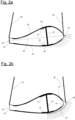
- the wind turbine rotor blade 10 has an aerodynamic profile shown in cross-section in Fig. 2a and 2b .
- Fig. 2a the wind turbine rotor blade 10 is shown supported by a sling 30 without a leading edge protector.
- the wind turbine rotor blade's cross-section is formed by two half shells adhered to each other at the leading edge 18 and at the trailing edge 20.
- the profile chord 64 is a straight line connecting the leading edge 18 and the trailing edge 20.
- the cross-section comprises a flat element 54 forming a so-called flatback profile.
- the varying thickness of the half shells shows that the half shells are formed as sandwich constructions themselves, comprising a core material extending over a majority of the half shells' widths. Only at the leading edge 18 and close to the trailing edge 20, the half shells consist of a solid, relatively thin laminate of a fibre reinforced plastics material. A shell thickness 66 is indicated for both half shells at a chord position where the shell thickness 66 has a maximum value.
- both half shells are supported by a spar cap 32 formed integral with the respective half shell. Between these spar caps 32, a shear web 34 is placed and adhered to both spar caps 32, thereby forming a central load carrying structure.
- the arrows shown at the leading edge 18 and below a front portion of the suction side 22 illustrate the forces exerted by the sling 30 onto the wind turbine rotor blade's outer surface.
- Fig. 2b the same wind turbine rotor blade 10 is shown supported by sling 30 but with a leading edge protector 36 placed between the wind turbine rotor blade 10 and the sling 30.
- the leading edge protector 36 has a front portion 38 and a lower leg 40.
- a thickness of the leading edge protector 36 is largest at the front portion 38 placed at the leading edge 18, and decreases from there continuously along the lower leg 40, towards the leading edge protector's lowermost and leftmost end which is positioned right below the spar cap 32 of the suction side 22.
- the arrows again illustrate the forces exerted onto the wind turbine rotor blades' outer surface (although for illustrative purposes, the arrow's tips end at the sling 30, not on the wind turbine rotor blades' outer surface). The forces are distributed in a much more even manner by means of the leading edge protector 36.
- Figures 3a, 3b and 3c each show a cross section of the wind turbine rotor blade 10, drawn at the same longitudinal position in different load scenarios.
- the elements of the wind turbine rotor blade 10 are depicted with the same reference numerals as in Fig. 2 .
- the wind turbine rotor blade 10 has two shear webs 34 and is positioned with the suction side 22 pointing upwards.
- the profile chord 64 is arranged horizontally.
- the cross section is drawn in a rectangular box 68 having the same size in each of the Figures 3a, 3b and 3c and deformations are exaggerated.
- Figure 3a shows the wind turbine rotor blade 10 in a neutral state without any loads.
- the aerodynamic profile is not deformed and has its regular shape.
- the shear webs 34 are arranged exactly vertically, the suction side 22 has a smooth, convex curvature.
- the leading edge 18 is positioned at a midline 70 of the rectangular box 68.
- Figure 3b shows the wind turbine rotor blade 10 when supported by a sling 30 (not shown) applied directly below the wind turbine rotor blade 10, without a leading edge protector 36.
- the cross section is deformed significantly:
- the smooth convex curvature of the suction side 22 is no longer there in particular in a rear part close to the shear web 34 arranged near the trailing edge 20, where the suction side 22 even has a concave curvature.
- Both shear webs 34 are inclined with reference to the vertical direction.
- the inclination of the flat element 54 formed at the trailing edge 20 has changed its direction as compared to Fig. 3a .
- the leading edge 18 was pressed upward- and inwardly, so that it is no longer at the height of the midline 70, but significantly above.
- a radius of curvature of the aerodynamic profile at the leading edge 18 is much smaller in Fig. 3b than in Fig. 3a . This deformation at the leading edge 18 is likely to damage the wind turbine rotor blade
- Fig. 3c the wind turbine rotor blade 10 is supported by a sling 30 with a leading edge protector 36 placed between the wind turbine rotor blade 10 and the sling 30.
- the leading edge protector 36 and the sling 30 are not shown in Fig. 3c , but are placed as is illustrated in Fig. 2b .
- the deformation at the leading edge 18 is much less than in Fig. 3b .
- the radius of curvature of the aerodynamic profile at the leading edge 18 is similar to the neutral state shown in Fig. 3c , so that the wind turbine rotor blade 10 will not be damaged.
- Figure 4 shows the leading edge protector 36 of Fig. 2b in isolation. It has a front portion 38 and a lower leg 40. These elements are formed as a sandwich construction comprising an inner top layer 44, a core material 46 and an outer top layer 48.
- the core material 46 has a thickness measured between the inner top layer 44 and the outer top layer 48, the thickness having a maximum value at the front portion 38 and decreasing continuously from there to zero at a free end 50 of the upper leg 42 and at a free end 52 of the lower leg 40.
- the inner top layer 44, the outer top layer 48 and the core material 46 each extend over the entire way from the free end 50, along the upper leg 42, over the front portion 38 and along the lower leg 40 towards the free end 52.
- a soft, elastic rubber layer 56 is provided at the outer side of the inner top layer 44. It covers the entire surface of the inner top layer 44.
- a width 58 of the leading edge protector 36 is measured along the direction of the leading edge 18 and is approximately constant over the entire leading edge protector 36.
- Figure 5 shows another leading edge protector 36 of similar construction as the leading edge protector 36 of Fig. 4 , but with a lower leg 40 and an upper leg 42 having approximately the same length. In particular, both legs 40, 42 extend up to a chord position where the wind turbine rotor blade 10 has a maximum thickness.
- the leading edge protector 36 of Fig. 5 can be used to protect a wind turbine rotor blade's leading edge 18, no matter whether it is supported by the slings 30 with its pressure side 24 or its suction side 22 pointing downwards.
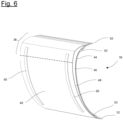
- Figure 6 shows still another leading edge protector 36 having an overall shape similar to the one shown in Fig. 4 , with a lower leg 40.
- the leading edge protector 36 of Fig. 6 is equipped with two lateral boundaries 60 arranged in parallel on the outer surface of the outer top layer 48. They are positioned such that the sling 30 can easily be placed between them.
- the leading edge protector 36 of Fig. 6 comprises two lugs 62 arranged at each lateral side of the leading edge protector 36. These lugs 62 can be used to fasten the leading edge protector 36 to the sling 30.
Landscapes
- Engineering & Computer Science (AREA)
- Mechanical Engineering (AREA)
- Life Sciences & Earth Sciences (AREA)
- Sustainable Development (AREA)
- Sustainable Energy (AREA)
- Chemical & Material Sciences (AREA)
- Combustion & Propulsion (AREA)
- General Engineering & Computer Science (AREA)
- Wind Motors (AREA)
Abstract
Description
- The invention relates to a system for lifting a wind turbine rotor blade.
- Wind turbine rotor blades are large, heavy and fragile parts. Handling wind turbine rotor blades at the manufacturing site, during transportation or at an erection site therefore is difficult and requires specific tools and expertise. In particular when lifting a wind turbine rotor blade to a wind turbine rotor blade hub, great care must be taken to maintain the wind turbine rotor blade in a desired position without causing damage.
- So-called "blade yokes" are large frames with hydraulic pincers designed for gripping a wind turbine rotor blade at opposite sections of the pressure side and the suction side. The blade yokes are fastened to a crane hook and further include means to control an angle of the frame and a gripped wind turbine rotor blade with reference to the horizontal direction. However, these blade yokes are heavy and costly.
- An alternative is provided by supporting the wind turbine rotor blade by simple slings guided around the wind turbine rotor blade's cross-section at a given distance around the blade centre of gravity, usually at the root section and at a midsection. Since state-of-the-art rotor blades are transported and later installed with leading and trailing edge oriented sideways, compression will be applied on these edges during installation by the slings. However, for normal operation rotor blades are designed to withstand loads in flapwise direction, but not in edgewise direction as is the case here. Hence, the slings will most likely damage the wind turbine rotor blade in particular in the midsection where the wind turbine rotor blade has an aerodynamic profile. It is therefore known to place specific protectors at the leading edge and/or at the trailing edge of the wind turbine rotor blade.
- The document
DE 10 2011 113 482 B4 discloses a system for transporting a wind turbine rotor blade with a protector including a trailing edge protector and a leading edge protector fastened to a wind turbine rotor blade by means of two belts connecting both protectors on a pressure side and on a suction side of the blade. The leading edge protector comprises a series of longitudinal contact elements arranged parallel to each other on a tensioning rope and abutting the leading edge. - The document
US 9,016,989 B2 - It is an object of the invention to provide a system for lifting a wind turbine rotor blade that is easy to use when lifting the wind turbine rotor blade with its chord arranged horizontally and that provides sufficient protection.
- This object is solved by the system for lifting a wind turbine rotor blade with the features of claim 1. Aspects of the invention are given in the dependent claims.
- The system for lifting a wind turbine rotor blade comprises
- a wind turbine rotor blade,
- a lifting device having a sling,
- the sling supporting the wind turbine rotor blade at a longitudinal position where the wind turbine rotor blade has an aerodynamic profile, a leading edge, a trailing edge, and a profile chord connecting the leading edge and the trailing edge, wherein the profile chord is arranged horizontally, and
- a leading edge protector arranged between the wind turbine rotor blade and the sling, the leading edge protector having a front portion placed at the leading edge and a lower leg extending from the front portion and placed below the wind turbine rotor blade, wherein
- the front portion and the lower leg are formed as a sandwich construction having an inner top layer, an outer top layer and a core material placed between the inner top layer and the outer top layer, wherein a thickness of the core material, measured between the inner top layer and the outer top layer, increases from a free end of the lower leg towards the front portion in order to reduce a deformation of the wind turbine rotor blade at the leading edge.
- The leading edge protector is designed to protect the leading edge of a wind turbine rotor blade when lifting the same, in particular to the hub of a rotor with horizontal axis mounted at a nacelle arranged at the top of a wind turbine tower. The wind turbine rotor blade may have a blade root which may have a circular cross-section, a blade tip, a longitudinal axis, a suction side surface and a pressure side surface. In operation, the air flows past the wind turbine rotor blade in a direction generally from the leading edge towards the trailing edge. The trailing edge is defined as a line connecting the rearmost points of the aerodynamic profiles, and the leading edge is defined as a line connecting those points of the aerodynamic profiles being farthest away from the rearmost points. A straight line connecting the leading edge and the trailing edge in an aerodynamic profile is the chord of the aerodynamic profile. The pressure side surface and the suction side surface each extend along the wind turbine rotor blades outer surface from the leading edge to the trailing edge.
- The wind turbine rotor blade may comprise a load carrying structure, such as a spar, for example including two spar caps and one or more shear webs placed there between, and aerodynamic outer surfaces formed by skin or shell portions supported by the load carrying structure. The load carrying structure or parts thereof may also be formed integral with the shells. The wind turbine rotor blade may comprise a suction side half shell and a pressure side half shell adhered to each other along the leading edge and along the trailing edge. These half shells may each include at least one spar cap, and one or more shear webs may be placed between the half shells and adhered thereto.
- When lifting the wind turbine rotor blade, it is preferred to arrange the chord more or less horizontally in order to keep wind forces low, in contrast to a vertical alignment of the chord that would cause much stronger wind forces. Thus, either the suction side surface or the pressure side surface of the wind turbine rotor blade points roughly downwards. The feature that the chord is arranged horizontally means that the chord is aligned substantially horizontally. It does not mean the chord is aligned perfectly horizontally, but may include substantial deviations, such as for example up to +/-30°.
- The leading edge protector has a front portion which is placed at the leading edge, and a lower leg which is placed below the wind turbine rotor blade, in particular at an outer surface of the wind turbine rotor blade pointing downwards, either the suction side surface or the pressure side surface. The leading edge protector therefore covers the outer surface of the wind turbine rotor blade in a region around the leading edge. This region in a direction towards the trailing edge extends partly over the suction side surface and/or partly over the pressure side surface, in particular by means of the lower leg arranged below the wind turbine rotor blade.
- The inventors noticed that when lifting a wind turbine rotor blade by means of a sling, large forces are exerted in substantially horizontal direction at the trailing edge and at the leading edge. Their calculations showed that these forces, however, when analysed on a "per surface unit basis", did in most cases not exceed generally accepted limits. Further investigations revealed that the forces exerted by the sling in combination with longitudinal bending of the wind turbine rotor blade, when supported by the sling at a typical longitudinal position, lead to a significant deformation of the wind turbine rotor blade's cross section. It was found that this deformation may lead to failure of the wind turbine rotor blade structure, in particular at the leading edge where an adhesive bond between different structural elements of the wind turbine rotor blade (such as between two half-shells) may be formed.
- In order to reduce the deformation of the wind turbine rotor blade at the leading edge, the leading edge protector is placed between the sling and the wind turbine rotor blade. The leading edge protector, due to the specific sandwich construction of the front portion and the lower leg, forms a unitary, stiff body. To this end, the leading edge protector is provided with a core material having a varying thickness. It is the thickness of the core material that imparts stiffness to the sandwich construction, and by making the core material particularly thick at the front portion and decreasing the thickness towards a free end of the lower leg, an efficient and optimal load distribution is obtained.
- The core material thickness may be selected such that it approximately levels a core material thickness within the rotor blade in a region between the leading edge and a maximum thickness chord position and, thus efficiently distributes the forces exerted by the sling over the complete length of the protector and in such way over a larger surface area of the wind turbine rotor blade covered by the leading edge protector. Since the rotor blade is designed to withstand large bending moments in flap wise direction and lower bending moments in edgewise direction, maximum core material thickness within a profile is usually located at the maximum thickness chord position and lowest to non-existent at the leading edge. Inverting this design rule for the leading edge protector helps to avoid excessive loads on the wind turbine rotor blade's outer surface, in particular at or close to the leading edge, where the wind turbine rotor blade is particularly prone to failure.
- The sandwich construction is particularly lightweight, so that the leading edge protector is easy to handle and transport. This also contributes to a safe lifting process of the wind turbine rotor blade.
- In an aspect, the leading edge protector is shaped such that the inner top layer extends over a defined area of an outer surface of the wind turbine rotor blade and is in contact with the entire defined area. In other words, the leading edge protector is provided with a complimentary shape such that it provides optimal support for the wind turbine rotor blade over the entire area covered by the leading edge protector. This contributes to the desired reduction of any deformation of the wind turbine's cross section. The complementary shape of the inner top layer means the leading edge protector provides optimum protection and support for the wind turbine rotor blade, wherein no gap or almost no gap is present between the inner surface of the inner top layer and the suction side surface and the pressure side surface of the rotor blade.
- In an aspect, the leading edge protector comprises an upper leg which extends from the front portion as an integral part of the sandwich construction and is placed above the wind turbine rotor blade. This means the leading edge protector can be used to protect a wind turbine rotor blade's leading edge, no matter whether it is supported by the sling with its pressure side or its suction side pointing downwards. The upper leg is placed at the wind turbine rotor blade's outer surface which is pointing upwards. The inner top layer and the outer top layer may extend without interruption over both legs and the front portion. The core material may be provided as a continuous layer also extending over both legs and the front portion. In this aspect, the leading edge protector encompasses a larger region of the wind turbine rotor blade's outer surface, including a section of the suction side and a section of the pressure side. This also helps reducing deformation of the wind turbine rotor blade's cross section.
- In an aspect, the thickness of the core material increases from a free end of the upper leg towards the front portion. In other words, the core material thickness will have a maximum value at the front portion and will decrease towards the free ends of both legs. This gives the leading edge protector the necessary shape and strength in the front portion and helps to save weight and material in both leg portions. It also helps to obtain a smooth load distribution at the free end of the upper leg.
- In an aspect, the wind turbine rotor blade at the longitudinal position has a shell structure with a shell thickness, wherein the thickness of the core material of the leading edge protector is selected such that the thickness of the core material at the front portion in combination with the adjacent shell thickness is not less than a maximum thickness of the shell structure in a region covered by the leading edge protector. The shell structure may have a sandwich construction as well and may comprise inner and outer layers of a fibre reinforced composite material and a core material placed therebetween. A main laminate or another comparable reinforcing structure may form an integral part of the shell structure as well. All elements of the shell structure together form the shell thickness, which may vary at the longitudinal position between the leading edge and the trailing edge. Typically, the shell thickness will have a maximum value at or close to the chord position where the aerodynamic profile has a maximum thickness. From there towards the leading edge, the shell thickness typically decreases and reaches a minimum value at or close to the leading edge. The selection of the core material thickness defined in this aspect ensures that the shell structure in combination with the leading edge protector provides sufficient stiffness at the leading edge to avoid or reduce a deformation of the wind turbine rotor blade's cross section. In particular, the change in thickness of the core material from the front portion towards the free end of the lower leg and/or towards the free end of the upper leg may invert a shell thickness distribution of the shell structure in a section covered by the leading edge protector. Such a complimentary increase in core material thickness of the leading edge protector is leading to a nearly levelled combined core material thickness in a combined cross section of the rotor blade shell and the leading edge protector. The stiffening effect then is achieved by the nearly constant thickness of both core materials along the leading edge protector. Ribs or similar stiffening elements are not necessary. At the free end of the upper leg and/or at the free end of the lower leg, the core material may have a minimum thickness which may be for example half of its thickness at the front portion. Preferably, the core material thickness at the free ends is reduced to zero or to almost zero, so that a smooth transition in stiffness towards both free ends is obtained.
- In an aspect, the lower leg is at least twice as long as the upper leg. The length of the upper leg may also be even shorter, so that it covers just a small area of the wind turbine rotor blade's upper surface near the leading edge. It was found that a short upper leg does not only save weight and material, but also supports the positioning of the leading edge protector at the wind turbine rotor blade surface.
- In an aspect, the lower leg and the upper leg have approximately the same length. In general, both the lower leg and the upper leg may have inner surfaces shaped to correspond to the respective outer surfaces of the wind turbine rotor blade. When both legs have approximately the same length, it is possible to use the leading edge protector in both orientations, with either the lower leg or the upper leg placed below the wind turbine rotor blade. Therefore, the wind turbine rotor blade can be supported by the leading edge protector no matter if the pressure side or the suction side points downwards.
- In an aspect, the leading edge protector comprises two parallel lateral boundaries formed on the outer top layer along the lower leg, and the sling is arranged between the lateral boundaries. The boundaries may be formed along lateral sides of the lower leg, for example by laminating one or more additional layers of a fibre material onto the outer top layer, or by attaching boundaries of any other material, such as metal or wood, to the outer top layer. The lateral boundaries run in parallel and have a distance to each other which is sufficiently wide for placing the sling therein between. The lateral boundaries help to prevent the sling from slipping off from the leading edge protector.
- In an aspect, the leading edge protector comprises a plurality of lugs extending from lateral sides of the leading edge protector. The lugs may for example be formed by the inner top layer and/or by the outer top layer, or by additional members attached thereto. When the leading edge protector is placed at the wind turbine rotor blade, the lugs are accessible for fastening a belt or rope thereto, wherein the belt or rope may be used in particular to fasten the leading edge protector to the sling. This is a simple and efficient means to prevent the leading edge protector from falling down when the sling is removed from a wind turbine rotor blade.
- In an aspect, the inner top layer comprises a cover layer of a soft, elastic material. In particular, a layer of rubber may be used. The softness and elasticity of the material helps to protect the wind turbine rotor blades' outer surface, in particular in view of manufacturing tolerances and variations of the actual position where the leading edge protector is applied to a given wind turbine rotor blade geometry. A rubber layer helps to level blade surface tolerances and also provides friction.
- In an aspect, the inner top layer and/or the outer top layer comprises a fibre reinforced composite material. In general, the top layers can also be formed by other materials providing sufficient stability, such as sheet metal. However, a fibre reinforced composite material provides excellent stiffness at reduced weight and also provides a surface compatible with the surface of a wind turbine rotor blade. Therefore, a lightweight, strong and durable construction is obtained.
- In an aspect, the fibre reinforced composite material includes reinforcing fibres arranged at angles of 0°, 90°, +45° and -45° with reference to a longitudinal direction of the lower leg. This helps to obtain a particularly stiff structure with high torsional stability.
- In an aspect, the core material comprises balsa wood. In general, any suitable core material may be used, for example a foamed plastics material such as polyethylene. Balsa wood is a lightweight material with excellent stiffness properties resulting in a robust and stiff design.
- In an aspect, the lower leg extends up to a chord position of the wind turbine rotor blade where the aerodynamic profile has a maximum thickness. At this chord position, the wind turbine rotor blade exhibits a particularly stiff structure, such as a main laminate of a half shell and/or a main spar cap. Extending the lower leg up to this chord position therefore helps to transfer loads into the load carrying structure of the wind turbine rotor blade and thus to avoid excessive forces and/or deformation at the leading edge.
- In an aspect, the lifting device comprises a longitudinal beam, at least one cross-beam attached to the longitudinal beam and a release mechanism, wherein the sling is connected to the cross-beam and the release mechanism is adapted to open the sling and/or to disconnect one end of the sling from the cross-beam. The release mechanism makes it easy to release a wind turbine rotor blade supported by the lifting device. In particular, this can be performed easily by means of the release mechanism once the wind turbine rotor blade has been attached to a hub. In particular, the leading edge protector may be fastened to the sling and/or to the cross-beam or any other member of the lifting device to prevent the leading edge protector from falling down.
- In the following, the invention is explained in greater detail based on embodiments shown in drawings. The figures show:
- Fig. 1
- a wind turbine rotor blade supported by a lifting device shown in a perspective view,
- Fig. 2
- a wind turbine rotor blade supported by a sling without a leading edge protector (a) and with a leading edge protector (b) shown in cross-section,
- Fig. 3
- a wind turbine rotor blade in a neutral state (a) and when supported by a sling without a leading edge protector (b) and with a leading edge protector (c) shown in cross-section,
- Fig. 4
- a leading edge protector shown in a perspective view,
- Fig. 5
- another leading edge protector shown in a perspective view, and
- Fig. 6
- still another leading edge protector shown in a perspective view.
-
Figure 1 shows a windturbine rotor blade 10 fastened to alifting device 12. The windturbine rotor blade 10 has acircular blade root 14, ablade tip 16, a leading edge 18 (not visible infigure 1 ), a trailingedge 20, asuction side 22 pointing downwards and apressure side 24 pointing upwards. The windturbine rotor blade 10 has a length of about 80 m or more. Its longitudinal axis and a profile chord 64 (seeFig. 3 ) are arranged horizontally. - The lifting
device 12 comprises alongitudinal beam 26 arranged parallel to the longitudinal axis of the windturbine rotor blade 10 and extending over about one quarter of the wind turbine rotor blades' length. At each of the two ends of thelongitudinal beam 26, the lifting device includes ashorter cross-beam 28. The liftingdevice 12 further comprises twoslings 30. Eachsling 30 is guided around the wind turbine rotor blades' cross-section so that a central section of eachsling 30 is placed below the windturbine rotor blade 10, at thesuction side 22 thereof. Further, eachsling 30 has two free ends attached to one end of the correspondingcross-beam 28. A midsection of thelongitudinal beam 26 is provided with achain 32 or comparable attachment means for connecting to a hook of a crane. - The wind
turbine rotor blade 10 is positioned in thelifting device 12 such that the wind turbine rotor blades' centre of gravity lies below a midpoint of thelongitudinal beam 26. This means that one of theslings 30 is positioned relatively close to theblade root 14 and the other one of theslings 30 is arranged at a longitudinal position approximately at a midsection of the windturbine rotor blade 10. Thesling 30 closer to theblade root 14 supports a cross-section already having an aerodynamic profile but with a large relative thickness. - At the longitudinal position supported by the other one of the
slings 30, the windturbine rotor blade 10 has an aerodynamic profile shown in cross-section inFig. 2a and 2b . InFig. 2a , the windturbine rotor blade 10 is shown supported by asling 30 without a leading edge protector. The wind turbine rotor blade's cross-section is formed by two half shells adhered to each other at theleading edge 18 and at the trailingedge 20. Theprofile chord 64 is a straight line connecting the leadingedge 18 and the trailingedge 20. At the trailingedge 20, the cross-section comprises aflat element 54 forming a so-called flatback profile. The varying thickness of the half shells shows that the half shells are formed as sandwich constructions themselves, comprising a core material extending over a majority of the half shells' widths. Only at theleading edge 18 and close to the trailingedge 20, the half shells consist of a solid, relatively thin laminate of a fibre reinforced plastics material. Ashell thickness 66 is indicated for both half shells at a chord position where theshell thickness 66 has a maximum value. - At a chord position where the aerodynamic profile has its maximum thickness, both half shells are supported by a
spar cap 32 formed integral with the respective half shell. Between these spar caps 32, ashear web 34 is placed and adhered to both spar caps 32, thereby forming a central load carrying structure. - The arrows shown at the
leading edge 18 and below a front portion of thesuction side 22 illustrate the forces exerted by thesling 30 onto the wind turbine rotor blade's outer surface. One can see that excessive loads are applied to the leadingedge 18 which is a particularly fragile portion of the wind turbine rotor blade's cross-section, where the relatively thin-walled half shells are adhered together. At the chord's central portion, below thespar cap 32 of the suction side half shell, where the wind turbine rotor blades' outer surface is most stiff, only much lower forces are applied. - In
Fig. 2b , the same windturbine rotor blade 10 is shown supported bysling 30 but with aleading edge protector 36 placed between the windturbine rotor blade 10 and thesling 30. Theleading edge protector 36 has afront portion 38 and alower leg 40. One can see in the cross-section shown that a thickness of theleading edge protector 36 is largest at thefront portion 38 placed at theleading edge 18, and decreases from there continuously along thelower leg 40, towards the leading edge protector's lowermost and leftmost end which is positioned right below thespar cap 32 of thesuction side 22. The arrows again illustrate the forces exerted onto the wind turbine rotor blades' outer surface (although for illustrative purposes, the arrow's tips end at thesling 30, not on the wind turbine rotor blades' outer surface). The forces are distributed in a much more even manner by means of theleading edge protector 36. -
Figures 3a, 3b and 3c each show a cross section of the windturbine rotor blade 10, drawn at the same longitudinal position in different load scenarios. The elements of the windturbine rotor blade 10 are depicted with the same reference numerals as inFig. 2 . In contrast toFig. 2 , the windturbine rotor blade 10 has twoshear webs 34 and is positioned with thesuction side 22 pointing upwards. Theprofile chord 64 is arranged horizontally. To better illustrate the deformation of the windturbine rotor blade 10 in different load scenarios, the cross section is drawn in arectangular box 68 having the same size in each of theFigures 3a, 3b and 3c and deformations are exaggerated. -
Figure 3a shows the windturbine rotor blade 10 in a neutral state without any loads. The aerodynamic profile is not deformed and has its regular shape. Theshear webs 34 are arranged exactly vertically, thesuction side 22 has a smooth, convex curvature. The leadingedge 18 is positioned at amidline 70 of therectangular box 68. -
Figure 3b shows the windturbine rotor blade 10 when supported by a sling 30 (not shown) applied directly below the windturbine rotor blade 10, without aleading edge protector 36. The cross section is deformed significantly: The smooth convex curvature of thesuction side 22 is no longer there in particular in a rear part close to theshear web 34 arranged near the trailingedge 20, where thesuction side 22 even has a concave curvature. Both shearwebs 34 are inclined with reference to the vertical direction. The inclination of theflat element 54 formed at the trailingedge 20 has changed its direction as compared toFig. 3a . Most importantly, the leadingedge 18 was pressed upward- and inwardly, so that it is no longer at the height of themidline 70, but significantly above. In this context, a radius of curvature of the aerodynamic profile at theleading edge 18 is much smaller inFig. 3b than inFig. 3a . This deformation at theleading edge 18 is likely to damage the windturbine rotor blade 10. - In
Fig. 3c , the windturbine rotor blade 10 is supported by asling 30 with aleading edge protector 36 placed between the windturbine rotor blade 10 and thesling 30. Theleading edge protector 36 and thesling 30 are not shown inFig. 3c , but are placed as is illustrated inFig. 2b . One can see there still is some deformation, both shearwebs 34 and theflat element 54 are still inclined as compared toFig. 3a . However, the deformation at theleading edge 18 is much less than inFig. 3b . In particular, the radius of curvature of the aerodynamic profile at theleading edge 18 is similar to the neutral state shown inFig. 3c , so that the windturbine rotor blade 10 will not be damaged. -
Figure 4 shows theleading edge protector 36 ofFig. 2b in isolation. It has afront portion 38 and alower leg 40. These elements are formed as a sandwich construction comprising an innertop layer 44, acore material 46 and an outertop layer 48. Thecore material 46 has a thickness measured between the innertop layer 44 and the outertop layer 48, the thickness having a maximum value at thefront portion 38 and decreasing continuously from there to zero at afree end 50 of theupper leg 42 and at afree end 52 of thelower leg 40. - The inner
top layer 44, the outertop layer 48 and thecore material 46 each extend over the entire way from thefree end 50, along theupper leg 42, over thefront portion 38 and along thelower leg 40 towards thefree end 52. At the outer side of the innertop layer 44, a soft,elastic rubber layer 56 is provided. It covers the entire surface of the innertop layer 44. Awidth 58 of theleading edge protector 36 is measured along the direction of the leadingedge 18 and is approximately constant over the entireleading edge protector 36. -
Figure 5 shows anotherleading edge protector 36 of similar construction as theleading edge protector 36 ofFig. 4 , but with alower leg 40 and anupper leg 42 having approximately the same length. In particular, bothlegs turbine rotor blade 10 has a maximum thickness. This means theleading edge protector 36 ofFig. 5 can be used to protect a wind turbine rotor blade's leadingedge 18, no matter whether it is supported by theslings 30 with itspressure side 24 or itssuction side 22 pointing downwards. -
Figure 6 shows still anotherleading edge protector 36 having an overall shape similar to the one shown inFig. 4 , with alower leg 40. Theleading edge protector 36 ofFig. 6 is equipped with twolateral boundaries 60 arranged in parallel on the outer surface of the outertop layer 48. They are positioned such that thesling 30 can easily be placed between them. Further, the leadingedge protector 36 ofFig. 6 comprises twolugs 62 arranged at each lateral side of theleading edge protector 36. Theselugs 62 can be used to fasten theleading edge protector 36 to thesling 30. -
- 10
- wind turbine rotor blade
- 12
- lifting device
- 14
- blade root
- 16
- blade tip
- 18
- leading edge
- 20
- trailing edge
- 22
- suction side
- 24
- pressure side
- 26
- longitudinal beam
- 28
- cross-beam
- 30
- sling
- 32
- spar cap
- 34
- web
- 36
- leading edge protector
- 38
- front portion
- 40
- lower leg
- 42
- upper leg
- 44
- inner top layer
- 46
- core material
- 48
- outer top layer
- 50
- free end of upper leg
- 52
- free end of lower leg
- 54
- flat element
- 56
- rubber layer
- 58
- width
- 60
- lateral boundary
- 62
- lug
- 64
- chord
- 66
- shell thickness
- 68
- box
- 70
- midline
Claims (15)
- A system for lifting a wind turbine rotor blade (10), comprising• a wind turbine rotor blade (10),• a lifting device (12) having a sling (30),• the sling (30) supporting the wind turbine rotor blade (10) at a longitudinal position where the wind turbine rotor blade (10) has an aerodynamic profile, a leading edge (18), a trailing edge (20), and a profile chord (64) connecting the leading edge (18) and the trailing edge (20), wherein the profile chord (64) is arranged horizontally, and• a leading edge protector (36) arranged between the wind turbine rotor blade (10) and the sling (30), the leading edge protector (36) having a front portion (38) placed at the leading edge (18) and a lower leg (40) extending from the front portion (38) and placed below the wind turbine rotor blade (10), characterised in that• the front portion (38) and the lower leg (40) are formed as a sandwich construction having an inner top layer (44), an outer top layer (48) and a core material (46) placed between the inner top layer (44) and the outer top layer (48), wherein a thickness of the core material (46), measured between the inner top layer (44) and the outer top layer (48), increases from a free end of the lower leg (40) towards the front portion (38) in order to reduce a deformation of the wind turbine rotor blade (10) at the leading edge (18).
- The system of claim 1, characterised in that the leading edge protector (36) is shaped such that the inner top layer (44) extends over a defined area of an outer surface of the wind turbine rotor blade (10) and is in contact with the entire defined area.
- The system of claim 1 or 2, characterised in that the leading edge protector (36) comprises an upper leg (42) which extends from the front portion (38) as an integral part of the sandwich construction and is placed above the wind turbine rotor blade (10).
- The system of claim 3, characterised in that the thickness of the core material (46) increases from a free end (50) of the upper leg (42) towards the front portion (38).
- The system of any of the claims 1 to 4, characterised in that the wind turbine rotor blade (10) at the longitudinal position has a shell structure with a shell thickness, wherein the thickness of the core material (46) of the leading edge protector (36) is selected such that the thickness of the core material (46) at the front portion (38) in combination with the adjacent shell thickness is not less than a maximum thickness of the shell structure in a region covered by the leading edge protector (36).
- The system of any of the claims 3 to 5, characterised in that the lower leg (40) is at least twice as long as the upper leg (42).
- The system of any of the claims 3 to 5, characterised in that the lower leg (40) and the upper leg (42) have approximately the same length.
- The system of any of the claims 1 to 7, characterised in that the leading edge protector (36) comprises two parallel lateral boundaries (60) formed on the outer top layer (48) along the lower leg (40), and the sling (30) is arranged between the lateral boundaries (60).
- The system (36) of any of the claims 1 to 8, characterised in that the leading edge protector (36) comprises a plurality of lugs (62) extending from lateral sides of the leading edge protector (36).
- The system of any of the claims 1 to 9, characterised in that the inner top layer (44) comprises a cover layer of a soft, elastic material.
- The system of any of the claims 1 to 10, characterised in that the inner top layer (44) and/or the outer top layer (48) comprises a fibre reinforced composite material.
- The system of claim 11, characterised in that the fibre reinforced composite material includes reinforcing fibres arranged at angles of 0°, 90°, +45° and -45° with reference to a longitudinal direction of the lower leg (40).
- The system of any of the claims 1 to 12, characterised in that the core material (46) comprises balsa wood.
- The system of any of the claims 1 to 13, characterised in that the lower leg (40) extends up to a chord position of the wind turbine rotor blade (10) where the aerodynamic profile has a maximum thickness.
- The system of any of the claims 1 to 14, characterised in that the lifting device (12) comprises a longitudinal beam (26), at least one cross-beam (28) attached to the longitudinal beam (26) and a release mechanism, wherein the sling (30) is connected to the cross-beam (28), and the release mechanism is adapted to open the sling (30) and/or to disconnect one end of the sling (30) from the cross-beam (28).
Priority Applications (2)
| Application Number | Priority Date | Filing Date | Title |
|---|---|---|---|
| EP22156738.1A EP4227525A1 (en) | 2022-02-15 | 2022-02-15 | A system for lifting a wind turbine rotor blade |
| US18/165,087 US12312215B2 (en) | 2022-02-15 | 2023-02-06 | System for lifting a wind turbine rotor blade |
Applications Claiming Priority (1)
| Application Number | Priority Date | Filing Date | Title |
|---|---|---|---|
| EP22156738.1A EP4227525A1 (en) | 2022-02-15 | 2022-02-15 | A system for lifting a wind turbine rotor blade |
Publications (1)
| Publication Number | Publication Date |
|---|---|
| EP4227525A1 true EP4227525A1 (en) | 2023-08-16 |
Family
ID=80682489
Family Applications (1)
| Application Number | Title | Priority Date | Filing Date |
|---|---|---|---|
| EP22156738.1A Pending EP4227525A1 (en) | 2022-02-15 | 2022-02-15 | A system for lifting a wind turbine rotor blade |
Country Status (2)
| Country | Link |
|---|---|
| US (1) | US12312215B2 (en) |
| EP (1) | EP4227525A1 (en) |
Families Citing this family (1)
| Publication number | Priority date | Publication date | Assignee | Title |
|---|---|---|---|---|
| CN117780552A (en) * | 2023-11-12 | 2024-03-29 | 江苏麦吉嘉智能科技有限公司 | A wind turbine blade anti-vibration self-falling protection component |
Citations (6)
| Publication number | Priority date | Publication date | Assignee | Title |
|---|---|---|---|---|
| US20120098283A1 (en) * | 2009-04-29 | 2012-04-26 | Karl Aage Maj | Blade lifting system with saloon doors |
| DE102011113482B4 (en) | 2011-09-13 | 2013-04-18 | Nordex Energy Gmbh | Protective device for a rotor blade of a wind energy plant |
| WO2013091655A1 (en) * | 2011-12-21 | 2013-06-27 | Vestas Wind Systems A/S | Blade lifting sling and method of use thereof |
| US20150028610A1 (en) * | 2013-07-29 | 2015-01-29 | Siemens Aktiengesellschaft | Blade gripping device |
| US9016989B2 (en) | 2013-07-30 | 2015-04-28 | General Electric Company | Protective cap for a rotor blade |
| DE102018000372A1 (en) * | 2018-01-18 | 2019-07-18 | Senvion Gmbh | Device for attaching a crane or guide rope to a rotor blade of a wind power plant |
Family Cites Families (1)
| Publication number | Priority date | Publication date | Assignee | Title |
|---|---|---|---|---|
| US4039217A (en) * | 1969-12-19 | 1977-08-02 | Bryant John G | Clutch pads |
-
2022
- 2022-02-15 EP EP22156738.1A patent/EP4227525A1/en active Pending
-
2023
- 2023-02-06 US US18/165,087 patent/US12312215B2/en active Active
Patent Citations (6)
| Publication number | Priority date | Publication date | Assignee | Title |
|---|---|---|---|---|
| US20120098283A1 (en) * | 2009-04-29 | 2012-04-26 | Karl Aage Maj | Blade lifting system with saloon doors |
| DE102011113482B4 (en) | 2011-09-13 | 2013-04-18 | Nordex Energy Gmbh | Protective device for a rotor blade of a wind energy plant |
| WO2013091655A1 (en) * | 2011-12-21 | 2013-06-27 | Vestas Wind Systems A/S | Blade lifting sling and method of use thereof |
| US20150028610A1 (en) * | 2013-07-29 | 2015-01-29 | Siemens Aktiengesellschaft | Blade gripping device |
| US9016989B2 (en) | 2013-07-30 | 2015-04-28 | General Electric Company | Protective cap for a rotor blade |
| DE102018000372A1 (en) * | 2018-01-18 | 2019-07-18 | Senvion Gmbh | Device for attaching a crane or guide rope to a rotor blade of a wind power plant |
Also Published As
| Publication number | Publication date |
|---|---|
| US20230257234A1 (en) | 2023-08-17 |
| US12312215B2 (en) | 2025-05-27 |
Similar Documents
| Publication | Publication Date | Title |
|---|---|---|
| EP2318702B1 (en) | Wind turbine rotor blade with extension portion having a skin located over a framework | |
| EP2396540B1 (en) | A rotor blade for a wind turbine and a method for making the same | |
| US8186964B2 (en) | Spar assembly for a wind turbine rotor blade | |
| EP2915996B1 (en) | Wind turbine blade with viscoelastic damping | |
| EP2526288B1 (en) | Segmented rotor blade extension portion | |
| US20110142662A1 (en) | Spar Cap Assembly for a Wind Turbine Rotor Blade | |
| EP2526287B1 (en) | A wind turbine rotor blade having a buckling trailing edge | |
| CN106536919A (en) | Modular system for transporting wind turbine blades | |
| WO2022194333A1 (en) | A pitch controlled wind turbine with blade connecting members and split blades | |
| US12312215B2 (en) | System for lifting a wind turbine rotor blade | |
| EP3002452B1 (en) | A wind turbine blade | |
| EP2518314B1 (en) | Wind turbine rotor blade and wind turbine | |
| US20150267681A1 (en) | Wind turbine having external gluing flanges near flat back panel | |
| AU2011226066B2 (en) | Wind turbine rotor blade | |
| EP4157620B1 (en) | Method for manufacturing a wind turbine blade and wind turbine blade obtained thereby | |
| EP3892849B1 (en) | Wind turbine rotor blade having a shear web | |
| EP4363711B1 (en) | A wind turbine blade | |
| US20240167450A1 (en) | A wind turbine blade | |
| CN116601384A (en) | Wind turbine blade with buckling-resistant spar caps | |
| EP4077914B1 (en) | Wind turbine blade | |
| EP3186502A1 (en) | A wind turbine blade, and a method of reinforcing a wind turbine blade |
Legal Events
| Date | Code | Title | Description |
|---|---|---|---|
| PUAI | Public reference made under article 153(3) epc to a published international application that has entered the european phase |
Free format text: ORIGINAL CODE: 0009012 |
|
| STAA | Information on the status of an ep patent application or granted ep patent |
Free format text: STATUS: THE APPLICATION HAS BEEN PUBLISHED |
|
| AK | Designated contracting states |
Kind code of ref document: A1 Designated state(s): AL AT BE BG CH CY CZ DE DK EE ES FI FR GB GR HR HU IE IS IT LI LT LU LV MC MK MT NL NO PL PT RO RS SE SI SK SM TR |
|
| STAA | Information on the status of an ep patent application or granted ep patent |
Free format text: STATUS: REQUEST FOR EXAMINATION WAS MADE |
|
| 17P | Request for examination filed |
Effective date: 20240215 |
|
| RBV | Designated contracting states (corrected) |
Designated state(s): AL AT BE BG CH CY CZ DE DK EE ES FI FR GB GR HR HU IE IS IT LI LT LU LV MC MK MT NL NO PL PT RO RS SE SI SK SM TR |