EP4227488A1 - Sensor system of underground mining vehicles and underground mining vehicle comprising sensor system - Google Patents
Sensor system of underground mining vehicles and underground mining vehicle comprising sensor system Download PDFInfo
- Publication number
- EP4227488A1 EP4227488A1 EP22156249.9A EP22156249A EP4227488A1 EP 4227488 A1 EP4227488 A1 EP 4227488A1 EP 22156249 A EP22156249 A EP 22156249A EP 4227488 A1 EP4227488 A1 EP 4227488A1
- Authority
- EP
- European Patent Office
- Prior art keywords
- movable plate
- underground mining
- section
- fastened
- mining vehicle
- Prior art date
- Legal status (The legal status is an assumption and is not a legal conclusion. Google has not performed a legal analysis and makes no representation as to the accuracy of the status listed.)
- Granted
Links
Images



Classifications
-
- E—FIXED CONSTRUCTIONS
- E21—EARTH OR ROCK DRILLING; MINING
- E21C—MINING OR QUARRYING
- E21C35/00—Details of, or accessories for, machines for slitting or completely freeing the mineral from the seam, not provided for in groups E21C25/00 - E21C33/00, E21C37/00 or E21C39/00
- E21C35/04—Safety devices
-
- E—FIXED CONSTRUCTIONS
- E21—EARTH OR ROCK DRILLING; MINING
- E21C—MINING OR QUARRYING
- E21C35/00—Details of, or accessories for, machines for slitting or completely freeing the mineral from the seam, not provided for in groups E21C25/00 - E21C33/00, E21C37/00 or E21C39/00
- E21C35/08—Guiding the machine
Definitions
- the present invention relates to sensor systems of underground mining vehicles and underground mining vehicles comprising a sensor system.
- Underground mining vehicles operate in harsh conditions undergrounds where is dark, roads are narrow, and the road network is constantly changing. Due to poor visibility, it is hard to see people, other machines or any other obstacles, e.g. loose rocks, on the road and the underground mining vehicle may be damaged if it runs into an obstacle. Further, the underground mining vehicles are big, and the operator's view from the cab is therefore restricted. Especially right next to the underground mining vehicle. Therefore, underground mining vehicles may comprise sensors to help the operator to see or be aware of the surroundings of the vehicle. Even if the underground mining vehicle has sensors, it is still possible to hit obstacles on the road or walls or ceiling of the mine. Due the collision, the sensors may break or at least their position may change, and they may be useless after the collision.
- the objective of the system is to alleviate the disadvantages mentioned above.
- the present invention provides a system for protecting a sensor fastened to the underground mining vehicle.
- the sensor system of underground mining vehicles which system is arranged to be fastened at a perimeter of an underground mining vehicle, comprising a sensor and a stand, wherein the stand comprises a mounting plate for fastening the stand to the underground mining vehicle; a movable plate, having an inner end and an outer end, fastened moveably to the mounting plate; a guard member comprising a rim, which guard member is provided at the outer end so that the rim extends over the outer end of the movable plate; and a biasing member fastened between the movable plate and the mounting plate.
- the sensor is fastened to the movable plate so that the sensor is between the rim of the guard member and the inner end of the movable plate.
- the movable plate has two positions: a resting position, wherein the rim of the guard member is extending outside of the underground vehicle perimeter when the system is fastened to the underground mining vehicle, and a retracted position, wherein the outer end and the sensor are retracted inside the perimeter of the underground mining vehicle when the system is fastened to the underground mining vehicle, and the biasing member is biasing the movable plate to the resting position.
- the advantage of the system is that the underground mining vehicle operator has better visibility and/or understanding of the surroundings of the vehicle as the system may be fastened to the underground mining vehicle so that the sensor is outside of the perimeter of the vehicle while the sensor is protected from external impacts.
- the senor is outside the perimeter of the underground mining vehicle when the movable plate is in the resting position.
- the biasing member is a mechanical spring.
- the biasing member is made of rubber.
- the biasing member comprises a hydraulic cylinder or a pneumatic cylinder.
- the guard member is a wheel fastened to the movable plate with an axle perpendicular to the movable plate.
- the movable plate is arranged to move linearly between the resting position and the retracted position on top of the mounting plate.
- the movable plate comprises at least two sections, a first section being parallel to the mounting plate, and a second section being perpendicular to the first section.
- the movable plate comprises a third section, which is parallel to the first section, and the second section is arranged between the first section and the third section.
- the mounting plate comprises a perpendicular part
- the biasing member is arranged between the perpendicular part and the second section of the movable plate.
- the stand comprises guiding means for guiding the movement of the movable plate between the resting position and the retracted position.
- the guiding means comprises at least one elongated opening in the mounting plate and fastening means for fastening the movable plate to the mounting plate, wherein the fastening means are configured to extend from the movable plate through the at least one elongated opening.
- the guiding means comprises an elongated rod extending from the second section of the movable plate and a hole in the perpendicular part of the mounting plate, wherein the elongated rod extends from the second section through the hole in the perpendicular part.
- the movable plate together with the guard member and the sensor fastened to the movable plate, is arranged to move towards the retracted position when the rim is subjected to an external force exceeding the biasing force of the biasing member.
- the present invention provides as underground mining vehicle comprising a sensor system described herein.
- the system described herein is an sensor system of underground mining vehicles.
- the underground mining vehicle may be a mine machine or a construction machine e.g. a rock drilling rig, a development drill, a tunneling drilling machine, a surface drilling machine, a bolting or reinforcing vehicle, a rock removal machine, a long hole drill rig, an explosive charging machine, a loader, a transport vehicle, a loading machine, or hauling machine, setting vehicle of gallery arcs or nets, a concrete spraying machine, a crusher, a measuring vehicle, a passenger transport vehicle, or a loading or a hauling machine.
- the common feature for all these vehicles is that they are designed to operate in harsh conditions underground, wherein the road network is continuously changing.
- term vehicle is used but it should be understood as an underground mining vehicle described herein.
- the sensor system comprising a sensor 1 and a stand 2, is configured to be fastened to the underground mining vehicle at, i.e. in close proximity, a perimeter of the underground mining vehicle so that the system extends over the perimeter of the vehicle, i.e. the outer edge of the system is outside of the perimeter of the vehicle and inner edge of the system is inside the perimeter of the vehicle. Consequently, the sensor 1 may extend over the perimeter of the vehicle and, therefore, provide unrestricted visibility around the vehicle.
- the system comprises also a guard member 7a, 7b,..., which extends further outside the perimeter of the vehicle than the sensor, when the system is fastened to the vehicle.
- the system may be fastened to a fender of the vehicle.
- the fender may be for example front or rear bumber, or it may be a wheel fender.
- the stand 2 of the sensor system comprises a mounting plate 3 for fastening the stand 2 to the vehicle, a movable plate 4 fastened moveably to the mounting plate 3, a guard member 7a, 7b,... at the outer end of the movable plate 4, and a biasing member 9a, 9b,... fastened between the movable plate 4 and the mounting plate 3.
- Fastened between the movable plate and the mounting plate should be understood as fastened to the biasing member is fastened to the movable plate and the mounting plate so, that the biasing member is able to act between these components, i.e. the plates may subject forces to the biasing member and vice versa.
- the movable plate 4 has an inner end 5, which is the end towards the center of the vehicle when the system is fastened to the vehicle, and an outer end 6, which is opposite to the inner end 5.
- the guard member 7a, 7b,... comprises a rim 8, which is pointing outwards of the vehicle, when the system is fastened to the vehicle.
- the movable plate 4 may be a thin plate, bended plate, or any part which may be fastened to the mounting plate 3.
- the guard member 7a, 7b,... is provided at the outer end of the movable plate 4, i.e. it is in proximity to the outer end 6 so that the rim 8 extends over the outer end 6 of the movable plate 4.
- the guard member may be fastened to the movable plate or it may be integral part of the movable plate.
- the fastening point of the guard member depends on the size of the guard member. Therefore, the proximity to the outer end means that the fastening point of the guard member is closer to the outer end than the inner end of the movable plate.
- the biasing member 9a, 9b,... is fastened between the movable plate 4 and the mounting plate 3.
- the biasing member 9a, 9b,... may be any means capable of being extended, compressed or pivoted to provide the force for biasing the movable plate relative to the mounting plate.
- suitable biasing member would include various springs such as mechanical springs, e.g. coiled, coil compression, spiral, retractable, leaf or torsion spring, pneumatic cylinder/piston arrangements, lengths of resilient material such as rubber or other elastic material, etc.
- the movable plate 4 has two positions: a resting position, wherein the rim 8 of the guard member 7a, 7b,... is extending outside of the underground vehicle perimeter when the system is fastened to the underground mining vehicle, and a retracted position, wherein the outer end 6 of the movable plate 4 and the sensor 1 are retracted inside the perimeter of the underground mining vehicle when the system is fastened to the underground mining vehicle.
- the movable plate 4 is in resting position and the rim 8 of the guard member is outside of the perimeter of the vehicle. If the guard member 7a, 7b,... is subjected to an external force, e.g.
- the movable plate 7 and the components attached to it would move towards the retracted position.
- the external force should exceed the biasing force of the biasing member to move the movable plate towards or to the retracted position.
- the biasing force of the biasing member will bias, i.e. push, the movable plate back to the resting position.
- the sensor 1 of the system may be for example a vision-based sensor, e.g. camera or other machine vision-based sensor, a scanner, or a radar.
- the sensor may be located outside of the perimeter of the vehicle, when the system is fastened to the vehicle and the movable plate is in resting position.
- the guard member may be a wheel 7a rotatable around an axis perpendicular to the movement of the movable plate; a fixed block 7b, e.g. made of non-elastic or elastic material, such as rubber, which may have a curved rim; or a section of the movable plate forming outer edge of the movable plate.
- the movable plate 4 may move linearly between the resting position and the retracted position on top of the mounting plate, i.e. moving along a straight line.
- the movement may be non-linear, e.g. rotational.
- the movable plate 4 may comprise a first section 41, which is parallel to the mounting plate 3. All components fastened to the movable plate 4 may be fastened to the first section 41.
- the first section 41 of the movable plate is moveably fastened to the mounting plate 3.
- the movable plate 4 may comprise a second section 42, that is perpendicular to the first section 41.
- Some of the components of the system may be fastened to the first section 41 and some of the components may be fastened to the second section 42.
- the sensor 1 and the guard member 7a, 7b,... may be fastened to the first section 41
- the biasing member 9a, 9b,... may be fastened to the second section 42.
- all the components are fastened to the first section 41.
- the movable plate 4 may comprise a third section 43, which is parallel to the first section 41, and the second section 42 is between the first section 41 and the third section 43, i.e. the movable plate is a U-shaped plate.
- the guard member 7a, 7b,... may be fastened between the first section 41 and the third section 43.
- the mounting plate 3 is for example an elongated plate having a first surface, on which the movable plate 4 is fastened, a second surface on the opposite side of the plate, long sides, and short sides.
- the second surface of the mounting plate is the mounting surface which is fastened to the vehicle.
- the mounting plate may be fastened to the vehicle with fastening means that may be fastened to the first surface.
- the mounting plate 3 may comprise a perpendicular part 31, which may be a bended section or a separate perpendicular part.
- the biasing member 9a, 9b,... may be fastened between the perpendicular part 31 and the movable plate 4, e.g. the second section 42 of the movable plate.
- the perpendicular part 31 may comprise a hole 15, which is used for guiding the movement of the movable plate 4.
- the system may comprise guiding means 12, 13(a, b,...), 14, 15 for guiding the movement of the movable plate 4.
- the guiding means may comprise at least one opening 12 in the mounting plate 3, fastening means 13a, 13b,... for fastening the movable plate 4 to the mounting plate 3, and/or a rod 14 extending from the movable plate through the hole 15 in the perpendicular part 31 of the mounting plate 3.
- the opening 12 may be elongated opening or openings arranged in parallel direction to the long sides of the mounting plate.
- the mounting plate 3 may comprise more than one opening.
- the fastening means may comprise at least one pin, bolt or screw 13a, that extends from the movable plate 4 through at least one opening 12 in the mounting plate3.
- the pin may comprise threads.
- the movable plate 4, e.g. the first section 41, may comprise opening and the pin, bolt or screw 13a is provided through the opening on the movable plate and the opening 12 in the mounting plate.
- the pin, bolt or screw 13a may comprise a head and a nut 13b, wherein the nut is fastened to the other end of the pin, bolt, or screw, and the movable plate and the mounting plate are arranged between the head and the nut.
- head the pin, bolt or screw may comprise another nut in the other end.
- the fastening means may comprise two or more pins, bolts or screws, and the mounting plate comprises the same number of openings through which the pins, bolts, or screws are fastened.
- There may be a washer or washers in conjunction with the pin, bolt or screw so that the washer(s) are between the movable plate and the mounting plate.
- washers may be provided in conjunction with the pin, bolt, or screw so that the washers are between the head of the pin, bolt or screw and the movable plate and/or between the nut and the mounting plate.
- Figure 1 shows an embodiment of the stand 2 of the sensor system.
- the stand comprises a mounting plate 3 and a movable plate 4 fastened moveably to the mounting plate 3.
- the mounting plate 3 is an elongated sheet, which may be made of metal.
- the mounting plate 3 comprises a base section comprising the surface to which the movable plate 4 is fastened.
- the mounting plate 3 comprises a perpendicular part 31 which is perpendicular to the base section.
- the perpendicular part 31 is a separate component fastened to the base section.
- the separate perpendicular part 31 is fastened to the mounting plate 3 by bolts, but optionally, it may be fastened by welding or adhesive or other mechanical means.
- the movable plate 4 is an elongated sheet, which is fastened to the mounting plate 3 moveably, i.e. the movable plate 4 is fastened to the mounting plate 3 but it may move in relation to the mounting plate 3.
- the movable plate 4 comprises a first section 41, that is parallel to the base section of the mounting plate 3, a second section 42 perpendicular to the first section 41, and a third section 43 parallel to the first section 41.
- the second section 42 is between the first section 41 and third section 43.
- the stand 2 comprises a guard member fastened to the movable plate.
- the guard member in embodiment of figure 1 is a wheel 7a, which is rotatable about an axle 16 perpendicular to the movable plate 4.
- the wheel 7a is fastened between the first section 41 and the third section 43 of the movable plate by the axle 16.
- the wheel 7a comprises a rim 8, which is defined by perimeter of the wheel 7a.
- the stand 2 comprises a biasing member between the movable plate 4 and the mounting plate 3.
- the biasing member is a coiled spring 9a arranged between the perpendicular part 31 of the mounting plate and the second section 42 of the movable plate, whereby the coiled spring 9a is biasing the movable plate 4 to the resting position. If the rim 8 of the wheel 7a is subjected to an external force that exceeds the biasing force of the coiled spring 9a, the movable plate 4 retracts towards the retracted position, i.e. towards the perpendicular part 31 of the mounting plate.
- the stand 2 comprises guiding means for guiding the movement of the movable plate 4.
- the guiding means in figure 1 comprises two elongated openings 12 in base section of the mounting plate 3.
- the movable plate 4 is fastened to the openings 12 in the mounting plate with fastening means so that the movable plate 4 is movable along the elongated openings.
- the fastening means comprises bolts 13a and nuts 13b (seen in figure 2 ).
- the bolts are fastened through the first section 41 of the movable plate and through the elongated openings 12 in the mounting plate.
- the nuts 13b are fastened to the bolts so that the movable plate and mounting plate are squeezed towards each other by the screw head and nut.
- the elongated openings 12 define a path which the movable plate may move in relation to the mounting plate.
- the elongated openings are linear, and the movable plate 4 moves linearly along these openings 12 between the resting position and the retracted position.
- the guiding means comprises also an elongated rod 14, which is extending from the second section 42 of the movable plate 4.
- the perpendicular part 31 comprises a hole 15, and the rod 14 is extending through the hole 15.
- the coiled spring 9a is arranged coaxially around the elongated rod 14 so that the elongated rod runs through the coiled spring 9a, whereby the elongated rod 14 supports the coiled spring 9a.
- Figure 2 shows a side view of the stand 2 shown in figure 1 , wherein a sensor 1 is fastened to the movable plate 4.
- the sensor 1 is located between the rim 8 of the wheel 7a and the inner end 5 of the movable plate 4.
- the rim 8 of the guard member i.e. wheel 7a, protects the sensor 1 from external forces, such as impacts of obstacles.
- the sensor 1 is fastened to the first section 41 of the movable plate 4 by a fastening part, which in figure 2 is a bended sheet 11.
- the bended sheet may be for example metal sheet.
- Figure 3 shows the system of figure 2 but the movable plate 4 is in retracted position, i.e. the biasing member, i.e. the coiled spring 9a, is compressed and the movable plate 4 is retracted towards the perpendicular part 31 of the mounting plate 3.
- the biasing member i.e. the coiled spring 9a
- Figure 4 shows an embodiment, wherein the biasing member comprises a pneumatic cylinder 9b, which is fastened between the mounting plate 3 and the movable plate 4.
- the mounting plate 3 comprises a perpendicular section 31 and the pneumatic cylinder 9b is fastened to the perpendicular section 31.
- the guard member is a wheel 7a, which is fastened to the movable plate 4 via perpendicular axle 16 so that the wheel 7a is rotatable about the perpendicular axle 16.
- the biasing member may comprise hydraulic cylinder.
- Figure 5a shows an embodiment, wherein the movable plate 4 is fastened to the mounting plate 3 with an axle 18 so that the movable plate 4 may rotate about the axle 18.
- Figure 5b is a sectional side view of the embodiment.
- the movable plate 4 comprises a first section 41 and a guard section 7b, which is at the outer end 6 of the movable plate 4, comprising a parallel section 7b1, which is parallel to the first section 41, and a perpendicular section 7b2 being perpendicular to the first section 41 and parallel section 7b1.
- the guard section 7b is the guard member in this embodiment.
- the perpendicular section 7b2 of the guard section may be bended from the parallel section 7b1, or it may be fastened to the parallel section e.g. by welding.
- the perpendicular section 7b1 forms the rim 8 of the guard member.
- the parallel section 7b1 may be extension to the first section, i.e. uniform structure, or it may be fastened to the first section by fastening means, e.g. screws or bolts.
- a bearing or bearings 19 may be provided between the axle 18 and the movable plate 4 and/or between the axle 18 and the mounting plate 3.
- the biasing member may be for example a spiral spring (not shown in figure), which is fastened between the mounting plate 3 and the movable plate 4 to bias the movable plate 4 to the resting position.
- Figure 6 shows an embodiment, wherein the biasing member comprises three pneumatic cylinders 9c between the movable plate and the mounting plate.
- the pneumatic cylinders 9c may be in parallel plane, or in separate planes which are essentially parallel to each other.
- the fastening points of the cylinders in mounting plate and fastening points in the movable plate are located at a distance to each other so that they form a triangle shape.
- the distance between adjacent fastening points in mounting plate is greater than the distance between adjacent fastening points in movable plate.
- the guard member in these figures is a wheel 7a but it may be any kind of guard member described herein.
- the biasing member may comprise hydraulic cylinders.
- Figure 7a shows an embodiment, wherein the biasing member comprises a coiled spring 9d and a first housing 19, and the mounting plate 3 comprises a second housing 20 and a perpendicular part 31.
- the perpendicular part 31 is an annular ring extending radially towards the center axis of the second housing 20.
- the perpendicular part 31 may be separate part fastened to the second housing 20, e.g. by welding, or it may be bended section of the second housing 20.
- Figure 7b shows a cross section of the same embodiment.
- the first housing 19 and second housing 20 are arranged coaxially so that the first housing is inside the second housing.
- the first housing 19 is fastened to the movable plate 4 and configured to move in axial direction so that the movable plate 4 may move between resting position and retracted position.
- the movable plate 4 is made of sheet, e.g. made of metal, which is bended to form enclosed capsule.
- the coiled spring 9d is arranged coaxially inside the first housing 19, and is arranged between the movable plate 4 and the perpendicular part 31 of the second housing, i.e. mounting plate 3.
- the coiled spring 9d may be fixed to the movable plate 4 and/or perpendicular part 31, or it may be arranged freely, i.e. not fixed to the movable plate 4 or the perpendicular part 31.
- the guard member 7c at the outer end of the movable plate is an integral part of the enclosed capsule.
- the stand comprises an elongated rod 14, which is arranged coaxially inside the coiled spring 9d, and the rod 14 is extending from the movable plate 4 through an opening in the perpendicular part 31.
- the rim of the guard member 7c is curved (in horizontal plane), but optionally, it may have different shapes.
Landscapes
- Engineering & Computer Science (AREA)
- Mining & Mineral Resources (AREA)
- Mechanical Engineering (AREA)
- Life Sciences & Earth Sciences (AREA)
- General Life Sciences & Earth Sciences (AREA)
- Geochemistry & Mineralogy (AREA)
- Geology (AREA)
- Geophysics And Detection Of Objects (AREA)
- Measuring Fluid Pressure (AREA)
- Length Measuring Devices With Unspecified Measuring Means (AREA)
Abstract
Description
- The present invention relates to sensor systems of underground mining vehicles and underground mining vehicles comprising a sensor system.
- Underground mining vehicles operate in harsh conditions undergrounds where is dark, roads are narrow, and the road network is constantly changing. Due to poor visibility, it is hard to see people, other machines or any other obstacles, e.g. loose rocks, on the road and the underground mining vehicle may be damaged if it runs into an obstacle. Further, the underground mining vehicles are big, and the operator's view from the cab is therefore restricted. Especially right next to the underground mining vehicle. Therefore, underground mining vehicles may comprise sensors to help the operator to see or be aware of the surroundings of the vehicle. Even if the underground mining vehicle has sensors, it is still possible to hit obstacles on the road or walls or ceiling of the mine. Due the collision, the sensors may break or at least their position may change, and they may be useless after the collision.
- The objective of the system is to alleviate the disadvantages mentioned above. In particular, it is an objective of the present system to provide a sensor system of underground mining vehicles that protects the sensor from impacts, i.e. external forces subjected to the sensor system, while providing better visibility of the surroundings of the underground mining vehicle.
- According to a first aspect, the present invention provides a system for protecting a sensor fastened to the underground mining vehicle.
- The sensor system of underground mining vehicles, which system is arranged to be fastened at a perimeter of an underground mining vehicle, comprising a sensor and a stand, wherein the stand comprises a mounting plate for fastening the stand to the underground mining vehicle; a movable plate, having an inner end and an outer end, fastened moveably to the mounting plate; a guard member comprising a rim, which guard member is provided at the outer end so that the rim extends over the outer end of the movable plate; and a biasing member fastened between the movable plate and the mounting plate. The sensor is fastened to the movable plate so that the sensor is between the rim of the guard member and the inner end of the movable plate. The movable plate has two positions: a resting position, wherein the rim of the guard member is extending outside of the underground vehicle perimeter when the system is fastened to the underground mining vehicle, and a retracted position, wherein the outer end and the sensor are retracted inside the perimeter of the underground mining vehicle when the system is fastened to the underground mining vehicle, and the biasing member is biasing the movable plate to the resting position.
- The advantage of the system is that the underground mining vehicle operator has better visibility and/or understanding of the surroundings of the vehicle as the system may be fastened to the underground mining vehicle so that the sensor is outside of the perimeter of the vehicle while the sensor is protected from external impacts.
- According to an embodiment of the system, the sensor is outside the perimeter of the underground mining vehicle when the movable plate is in the resting position.
- According to an embodiment of the system, the biasing member is a mechanical spring.
- According to an embodiment of the system, the biasing member is made of rubber.
- According to an embodiment of the system, the biasing member comprises a hydraulic cylinder or a pneumatic cylinder.
- According to an embodiment of the system, the guard member is a wheel fastened to the movable plate with an axle perpendicular to the movable plate.
- According to an embodiment of the system, the movable plate is arranged to move linearly between the resting position and the retracted position on top of the mounting plate.
- According to an embodiment of the system, the movable plate comprises at least two sections, a first section being parallel to the mounting plate, and a second section being perpendicular to the first section.
- According to an embodiment of the system, the movable plate comprises a third section, which is parallel to the first section, and the second section is arranged between the first section and the third section.
- According to an embodiment of the system, the mounting plate comprises a perpendicular part, and the biasing member is arranged between the perpendicular part and the second section of the movable plate.
- According to an embodiment of the system, the stand comprises guiding means for guiding the movement of the movable plate between the resting position and the retracted position.
- According to an embodiment of the system, the guiding means comprises at least one elongated opening in the mounting plate and fastening means for fastening the movable plate to the mounting plate, wherein the fastening means are configured to extend from the movable plate through the at least one elongated opening.
- According to an embodiment of the system, the guiding means comprises an elongated rod extending from the second section of the movable plate and a hole in the perpendicular part of the mounting plate, wherein the elongated rod extends from the second section through the hole in the perpendicular part.
- According to an embodiment of the system, the movable plate, together with the guard member and the sensor fastened to the movable plate, is arranged to move towards the retracted position when the rim is subjected to an external force exceeding the biasing force of the biasing member.
- According to a second aspect, the present invention provides as underground mining vehicle comprising a sensor system described herein.
- It is to be understood that the aspects and embodiments of the invention described above may be used in any combination with each other. Several of the aspects and embodiments may be combined together to form a further embodiment of the invention.
- The accompanying drawings, which are included to provide a further understanding of the invention and constitute a part of this specification, illustrate embodiments of the invention and together with the description help to explain the principles of the invention. In the drawings:
-
Fig. 1 shows a sensor system according to the invention, -
Fig. 2 shows a side view of the system offigure 1 , -
Fig. 3 shows the system offigure 2 , but the movable plate is in retracted position, -
Fig. 4 shows an embodiment, wherein the biasing member comprises a pneumatic cylinder, -
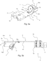
Fig. 5a shows an embodiment, wherein the movable plate is pivotally movable, -
Fig. 5b is a sectional view of embodiment offigure 5a , -
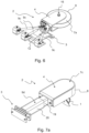
Fig. 6 shows an embodiment, wherein the biasing member comprises three pneumatic cylinders, -
Fig. 7a shows an embodiment, wherein the biasing member comprises a coiled spring and a first housing, and -
Fig. 7b is a sectional view of embodiment offigure 7a . - The system described herein is an sensor system of underground mining vehicles. The underground mining vehicle may be a mine machine or a construction machine e.g. a rock drilling rig, a development drill, a tunneling drilling machine, a surface drilling machine, a bolting or reinforcing vehicle, a rock removal machine, a long hole drill rig, an explosive charging machine, a loader, a transport vehicle, a loading machine, or hauling machine, setting vehicle of gallery arcs or nets, a concrete spraying machine, a crusher, a measuring vehicle, a passenger transport vehicle, or a loading or a hauling machine. The common feature for all these vehicles is that they are designed to operate in harsh conditions underground, wherein the road network is continuously changing. In the following chapters, term vehicle is used but it should be understood as an underground mining vehicle described herein.
- The sensor system, comprising a
sensor 1 and astand 2, is configured to be fastened to the underground mining vehicle at, i.e. in close proximity, a perimeter of the underground mining vehicle so that the system extends over the perimeter of the vehicle, i.e. the outer edge of the system is outside of the perimeter of the vehicle and inner edge of the system is inside the perimeter of the vehicle. Consequently, thesensor 1 may extend over the perimeter of the vehicle and, therefore, provide unrestricted visibility around the vehicle. To protect the sensor from external impacts, the system comprises also aguard member - For example, the system may be fastened to a fender of the vehicle. The fender may be for example front or rear bumber, or it may be a wheel fender.
- The
stand 2 of the sensor system comprises amounting plate 3 for fastening thestand 2 to the vehicle, amovable plate 4 fastened moveably to themounting plate 3, aguard member movable plate 4, and abiasing member movable plate 4 and themounting plate 3. Fastened between the movable plate and the mounting plate should be understood as fastened to the biasing member is fastened to the movable plate and the mounting plate so, that the biasing member is able to act between these components, i.e. the plates may subject forces to the biasing member and vice versa. - The
movable plate 4 has aninner end 5, which is the end towards the center of the vehicle when the system is fastened to the vehicle, and anouter end 6, which is opposite to theinner end 5. Theguard member rim 8, which is pointing outwards of the vehicle, when the system is fastened to the vehicle. Themovable plate 4 may be a thin plate, bended plate, or any part which may be fastened to the mountingplate 3. - The
guard member movable plate 4, i.e. it is in proximity to theouter end 6 so that therim 8 extends over theouter end 6 of themovable plate 4. The guard member may be fastened to the movable plate or it may be integral part of the movable plate. The fastening point of the guard member depends on the size of the guard member. Therefore, the proximity to the outer end means that the fastening point of the guard member is closer to the outer end than the inner end of the movable plate. - The biasing
member movable plate 4 and the mountingplate 3. The biasingmember - The
movable plate 4 has two positions: a resting position, wherein therim 8 of theguard member outer end 6 of themovable plate 4 and thesensor 1 are retracted inside the perimeter of the underground mining vehicle when the system is fastened to the underground mining vehicle. In normal situation, themovable plate 4 is in resting position and therim 8 of the guard member is outside of the perimeter of the vehicle. If theguard member - The following chapters defines different kind of embodiments of the system. Especially, they define different embodiments of the parts or components in the system. The different embodiments may be applied to the system separately or together with other embodiments described herein even if the different optional structures are not described in each embodiment. E.g. different kinds of guard members, biasing members may be applied to any embodiments described herein. Also, any kind of structure of movable plate and/or mounting plate may be applied to any embodiments described herein.
- The
sensor 1 of the system may be for example a vision-based sensor, e.g. camera or other machine vision-based sensor, a scanner, or a radar. The sensor may be located outside of the perimeter of the vehicle, when the system is fastened to the vehicle and the movable plate is in resting position. - The guard member may be a
wheel 7a rotatable around an axis perpendicular to the movement of the movable plate; afixed block 7b, e.g. made of non-elastic or elastic material, such as rubber, which may have a curved rim; or a section of the movable plate forming outer edge of the movable plate. - The
movable plate 4 may move linearly between the resting position and the retracted position on top of the mounting plate, i.e. moving along a straight line. Optionally, the movement may be non-linear, e.g. rotational. - The
movable plate 4 may comprise afirst section 41, which is parallel to the mountingplate 3. All components fastened to themovable plate 4 may be fastened to thefirst section 41. Thefirst section 41 of the movable plate is moveably fastened to the mountingplate 3. Additionally, themovable plate 4 may comprise asecond section 42, that is perpendicular to thefirst section 41. Some of the components of the system may be fastened to thefirst section 41 and some of the components may be fastened to thesecond section 42. For example, thesensor 1 and theguard member first section 41, and the biasingmember second section 42. Optionally, all the components are fastened to thefirst section 41. Additionally, themovable plate 4 may comprise athird section 43, which is parallel to thefirst section 41, and thesecond section 42 is between thefirst section 41 and thethird section 43, i.e. the movable plate is a U-shaped plate. Theguard member first section 41 and thethird section 43. - The mounting
plate 3 is for example an elongated plate having a first surface, on which themovable plate 4 is fastened, a second surface on the opposite side of the plate, long sides, and short sides. The second surface of the mounting plate is the mounting surface which is fastened to the vehicle. However, the mounting plate may be fastened to the vehicle with fastening means that may be fastened to the first surface. The mountingplate 3 may comprise aperpendicular part 31, which may be a bended section or a separate perpendicular part. The biasingmember perpendicular part 31 and themovable plate 4, e.g. thesecond section 42 of the movable plate. Theperpendicular part 31 may comprise ahole 15, which is used for guiding the movement of themovable plate 4. - The system may comprise guiding means 12, 13(a, b,...), 14, 15 for guiding the movement of the
movable plate 4. The guiding means may comprise at least oneopening 12 in the mountingplate 3, fastening means 13a, 13b,... for fastening themovable plate 4 to the mountingplate 3, and/or arod 14 extending from the movable plate through thehole 15 in theperpendicular part 31 of the mountingplate 3. Theopening 12 may be elongated opening or openings arranged in parallel direction to the long sides of the mounting plate. The mountingplate 3 may comprise more than one opening. The fastening means may comprise at least one pin, bolt orscrew 13a, that extends from themovable plate 4 through at least oneopening 12 in the mounting plate3. The pin may comprise threads. Themovable plate 4, e.g. thefirst section 41, may comprise opening and the pin, bolt orscrew 13a is provided through the opening on the movable plate and theopening 12 in the mounting plate. The pin, bolt orscrew 13a may comprise a head and anut 13b, wherein the nut is fastened to the other end of the pin, bolt, or screw, and the movable plate and the mounting plate are arranged between the head and the nut. By tightening thenut 13b to the threads of the pin, bolt or screw, themovable plate 4 and the mountingplate 3 are pressed towards each other. Instead of head, the pin, bolt or screw may comprise another nut in the other end. The fastening means may comprise two or more pins, bolts or screws, and the mounting plate comprises the same number of openings through which the pins, bolts, or screws are fastened. There may be a washer or washers in conjunction with the pin, bolt or screw so that the washer(s) are between the movable plate and the mounting plate. Optionally or additionally, washers may be provided in conjunction with the pin, bolt, or screw so that the washers are between the head of the pin, bolt or screw and the movable plate and/or between the nut and the mounting plate. -
Figure 1 shows an embodiment of thestand 2 of the sensor system. The stand comprises a mountingplate 3 and amovable plate 4 fastened moveably to the mountingplate 3. - The mounting
plate 3 is an elongated sheet, which may be made of metal. The mountingplate 3 comprises a base section comprising the surface to which themovable plate 4 is fastened. The mountingplate 3 comprises aperpendicular part 31 which is perpendicular to the base section. Theperpendicular part 31 is a separate component fastened to the base section. The separateperpendicular part 31 is fastened to the mountingplate 3 by bolts, but optionally, it may be fastened by welding or adhesive or other mechanical means. - The
movable plate 4 is an elongated sheet, which is fastened to the mountingplate 3 moveably, i.e. themovable plate 4 is fastened to the mountingplate 3 but it may move in relation to the mountingplate 3. Themovable plate 4 comprises afirst section 41, that is parallel to the base section of the mountingplate 3, asecond section 42 perpendicular to thefirst section 41, and athird section 43 parallel to thefirst section 41. Thesecond section 42 is between thefirst section 41 andthird section 43. - The
stand 2 comprises a guard member fastened to the movable plate. The guard member in embodiment offigure 1 is awheel 7a, which is rotatable about anaxle 16 perpendicular to themovable plate 4. Thewheel 7a is fastened between thefirst section 41 and thethird section 43 of the movable plate by theaxle 16. Thewheel 7a comprises arim 8, which is defined by perimeter of thewheel 7a. - The
stand 2 comprises a biasing member between themovable plate 4 and the mountingplate 3. Infigure 1 , the biasing member is acoiled spring 9a arranged between theperpendicular part 31 of the mounting plate and thesecond section 42 of the movable plate, whereby thecoiled spring 9a is biasing themovable plate 4 to the resting position. If therim 8 of thewheel 7a is subjected to an external force that exceeds the biasing force of thecoiled spring 9a, themovable plate 4 retracts towards the retracted position, i.e. towards theperpendicular part 31 of the mounting plate. - The
stand 2 comprises guiding means for guiding the movement of themovable plate 4. The guiding means infigure 1 comprises twoelongated openings 12 in base section of the mountingplate 3. Themovable plate 4 is fastened to theopenings 12 in the mounting plate with fastening means so that themovable plate 4 is movable along the elongated openings. The fastening means comprisesbolts 13a and nuts 13b (seen infigure 2 ). The bolts are fastened through thefirst section 41 of the movable plate and through theelongated openings 12 in the mounting plate. The nuts 13b are fastened to the bolts so that the movable plate and mounting plate are squeezed towards each other by the screw head and nut. Theelongated openings 12 define a path which the movable plate may move in relation to the mounting plate. Infigure 1 , the elongated openings are linear, and themovable plate 4 moves linearly along theseopenings 12 between the resting position and the retracted position. The guiding means comprises also anelongated rod 14, which is extending from thesecond section 42 of themovable plate 4. Theperpendicular part 31 comprises ahole 15, and therod 14 is extending through thehole 15. Thecoiled spring 9a is arranged coaxially around theelongated rod 14 so that the elongated rod runs through thecoiled spring 9a, whereby theelongated rod 14 supports thecoiled spring 9a. -
Figure 2 shows a side view of thestand 2 shown infigure 1 , wherein asensor 1 is fastened to themovable plate 4. Thesensor 1 is located between therim 8 of thewheel 7a and theinner end 5 of themovable plate 4. By such location, therim 8 of the guard member, i.e.wheel 7a, protects thesensor 1 from external forces, such as impacts of obstacles. Thesensor 1 is fastened to thefirst section 41 of themovable plate 4 by a fastening part, which infigure 2 is abended sheet 11. The bended sheet may be for example metal sheet. -
Figure 3 shows the system offigure 2 but themovable plate 4 is in retracted position, i.e. the biasing member, i.e. thecoiled spring 9a, is compressed and themovable plate 4 is retracted towards theperpendicular part 31 of the mountingplate 3. -
Figure 4 shows an embodiment, wherein the biasing member comprises apneumatic cylinder 9b, which is fastened between the mountingplate 3 and themovable plate 4. The mountingplate 3 comprises aperpendicular section 31 and thepneumatic cylinder 9b is fastened to theperpendicular section 31. The guard member is awheel 7a, which is fastened to themovable plate 4 viaperpendicular axle 16 so that thewheel 7a is rotatable about theperpendicular axle 16. Instead ofpneumatic cylinder 9a, the biasing member may comprise hydraulic cylinder. -
Figure 5a shows an embodiment, wherein themovable plate 4 is fastened to the mountingplate 3 with anaxle 18 so that themovable plate 4 may rotate about theaxle 18.Figure 5b is a sectional side view of the embodiment. Themovable plate 4 comprises afirst section 41 and aguard section 7b, which is at theouter end 6 of themovable plate 4, comprising a parallel section 7b1, which is parallel to thefirst section 41, and a perpendicular section 7b2 being perpendicular to thefirst section 41 and parallel section 7b1. Theguard section 7b is the guard member in this embodiment. The perpendicular section 7b2 of the guard section may be bended from the parallel section 7b1, or it may be fastened to the parallel section e.g. by welding. The perpendicular section 7b1 forms therim 8 of the guard member. The parallel section 7b1 may be extension to the first section, i.e. uniform structure, or it may be fastened to the first section by fastening means, e.g. screws or bolts. A bearing orbearings 19 may be provided between theaxle 18 and themovable plate 4 and/or between theaxle 18 and the mountingplate 3. The biasing member may be for example a spiral spring (not shown in figure), which is fastened between the mountingplate 3 and themovable plate 4 to bias themovable plate 4 to the resting position. When the guard member, i.e. the guard section 7b2, is subjected to an external force, themovable plate 4 rotates about theaxle 18 to the retracted position. Infigure 5a and 5b , the movable plate is in resting position. -
Figure 6 shows an embodiment, wherein the biasing member comprises threepneumatic cylinders 9c between the movable plate and the mounting plate. Thepneumatic cylinders 9c may be in parallel plane, or in separate planes which are essentially parallel to each other. The fastening points of the cylinders in mounting plate and fastening points in the movable plate are located at a distance to each other so that they form a triangle shape. The distance between adjacent fastening points in mounting plate is greater than the distance between adjacent fastening points in movable plate. Thus, the three cylinders are fastened to the mounting plate so that they allow both rotational and linear movement of the movable plate. The guard member in these figures is awheel 7a but it may be any kind of guard member described herein. Instead ofpneumatic cylinders 9c, the biasing member may comprise hydraulic cylinders. -
Figure 7a shows an embodiment, wherein the biasing member comprises acoiled spring 9d and afirst housing 19, and the mountingplate 3 comprises asecond housing 20 and aperpendicular part 31. Theperpendicular part 31 is an annular ring extending radially towards the center axis of thesecond housing 20. Theperpendicular part 31 may be separate part fastened to thesecond housing 20, e.g. by welding, or it may be bended section of thesecond housing 20.Figure 7b shows a cross section of the same embodiment. Thefirst housing 19 andsecond housing 20 are arranged coaxially so that the first housing is inside the second housing. Thefirst housing 19 is fastened to themovable plate 4 and configured to move in axial direction so that themovable plate 4 may move between resting position and retracted position. Themovable plate 4 is made of sheet, e.g. made of metal, which is bended to form enclosed capsule. Thecoiled spring 9d is arranged coaxially inside thefirst housing 19, and is arranged between themovable plate 4 and theperpendicular part 31 of the second housing, i.e. mountingplate 3. Thecoiled spring 9d may be fixed to themovable plate 4 and/orperpendicular part 31, or it may be arranged freely, i.e. not fixed to themovable plate 4 or theperpendicular part 31. Theguard member 7c at the outer end of the movable plate is an integral part of the enclosed capsule. The stand comprises anelongated rod 14, which is arranged coaxially inside thecoiled spring 9d, and therod 14 is extending from themovable plate 4 through an opening in theperpendicular part 31. The rim of theguard member 7c is curved (in horizontal plane), but optionally, it may have different shapes. - Although the invention has been the described in conjunction with a certain type of system, it should be understood that the invention is not limited to any certain type of system. While the present inventions have been described in connection with a number of exemplary embodiments, and implementations, the present inventions are not so limited, but rather cover various modifications, and equivalent arrangements, which fall within the purview of prospective claims.
Claims (15)
- A sensor system of underground mining vehicles, which system is arranged to be fastened at a perimeter of an underground mining vehicle, comprising a sensor (1) and a stand (2), wherein the stand comprises- a mounting plate (3) for fastening the stand (2) to the underground mining vehicle,- a movable plate (4), having an inner end (5) and an outer end (6), fastened moveably to the mounting plate (3),- a guard member (7a, 7b,...) comprising a rim (8), which guard member (7a, 7b,...) is provided at the outer end (6) so that the rim (8) extends over the outer end (6) of the movable plate (4), and- a biasing member (9a, 9b,...) fastened between the movable plate (4) and the mounting plate (3) ;whereinthe sensor (1) is fastened to the movable plate (4) so that the sensor (1) is between the rim (8) of the guard member (7a, 7b,...) and the inner end (5) of the movable plate (4),the movable plate (4) has two positions:- a resting position, wherein the rim of the guard member (7a, 7b,...) is extending outside of the underground vehicle perimeter when the system is fastened to the underground mining vehicle, and- a retracted position, wherein the outer end (6) and the sensor (1) are retracted inside the perimeter of the underground mining vehicle when the system is fastened to the underground mining vehicle,andthe biasing member (9a, 9b,...) is biasing the movable plate (4) to the resting position.
- The sensor system of an underground mining vehicle according to claim 1, wherein the sensor (1) is outside the perimeter of the underground mining vehicle when the movable plate (4) is in the resting position.
- The sensor system of an underground mining vehicle according to claim 1 or 2, wherein the biasing member (9a, 9b,...) is a mechanical spring.
- The sensor system of an underground mining vehicle according to any one of claims 1 to 3, wherein the biasing member (9a, 9b,...) is made of rubber.
- The sensor system of an underground mining vehicle according to claim 1 or 2, wherein the biasing member (9a, 9b,...) comprises a hydraulic cylinder or a pneumatic cylinder.
- The sensor system of an underground mining vehicle according to any one of claims 1 to 5, wherein the guard member (7a, 7b,...) is a wheel fastened to the movable plate (4) with an axle (10) perpendicular to the movable plate (4).
- The sensor system of an underground mining vehicle according to any one of claims 1 to 6, wherein the movable plate (4) is arranged to move linearly between the resting position and the retracted position on top of the mounting plate (3).
- The sensor system of an underground mining vehicle according to any one of claims 1 to 7, wherein the movable plate (4) comprises at least two sections, a first section (41) being parallel to the mounting plate (3), and a second section (42) being perpendicular to the first section (41).
- The sensor system of an underground mining vehicle according to claim 8, wherein the movable plate (4) comprises a third section (43), which is parallel to the first section (41), and the second section (42) is arranged between the first section (41) and the third section (43).
- The sensor system of an underground mining vehicle according to claim 8 or 9, wherein the mounting plate (3) comprises a perpendicular part (31), and the biasing member (9a, 9b,...) is arranged between the perpendicular part (31) and the second section (42) of the movable plate (4).
- The sensor system of an underground mining vehicle according to any one of claims 1 to 10, wherein the stand (2) comprises guiding means for guiding the movement of the movable plate (4) between the resting position and the retracted position.
- The sensor system of an underground mining vehicle according to claim 11, wherein the guiding means comprises at least one elongated opening (12) in the mounting plate (3), and fastening means (13a, 13b,...) for fastening the movable plate (4) to the mounting plate (3), wherein the fastening means are configured to extend from the movable plate (4) through the at least one elongated opening (12).
- The sensor system of an underground mining vehicle according to claim 10 and 11 or 12, wherein the guiding means (11) comprises an elongated rod (14) extending from the second section (42) of the movable plate (4) and a hole (15) in the perpendicular part (31) of the mounting plate (3), wherein the elongated rod (14) extends from the second section (42) through the hole (15) in the perpendicular part (31).
- The sensor system of an underground mining vehicle according to any one of claims 1 to 13, wherein the movable plate (4), together with the guard member (7a, 7b,...) and the sensor (1) fastened to the movable plate, is arranged to move towards the retracted position when the rim (8) is subjected to an external force exceeding the biasing force of the biasing member (9a, 9b,...).
- An underground mining vehicle comprising a sensor system according to any one of claims 1 to 14.
Priority Applications (7)
| Application Number | Priority Date | Filing Date | Title |
|---|---|---|---|
| EP22156249.9A EP4227488B1 (en) | 2022-02-11 | 2022-02-11 | Sensor system of underground mining vehicles and underground mining vehicle comprising sensor system |
| PL22156249.9T PL4227488T3 (en) | 2022-02-11 | 2022-02-11 | Sensor system of underground mining vehicles and underground mining vehicle comprising sensor system |
| US18/836,453 US12618327B2 (en) | 2022-02-11 | 2023-02-03 | Sensor system of underground mining vehicles and underground mining vehicle comprising sensor system |
| CA3247666A CA3247666A1 (en) | 2022-02-11 | 2023-02-03 | Sensor system of underground mining vehicles and underground mining vehicle comprising sensor system |
| AU2023218884A AU2023218884A1 (en) | 2022-02-11 | 2023-02-03 | Sensor system of underground mining vehicles and underground mining vehicle comprising sensor system |
| PCT/EP2023/052621 WO2023152030A1 (en) | 2022-02-11 | 2023-02-03 | Sensor system of underground mining vehicles and underground mining vehicle comprising sensor system |
| CN202380020048.6A CN118742706A (en) | 2022-02-11 | 2023-02-03 | Sensor system for an underground mining vehicle and underground mining vehicle comprising the sensor system |
Applications Claiming Priority (1)
| Application Number | Priority Date | Filing Date | Title |
|---|---|---|---|
| EP22156249.9A EP4227488B1 (en) | 2022-02-11 | 2022-02-11 | Sensor system of underground mining vehicles and underground mining vehicle comprising sensor system |
Publications (3)
| Publication Number | Publication Date |
|---|---|
| EP4227488A1 true EP4227488A1 (en) | 2023-08-16 |
| EP4227488C0 EP4227488C0 (en) | 2024-06-19 |
| EP4227488B1 EP4227488B1 (en) | 2024-06-19 |
Family
ID=80446675
Family Applications (1)
| Application Number | Title | Priority Date | Filing Date |
|---|---|---|---|
| EP22156249.9A Active EP4227488B1 (en) | 2022-02-11 | 2022-02-11 | Sensor system of underground mining vehicles and underground mining vehicle comprising sensor system |
Country Status (7)
| Country | Link |
|---|---|
| US (1) | US12618327B2 (en) |
| EP (1) | EP4227488B1 (en) |
| CN (1) | CN118742706A (en) |
| AU (1) | AU2023218884A1 (en) |
| CA (1) | CA3247666A1 (en) |
| PL (1) | PL4227488T3 (en) |
| WO (1) | WO2023152030A1 (en) |
Citations (4)
| Publication number | Priority date | Publication date | Assignee | Title |
|---|---|---|---|---|
| US3861488A (en) * | 1971-03-08 | 1975-01-21 | Mitsubishi Electric Corp | Collision speed sensor |
| US4189183A (en) * | 1977-07-23 | 1980-02-19 | Gebr. Eickhoff, Maschinenfabrik Und Eisengiesserei M.B.H. | Mining machine with cutter drums and sensing apparatus |
| CN201730617U (en) * | 2010-08-20 | 2011-02-02 | 三一重型装备有限公司 | Entry driving machine |
| GB2489590A (en) * | 2011-04-01 | 2012-10-03 | Joy Mm Delaware Inc | Proximity sensing and control system for a mining machine |
Family Cites Families (8)
| Publication number | Priority date | Publication date | Assignee | Title |
|---|---|---|---|---|
| US6253557B1 (en) * | 1998-10-05 | 2001-07-03 | The Coca-Cola Company | Ice bank detector |
| US6553925B1 (en) * | 1999-04-23 | 2003-04-29 | Straw Track Mfg., Inc. | No-till stubble row seeder guidance system and method |
| US6370952B1 (en) * | 1999-06-01 | 2002-04-16 | Aaron Little | Vehicle oil level monitoring system |
| US12250898B2 (en) * | 2016-07-22 | 2025-03-18 | Precision Planting Llc | Agricultural trench depth sensing systems, methods, and apparatus |
| WO2019099748A1 (en) * | 2017-11-15 | 2019-05-23 | Precision Planting Llc | Seed trench closing sensors |
| US11711994B2 (en) * | 2019-03-29 | 2023-08-01 | Cnh Industrial Canada, Ltd. | System and method for monitoring the condition of a lateral swath of a seedbed with a seedbed floor detection assembly |
| US11480677B2 (en) * | 2019-05-23 | 2022-10-25 | GM Global Technology Operations LLC | Tool for applying a protective film to a lens of a LIDAR sensor |
| US11802756B2 (en) * | 2020-08-18 | 2023-10-31 | Steven R. Weeres | Ice thickness transducer |
-
2022
- 2022-02-11 EP EP22156249.9A patent/EP4227488B1/en active Active
- 2022-02-11 PL PL22156249.9T patent/PL4227488T3/en unknown
-
2023
- 2023-02-03 US US18/836,453 patent/US12618327B2/en active Active
- 2023-02-03 CA CA3247666A patent/CA3247666A1/en active Pending
- 2023-02-03 AU AU2023218884A patent/AU2023218884A1/en active Pending
- 2023-02-03 WO PCT/EP2023/052621 patent/WO2023152030A1/en not_active Ceased
- 2023-02-03 CN CN202380020048.6A patent/CN118742706A/en active Pending
Patent Citations (4)
| Publication number | Priority date | Publication date | Assignee | Title |
|---|---|---|---|---|
| US3861488A (en) * | 1971-03-08 | 1975-01-21 | Mitsubishi Electric Corp | Collision speed sensor |
| US4189183A (en) * | 1977-07-23 | 1980-02-19 | Gebr. Eickhoff, Maschinenfabrik Und Eisengiesserei M.B.H. | Mining machine with cutter drums and sensing apparatus |
| CN201730617U (en) * | 2010-08-20 | 2011-02-02 | 三一重型装备有限公司 | Entry driving machine |
| GB2489590A (en) * | 2011-04-01 | 2012-10-03 | Joy Mm Delaware Inc | Proximity sensing and control system for a mining machine |
Non-Patent Citations (1)
| Title |
|---|
| HESSELBACH J ET AL: "AUTOMATISIERTE POSITIONIERUNG EINES UNTER-TAGE-BOHRWAGENS. ÖAUTOMATISED POSITIONING OF AN UNDERGROUND DRILLING VESSEL", AUTOMATISIERUNGSTECHNISCHE PRAXIS - ATP, OLDENBOURG INDUSTRIEVERLAG, MUNCHEN, DE, vol. 37, no. 6, 1 June 1995 (1995-06-01), pages 20, XP000511027, ISSN: 0178-2320 * |
Also Published As
| Publication number | Publication date |
|---|---|
| AU2023218884A1 (en) | 2024-08-15 |
| EP4227488C0 (en) | 2024-06-19 |
| EP4227488B1 (en) | 2024-06-19 |
| PL4227488T3 (en) | 2024-09-16 |
| US12618327B2 (en) | 2026-05-05 |
| CN118742706A (en) | 2024-10-01 |
| US20250129719A1 (en) | 2025-04-24 |
| CA3247666A1 (en) | 2023-08-17 |
| WO2023152030A1 (en) | 2023-08-17 |
Similar Documents
| Publication | Publication Date | Title |
|---|---|---|
| US10093361B2 (en) | Adjustable vehicular fender extension | |
| US20150175110A1 (en) | Offset Impact Countermeasures | |
| EP3002824B1 (en) | Breakaway mast | |
| US9045881B1 (en) | Deployable safety apparatus | |
| EP4227488B1 (en) | Sensor system of underground mining vehicles and underground mining vehicle comprising sensor system | |
| US20200282919A1 (en) | Dump truck | |
| WO2017066076A1 (en) | Telescoping vehicle safety guard | |
| CA3151302A1 (en) | Roadway debris clearing system | |
| EP1029985A2 (en) | Impact-resistant and energy-absorbing safety post | |
| US20120205961A1 (en) | Transporter vehicle | |
| JPH06501224A (en) | Reversing protection cab for large off-road machines | |
| JP2011241643A (en) | Camera mounting device in working machine | |
| US4143898A (en) | Bumper for track suspension of a tracklaying vehicle | |
| EP3272625A1 (en) | Hydraulic cylinder for utility vehicle | |
| US7572044B2 (en) | Emergency light bar mounting assembly rotatable between a horizontal deployed position and a vertical stowed position | |
| US6345858B1 (en) | Wide body for an off the highway truck | |
| AU2020292108B2 (en) | Torque element and system for absorbing shear forces in a bolt con¬ nection for connecting a bucket element in a loading machine bucket | |
| US9051715B2 (en) | Crowd machinery guard for mining shovel | |
| JP6132763B2 (en) | Hydraulic hammer device and hydraulic hammer | |
| KR200361385Y1 (en) | A Device For Restricting The Passing Height Of Vehicles | |
| CN216475255U (en) | Cylinder guards and construction machinery including the same | |
| KR200326787Y1 (en) | limit apparatus for vehicle passing height | |
| US11066015B2 (en) | Adjustable mirror assembly for a work machine | |
| JPH08326024A (en) | Boom or support arm retractor for work vehicle | |
| WO2025174591A1 (en) | Rock guard for gnss signal avoidance |
Legal Events
| Date | Code | Title | Description |
|---|---|---|---|
| PUAI | Public reference made under article 153(3) epc to a published international application that has entered the european phase |
Free format text: ORIGINAL CODE: 0009012 |
|
| STAA | Information on the status of an ep patent application or granted ep patent |
Free format text: STATUS: THE APPLICATION HAS BEEN PUBLISHED |
|
| AK | Designated contracting states |
Kind code of ref document: A1 Designated state(s): AL AT BE BG CH CY CZ DE DK EE ES FI FR GB GR HR HU IE IS IT LI LT LU LV MC MK MT NL NO PL PT RO RS SE SI SK SM TR |
|
| STAA | Information on the status of an ep patent application or granted ep patent |
Free format text: STATUS: REQUEST FOR EXAMINATION WAS MADE |
|
| 17P | Request for examination filed |
Effective date: 20240206 |
|
| RBV | Designated contracting states (corrected) |
Designated state(s): AL AT BE BG CH CY CZ DE DK EE ES FI FR GB GR HR HU IE IS IT LI LT LU LV MC MK MT NL NO PL PT RO RS SE SI SK SM TR |
|
| GRAP | Despatch of communication of intention to grant a patent |
Free format text: ORIGINAL CODE: EPIDOSNIGR1 |
|
| STAA | Information on the status of an ep patent application or granted ep patent |
Free format text: STATUS: GRANT OF PATENT IS INTENDED |
|
| RIC1 | Information provided on ipc code assigned before grant |
Ipc: A47F 1/12 20060101ALI20240312BHEP Ipc: B60R 21/0136 20060101ALI20240312BHEP Ipc: E21C 35/10 20060101ALI20240312BHEP Ipc: E21C 35/04 20060101ALI20240312BHEP Ipc: E21D 9/00 20060101ALI20240312BHEP Ipc: E21B 47/013 20120101AFI20240312BHEP |
|
| INTG | Intention to grant announced |
Effective date: 20240408 |
|
| GRAS | Grant fee paid |
Free format text: ORIGINAL CODE: EPIDOSNIGR3 |
|
| GRAA | (expected) grant |
Free format text: ORIGINAL CODE: 0009210 |
|
| STAA | Information on the status of an ep patent application or granted ep patent |
Free format text: STATUS: THE PATENT HAS BEEN GRANTED |
|
| AK | Designated contracting states |
Kind code of ref document: B1 Designated state(s): AL AT BE BG CH CY CZ DE DK EE ES FI FR GB GR HR HU IE IS IT LI LT LU LV MC MK MT NL NO PL PT RO RS SE SI SK SM TR |
|
| REG | Reference to a national code |
Ref country code: GB Ref legal event code: FG4D |
|
| REG | Reference to a national code |
Ref country code: CH Ref legal event code: EP |
|
| REG | Reference to a national code |
Ref country code: DE Ref legal event code: R096 Ref document number: 602022003968 Country of ref document: DE |
|
| U01 | Request for unitary effect filed |
Effective date: 20240626 |
|
| U07 | Unitary effect registered |
Designated state(s): AT BE BG DE DK EE FI FR IT LT LU LV MT NL PT SE SI Effective date: 20240802 |
|
| PG25 | Lapsed in a contracting state [announced via postgrant information from national office to epo] |
Ref country code: HR Free format text: LAPSE BECAUSE OF FAILURE TO SUBMIT A TRANSLATION OF THE DESCRIPTION OR TO PAY THE FEE WITHIN THE PRESCRIBED TIME-LIMIT Effective date: 20240619 |
|
| PG25 | Lapsed in a contracting state [announced via postgrant information from national office to epo] |
Ref country code: GR Free format text: LAPSE BECAUSE OF FAILURE TO SUBMIT A TRANSLATION OF THE DESCRIPTION OR TO PAY THE FEE WITHIN THE PRESCRIBED TIME-LIMIT Effective date: 20240920 |
|
| PG25 | Lapsed in a contracting state [announced via postgrant information from national office to epo] |
Ref country code: NO Free format text: LAPSE BECAUSE OF FAILURE TO SUBMIT A TRANSLATION OF THE DESCRIPTION OR TO PAY THE FEE WITHIN THE PRESCRIBED TIME-LIMIT Effective date: 20240919 Ref country code: HR Free format text: LAPSE BECAUSE OF FAILURE TO SUBMIT A TRANSLATION OF THE DESCRIPTION OR TO PAY THE FEE WITHIN THE PRESCRIBED TIME-LIMIT Effective date: 20240619 Ref country code: GR Free format text: LAPSE BECAUSE OF FAILURE TO SUBMIT A TRANSLATION OF THE DESCRIPTION OR TO PAY THE FEE WITHIN THE PRESCRIBED TIME-LIMIT Effective date: 20240920 Ref country code: RS Free format text: LAPSE BECAUSE OF FAILURE TO SUBMIT A TRANSLATION OF THE DESCRIPTION OR TO PAY THE FEE WITHIN THE PRESCRIBED TIME-LIMIT Effective date: 20240919 |
|
| PG25 | Lapsed in a contracting state [announced via postgrant information from national office to epo] |
Ref country code: IS Free format text: LAPSE BECAUSE OF FAILURE TO SUBMIT A TRANSLATION OF THE DESCRIPTION OR TO PAY THE FEE WITHIN THE PRESCRIBED TIME-LIMIT Effective date: 20241019 |
|
| PG25 | Lapsed in a contracting state [announced via postgrant information from national office to epo] |
Ref country code: RO Free format text: LAPSE BECAUSE OF FAILURE TO SUBMIT A TRANSLATION OF THE DESCRIPTION OR TO PAY THE FEE WITHIN THE PRESCRIBED TIME-LIMIT Effective date: 20240619 Ref country code: SK Free format text: LAPSE BECAUSE OF FAILURE TO SUBMIT A TRANSLATION OF THE DESCRIPTION OR TO PAY THE FEE WITHIN THE PRESCRIBED TIME-LIMIT Effective date: 20240619 |
|
| PG25 | Lapsed in a contracting state [announced via postgrant information from national office to epo] |
Ref country code: ES Free format text: LAPSE BECAUSE OF FAILURE TO SUBMIT A TRANSLATION OF THE DESCRIPTION OR TO PAY THE FEE WITHIN THE PRESCRIBED TIME-LIMIT Effective date: 20240619 Ref country code: SM Free format text: LAPSE BECAUSE OF FAILURE TO SUBMIT A TRANSLATION OF THE DESCRIPTION OR TO PAY THE FEE WITHIN THE PRESCRIBED TIME-LIMIT Effective date: 20240619 |
|
| PG25 | Lapsed in a contracting state [announced via postgrant information from national office to epo] |
Ref country code: SM Free format text: LAPSE BECAUSE OF FAILURE TO SUBMIT A TRANSLATION OF THE DESCRIPTION OR TO PAY THE FEE WITHIN THE PRESCRIBED TIME-LIMIT Effective date: 20240619 Ref country code: SK Free format text: LAPSE BECAUSE OF FAILURE TO SUBMIT A TRANSLATION OF THE DESCRIPTION OR TO PAY THE FEE WITHIN THE PRESCRIBED TIME-LIMIT Effective date: 20240619 Ref country code: RO Free format text: LAPSE BECAUSE OF FAILURE TO SUBMIT A TRANSLATION OF THE DESCRIPTION OR TO PAY THE FEE WITHIN THE PRESCRIBED TIME-LIMIT Effective date: 20240619 Ref country code: IS Free format text: LAPSE BECAUSE OF FAILURE TO SUBMIT A TRANSLATION OF THE DESCRIPTION OR TO PAY THE FEE WITHIN THE PRESCRIBED TIME-LIMIT Effective date: 20241019 Ref country code: ES Free format text: LAPSE BECAUSE OF FAILURE TO SUBMIT A TRANSLATION OF THE DESCRIPTION OR TO PAY THE FEE WITHIN THE PRESCRIBED TIME-LIMIT Effective date: 20240619 |
|
| U20 | Renewal fee for the european patent with unitary effect paid |
Year of fee payment: 4 Effective date: 20250228 |
|
| PLBE | No opposition filed within time limit |
Free format text: ORIGINAL CODE: 0009261 |
|
| STAA | Information on the status of an ep patent application or granted ep patent |
Free format text: STATUS: NO OPPOSITION FILED WITHIN TIME LIMIT |
|
| 26N | No opposition filed |
Effective date: 20250320 |
|
| PG25 | Lapsed in a contracting state [announced via postgrant information from national office to epo] |
Ref country code: MC Free format text: LAPSE BECAUSE OF FAILURE TO SUBMIT A TRANSLATION OF THE DESCRIPTION OR TO PAY THE FEE WITHIN THE PRESCRIBED TIME-LIMIT Effective date: 20240619 |
|
| REG | Reference to a national code |
Ref country code: CH Ref legal event code: PL |
|
| PG25 | Lapsed in a contracting state [announced via postgrant information from national office to epo] |
Ref country code: CH Free format text: LAPSE BECAUSE OF NON-PAYMENT OF DUE FEES Effective date: 20250228 |
|
| PG25 | Lapsed in a contracting state [announced via postgrant information from national office to epo] |
Ref country code: IE Free format text: LAPSE BECAUSE OF NON-PAYMENT OF DUE FEES Effective date: 20250211 |
|
| PGFP | Annual fee paid to national office [announced via postgrant information from national office to epo] |
Ref country code: PL Payment date: 20251230 Year of fee payment: 5 |
|
| U20 | Renewal fee for the european patent with unitary effect paid |
Year of fee payment: 5 Effective date: 20260302 |
|
| PGFP | Annual fee paid to national office [announced via postgrant information from national office to epo] |
Ref country code: CZ Payment date: 20260128 Year of fee payment: 5 |
|
| PG25 | Lapsed in a contracting state [announced via postgrant information from national office to epo] |
Ref country code: CY Free format text: LAPSE BECAUSE OF FAILURE TO SUBMIT A TRANSLATION OF THE DESCRIPTION OR TO PAY THE FEE WITHIN THE PRESCRIBED TIME-LIMIT Effective date: 20240619 |
|
| PG25 | Lapsed in a contracting state [announced via postgrant information from national office to epo] |
Ref country code: TR Free format text: LAPSE BECAUSE OF FAILURE TO SUBMIT A TRANSLATION OF THE DESCRIPTION OR TO PAY THE FEE WITHIN THE PRESCRIBED TIME-LIMIT Effective date: 20240619 |