EP4227484B1 - Shoe care apparatus - Google Patents
Shoe care apparatus Download PDFInfo
- Publication number
- EP4227484B1 EP4227484B1 EP22798994.4A EP22798994A EP4227484B1 EP 4227484 B1 EP4227484 B1 EP 4227484B1 EP 22798994 A EP22798994 A EP 22798994A EP 4227484 B1 EP4227484 B1 EP 4227484B1
- Authority
- EP
- European Patent Office
- Prior art keywords
- door
- rivet
- shoe
- coupled
- care apparatus
- Prior art date
- Legal status (The legal status is an assumption and is not a legal conclusion. Google has not performed a legal analysis and makes no representation as to the accuracy of the status listed.)
- Active
Links
Images




Classifications
-
- A—HUMAN NECESSITIES
- A47—FURNITURE; DOMESTIC ARTICLES OR APPLIANCES; COFFEE MILLS; SPICE MILLS; SUCTION CLEANERS IN GENERAL
- A47L—DOMESTIC WASHING OR CLEANING; SUCTION CLEANERS IN GENERAL
- A47L23/00—Cleaning footwear
- A47L23/20—Devices or implements for drying footwear, also with heating arrangements
- A47L23/205—Devices or implements for drying footwear, also with heating arrangements with heating arrangements
-
- A—HUMAN NECESSITIES
- A47—FURNITURE; DOMESTIC ARTICLES OR APPLIANCES; COFFEE MILLS; SPICE MILLS; SUCTION CLEANERS IN GENERAL
- A47L—DOMESTIC WASHING OR CLEANING; SUCTION CLEANERS IN GENERAL
- A47L23/00—Cleaning footwear
- A47L23/20—Devices or implements for drying footwear, also with heating arrangements
-
- A—HUMAN NECESSITIES
- A43—FOOTWEAR
- A43D—MACHINES, TOOLS, EQUIPMENT OR METHODS FOR MANUFACTURING OR REPAIRING FOOTWEAR
- A43D3/00—Lasts
- A43D3/14—Stretching or spreading lasts; Boot-trees; Fillers; Devices for maintaining the shape of the shoe
- A43D3/1408—Devices for heating or drying shoes
-
- A—HUMAN NECESSITIES
- A43—FOOTWEAR
- A43D—MACHINES, TOOLS, EQUIPMENT OR METHODS FOR MANUFACTURING OR REPAIRING FOOTWEAR
- A43D3/00—Lasts
- A43D3/14—Stretching or spreading lasts; Boot-trees; Fillers; Devices for maintaining the shape of the shoe
- A43D3/1433—Shoe-trees
- A43D3/1491—Shoe-trees with means for sweaty feet, e.g. with disinfecting or deodorant means
-
- A—HUMAN NECESSITIES
- A47—FURNITURE; DOMESTIC ARTICLES OR APPLIANCES; COFFEE MILLS; SPICE MILLS; SUCTION CLEANERS IN GENERAL
- A47B—TABLES; DESKS; OFFICE FURNITURE; CABINETS; DRAWERS; GENERAL DETAILS OF FURNITURE
- A47B61/00—Wardrobes
- A47B61/04—Wardrobes for shoes, hats, umbrellas, or the like
-
- A—HUMAN NECESSITIES
- A47—FURNITURE; DOMESTIC ARTICLES OR APPLIANCES; COFFEE MILLS; SPICE MILLS; SUCTION CLEANERS IN GENERAL
- A47L—DOMESTIC WASHING OR CLEANING; SUCTION CLEANERS IN GENERAL
- A47L23/00—Cleaning footwear
- A47L23/18—Devices for holding footwear during cleaning or shining; Holding devices with stretching effect
-
- E—FIXED CONSTRUCTIONS
- E06—DOORS, WINDOWS, SHUTTERS, OR ROLLER BLINDS IN GENERAL; LADDERS
- E06B—FIXED OR MOVABLE CLOSURES FOR OPENINGS IN BUILDINGS, VEHICLES, FENCES OR LIKE ENCLOSURES IN GENERAL, e.g. DOORS, WINDOWS, BLINDS, GATES
- E06B3/00—Window sashes, door leaves, or like elements for closing wall or like openings; Layout of fixed or moving closures, e.g. windows in wall or like openings; Features of rigidly-mounted outer frames relating to the mounting of wing frames
- E06B3/70—Door leaves
-
- E—FIXED CONSTRUCTIONS
- E06—DOORS, WINDOWS, SHUTTERS, OR ROLLER BLINDS IN GENERAL; LADDERS
- E06B—FIXED OR MOVABLE CLOSURES FOR OPENINGS IN BUILDINGS, VEHICLES, FENCES OR LIKE ENCLOSURES IN GENERAL, e.g. DOORS, WINDOWS, BLINDS, GATES
- E06B3/00—Window sashes, door leaves, or like elements for closing wall or like openings; Layout of fixed or moving closures, e.g. windows in wall or like openings; Features of rigidly-mounted outer frames relating to the mounting of wing frames
- E06B3/70—Door leaves
- E06B3/82—Flush doors, i.e. with completely flat surface
Definitions
- the invention relates to a shoe care apparatus, and more particularly, to a shoe care apparatus with an improved door structure.
- a shoe care apparatus is an apparatus for maintaining shoes by drying the shoes, keeping the shoes clean, or deodorizing the shoes.
- the shoe care apparatus includes a cabinet, a care room provided inside the cabinet for accommodating shoes, and a door coupled with the cabinet to open and close the care room.
- the door should have sufficient stiffness such that it is not deformed during a use process. Although there are various methods for reinforcing the stiffness of the door, a method for simplifying an assembly process while reducing material cost is described herein.
- CN 105 831 995 A describes a shoe cabinet comprising a cabinet body and a cabinet door.
- the cabinet body has a rectangular cuboid shape, and the cabinet door has a flat plate shape.
- the cabinet body has an open end face, and the cabinet door is disposed on the open surface of the cabinet body.
- a magnetic closure strip is arranged between the cabinet body and the cabinet door. When the locker door is closed, the entire interior of the shoe cabinet is closed.
- JP 2021 040909 A describes a shoe dryer with a housing that forms an outer shell.
- the housing comprises a door provided on the front side and opened/closed for taking shoes in and out, a left side panel, a right side panel, and a rear panel. Furthermore, the housing includes a top plate and a bottom plate.
- It is still another aspect of the invention to provide a shoe care apparatus including a door implemented by coupling a rear body provided as an injection mold with a cover plate provided as a metal material by using a rivet.
- a shoe care apparatus includes: a main body; a care room provided inside the main body and accommodating shoes; and a door opening and closing the care room, wherein the door includes: a front panel forming a front surface of the door, and including a side trim provided on a rear surface of the front panel or a magnet provided on the rear surface of the front panel; a rear body forming a rear surface of the door; and a reinforcement plate positioned between the front panel and the rear body, and detachably coupled with the front panel, and the reinforcement plate includes: a recess portion accommodating at least one portion of the side trim; and a magnet coupling portion coupled with the magnet by a magnetic force of the magnet, and arranged in parallel to the recess portion.
- the door may include: a first door cover including the side trim and a first front panel including a first material; or a second door cover including the magnet and a second front panel including a second material that is different from the first material.
- the door may include a bracket positioned between the reinforcement plate and the rear body, and coupled with the rear body and the reinforcement plate to couple the reinforcement plate with the rear body.
- the reinforcement plate may be coupled with the rear body by a first coupling member.
- the bracket may be coupled with the rear body by a second coupling member which is different from the first coupling member.
- At least one of the first coupling member and the second coupling member may include a rivet.
- the rear body may further include a rivet coupling portion with which the rivet is coupled, wherein the rivet coupling portion and the rear body are integrated into one body.
- the rivet coupling portion may include: a rivet hole through which the rivet passes; and a rivet support plate in which the rivet hole is formed, the rivet support plate facing the reinforcement plate.
- the rivet coupling portion may further include an accommodating space accommodating the rivet passed through the rivet hole.
- One side of the accommodating space may open.
- the recess portion may include a coupling groove in which at least one portion of the side trim is inserted.
- the side trim may be coupled with the recess portion by being inserted in the coupling groove.
- the side trim may include a pair of side trims.
- the magnet may include a pair of magnets.
- the recess portion may include a pair of recess portions accommodating at least one portion of each of the pair of side trims.
- the magnet coupling portion may include a pair of magnet coupling portions coupled with the pair of magnets by a magnetic force.
- the pair of magnet coupling portions may be positioned between the pair of recess portions.
- the door may further include: a control panel embedded into an upper portion of the door; a wire extending from the control panel to inside of the main body; and a wire guide guiding the wire and covering a portion of the wire such that the wire passes a hinge of the door and extends to the inside of the main body.
- the wire guide may include: a wire entrance formed at one side of the wire guide such that the wire extending from the control panel enters inside of the wire guide; and a wire exit formed at the other side of the wire guide such that the wire entered the inside of the wire guide extends to the inside of the main body.
- the shoe care apparatus may further include: a supply duct supplying outside air of the care room to the care room; a shoe supporter configured to support shoes, connected to the supply duct, and supplying inside air of the supply duct to the shoes; and a supporter holder supporting the shoe supporter disconnected from the supply duct, and positioned on a rear surface of the door body.
- a shoe care apparatus includes: a main body; a care room provided inside the main body and accommodating shoes; and a door opening and closing the care room, wherein the door includes: a rear body forming a rear surface of the door; a front panel forming a front surface of the door; and a reinforcement plate positioned between the rear body and the front panel, and detachably coupled with the front panel, the front panel includes a pair of side trims or a pair of magnets coupled with the reinforcement plate and protruding backward from the front panel, the reinforcement plate includes a pair of recess portions each accommodating at least one portion of each of the pair of side trims and a pair of magnet coupling portions respectively coupled with the pair of magnets by a magnetic force, and the pair of magnet coupling portions are positioned between the pair of recess portions.
- the shoe care apparatus may further include a control panel embedded into an upper portion of the door, and a user interface of the control panel may be provided on an upper surface of the door.
- the shoe care apparatus may further include a door hinge rotatably coupling the door with the main body, and a wire guide guiding a wire for supplying power to the control panel to extend toward the door hinge.
- An accessory storage portion may be provided on a door body in such a way as to protrude toward the care room upon closing of the door.
- a shoe care apparatus includes a door that is capable of simplifying an assembly process while reducing material cost may be provided.
- shoe care apparatus is capable of easily changing the design of the door may be provided.
- a shoe care apparatus includes a door that couples the rear body provided as an injection mold with the cover plate provided as a metal material by using a rivet may be provided.
- FIG. 1 illustrates a shoe care apparatus according to embodiments of the invention.
- FIG. 2 illustrates a door open state of the shoe care apparatus shown in FIG. 1 .
- FIG. 3 illustrates a cross-sectional view taken along line A-A' of FIG. 1 .
- a main body may indicate a cabinet.
- the X-axis direction may be defined as a left-right direction
- the Y-axis direction may be defined as a front-back direction
- the Z-axis direction may be defined as an up-down direction.
- a shoe care apparatus 1 may include a cabinet 10, and a door 100 rotatably coupled with the cabinet 10.
- the cabinet 10 may be in a shape of a rectangular parallelepiped of which the front side opens. In the open front side of the cabinet 10, a cabinet opening 10a may be formed.
- the door 100 may be rotatably coupled with the cabinet 10 to open and close a care room 30 formed in the cabinet 10.
- the door 100 may be coupled with the cabinet 10 through a hinge 102.
- the door 100 may include a support holder 101 provided on one side facing the inside of the care room 30 upon closing of the care room 30. At least one support holder 101 may be provided.
- the support holder 101 may easily hold a shoe supporter 50 which will be described below by hanging the shoe supporter 50 thereon.
- a use of the supporter holder 101 is not limited to this, and the supporter holder 101 may be used to hold other components.
- the supporter holder 101 may be an example of an accessory storage portion.
- the accessory storage portion may be provided on a door body 120 in such a way as to protrude toward the care room 30 upon closing of the door 100.
- the door 100 may further include a user interface such as an inputter (not shown) provided on an upper surface of the door 100.
- a user may set various care courses through the inputter based on a kind of shoes that he/she wants to care.
- the inputter may include a control panel capable of receiving touch inputs, or a button capable of receiving physical pressure inputs.
- a control panel 170 may display a progress state of a care course, state information (shoes, clothes, etc.) of an accommodated object, etc. At least one portion of the upper surface of the door 100 may be made of a transparent material. Accordingly, a user interface of the control panel 170 embedded into an upper portion of the door 100 may be displayed on the upper surface of the door 100. Also, the control panel 170 may display state information, etc. of smell sensed by a sensor 13. Accordingly, a user may easily check state information of the shoe care apparatus 1 through the control panel 170 without opening the door 100.
- the cabinet 10 may include an external case 11 forming an outer appearance, and an internal case 12 installed inside the external case 11.
- the internal case 12 may form the care room 30.
- the care room 30 may accommodate a plurality of shoes, clothes, etc.
- Below the care room 30, a machine room 40 may be provided to supply hot and dry air to the care room 30.
- a flow path along which air circulates through the care room 30 and the machine room 40 may be provided.
- the shoe supporter 50 capable of supporting shoes may be provided inside the care room 30.
- the shoe supporter 50 may be installed on one side surface of the care room 30. In FIGS. 2 and 3 , the shoe supporter 50 is shown to be located on a right side of the care room 30. However, the location of the shoe supporter 50 is not limited to this, and the shoe supporter 50 may be located on a left side of the care room 30 or on a rear inner side of the care room 30.
- the shoe supporter 50 may be detachable from the cabinet 10. At least one shoe supporter 50 may be provided.
- the shoe supporter 50 may have a shape of being insertable into the inside of a shoe.
- a supporter rail 51 for supporting the shoe supporter 50 may be provided.
- the shoe supporter 50 may be detachably attached to the supporter rail 51.
- the supporter rail 51 may be provided on one side of the internal case 12.
- the supporter rail 51 may be positioned to correspond to a supply opening 60 provided in one side of the internal case 12.
- the supporter rail 51 may include a rail opening 51a that is communicable with the supply opening 60.
- the rail opening 51a may penetrate a body of the supporter rail 51.
- the rail opening 51a may be opened or closed by a supply door 56 provided at the supply opening 60.
- the shoe supporter 50 and the supporter rail 51 may be located on one side of the cabinet 10 to communicate with the supply opening 60.
- the shoe supporter 50 may be connected to a supply duct 70 by communicating with the supply opening 60.
- the shoe supporter 50 may be located on a right side surface of the care room 30, although not limited thereto.
- the shoe supporter 50 may be located on a left side surface of the care room 30.
- the shoe supporter 50 is detachable from the care room 30, a space of the care room 30 for caring relatively long shoes may be secured.
- the machine room 40 includes equipment for dehumidifying or heating inside air of the care room 30.
- the machine room 40 may be located below the cabinet 10.
- the machine room 40 may be provided below the care room 30.
- equipment including a heat exchanger 47 for exchanging heat with air entered the machine room 40 may be positioned to supply hot and dry air to the inside of the care room 30.
- the machine room 40 may include an inlet 49a through which air enters the machine room 40 from the care room 30, and an outlet 49b through which air is discharged to the care room 30.
- Air entered through the inlet 49a may be humid air.
- Air discharged through the outlet 49b may be hot and dry air.
- the inlet 49a of the machine room 40 may communicate with a recovery chamber 80.
- the outlet 49b of the machine room 40 may communicate with the supply duct 70 which will be described below.
- a filter unit may be positioned at the inlet 49a of the machine room 40.
- the filter unit may filter foreign materials from air which will enter the machine room 40. That is, the filter unit may prevent foreign materials from entering the machine room 40.
- the filter unit may be configured with a filter frame 39 and a filter 38 installed in the filter frame 39.
- a drain fan 48 that is detachable from the cabinet 10 may be installed.
- the drain fan 48 may be adjacent to the heat exchanger 47 to easily collect condensed water generated by the heat exchanger 47 (specifically, a condenser 43).
- the heat exchanger 47 may be provided to dehumidify and/or heat inside air of the machine room 40 as necessary.
- the heat exchanger 47 may heat air collected from the care room 30 and supply hot and dry air to the care room 30.
- the heat exchanger 47 may include an evaporator 42 and the condenser 43 through which a refrigerant circulates.
- the heat exchanger 47 may dehumidify and/or heat air.
- a refrigerant cycle may be formed.
- the refrigerant cycle may be formed by a refrigerant circulating through a compressor 41, the evaporator 42, an expansion valve (not shown), and the condenser 43.
- the evaporator 42 may evaporate a refrigerant expanded by the expansion valve (not shown) to thereby dehumidify air entered the machine room 40.
- the condenser 43 may condense a refrigerant compressed by the compressor 41 to thereby heat air passed through the evaporator 42. Accordingly, air passed through the heat exchanger 47 may become a hot and dry state.
- a blow fan 44 may cause air to smoothly enter the machine room 40 and be smoothly discharged from the machine room 40.
- the blow fan 44 may be a centrifugal fan that inhales air in a direction of a rotation shaft and discharges air in a radial direction.
- a kind of the blow fan 44 is not limited to a centrifugal fan, and the blow fan 44 may be provided as an axial flow fan or a mixed flow fan.
- connection flow path 82 along which air passing through the evaporator 42, the condenser 43, and the blow fan 44 flows may be formed.
- the connection flow path 82 may be formed by a connection duct 46.
- One end of the connection duct 46 may communicate with the care room 30.
- the other end of the connection duct 46 may communicate with the supply duct 70 provided in one side wall of the cabinet 10.
- the connection duct 46 may cover at least one portion of the evaporator 42, the condenser 43, and the blow fan 44.
- the recovery chamber 80 may be provided between the care room 30 and the machine room 40.
- the recovery chamber 80 may be a space partitioned from the care room 30, and guide air collected from the care room 30 to the machine room 40. More specifically, the recovery chamber 80 may guide air collected from the care room 30 to the inlet 49a of the machine room 40.
- One end of the recovery chamber 80 may communicate with the care room 30, and the other end of the recovery chamber 80 may communicate with the machine room 40.
- a recovery flow path 81 along which air flows from the care room 30 to the machine room 40 may be formed.
- the recovery chamber 80 may be formed by a separation shelf 91 which will be described below.
- the recovery chamber 80 may be a space partitioned in an up-down direction from the care room 30 by installing the separation shelf 91 in the internal case 12.
- the supply opening 60 may be provided.
- the supply opening 60 may be located in the side wall of the internal case 12. More specifically, the supply opening 60 may be formed in the left side surface of the care room 30 in which the shoe supporter 50 is located. However, the location of the supply opening 60 is not limited to this, and the supply opening 60 may be formed in the right side surface of the care room 30 to correspond to the location of the shoe supporter 50. At least one supply opening 60 may be formed.
- the supply opening 60 may supply hot and dry air passed through the heat exchanger 47 of the machine room 40 to the inside of the care room 30 to dry and/or dehumidify shoes.
- the supply opening 60 may be substantially in a shape of a circle, although not limited thereto.
- the supply opening 60 may have various shapes, such as a quadrangle, a polygon, etc.
- connection duct 46 may connect the supply duct 70 to the recovery chamber 80.
- One end of the connection duct 46 may communicate with the supply duct 70.
- the inlet 49a of the machine room 40 may be provided.
- the other end of the connection duct 46 may communicate with the recovery chamber 80.
- Air entered the machine room 40 through a grille 92 of the separation shelf 91 may pass through the connection duct 46 to be dehumidified and/or heated, and then be again discharged to the care room 30 through the supply duct 70 and the supply opening 60.
- shoes, clothes, etc. accommodated inside the care room 30 may be cared (for example, dried, dehumidified, or sterilized) by hot and dry air discharged through the supply opening 60.
- the supply duct 70 may extend in the up-down direction between the external case 11 and the internal case 12 of the cabinet 10.
- the supply duct 70 may be positioned in the side of the cabinet 10 on which the shoe supporter 50 is mounted.
- One end of the supply duct 70 may communicate with the connection duct 46, and the other end of the supply duct 70 may communicate with the supply opening 60.
- the supply duct 70 may form a supply flow path 83 for guiding air discharged from the machine room 40 to the supply opening 60.
- the shoe care apparatus 1 may further include a water supply container (not shown), a steam generator (not shown) configured to receive water from the water supply container and generate a steam, and a steam spray (not shown) configured to receive a steam from the steam generator and spray the steam to the care room 30.
- a water supply container not shown
- a steam generator not shown
- a steam spray not shown
- the water supply container may be positioned below the care room 30. Water stored in the water supply container may be supplied to the steam generator and used to form a steam. The water supply container may be detachable from the cabinet 10 to easily add water.
- the steam generator may be positioned in the machine room 40.
- the steam generator may generate a steam and guide the steam to the steam spray.
- the steam generator may be connected to the steam spray through a steam supply pipe (not shown).
- the shoe care apparatus 1 may further include a deodorizing device 45.
- the deodorizing device 45 may be positioned inside the machine room 40.
- the deodorizing device 45 may be positioned in the connection duct 46 to remove smell of air passing through the care room 30.
- FIG. 3 the deodorizing device 45 is shown to be positioned to the left of the blow fan 44.
- the location of the deodorizing device 45 is not limited to this, and the deodorizing device 45 may be positioned to the right of the blow fan 44.
- the deodorizing device 45 may include a deodorizing filter 45a and a sterilizing lamp 45b.
- the deodorizing filter 45a may include a ceramic filter.
- the sterilizing lamp 45b may include an ultraviolet lamp, although not limited thereto.
- the deodorizing filter 45a may include various filters that are capable of removing smell of air.
- the sterilizing lamp 45b may include various devices that are capable of removing germs.
- At least one shelf 90 may be provided.
- the shelf 90 may hold an object thereon.
- the supply opening 60 and the shoe supporter 50 may be positioned adjacent to the shelf 90.
- the shelf 90 may include a duct shelf 95.
- the duct shelf 95 may include an internal flow path 96 as shown in FIG. 3 . Heated air (or hot and dry air) passing through the internal flow path 96 may be sprayed toward an object from each of a spray port 95a of the duct shelf 95 and a spray port 97a of a circular duct 97. Also, the heated air may pass through the internal flow path 96 and be discharged to the care room 30 through a shelf outlet 98.
- the shelf outlet 98 is shown to be positioned in an upper side of the duct shelf 95, although not limited thereto. However, the shelf outlet 98 may be positioned in a lower side of the duct shelf 95.
- the shelf 90 may include a separation shelf 91.
- the separation shelf 91 may form the recovery chamber 80.
- the separation shelf 91 may be installed in the internal case 12 to form the recovery chamber 80 partitioned from the care room 30.
- the separation shelf 91 may be detachably installed in the cabinet 10. That is, the separation shelf 91 may be detachably attached to the cabinet 10. Also, to easily attach/detach the separation shelf 91 to/from the cabinet 10, a handle (not shown) may be provided at both sides of the separation shelf 91.
- a grille 92 for collecting inside air of the care room 30 may be formed.
- the grille 92 may form a recovery opening (not shown) for communicating the care room 30 with the recovery chamber 80.
- the shoe care apparatus 1 may include at least one sensor 13.
- the sensor 13 may sense inside smell of the care room 30.
- the shoe care apparatus 1 may display state information of the smell sensed by the sensor 13. More specifically, the control panel 170 provided in the door 100 may display state information of smell sensed by the sensor 13. Accordingly, a user may easily check state information of smell with his/her naked eyes through the control panel 170 without opening the door 100.
- the sensor 13 may be installed in the care room 30 and/or the shelf 90, although not limited thereto.
- the sensor 13 may be installed at any location at which the sensor 13 is capable of sensing inside smell of the care room 30.
- FIG. 4 illustrates a door coupled with a first door cover, in a shoe care apparatus according to embodiments of the invention.
- FIG. 5 illustrates an exploded perspective view of a door cover and a door body of the door shown in FIG. 4 .
- the door 100 may be separated into a door cover 110 and the door body 120.
- the door body 120 may be rotatably coupled with the cabinet 10.
- the door body 120 may form a rear surface of the door 100, and the door cover 110 may be detachably coupled with the door body 120.
- the door cover 110 shown in FIGS. 5 to 10 is referred to as a first door cover 110
- a door cover 210 shown in FIG. 11 is referred to as a second door cover 210.
- the first door cover 110 may be detachably coupled with the door body 120.
- the first door cover 110 may be coupled with the door body 120 to cover a front surface of the door body 120.
- the first door cover 110 may form an outer appearance of the door 100.
- the first door cover 110 may include a first front panel 111.
- the first front panel 111 may be provided with various colors and/or designs, and a user may select the first front panel 111 according to his/her taste.
- the first front panel 111 may include a glass material.
- the first front panel 111 may be provided in a shape of a plate.
- the first door cover 110 may include side trims 112 and 113, an upper trim 114, and a lower trim 115, which are provided on a rear surface of the first front panel 111. Also, the first door cover 110 may further include a buffer member 116 provided on the rear surface of the first door cover 110.
- the side trims 112 and 113 may include a first side trim 112 and a second side trim 113.
- the first side trim 112 and the second side trim 113 may have the same structure and be symmetrically arranged.
- the side trims 112 and 113 may be provided as rigid bodies with little structural deformation, and recess portions 131 and 132 which will be described below may be provided as flexible materials with elastic deformation, although not limited thereto.
- the side trims 112 and 113 may be provided as flexible materials, and the recess portions 131 and 132 may be provided as rigid bodies.
- the side trims 112 and 113 may be inserted in coupling grooves of the recess portions 131 and 132 which will be described below. By inserting at least one portion of the side trims 112 and 113 into the coupling grooves of the recess portions 131 and 132, the side trims 112 and 113 may be coupled with the recess portions 131 and 132.
- the upper trim 114 may be positioned at an upper edge of the rear surface of the first front panel 111.
- the upper trim 114 may be coupled with an upper trim coupling portion (a reference numeral is omitted) of the door body 120.
- the upper trim 114 may be coupled with the upper trim coupling portion while rotating on the upper trim coupling portion as a rotation shaft.
- the lower trim 115 may be positioned at a lower edge of the rear surface of the first front panel 111.
- the lower trim 115 may be coupled with a lower trim coupling portion (a reference numeral is omitted) of the door body 120.
- the first door cover 110 may move toward the door body 120 and the lower trim 115 may be coupled with the lower trim coupling portion.
- a fixing member 180 may be coupled with a lower surface of the door 100 such that the first door cover 110 is not separated from the door body 120. At least one portion of the fixing member 180 may pass through a hole (not shown) formed in the lower surface of the door body 120 and a fixing member hole 115a formed in the lower trim 115 to couple the first door cover 110 with the door body 120. By coupling the fixing member 180 with the lower surface of the door 100, the first door cover 110 may be not separated from the door body 120.
- the buffer member 116 may be positioned in a space formed between the first front panel 111 and the door body 120.
- the buffer member 116 may prevent an impact applied to the first front panel 111 from being transferred to the door body 120. Also, the buffer member 116 may absorb noise that may be generated in the first door cover 110.
- the buffer member 116 may include expanded polystyrene.
- FIG. 6 illustrates an exploded perspective view of a door body in a shoe care apparatus according to embodiments of the invention.
- the door body 120 may include a rear body 140 forming the rear surface of the door 100, a reinforcement plate 130 coupled with the rear body 140 to reinforce strength of the rear body 140, and a plurality of brackets 151, 152, 153, 154, 161, and 162 positioned between the rear body 140 and the reinforcement plate 130 to reinforce the strength of the rear body 140.
- the door body 120 may further include a control panel 170 embedded into an upper portion of the rear body 140, a wire 171 electrically connecting the control panel 170 to inside of the cabinet 10, and a wire guide 172 guiding the wire 171.
- the door body 120 may further include a top cover 173 coupled with an upper side of the rear body 140 to cover the control panel 170, the wire 171, and the wire guide 172.
- the control panel 170, the wire 171, and the wire guide 172 may be positioned in a space formed between the top cover 173 and an upper surface of the rear body 140.
- the rear body 140 may be formed by injection-molding. Accordingly, the rear body 140 may be made of a nonmetal material.
- the rear body 140 may include a rivet coupling portion 141 with which a rivet R is coupled, and a screw coupling portion 142 with which a screw S is coupled.
- the rivet coupling portion 141 and the screw coupling portion 142 may be integrated into the rear body 140. Also, a plurality of rivet coupling portions 141 may be provided, and a plurality of screw coupling portions 142 may be provided.
- the reinforcement plate 130 may be coupled with the rear body 140 to cover a front surface of the rear body 140.
- the reinforcement plate 130 may reinforce the strength of the rear body 140 manufactured by inj ection-molding.
- the reinforcement plate 130 may be made of a metal material, or include a magnetic body.
- the reinforcement plate 130 may include a depressed portion 135 for reinforcing the strength of the reinforcement plate 130.
- the depressed portion 135 may be formed by depressing a portion of the reinforcement plate 130 toward the rear body 140, and a plurality of depressed portions 135 may be provided.
- the reinforcement plate 130 may include a plurality of holes 130a, 130b, 130c, and 130d into which the rivet R or the screw S is inserted.
- the reinforcement plate 130 may include the recess portions 131 and 132.
- the reinforcement plate 130 may include magnet coupling portions 133 and 134 arranged in parallel to the recess portions 131 and 132.
- the magnet coupling portions 133 and 134 do not indicate separate components, and may indicate some areas of the reinforcement plate 130. More specifically, the magnet coupling portions 133 and 134 may indicate areas being adjacent to the recess portions 131 and 132.
- the magnet coupling portions 133 and 134 may be coupled with magnets 212 and 213 which will be described below by a magnetic force, and may indicate the reinforcement plate 130 at locations corresponding to the magnets 212 and 213.
- a pair of recess portions 131 and 132 may be provided.
- a pair of magnet coupling portions 133 and 134 may be provided.
- the pair of recess portions 131 and 132 and the pair of magnet coupling portions 133 and 134 may extend in the up-down direction, and may be arranged adjacent to both sides of the reinforcement plate 130. Also, the pair of magnet coupling portions 133 and 134 may be positioned between the pair of recess portions 131 and 132.
- the brackets 151, 152, 153, 154, 161, and 162 may be coupled with the rear body 140 to reinforce the strength of the rear body 140. Also, the brackets 151, 152, 153, 154, 161, and 162 may be coupled with the rear body 140 and the reinforcement plate 130 to mediate coupling between the rear body 140 and the reinforcement plate 130.
- the brackets 151, 152, 153, 154, 161, and 162 may include first brackets 151 and 152 extending in the up-down direction and coupled with both sides of the rear body 140, second brackets 153 and 154 extending in the left-right direction and coupled with upper and lower sides of the rear body 140, and connection brackets 161 and 162 connecting the first brackets 151 and 152.
- the first brackets 151 and 152 may have the same structure.
- the first brackets 151 and 152 may include holes 151a and 152a into which screws S are inserted.
- the first brackets 151 and 152 and the reinforcement plate 130 may be coupled with the rear body 140 by screws S.
- the second brackets 153 and 154 may have the same structure. Both ends of the second brackets 153 and 154 may be coupled with both ends of the first brackets 151 and 152 by screws S. The second brackets 153 and 154 and the reinforcement plate 130 may be coupled with the rear body 140 by screws S.
- connection brackets 161 and 162 may have the same structure.
- the connection brackets 161 and 162 may include screw holes 161a, 161b, and 161d into which screws S are inserted, and rivet holes 161c into which rivets R are inserted.
- the connection brackets 161 and 162 may be coupled with the reinforcement plate 130 by the rivets R. Also, the connection brackets 161 and 162 may be coupled with the rear body 140 by screws S.
- a plurality of holes may be formed in the reinforcement plate 130, the brackets 151, 152, 153, 154, 161, and 162, and the rear body 140.
- coupling of the reinforcement plate 130, the brackets 151, 152, 153, 154, 161, and 162, and the rear body 140 will be described by using some of the holes as an example.
- the first holes 130a of the reinforcement plate 130 may be positioned at locations corresponding to the rivet holes 161c of the connection bracket 161.
- the reinforcement plate 130 may be coupled with the connection bracket 161 by passing the rivets R through the first holes 130a and the rivet holes 161c and then riveting the rivets R.
- the second holes 130b of the reinforcement plate 130 may be positioned at locations corresponding to the lower holes 140b of the rear body 140.
- the reinforcement plate 130 may be coupled with the rear body 140 by passing screws S through the second holes 130b and the lower holes 140b and screw-coupling the screws S with the rear body 140.
- the third holes 130c of the reinforcement plate 130 may be positioned at locations corresponding to the rivet coupling portions 141 of the rear body 140.
- the reinforcement plate 130 may be coupled with the rear body 140 by passing rivets R through the third holes 130c and the rivet holes 141a of the rivet coupling portion 141 and then riveting the rivets R.
- the rivet coupling portion 141 will be described below.
- the fourth holes 130d of the reinforcement plate 130 may be coupled with the rivet holes 140d of the rear body 140 by the same method by which the third holes 130c are coupled with the rivet holes 141a, and accordingly, overlapping descriptions will be omitted.
- FIG. 7 illustrates an enlarged view of a part D shown in FIG. 6 .
- the rear body 140 may be coupled with rivets R, and include the rivet coupling portion 141 integrated into the rear body 140.
- the rivet coupling portion 141 may include a rivet hole 141a through which a rivet R passes, a rivet support plate 141b in which the rivet hole 141a is formed, and an accommodating space 141c accommodating a portion of the rivet R passed through the rivet hole 141a.
- a diameter of the rivet hole 141a may be greater than that of a shaft of the rivet R such that the shaft of the rivet R passes through the rivet hole 141a.
- the diameter of the rivet hole 141a may be smaller than that of a head of the rivet R such that the head of the rivet R does not pass through the rivet hole 141a.
- the rivet hole 141a may penetrate the rivet support plate 141b.
- the rivet support plate 141b may face the reinforcement plate 130. A front surface of the rivet support plate 141b may be in contact with the reinforcement plate 130.
- the rivet coupling portion 141 may include the accommodating space 141c accommodating the rivet R. A side of the accommodating space 141c may open.
- the rivet coupling portion 141 may include the rivet support plate 141b, and connection plates 141d and 141e connecting the rivet support plate 141b to the rear body 140.
- the accommodating space 141c may be formed by the rivet support plate 141b, the connection plates 141d and 141e, and the rear body 140.
- An upper side of the accommodating space 141c may open as seen in FIG. 7 .
- the connection plates 141d and 141e of the rivet coupling portion 141 may not exist in the upper side of the accommodating space 141c.
- a direction of the upper side of the accommodating space 141c may be defined as seen in FIG. 7 .
- slide equipment may be taken out through the open side of the accommodating space 141c upon injection-molding.
- the rear body 140 may be manufactured by injection-molding, and slide equipment may be used for a reason such as undercut upon injection-molding.
- a space through which the slide equipment is taken out may be used.
- slide equipment upon injection-molding of the rear body 140, slide equipment may be taken out through the open side of the accommodating space 141c.
- the rear body 140 manufactured by injection-molding may be coupled with the reinforcement plate 130 manufactured by pressing a metal plate by rivets.
- the rear body 140 In a case in which the rear body 140 is an injection-molding product being not a metal material, the rear body 140 may have weak strength, and accordingly, the rear body 140 may be reinforced. To reinforce the strength of the rear body 140, the reinforcement plate 130 may be coupled with the rear body 140. There may be various methods for coupling the reinforcement plate 130 with the rear body 140, however, rivet coupling may be used as a method for reducing material cost and investment cost, improving utilization of space of the rear body 140, and simplifying an assembly process.
- the rivet coupling may have advantages of low material cost, low process investment cost, and a simple assembly process, compared with a process using foam treatment and application of an adhesive.
- screw coupling may have low utilization of space because the head of a screw occupies a larger space than that of a rivet, and an outer appearance of the rear body 140 may be contracted by a boss portion used for screw coupling, which may deteriorate quality of the outer appearance.
- the door 100 capable of reducing material cost and process investment cost, simplifying an assembly process, and improving utilization of space and quality of the outer appearance may be provided.
- the rear body 140 may include the rivet coupling portion 141.
- the rivet coupling portion 141 and the rear body 140 may be integrated into one body by injection-molding.
- the rivet coupling portion 141 may include the accommodating space 141c in which a rivet R is accommodated, and one side of the accommodating space 141c may open.
- FIG. 8 illustrates a part of a cross section taken along line B-B' of FIG. 4 .
- FIG. 9 illustrates an enlarged view of a part C shown in FIG. 5 .
- the rear body 140 may be coupled with the reinforcement plate 130 by rivets R.
- the recess portion 132 may be coupled with the reinforcement plate 130 by a rivet R.
- the side trim 113 of the first door cover 110 may be inserted into a coupling groove 132a of the recess portion 132.
- the recess portion 132 made of a flexible material may be elastically deformed.
- the control panel 170 may be embedded into an upper portion of the door body 120. In the upper portion of the rear body 140, a preset space may be provided. The control panel 170 may be positioned in the preset space.
- the wire 171 electrically connecting the control panel 170 to the inside of the cabinet 10 may extend from the control panel 170 to the inside of the cabinet 10.
- the wire guide 172 may be coupled with one side of the upper portion of the rear body 140 to cover the hinge 102 of the door 100.
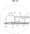
- the wire guide 172 may include a wire entrance 172a and a wire exit 172b.
- the wire 171 extending from the control panel 170 may enter the inside of the wire guide 172 through the wire entrance 172a.
- the wire 171 entered the inside of the wire guide 172 may exit the wire guide 172 through the wire exit 172b.
- the wire 171 exited the wire guide 172 through the wire exit 172b may extend to the inside of the cabinet 10.
- the wire entrance 172a may be formed at one side of the wire guide 172.
- the wire entrance 172a may be formed by cutting a portion of one side of the wire guide 172 or may be provided in a shape of a hole at one side of the wire guide 172.
- the wire exit 172b may be formed at the other side of the wire guide 172.
- the wire exit 172b may be formed by cutting a portion of the other side of the wire guide 172 or may be provided in a shape of a hole at the other side of the wire guide 172.
- the wire guide 172 may be coupled with the upper portion of the rear body 140 to guide and cover the wire 171, and cover the hinge 102.
- the top cover 173 may be coupled with the upper surface of the rear body 140.
- the control panel 170, the wire 171, and the wire guide 172 may be accommodated between the top surface of the rear body 140 and the top cover 173.
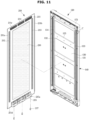
- FIG. 11 illustrates an exploded perspective view of a door coupled with a second door cover, in a shoe care apparatus according to embodiments of the invention.
- a door body 120 of FIG. 11 is the same as the door body 120 described above, and therefore, overlapping descriptions will be omitted.
- the second door cover 210 may include a second front panel 211.
- the second front panel 211 may be made of a material that is different from that of the first front panel 111.
- the second front panel 211 may be provided with various colors and/or designs, and a user may select the second front panel 211 according to his/her taste.
- the second front panel 211 may include a metal material.
- the second front panel 211 may include bending portions 211a, 211b, 211c, and 211d bent backward at its four sides.
- magnets 212 and 213, an upper trim 214, and a lower trim 215 may be provided on a rear surface of the second front panel 211. Also, on the rear surface of the second front panel 211, a buffer member 216 may be provided on the rear surface of the second front panel 211.
- the upper trim 214, the lower trim 215, and the buffer member 216 may have the same structures as or similar structures to the upper trim 114, the lower trim 115, and the buffer member 116 described above, and perform the same functions as those of the upper trim 114, the lower trim 115, and the buffer member 116.
- a fixing member 217 may be the same as the fixing member 180 described above.
- the second door cover 210 may include the magnets 212 and 213 provided on the rear surface.
- the magnets 212 and 213 may include a first magnet 212 and a second magnet 213.
- the first magnet 212 and the second magnet 213 may be arranged adjacent to both sides of the second front panel 211, and extend in the up-down direction.
- the first magnet 212 and the second magnet 213 may be coupled with a first magnet coupling portion 133 and a second magnet coupling portion 134 of the reinforcement plate 130 by a magnetic force.
- the first magnet coupling portion 133 and the second magnet coupling portion 134 may indicate some portions of the reinforcement plate 130. More specifically, the first magnet coupling portion 133 and the second magnet coupling portion 134 may indicate some areas of the reinforcement plate 130, being adjacent to the recess portions 131 and 132.
- the recess portions 131 and 132 may be positioned between the magnet coupling portions 133 and 134.
- the first magnet coupling portion 133 and the second magnet coupling portion 134 are shaded, however, the first magnet coupling portion 133 and the second magnet coupling portion 134 may be not shaded.
- the door body 120 may configure the door 100 by being selectively coupled with the first door cover 110 or the second door cover 210.
- any one of the first door cover 110 and the second door cover 210 may be coupled with the door body 120.
- the door body 120 may include the recess portions 131 and 132 to be coupled with the first door cover 110, and also, the door body 120 may include the magnet coupling portions 133 and 134 to be coupled with the second door cover 210. Accordingly, the first door cover 110 or the second door cover 210 may be coupled with the door body 120 without changing the structure of the door body 120.
Landscapes
- Engineering & Computer Science (AREA)
- Civil Engineering (AREA)
- Structural Engineering (AREA)
- Footwear And Its Accessory, Manufacturing Method And Apparatuses (AREA)
Description
- The invention relates to a shoe care apparatus, and more particularly, to a shoe care apparatus with an improved door structure.
- A shoe care apparatus is an apparatus for maintaining shoes by drying the shoes, keeping the shoes clean, or deodorizing the shoes.
- The shoe care apparatus includes a cabinet, a care room provided inside the cabinet for accommodating shoes, and a door coupled with the cabinet to open and close the care room.
- The door should have sufficient stiffness such that it is not deformed during a use process. Although there are various methods for reinforcing the stiffness of the door, a method for simplifying an assembly process while reducing material cost is described herein.
-
CN 105 831 995 A describes a shoe cabinet comprising a cabinet body and a cabinet door. The cabinet body has a rectangular cuboid shape, and the cabinet door has a flat plate shape. The cabinet body has an open end face, and the cabinet door is disposed on the open surface of the cabinet body. A magnetic closure strip is arranged between the cabinet body and the cabinet door. When the locker door is closed, the entire interior of the shoe cabinet is closed. -
JP 2021 040909 A - It is an aspect of the invention to provide a shoe care apparatus including a door capable of simplifying an assembly process while reducing material cost.
- It is another aspect of the invention to provide a shoe care apparatus capable of easily changing a design of a door.
- It is still another aspect of the invention to provide a shoe care apparatus including a door implemented by coupling a rear body provided as an injection mold with a cover plate provided as a metal material by using a rivet.
- According to one or more embodiments, a shoe care apparatus includes: a main body; a care room provided inside the main body and accommodating shoes; and a door opening and closing the care room, wherein the door includes: a front panel forming a front surface of the door, and including a side trim provided on a rear surface of the front panel or a magnet provided on the rear surface of the front panel; a rear body forming a rear surface of the door; and a reinforcement plate positioned between the front panel and the rear body, and detachably coupled with the front panel, and the reinforcement plate includes: a recess portion accommodating at least one portion of the side trim; and a magnet coupling portion coupled with the magnet by a magnetic force of the magnet, and arranged in parallel to the recess portion.
- The door may include: a first door cover including the side trim and a first front panel including a first material; or a second door cover including the magnet and a second front panel including a second material that is different from the first material.
- The door may include a bracket positioned between the reinforcement plate and the rear body, and coupled with the rear body and the reinforcement plate to couple the reinforcement plate with the rear body.
- The reinforcement plate may be coupled with the rear body by a first coupling member.
- The bracket may be coupled with the rear body by a second coupling member which is different from the first coupling member.
- At least one of the first coupling member and the second coupling member may include a rivet.
- The rear body may further include a rivet coupling portion with which the rivet is coupled, wherein the rivet coupling portion and the rear body are integrated into one body.
- The rivet coupling portion may include: a rivet hole through which the rivet passes; and a rivet support plate in which the rivet hole is formed, the rivet support plate facing the reinforcement plate.
- The rivet coupling portion may further include an accommodating space accommodating the rivet passed through the rivet hole.
- One side of the accommodating space may open.
- The recess portion may include a coupling groove in which at least one portion of the side trim is inserted.
- The side trim may be coupled with the recess portion by being inserted in the coupling groove.
- The side trim may include a pair of side trims.
- The magnet may include a pair of magnets.
- The recess portion may include a pair of recess portions accommodating at least one portion of each of the pair of side trims.
- The magnet coupling portion may include a pair of magnet coupling portions coupled with the pair of magnets by a magnetic force.
- The pair of magnet coupling portions may be positioned between the pair of recess portions.
- The door may further include: a control panel embedded into an upper portion of the door; a wire extending from the control panel to inside of the main body; and a wire guide guiding the wire and covering a portion of the wire such that the wire passes a hinge of the door and extends to the inside of the main body.
- The wire guide may include: a wire entrance formed at one side of the wire guide such that the wire extending from the control panel enters inside of the wire guide; and a wire exit formed at the other side of the wire guide such that the wire entered the inside of the wire guide extends to the inside of the main body.
- The shoe care apparatus may further include: a supply duct supplying outside air of the care room to the care room; a shoe supporter configured to support shoes, connected to the supply duct, and supplying inside air of the supply duct to the shoes; and a supporter holder supporting the shoe supporter disconnected from the supply duct, and positioned on a rear surface of the door body.
- A shoe care apparatus includes: a main body; a care room provided inside the main body and accommodating shoes; and a door opening and closing the care room, wherein the door includes: a rear body forming a rear surface of the door; a front panel forming a front surface of the door; and a reinforcement plate positioned between the rear body and the front panel, and detachably coupled with the front panel, the front panel includes a pair of side trims or a pair of magnets coupled with the reinforcement plate and protruding backward from the front panel, the reinforcement plate includes a pair of recess portions each accommodating at least one portion of each of the pair of side trims and a pair of magnet coupling portions respectively coupled with the pair of magnets by a magnetic force, and the pair of magnet coupling portions are positioned between the pair of recess portions.
- The shoe care apparatus may further include a control panel embedded into an upper portion of the door, and a user interface of the control panel may be provided on an upper surface of the door.
- The shoe care apparatus may further include a door hinge rotatably coupling the door with the main body, and a wire guide guiding a wire for supplying power to the control panel to extend toward the door hinge.
- An accessory storage portion may be provided on a door body in such a way as to protrude toward the care room upon closing of the door..
- According to one or more embodiments, a shoe care apparatus includes a door that is capable of simplifying an assembly process while reducing material cost may be provided.
- According to one or more embodiments, shoe care apparatus is capable of easily changing the design of the door may be provided.
- According to one or more embodiments, a shoe care apparatus includes a door that couples the rear body provided as an injection mold with the cover plate provided as a metal material by using a rivet may be provided.
-
-
FIG. 1 illustrates a shoe care apparatus according to embodiments of the invention; -
FIG. 2 illustrates a door open state of the shoe care apparatus shown inFIG. 1 ; -
FIG. 3 illustrates a cross-sectional view taken along line A-A' ofFIG. 1 ; -
FIG. 4 illustrates a door coupled with a first door cover, in a shoe care apparatus according to embodiments of the invention; -
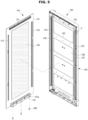
FIG. 5 illustrates the door shown inFIG. 4 separated into a door cover and a door body; -
FIG. 6 illustrates an exploded perspective view of a door body in a shoe care apparatus according to embodiments of the invention; -
FIG. 7 illustrates an enlarged view of a part D shown inFIG. 6 ; -
FIG. 8 illustrates a part of a cross section taken along line B-B' ofFIG. 4 ; -
FIG. 9 illustrates an enlarged view of a part C shown inFIG. 5 ; -
FIG. 10 illustrates a top view of a top cover separated from the door shown inFIG. 4 ; and -
FIG. 11 illustrates a door to which a second door cover is coupled separated into the second door cover and a door body, in a shoe care apparatus according to embodiments of the invention. - Configurations illustrated in the embodiments and the drawings described in the present specification are only the preferred embodiments of the invention, and thus it is to be understood that various modified examples, which may replace the embodiments and the drawings described in the present specification, are possible when filing the present application.
- Also, like reference numerals or symbols denoted in the drawings of the present specification represent members or components that perform the substantially same functions.
- Also, the terms used in the present specification are merely used to describe embodiments, and are not intended to restrict and/or limit the invention. It is to be understood that the singular forms "a," "an," and "the" include plural referents unless the context clearly dictates otherwise. It will be understood that when the terms "includes," "comprises," "including," and/or "comprising," when used in this specification, specify the presence of stated features, figures, steps, operations, components, members, or combinations thereof, but do not preclude the presence or addition of one or more other features, figures, steps, operations, components, members, or combinations thereof.
- It will be understood that, although the terms including ordinal numbers, such as "first", "second", etc., may be used herein to describe various components, these components should not be limited by these terms. These terms are only used to distinguish one component from another. For example, a first component could be termed a second component, and, similarly, a second component could be termed a first component, without departing from the scope of the invention. As used herein, the term "and/or" includes any and all combinations of one or more of associated listed items.
- In the following description, the terms "front", "rear", "left", "right", etc. are defined based on the drawings, and the shapes and positions of the corresponding components are not limited by the terms.
- Hereinafter, embodiments of the invention will be described in detail with reference to the accompanying drawings.
-
FIG. 1 illustrates a shoe care apparatus according to embodiments of the invention.FIG. 2 illustrates a door open state of the shoe care apparatus shown inFIG. 1 .FIG. 3 illustrates a cross-sectional view taken along line A-A' ofFIG. 1 . - In the present specification, a main body may indicate a cabinet.
- Referring to
FIG. 1 , the X-axis direction may be defined as a left-right direction, the Y-axis direction may be defined as a front-back direction, and the Z-axis direction may be defined as an up-down direction. - Referring to
FIGS. 1 to 3 , ashoe care apparatus 1 according to embodiments of the invention may include acabinet 10, and adoor 100 rotatably coupled with thecabinet 10. - The
cabinet 10 may be in a shape of a rectangular parallelepiped of which the front side opens. In the open front side of thecabinet 10, acabinet opening 10a may be formed. Thedoor 100 may be rotatably coupled with thecabinet 10 to open and close acare room 30 formed in thecabinet 10. Thedoor 100 may be coupled with thecabinet 10 through ahinge 102. - The
door 100 may include asupport holder 101 provided on one side facing the inside of thecare room 30 upon closing of thecare room 30. At least onesupport holder 101 may be provided. Thesupport holder 101 may easily hold ashoe supporter 50 which will be described below by hanging theshoe supporter 50 thereon. However, a use of thesupporter holder 101 is not limited to this, and thesupporter holder 101 may be used to hold other components. In the present specification, thesupporter holder 101 may be an example of an accessory storage portion. The accessory storage portion may be provided on adoor body 120 in such a way as to protrude toward thecare room 30 upon closing of thedoor 100. - The
door 100 may further include a user interface such as an inputter (not shown) provided on an upper surface of thedoor 100. A user may set various care courses through the inputter based on a kind of shoes that he/she wants to care. The inputter may include a control panel capable of receiving touch inputs, or a button capable of receiving physical pressure inputs. Acontrol panel 170 may display a progress state of a care course, state information (shoes, clothes, etc.) of an accommodated object, etc. At least one portion of the upper surface of thedoor 100 may be made of a transparent material. Accordingly, a user interface of thecontrol panel 170 embedded into an upper portion of thedoor 100 may be displayed on the upper surface of thedoor 100. Also, thecontrol panel 170 may display state information, etc. of smell sensed by asensor 13. Accordingly, a user may easily check state information of theshoe care apparatus 1 through thecontrol panel 170 without opening thedoor 100. - The
cabinet 10 may include anexternal case 11 forming an outer appearance, and aninternal case 12 installed inside theexternal case 11. Theinternal case 12 may form thecare room 30. Thecare room 30 may accommodate a plurality of shoes, clothes, etc. Below thecare room 30, amachine room 40 may be provided to supply hot and dry air to thecare room 30. - In the
cabinet 10, a flow path along which air circulates through thecare room 30 and themachine room 40 may be provided. - The
shoe supporter 50 capable of supporting shoes may be provided inside thecare room 30. Theshoe supporter 50 may be installed on one side surface of thecare room 30. InFIGS. 2 and3 , theshoe supporter 50 is shown to be located on a right side of thecare room 30. However, the location of theshoe supporter 50 is not limited to this, and theshoe supporter 50 may be located on a left side of thecare room 30 or on a rear inner side of thecare room 30. Theshoe supporter 50 may be detachable from thecabinet 10. At least oneshoe supporter 50 may be provided. Theshoe supporter 50 may have a shape of being insertable into the inside of a shoe. - In the
care room 30, asupporter rail 51 for supporting theshoe supporter 50 may be provided. Theshoe supporter 50 may be detachably attached to thesupporter rail 51. Thesupporter rail 51 may be provided on one side of theinternal case 12. Thesupporter rail 51 may be positioned to correspond to asupply opening 60 provided in one side of theinternal case 12. - The
supporter rail 51 may include arail opening 51a that is communicable with thesupply opening 60. Therail opening 51a may penetrate a body of thesupporter rail 51. Therail opening 51a may be opened or closed by asupply door 56 provided at thesupply opening 60. - The
shoe supporter 50 and thesupporter rail 51 may be located on one side of thecabinet 10 to communicate with thesupply opening 60. Theshoe supporter 50 may be connected to asupply duct 70 by communicating with thesupply opening 60. For example, theshoe supporter 50 may be located on a right side surface of thecare room 30, although not limited thereto. However, theshoe supporter 50 may be located on a left side surface of thecare room 30. - Because the
shoe supporter 50 is detachable from thecare room 30, a space of thecare room 30 for caring relatively long shoes may be secured. - In the
cabinet 10, themachine room 40 includes equipment for dehumidifying or heating inside air of thecare room 30. Themachine room 40 may be located below thecabinet 10. Themachine room 40 may be provided below thecare room 30. In themachine room 40, equipment including aheat exchanger 47 for exchanging heat with air entered themachine room 40 may be positioned to supply hot and dry air to the inside of thecare room 30. - The
machine room 40 may include aninlet 49a through which air enters themachine room 40 from thecare room 30, and anoutlet 49b through which air is discharged to thecare room 30. Air entered through theinlet 49a may be humid air. Air discharged through theoutlet 49b may be hot and dry air. - The
inlet 49a of themachine room 40 may communicate with arecovery chamber 80. Theoutlet 49b of themachine room 40 may communicate with thesupply duct 70 which will be described below. Also, at theinlet 49a of themachine room 40, a filter unit may be positioned. The filter unit may filter foreign materials from air which will enter themachine room 40. That is, the filter unit may prevent foreign materials from entering themachine room 40. For example, the filter unit may be configured with afilter frame 39 and a filter 38 installed in thefilter frame 39. - In a lower portion of the
cabinet 10, adrain fan 48 that is detachable from thecabinet 10 may be installed. Thedrain fan 48 may be adjacent to theheat exchanger 47 to easily collect condensed water generated by the heat exchanger 47 (specifically, a condenser 43). - The
heat exchanger 47 may be provided to dehumidify and/or heat inside air of themachine room 40 as necessary. Theheat exchanger 47 may heat air collected from thecare room 30 and supply hot and dry air to thecare room 30. Theheat exchanger 47 may include anevaporator 42 and thecondenser 43 through which a refrigerant circulates. Theheat exchanger 47 may dehumidify and/or heat air. - In the
machine room 40, a refrigerant cycle may be formed. The refrigerant cycle may be formed by a refrigerant circulating through acompressor 41, theevaporator 42, an expansion valve (not shown), and thecondenser 43. Theevaporator 42 may evaporate a refrigerant expanded by the expansion valve (not shown) to thereby dehumidify air entered themachine room 40. Also, thecondenser 43 may condense a refrigerant compressed by thecompressor 41 to thereby heat air passed through theevaporator 42. Accordingly, air passed through theheat exchanger 47 may become a hot and dry state. - A
blow fan 44 may cause air to smoothly enter themachine room 40 and be smoothly discharged from themachine room 40. Theblow fan 44 may be a centrifugal fan that inhales air in a direction of a rotation shaft and discharges air in a radial direction. However, a kind of theblow fan 44 is not limited to a centrifugal fan, and theblow fan 44 may be provided as an axial flow fan or a mixed flow fan. - In the
machine room 40, aconnection flow path 82 along which air passing through theevaporator 42, thecondenser 43, and theblow fan 44 flows may be formed. Theconnection flow path 82 may be formed by aconnection duct 46. One end of theconnection duct 46 may communicate with thecare room 30. The other end of theconnection duct 46 may communicate with thesupply duct 70 provided in one side wall of thecabinet 10. Theconnection duct 46 may cover at least one portion of theevaporator 42, thecondenser 43, and theblow fan 44. - The
recovery chamber 80 may be provided between thecare room 30 and themachine room 40. Therecovery chamber 80 may be a space partitioned from thecare room 30, and guide air collected from thecare room 30 to themachine room 40. More specifically, therecovery chamber 80 may guide air collected from thecare room 30 to theinlet 49a of themachine room 40. One end of therecovery chamber 80 may communicate with thecare room 30, and the other end of therecovery chamber 80 may communicate with themachine room 40. In therecovery chamber 80, arecovery flow path 81 along which air flows from thecare room 30 to themachine room 40 may be formed. - The
recovery chamber 80 may be formed by aseparation shelf 91 which will be described below. For example, therecovery chamber 80 may be a space partitioned in an up-down direction from thecare room 30 by installing theseparation shelf 91 in theinternal case 12. - In the
care room 30, thesupply opening 60 may be provided. Thesupply opening 60 may be located in the side wall of theinternal case 12. More specifically, thesupply opening 60 may be formed in the left side surface of thecare room 30 in which theshoe supporter 50 is located. However, the location of thesupply opening 60 is not limited to this, and thesupply opening 60 may be formed in the right side surface of thecare room 30 to correspond to the location of theshoe supporter 50. At least onesupply opening 60 may be formed. Thesupply opening 60 may supply hot and dry air passed through theheat exchanger 47 of themachine room 40 to the inside of thecare room 30 to dry and/or dehumidify shoes. Thesupply opening 60 may be substantially in a shape of a circle, although not limited thereto. Thesupply opening 60 may have various shapes, such as a quadrangle, a polygon, etc. - The
connection duct 46 may connect thesupply duct 70 to therecovery chamber 80. One end of theconnection duct 46 may communicate with thesupply duct 70. At the other end of theconnection duct 46, theinlet 49a of themachine room 40 may be provided. The other end of theconnection duct 46 may communicate with therecovery chamber 80. Air entered themachine room 40 through agrille 92 of theseparation shelf 91 may pass through theconnection duct 46 to be dehumidified and/or heated, and then be again discharged to thecare room 30 through thesupply duct 70 and thesupply opening 60. Thereby, shoes, clothes, etc. accommodated inside thecare room 30 may be cared (for example, dried, dehumidified, or sterilized) by hot and dry air discharged through thesupply opening 60. - The
supply duct 70 may extend in the up-down direction between theexternal case 11 and theinternal case 12 of thecabinet 10. Thesupply duct 70 may be positioned in the side of thecabinet 10 on which theshoe supporter 50 is mounted. One end of thesupply duct 70 may communicate with theconnection duct 46, and the other end of thesupply duct 70 may communicate with thesupply opening 60. Thesupply duct 70 may form asupply flow path 83 for guiding air discharged from themachine room 40 to thesupply opening 60. - The
shoe care apparatus 1 may further include a water supply container (not shown), a steam generator (not shown) configured to receive water from the water supply container and generate a steam, and a steam spray (not shown) configured to receive a steam from the steam generator and spray the steam to thecare room 30. - The water supply container may be positioned below the
care room 30. Water stored in the water supply container may be supplied to the steam generator and used to form a steam. The water supply container may be detachable from thecabinet 10 to easily add water. - The steam generator may be positioned in the
machine room 40. The steam generator may generate a steam and guide the steam to the steam spray. The steam generator may be connected to the steam spray through a steam supply pipe (not shown). - The
shoe care apparatus 1 may further include adeodorizing device 45. Thedeodorizing device 45 may be positioned inside themachine room 40. Thedeodorizing device 45 may be positioned in theconnection duct 46 to remove smell of air passing through thecare room 30. InFIG. 3 , thedeodorizing device 45 is shown to be positioned to the left of theblow fan 44. However, the location of thedeodorizing device 45 is not limited to this, and thedeodorizing device 45 may be positioned to the right of theblow fan 44. - The
deodorizing device 45 may include adeodorizing filter 45a and a sterilizinglamp 45b. Thedeodorizing filter 45a may include a ceramic filter. The sterilizinglamp 45b may include an ultraviolet lamp, although not limited thereto. However, thedeodorizing filter 45a may include various filters that are capable of removing smell of air. The sterilizinglamp 45b may include various devices that are capable of removing germs. - In the
care room 30, at least oneshelf 90 may be provided. Theshelf 90 may hold an object thereon. Thesupply opening 60 and theshoe supporter 50 may be positioned adjacent to theshelf 90. - The
shelf 90 may include aduct shelf 95. Theduct shelf 95 may include aninternal flow path 96 as shown inFIG. 3 . Heated air (or hot and dry air) passing through theinternal flow path 96 may be sprayed toward an object from each of aspray port 95a of theduct shelf 95 and aspray port 97a of acircular duct 97. Also, the heated air may pass through theinternal flow path 96 and be discharged to thecare room 30 through ashelf outlet 98. InFIG. 3 , theshelf outlet 98 is shown to be positioned in an upper side of theduct shelf 95, although not limited thereto. However, theshelf outlet 98 may be positioned in a lower side of theduct shelf 95. - The
shelf 90 may include aseparation shelf 91. Theseparation shelf 91 may form therecovery chamber 80. For example, theseparation shelf 91 may be installed in theinternal case 12 to form therecovery chamber 80 partitioned from thecare room 30. - The
separation shelf 91 may be detachably installed in thecabinet 10. That is, theseparation shelf 91 may be detachably attached to thecabinet 10. Also, to easily attach/detach theseparation shelf 91 to/from thecabinet 10, a handle (not shown) may be provided at both sides of theseparation shelf 91. - In a front portion of the
separation shelf 91, agrille 92 for collecting inside air of thecare room 30 may be formed. Thegrille 92 may form a recovery opening (not shown) for communicating thecare room 30 with therecovery chamber 80. - The
shoe care apparatus 1 may include at least onesensor 13. Thesensor 13 may sense inside smell of thecare room 30. Theshoe care apparatus 1 may display state information of the smell sensed by thesensor 13. More specifically, thecontrol panel 170 provided in thedoor 100 may display state information of smell sensed by thesensor 13. Accordingly, a user may easily check state information of smell with his/her naked eyes through thecontrol panel 170 without opening thedoor 100. - The
sensor 13 may be installed in thecare room 30 and/or theshelf 90, although not limited thereto. Thesensor 13 may be installed at any location at which thesensor 13 is capable of sensing inside smell of thecare room 30. -
FIG. 4 illustrates a door coupled with a first door cover, in a shoe care apparatus according to embodiments of the invention.FIG. 5 illustrates an exploded perspective view of a door cover and a door body of the door shown inFIG. 4 . - Referring to
FIGS. 4 and5 , in theshoe care apparatus 1 according to embodiments of the invention, thedoor 100 may be separated into adoor cover 110 and thedoor body 120. - The
door body 120 may be rotatably coupled with thecabinet 10. Thedoor body 120 may form a rear surface of thedoor 100, and thedoor cover 110 may be detachably coupled with thedoor body 120. - Hereinafter, the
door cover 110 shown inFIGS. 5 to 10 is referred to as afirst door cover 110, and adoor cover 210 shown inFIG. 11 is referred to as asecond door cover 210. - The
first door cover 110 may be detachably coupled with thedoor body 120. Thefirst door cover 110 may be coupled with thedoor body 120 to cover a front surface of thedoor body 120. Thefirst door cover 110 may form an outer appearance of thedoor 100. - The
first door cover 110 may include a firstfront panel 111. The firstfront panel 111 may be provided with various colors and/or designs, and a user may select the firstfront panel 111 according to his/her taste. The firstfront panel 111 may include a glass material. The firstfront panel 111 may be provided in a shape of a plate. - The
first door cover 110 may include side trims 112 and 113, anupper trim 114, and alower trim 115, which are provided on a rear surface of the firstfront panel 111. Also, thefirst door cover 110 may further include abuffer member 116 provided on the rear surface of thefirst door cover 110. - The side trims 112 and 113 may include a
first side trim 112 and asecond side trim 113. Thefirst side trim 112 and thesecond side trim 113 may have the same structure and be symmetrically arranged. According to embodiments of the invention, the side trims 112 and 113 may be provided as rigid bodies with little structural deformation, andrecess portions recess portions - The side trims 112 and 113 may be inserted in coupling grooves of the
recess portions recess portions recess portions - The
upper trim 114 may be positioned at an upper edge of the rear surface of the firstfront panel 111. Theupper trim 114 may be coupled with an upper trim coupling portion (a reference numeral is omitted) of thedoor body 120. Theupper trim 114 may be coupled with the upper trim coupling portion while rotating on the upper trim coupling portion as a rotation shaft. - The
lower trim 115 may be positioned at a lower edge of the rear surface of the firstfront panel 111. Thelower trim 115 may be coupled with a lower trim coupling portion (a reference numeral is omitted) of thedoor body 120. After theupper trim 114 is coupled with the upper trim coupling portion, thefirst door cover 110 may move toward thedoor body 120 and thelower trim 115 may be coupled with the lower trim coupling portion. - After the
lower trim 115 is coupled with the lower trim coupling portion, a fixingmember 180 may be coupled with a lower surface of thedoor 100 such that thefirst door cover 110 is not separated from thedoor body 120. At least one portion of the fixingmember 180 may pass through a hole (not shown) formed in the lower surface of thedoor body 120 and a fixingmember hole 115a formed in thelower trim 115 to couple thefirst door cover 110 with thedoor body 120. By coupling the fixingmember 180 with the lower surface of thedoor 100, thefirst door cover 110 may be not separated from thedoor body 120. - The
buffer member 116 may be positioned in a space formed between the firstfront panel 111 and thedoor body 120. Thebuffer member 116 may prevent an impact applied to the firstfront panel 111 from being transferred to thedoor body 120. Also, thebuffer member 116 may absorb noise that may be generated in thefirst door cover 110. Thebuffer member 116 may include expanded polystyrene. -
FIG. 6 illustrates an exploded perspective view of a door body in a shoe care apparatus according to embodiments of the invention. - Hereinafter, a configuration of the
door body 120 in theshoe care apparatus 1 according to embodiments of the invention will be described in detail with reference toFIG. 6 . - According to embodiments of the invention, the
door body 120 may include arear body 140 forming the rear surface of thedoor 100, areinforcement plate 130 coupled with therear body 140 to reinforce strength of therear body 140, and a plurality ofbrackets rear body 140 and thereinforcement plate 130 to reinforce the strength of therear body 140. - Also, the
door body 120 may further include acontrol panel 170 embedded into an upper portion of therear body 140, awire 171 electrically connecting thecontrol panel 170 to inside of thecabinet 10, and awire guide 172 guiding thewire 171. Also, thedoor body 120 may further include atop cover 173 coupled with an upper side of therear body 140 to cover thecontrol panel 170, thewire 171, and thewire guide 172. Thecontrol panel 170, thewire 171, and thewire guide 172 may be positioned in a space formed between thetop cover 173 and an upper surface of therear body 140. - The
rear body 140 may be formed by injection-molding. Accordingly, therear body 140 may be made of a nonmetal material. Therear body 140 may include arivet coupling portion 141 with which a rivet R is coupled, and ascrew coupling portion 142 with which a screw S is coupled. Therivet coupling portion 141 and thescrew coupling portion 142 may be integrated into therear body 140. Also, a plurality ofrivet coupling portions 141 may be provided, and a plurality ofscrew coupling portions 142 may be provided. - The
reinforcement plate 130 may be coupled with therear body 140 to cover a front surface of therear body 140. Thereinforcement plate 130 may reinforce the strength of therear body 140 manufactured by inj ection-molding. Thereinforcement plate 130 may be made of a metal material, or include a magnetic body. Thereinforcement plate 130 may include adepressed portion 135 for reinforcing the strength of thereinforcement plate 130. Thedepressed portion 135 may be formed by depressing a portion of thereinforcement plate 130 toward therear body 140, and a plurality ofdepressed portions 135 may be provided. - The
reinforcement plate 130 may include a plurality ofholes reinforcement plate 130 may include therecess portions reinforcement plate 130 may includemagnet coupling portions recess portions magnet coupling portions reinforcement plate 130. More specifically, themagnet coupling portions recess portions magnet coupling portions magnets reinforcement plate 130 at locations corresponding to themagnets - A pair of
recess portions magnet coupling portions recess portions magnet coupling portions reinforcement plate 130. Also, the pair ofmagnet coupling portions recess portions - The
brackets rear body 140 to reinforce the strength of therear body 140. Also, thebrackets rear body 140 and thereinforcement plate 130 to mediate coupling between therear body 140 and thereinforcement plate 130. - The
brackets first brackets rear body 140,second brackets rear body 140, andconnection brackets first brackets - The
first brackets first brackets holes first brackets reinforcement plate 130 may be coupled with therear body 140 by screws S. - The
second brackets second brackets first brackets second brackets reinforcement plate 130 may be coupled with therear body 140 by screws S. - The
connection brackets connection brackets screw holes holes 161c into which rivets R are inserted. Theconnection brackets reinforcement plate 130 by the rivets R. Also, theconnection brackets rear body 140 by screws S. - In the
reinforcement plate 130, thebrackets rear body 140, a plurality of holes may be formed. Hereinafter, coupling of thereinforcement plate 130, thebrackets rear body 140 will be described by using some of the holes as an example. - The
first holes 130a of thereinforcement plate 130 may be positioned at locations corresponding to the rivet holes 161c of theconnection bracket 161. Thereinforcement plate 130 may be coupled with theconnection bracket 161 by passing the rivets R through thefirst holes 130a and the rivet holes 161c and then riveting the rivets R. - The
second holes 130b of thereinforcement plate 130 may be positioned at locations corresponding to thelower holes 140b of therear body 140. Thereinforcement plate 130 may be coupled with therear body 140 by passing screws S through thesecond holes 130b and thelower holes 140b and screw-coupling the screws S with therear body 140. - The
third holes 130c of thereinforcement plate 130 may be positioned at locations corresponding to therivet coupling portions 141 of therear body 140. Thereinforcement plate 130 may be coupled with therear body 140 by passing rivets R through thethird holes 130c and the rivet holes 141a of therivet coupling portion 141 and then riveting the rivets R. Therivet coupling portion 141 will be described below. - The
fourth holes 130d of thereinforcement plate 130 may be coupled with the rivet holes 140d of therear body 140 by the same method by which thethird holes 130c are coupled with therivet holes 141a, and accordingly, overlapping descriptions will be omitted. -
FIG. 7 illustrates an enlarged view of a part D shown inFIG. 6 . - Hereinafter, the
rivet coupling portion 141 according to embodiments of the invention will be described in detail with reference toFIG. 7 . - Referring to
FIG. 7 , therear body 140 may be coupled with rivets R, and include therivet coupling portion 141 integrated into therear body 140. - The
rivet coupling portion 141 may include arivet hole 141a through which a rivet R passes, arivet support plate 141b in which therivet hole 141a is formed, and anaccommodating space 141c accommodating a portion of the rivet R passed through therivet hole 141a. - A diameter of the
rivet hole 141a may be greater than that of a shaft of the rivet R such that the shaft of the rivet R passes through therivet hole 141a. The diameter of therivet hole 141a may be smaller than that of a head of the rivet R such that the head of the rivet R does not pass through therivet hole 141a. Therivet hole 141a may penetrate therivet support plate 141b. - The
rivet support plate 141b may face thereinforcement plate 130. A front surface of therivet support plate 141b may be in contact with thereinforcement plate 130. - The
rivet coupling portion 141 may include theaccommodating space 141c accommodating the rivet R. A side of theaccommodating space 141c may open. Therivet coupling portion 141 may include therivet support plate 141b, andconnection plates rivet support plate 141b to therear body 140. Theaccommodating space 141c may be formed by therivet support plate 141b, theconnection plates rear body 140. An upper side of theaccommodating space 141c may open as seen inFIG. 7 . In other words, theconnection plates rivet coupling portion 141 may not exist in the upper side of theaccommodating space 141c. A direction of the upper side of theaccommodating space 141c may be defined as seen inFIG. 7 . - Because one side of the
accommodating space 141c opens, slide equipment may be taken out through the open side of theaccommodating space 141c upon injection-molding. As described above, therear body 140 may be manufactured by injection-molding, and slide equipment may be used for a reason such as undercut upon injection-molding. To take slide equipment out, a space through which the slide equipment is taken out may be used. According to embodiments of the invention, upon injection-molding of therear body 140, slide equipment may be taken out through the open side of theaccommodating space 141c. - According to a concept of the invention, the
rear body 140 manufactured by injection-molding may be coupled with thereinforcement plate 130 manufactured by pressing a metal plate by rivets. - In a case in which the
rear body 140 is an injection-molding product being not a metal material, therear body 140 may have weak strength, and accordingly, therear body 140 may be reinforced. To reinforce the strength of therear body 140, thereinforcement plate 130 may be coupled with therear body 140. There may be various methods for coupling thereinforcement plate 130 with therear body 140, however, rivet coupling may be used as a method for reducing material cost and investment cost, improving utilization of space of therear body 140, and simplifying an assembly process. - The rivet coupling may have advantages of low material cost, low process investment cost, and a simple assembly process, compared with a process using foam treatment and application of an adhesive.
- Also, screw coupling may have low utilization of space because the head of a screw occupies a larger space than that of a rivet, and an outer appearance of the
rear body 140 may be contracted by a boss portion used for screw coupling, which may deteriorate quality of the outer appearance. - According to a concept of the invention, because the
rear body 140 is coupled with thereinforcement plate 130 by rivets, thedoor 100 capable of reducing material cost and process investment cost, simplifying an assembly process, and improving utilization of space and quality of the outer appearance may be provided. - According to a concept of the invention, to couple the
rear body 140 with thereinforcement plate 130 by rivets, therear body 140 may include therivet coupling portion 141. Therivet coupling portion 141 and therear body 140 may be integrated into one body by injection-molding. Therivet coupling portion 141 may include theaccommodating space 141c in which a rivet R is accommodated, and one side of theaccommodating space 141c may open. -
FIG. 8 illustrates a part of a cross section taken along line B-B' ofFIG. 4 .FIG. 9 illustrates an enlarged view of a part C shown inFIG. 5 . - Referring to
FIG. 8 , as described above, therear body 140 may be coupled with thereinforcement plate 130 by rivets R. - Referring to
FIGS. 8 and9 , therecess portion 132 may be coupled with thereinforcement plate 130 by a rivet R. The side trim 113 of thefirst door cover 110 may be inserted into acoupling groove 132a of therecess portion 132. Upon inserting of theside trim 113 into thecoupling groove 132a, therecess portion 132 made of a flexible material may be elastically deformed. -
FIG. 10 illustrates a top view of a top cover separated from the door shown inFIG. 4 . - Referring to
FIG. 10 , in theshoe care apparatus 1 according to embodiments of the invention, thecontrol panel 170 may be embedded into an upper portion of thedoor body 120. In the upper portion of therear body 140, a preset space may be provided. Thecontrol panel 170 may be positioned in the preset space. - The
wire 171 electrically connecting thecontrol panel 170 to the inside of thecabinet 10 may extend from thecontrol panel 170 to the inside of thecabinet 10. - The
wire guide 172 may be coupled with one side of the upper portion of therear body 140 to cover thehinge 102 of thedoor 100. Thewire guide 172 may include awire entrance 172a and awire exit 172b. Thewire 171 extending from thecontrol panel 170 may enter the inside of thewire guide 172 through thewire entrance 172a. Thewire 171 entered the inside of thewire guide 172 may exit thewire guide 172 through thewire exit 172b. Also, thewire 171 exited thewire guide 172 through thewire exit 172b may extend to the inside of thecabinet 10. - The
wire entrance 172a may be formed at one side of thewire guide 172. Thewire entrance 172a may be formed by cutting a portion of one side of thewire guide 172 or may be provided in a shape of a hole at one side of thewire guide 172. - The
wire exit 172b may be formed at the other side of thewire guide 172. Thewire exit 172b may be formed by cutting a portion of the other side of thewire guide 172 or may be provided in a shape of a hole at the other side of thewire guide 172. - The
wire guide 172 may be coupled with the upper portion of therear body 140 to guide and cover thewire 171, and cover thehinge 102. - The
top cover 173 may be coupled with the upper surface of therear body 140. Thecontrol panel 170, thewire 171, and thewire guide 172 may be accommodated between the top surface of therear body 140 and thetop cover 173. -
FIG. 11 illustrates an exploded perspective view of a door coupled with a second door cover, in a shoe care apparatus according to embodiments of the invention. - Referring to
FIG. 11 , thesecond door cover 210 will be described. Adoor body 120 ofFIG. 11 is the same as thedoor body 120 described above, and therefore, overlapping descriptions will be omitted. - The
second door cover 210 may include a secondfront panel 211. The secondfront panel 211 may be made of a material that is different from that of the firstfront panel 111. The secondfront panel 211 may be provided with various colors and/or designs, and a user may select the secondfront panel 211 according to his/her taste. The secondfront panel 211 may include a metal material. - The second
front panel 211 may include bendingportions - On a rear surface of the second
front panel 211,magnets upper trim 214, and alower trim 215 may be provided. Also, on the rear surface of the secondfront panel 211, abuffer member 216 may be provided. - The
upper trim 214, thelower trim 215, and thebuffer member 216 may have the same structures as or similar structures to theupper trim 114, thelower trim 115, and thebuffer member 116 described above, and perform the same functions as those of theupper trim 114, thelower trim 115, and thebuffer member 116. A fixingmember 217 may be the same as the fixingmember 180 described above. - The
second door cover 210 may include themagnets magnets first magnet 212 and asecond magnet 213. Thefirst magnet 212 and thesecond magnet 213 may be arranged adjacent to both sides of the secondfront panel 211, and extend in the up-down direction. - The
first magnet 212 and thesecond magnet 213 may be coupled with a firstmagnet coupling portion 133 and a secondmagnet coupling portion 134 of thereinforcement plate 130 by a magnetic force. As described above, the firstmagnet coupling portion 133 and the secondmagnet coupling portion 134 may indicate some portions of thereinforcement plate 130. More specifically, the firstmagnet coupling portion 133 and the secondmagnet coupling portion 134 may indicate some areas of thereinforcement plate 130, being adjacent to therecess portions recess portions magnet coupling portions magnet coupling portion 133 and the secondmagnet coupling portion 134 are shaded, however, the firstmagnet coupling portion 133 and the secondmagnet coupling portion 134 may be not shaded. - According to a concept of the invention, the
door body 120 may configure thedoor 100 by being selectively coupled with thefirst door cover 110 or thesecond door cover 210. In other words, any one of thefirst door cover 110 and thesecond door cover 210 may be coupled with thedoor body 120. Thedoor body 120 may include therecess portions first door cover 110, and also, thedoor body 120 may include themagnet coupling portions second door cover 210. Accordingly, thefirst door cover 110 or thesecond door cover 210 may be coupled with thedoor body 120 without changing the structure of thedoor body 120.
Claims (14)
- A shoe care apparatus (1) comprising:a main body;a care room (30) provided inside the main body and configured to accommodate shoes; anda door (100) configured to open and close the care room (30),wherein the door (100) comprises:a front panel forming a front surface of the door (100), and including a side trim (112, 113) provided on a rear surface of the front panel or a magnet (212, 213) provided on the rear surface of the front panel;a rear body (140) forming a rear surface of the door (100); anda reinforcement plate (130) positioned between the front panel and the rear body (140), and detachably coupled with the front panel, andthe reinforcement plate (130) comprises:a recess portion (131, 132) configured to accommodate at least one portion of the side trim (112, 113); anda magnet coupling portion (133, 134) coupled with the magnet (212, 213) by a magnetic force of the magnet (212, 213), and arranged in parallel to the recess portion (131, 132).
- The shoe care apparatus (1) of claim 1, wherein the door (100) comprises:a first door cover (110) including the side trim (112, 113) and a first front panel (111) including a first material; ora second door cover (210) including the magnet (212, 213) and a second front panel (211) including a second material.
- The shoe care apparatus (1) of claim 1, wherein the door (100) comprises:
a bracket (151, 152, 153, 154, 161, 162) positioned between the reinforcement plate (130) and the rear body (140), and coupled with the rear body (140) and the reinforcement plate (130), the bracket (151, 152, 153, 154, 161, 162) configured to couple the reinforcement plate (130) with the rear body (140). - The shoe care apparatus (1) of claim 3, wherein:the reinforcement plate (130) is coupled with the rear body (140) by a first coupling member, andthe bracket (151, 152, 153, 154, 161, 162) is coupled with the rear body (140) by a second coupling member that is different from the first coupling member.
- The shoe care apparatus (1) of claim 4, wherein at least one of the first coupling member and the second coupling member includes a rivet.
- The shoe care apparatus (1) of claim 1, wherein the rear body (140) further comprises a rivet coupling portion (141) with which a rivet is coupled, wherein the rivet coupling portion (141) and the rear body (140) are integrated into one body.
- The shoe care apparatus (1) of claim 6, wherein the rivet coupling portion (141) comprises:a rivet hole (140d, 141a, 161c) through which the rivet passes; anda rivet support plate (141b) in which the rivet hole (140d, 141a, 161c) is formed, the rivet support plate (141b) facing the reinforcement plate (130).
- The shoe care apparatus (1) of claim 7, wherein the rivet coupling portion (141) further comprises an accommodating space (141c) configured to accommodate the rivet that passed through the rivet hole (140d, 141a, 161c), wherein one side of the accommodating space (141c) is configured to open.
- The shoe care apparatus (1) of claim 1, wherein:the recess portion (131, 132) comprises a coupling groove (132a) in which at least one portion of the side trim (112, 113) is inserted, andthe side trim (112, 113) is coupled with the recess portion (131, 132) when the side trim (112, 113) is inserted in the coupling groove (132a).
- The shoe care apparatus (1) of claim 1, wherein:the side trim (112, 113) comprises a pair of side trims (112, 113),the magnet (212, 213) comprises a pair of magnets (212, 213),the recess portion (131, 132) comprises a pair of recess portions (131, 132) each of which are configured to accommodate at least one portion of each of the pair of side trims (112, 113), andthe magnet coupling portion (133, 134) comprises a pair of magnet coupling portions (133, 134) coupled with the pair of magnets (212, 213) by a magnetic force.
- The shoe care apparatus (1) of claim 1, wherein the pair of magnet coupling portions (133, 134) are positioned between the pair of recess portions (131, 132).
- The shoe care apparatus (1) of claim 1, wherein the door (100) further comprises:a control panel (170) embedded into an upper portion of the door (100);a wire (171) extending from the control panel (170) to inside of the main body; anda wire guide (172) guiding the wire (171) and covering a portion of the wire (171) such that the wire (171) passes a hinge (102) of the door (100) and extends inside of the main body.
- The shoe care apparatus (1) of claim 12, wherein the wire guide (172) comprises:a wire entrance (172a) formed at one side of the wire guide (172) and configured to guide the wire (171) extending from the control panel (170) inside of the wire guide (172); anda wire exit (172b) formed at another side of the wire guide (172) and configured to guide the wire (171) inside of the wire guide (172) to the inside of the main body.
- The shoe care apparatus (1) of claim 1, further comprising:a supply duct (70) supplying outside air of the care room (30) to the care room (30);a shoe supporter (50) configured to support shoes, connected to the supply duct (70), and supplying inside air of the supply duct (70) to the shoes; anda supporter holder (101) supporting the shoe supporter (50) when it is disconnected from the supply duct (70), and positioned on the rear surface of the door (100).
Applications Claiming Priority (3)
| Application Number | Priority Date | Filing Date | Title |
|---|---|---|---|
| KR20210057892 | 2021-05-04 | ||
| KR1020210096977A KR102885429B1 (en) | 2021-05-04 | 2021-07-23 | Shoe care apparatus |
| PCT/KR2022/003886 WO2022234948A1 (en) | 2021-05-04 | 2022-03-22 | Shoe care apparatus |
Publications (4)
| Publication Number | Publication Date |
|---|---|
| EP4227484A1 EP4227484A1 (en) | 2023-08-16 |
| EP4227484A4 EP4227484A4 (en) | 2024-05-01 |
| EP4227484B1 true EP4227484B1 (en) | 2025-05-21 |
| EP4227484C0 EP4227484C0 (en) | 2025-05-21 |
Family
ID=83901005
Family Applications (1)
| Application Number | Title | Priority Date | Filing Date |
|---|---|---|---|
| EP22798994.4A Active EP4227484B1 (en) | 2021-05-04 | 2022-03-22 | Shoe care apparatus |
Country Status (2)
| Country | Link |
|---|---|
| US (2) | US12279738B2 (en) |
| EP (1) | EP4227484B1 (en) |
Families Citing this family (1)
| Publication number | Priority date | Publication date | Assignee | Title |
|---|---|---|---|---|
| US11805966B1 (en) * | 2022-08-05 | 2023-11-07 | Carlos Valdes | Footwear drying device and methods of making and using the same |
Family Cites Families (19)
| Publication number | Priority date | Publication date | Assignee | Title |
|---|---|---|---|---|
| KR200146676Y1 (en) | 1994-02-25 | 1999-06-15 | 전주범 | Door opening and closing device of clothes dryer |
| KR100234992B1 (en) | 1997-06-30 | 1999-12-15 | 전주범 | Door cabinet for refrigerator |
| KR102001145B1 (en) | 2012-06-12 | 2019-10-21 | 엘지전자 주식회사 | Door for a refrigerator and method for manufacturing a door, metal container and method for manufacturing the same, method for processing a metal sheet, and apparatus for processing a metal sheet |
| KR102025734B1 (en) | 2012-11-09 | 2019-09-27 | 삼성전자주식회사 | Refrigerator and method of making the inner door thereof |
| KR101668707B1 (en) | 2015-03-06 | 2016-10-24 | 엘지전자 주식회사 | Door for Refrigerator |
| CN105831995B (en) * | 2016-05-25 | 2018-10-09 | 中山进成环保科技有限公司 | Shoe cabinet |
| JP6748843B2 (en) * | 2016-06-27 | 2020-09-02 | パナソニックIpマネジメント株式会社 | refrigerator |
| KR102627704B1 (en) | 2018-08-20 | 2024-01-23 | 삼성전자주식회사 | Clothes Care Device |
| KR102650961B1 (en) | 2018-09-12 | 2024-03-26 | 삼성전자주식회사 | Clothes care apparatus |
| KR102312667B1 (en) | 2019-04-15 | 2021-10-15 | 삼성전자주식회사 | Refrigerator |
| KR102809589B1 (en) | 2019-07-17 | 2025-05-20 | 삼성전자주식회사 | Clothes Care Device |
| KR102653613B1 (en) | 2019-08-06 | 2024-04-01 | 엘지전자 주식회사 | Shoe care apparatus and shoe care method using the same |
| WO2021049846A1 (en) | 2019-09-10 | 2021-03-18 | Samsung Electronics Co., Ltd. | Shoe dryer and control method thereof |
| JP2021040909A (en) * | 2019-09-10 | 2021-03-18 | 三星電子株式会社Samsung Electronics Co.,Ltd. | Shoe dryer and its control method |
| KR102756975B1 (en) | 2019-12-30 | 2025-01-21 | 삼성전자주식회사 | Shoe care apparatus |
| WO2021172904A1 (en) | 2020-02-25 | 2021-09-02 | 엘지전자 주식회사 | Refrigerator |
| KR20210112770A (en) | 2020-03-06 | 2021-09-15 | 엘지전자 주식회사 | refrigerator |
| KR20210156166A (en) | 2020-06-17 | 2021-12-24 | 엘지전자 주식회사 | Refrigerator |
| AU2021204021B2 (en) | 2020-06-17 | 2023-06-29 | Lg Electronics Inc. | Refrigerator |
-
2022
- 2022-03-22 EP EP22798994.4A patent/EP4227484B1/en active Active
- 2022-05-02 US US17/734,151 patent/US12279738B2/en active Active
-
2025
- 2025-02-20 US US19/059,083 patent/US20250185878A1/en active Pending
Also Published As
| Publication number | Publication date |
|---|---|
| US12279738B2 (en) | 2025-04-22 |
| EP4227484A1 (en) | 2023-08-16 |
| EP4227484A4 (en) | 2024-05-01 |
| US20220354340A1 (en) | 2022-11-10 |
| US20250185878A1 (en) | 2025-06-12 |
| EP4227484C0 (en) | 2025-05-21 |
Similar Documents
| Publication | Publication Date | Title |
|---|---|---|
| AU2022209319B2 (en) | Clothes treatment apparatus | |
| EP4290005A2 (en) | Clothes care apparatus | |
| EP4023809B1 (en) | Dryer | |
| KR102809589B1 (en) | Clothes Care Device | |
| CN105714541B (en) | Device for clothing processing | |
| EP3722495B1 (en) | Clothes treatment apparatus | |
| US20250185878A1 (en) | Shoe care apparatus | |
| KR20200141302A (en) | Iron device, clothes care apparatus and control method thereof | |
| KR20150059319A (en) | Clothes Treating Apparatus | |
| KR20220069779A (en) | Dryer | |
| KR20210056307A (en) | Fabric treating apparatus | |
| KR102885429B1 (en) | Shoe care apparatus | |
| KR20140095742A (en) | Laundry Machine | |
| KR102926882B1 (en) | A laundry treating apparatus | |
| KR20160106293A (en) | Laundry Treating Apparatus | |
| CN116568197A (en) | Shoe Care Equipment | |
| KR20140095740A (en) | Laundry Machine | |
| KR102953290B1 (en) | A laundry treatment apparatus and assembly method of the same | |
| KR20240161991A (en) | Fabric treating apparatus | |
| WO2022234948A1 (en) | Shoe care apparatus | |
| CN116457524A (en) | Drying machine | |
| US20250151895A1 (en) | Laundry treating apparatus | |
| KR102845092B1 (en) | A laundry treatment apparatus and assembly method of the same | |
| KR102841293B1 (en) | A laundry treatment apparatus and assembly method of the same | |
| CN118946693A (en) | Clothes treatment device |
Legal Events
| Date | Code | Title | Description |
|---|---|---|---|
| STAA | Information on the status of an ep patent application or granted ep patent |
Free format text: STATUS: THE INTERNATIONAL PUBLICATION HAS BEEN MADE |
|
| PUAI | Public reference made under article 153(3) epc to a published international application that has entered the european phase |
Free format text: ORIGINAL CODE: 0009012 |
|
| STAA | Information on the status of an ep patent application or granted ep patent |
Free format text: STATUS: REQUEST FOR EXAMINATION WAS MADE |
|
| 17P | Request for examination filed |
Effective date: 20230512 |
|
| AK | Designated contracting states |
Kind code of ref document: A1 Designated state(s): AL AT BE BG CH CY CZ DE DK EE ES FI FR GB GR HR HU IE IS IT LI LT LU LV MC MK MT NL NO PL PT RO RS SE SI SK SM TR |
|
| A4 | Supplementary search report drawn up and despatched |
Effective date: 20240402 |
|
| RIC1 | Information provided on ipc code assigned before grant |
Ipc: E06B 3/82 20060101ALI20240325BHEP Ipc: A47L 23/20 20060101ALI20240325BHEP Ipc: A43D 3/14 20060101ALI20240325BHEP Ipc: E06B 3/70 20060101AFI20240325BHEP |
|
| DAV | Request for validation of the european patent (deleted) | ||
| DAX | Request for extension of the european patent (deleted) | ||
| GRAP | Despatch of communication of intention to grant a patent |
Free format text: ORIGINAL CODE: EPIDOSNIGR1 |
|
| STAA | Information on the status of an ep patent application or granted ep patent |
Free format text: STATUS: GRANT OF PATENT IS INTENDED |
|
| INTG | Intention to grant announced |
Effective date: 20241219 |
|
| GRAS | Grant fee paid |
Free format text: ORIGINAL CODE: EPIDOSNIGR3 |
|
| GRAA | (expected) grant |
Free format text: ORIGINAL CODE: 0009210 |
|
| STAA | Information on the status of an ep patent application or granted ep patent |
Free format text: STATUS: THE PATENT HAS BEEN GRANTED |
|
| AK | Designated contracting states |
Kind code of ref document: B1 Designated state(s): AL AT BE BG CH CY CZ DE DK EE ES FI FR GB GR HR HU IE IS IT LI LT LU LV MC MK MT NL NO PL PT RO RS SE SI SK SM TR |
|
| REG | Reference to a national code |
Ref country code: GB Ref legal event code: FG4D |
|
| REG | Reference to a national code |
Ref country code: CH Ref legal event code: EP |
|
| REG | Reference to a national code |
Ref country code: DE Ref legal event code: R096 Ref document number: 602022015039 Country of ref document: DE |
|
| REG | Reference to a national code |
Ref country code: IE Ref legal event code: FG4D |
|
| U01 | Request for unitary effect filed |
Effective date: 20250619 |
|
| U07 | Unitary effect registered |
Designated state(s): AT BE BG DE DK EE FI FR IT LT LU LV MT NL PT RO SE SI Effective date: 20250630 |
|
| PG25 | Lapsed in a contracting state [announced via postgrant information from national office to epo] |
Ref country code: ES Free format text: LAPSE BECAUSE OF FAILURE TO SUBMIT A TRANSLATION OF THE DESCRIPTION OR TO PAY THE FEE WITHIN THE PRESCRIBED TIME-LIMIT Effective date: 20250521 |
|
| PG25 | Lapsed in a contracting state [announced via postgrant information from national office to epo] |
Ref country code: NO Free format text: LAPSE BECAUSE OF FAILURE TO SUBMIT A TRANSLATION OF THE DESCRIPTION OR TO PAY THE FEE WITHIN THE PRESCRIBED TIME-LIMIT Effective date: 20250821 Ref country code: GR Free format text: LAPSE BECAUSE OF FAILURE TO SUBMIT A TRANSLATION OF THE DESCRIPTION OR TO PAY THE FEE WITHIN THE PRESCRIBED TIME-LIMIT Effective date: 20250822 |
|
| PG25 | Lapsed in a contracting state [announced via postgrant information from national office to epo] |
Ref country code: PL Free format text: LAPSE BECAUSE OF FAILURE TO SUBMIT A TRANSLATION OF THE DESCRIPTION OR TO PAY THE FEE WITHIN THE PRESCRIBED TIME-LIMIT Effective date: 20250521 |
|
| PG25 | Lapsed in a contracting state [announced via postgrant information from national office to epo] |
Ref country code: HR Free format text: LAPSE BECAUSE OF FAILURE TO SUBMIT A TRANSLATION OF THE DESCRIPTION OR TO PAY THE FEE WITHIN THE PRESCRIBED TIME-LIMIT Effective date: 20250521 |
|
| PG25 | Lapsed in a contracting state [announced via postgrant information from national office to epo] |
Ref country code: RS Free format text: LAPSE BECAUSE OF FAILURE TO SUBMIT A TRANSLATION OF THE DESCRIPTION OR TO PAY THE FEE WITHIN THE PRESCRIBED TIME-LIMIT Effective date: 20250821 |
|
| PG25 | Lapsed in a contracting state [announced via postgrant information from national office to epo] |
Ref country code: IS Free format text: LAPSE BECAUSE OF FAILURE TO SUBMIT A TRANSLATION OF THE DESCRIPTION OR TO PAY THE FEE WITHIN THE PRESCRIBED TIME-LIMIT Effective date: 20250921 |
|
| PG25 | Lapsed in a contracting state [announced via postgrant information from national office to epo] |
Ref country code: SM Free format text: LAPSE BECAUSE OF FAILURE TO SUBMIT A TRANSLATION OF THE DESCRIPTION OR TO PAY THE FEE WITHIN THE PRESCRIBED TIME-LIMIT Effective date: 20250521 |
|
| PG25 | Lapsed in a contracting state [announced via postgrant information from national office to epo] |
Ref country code: CZ Free format text: LAPSE BECAUSE OF FAILURE TO SUBMIT A TRANSLATION OF THE DESCRIPTION OR TO PAY THE FEE WITHIN THE PRESCRIBED TIME-LIMIT Effective date: 20250521 |
|
| PG25 | Lapsed in a contracting state [announced via postgrant information from national office to epo] |
Ref country code: SK Free format text: LAPSE BECAUSE OF FAILURE TO SUBMIT A TRANSLATION OF THE DESCRIPTION OR TO PAY THE FEE WITHIN THE PRESCRIBED TIME-LIMIT Effective date: 20250521 |
|
| PLBE | No opposition filed within time limit |
Free format text: ORIGINAL CODE: 0009261 |
|
| STAA | Information on the status of an ep patent application or granted ep patent |
Free format text: STATUS: NO OPPOSITION FILED WITHIN TIME LIMIT |
|
| REG | Reference to a national code |
Ref country code: CH Ref legal event code: L10 Free format text: ST27 STATUS EVENT CODE: U-0-0-L10-L00 (AS PROVIDED BY THE NATIONAL OFFICE) Effective date: 20260402 |
|
| PGFP | Annual fee paid to national office [announced via postgrant information from national office to epo] |
Ref country code: GB Payment date: 20260224 Year of fee payment: 5 |
|
| 26N | No opposition filed |
Effective date: 20260224 |
|
| U20 | Renewal fee for the european patent with unitary effect paid |
Year of fee payment: 5 Effective date: 20260323 |