EP4227468A1 - Work vehicle - Google Patents
Work vehicle Download PDFInfo
- Publication number
- EP4227468A1 EP4227468A1 EP21879768.6A EP21879768A EP4227468A1 EP 4227468 A1 EP4227468 A1 EP 4227468A1 EP 21879768 A EP21879768 A EP 21879768A EP 4227468 A1 EP4227468 A1 EP 4227468A1
- Authority
- EP
- European Patent Office
- Prior art keywords
- image
- work vehicle
- obstacle
- alarm information
- display area
- Prior art date
- Legal status (The legal status is an assumption and is not a legal conclusion. Google has not performed a legal analysis and makes no representation as to the accuracy of the status listed.)
- Pending
Links
Images



Classifications
-
- E—FIXED CONSTRUCTIONS
- E02—HYDRAULIC ENGINEERING; FOUNDATIONS; SOIL SHIFTING
- E02F—DREDGING; SOIL-SHIFTING
- E02F9/00—Component parts of dredgers or soil-shifting machines, not restricted to one of the kinds covered by groups E02F3/00 - E02F7/00
- E02F9/26—Indicating devices
- E02F9/261—Surveying the work-site to be treated
-
- E—FIXED CONSTRUCTIONS
- E02—HYDRAULIC ENGINEERING; FOUNDATIONS; SOIL SHIFTING
- E02F—DREDGING; SOIL-SHIFTING
- E02F9/00—Component parts of dredgers or soil-shifting machines, not restricted to one of the kinds covered by groups E02F3/00 - E02F7/00
- E02F9/26—Indicating devices
-
- E—FIXED CONSTRUCTIONS
- E02—HYDRAULIC ENGINEERING; FOUNDATIONS; SOIL SHIFTING
- E02F—DREDGING; SOIL-SHIFTING
- E02F9/00—Component parts of dredgers or soil-shifting machines, not restricted to one of the kinds covered by groups E02F3/00 - E02F7/00
- E02F9/24—Safety devices, e.g. for preventing overload
-
- G—PHYSICS
- G06—COMPUTING OR CALCULATING; COUNTING
- G06T—IMAGE DATA PROCESSING OR GENERATION, IN GENERAL
- G06T7/00—Image analysis
- G06T7/10—Segmentation; Edge detection
-
- G—PHYSICS
- G06—COMPUTING OR CALCULATING; COUNTING
- G06T—IMAGE DATA PROCESSING OR GENERATION, IN GENERAL
- G06T7/00—Image analysis
- G06T7/10—Segmentation; Edge detection
- G06T7/11—Region-based segmentation
-
- G—PHYSICS
- G06—COMPUTING OR CALCULATING; COUNTING
- G06T—IMAGE DATA PROCESSING OR GENERATION, IN GENERAL
- G06T7/00—Image analysis
- G06T7/70—Determining position or orientation of objects or cameras
-
- G—PHYSICS
- G06—COMPUTING OR CALCULATING; COUNTING
- G06V—IMAGE OR VIDEO RECOGNITION OR UNDERSTANDING
- G06V20/00—Scenes; Scene-specific elements
- G06V20/50—Context or environment of the image
- G06V20/56—Context or environment of the image exterior to a vehicle by using sensors mounted on the vehicle
- G06V20/58—Recognition of moving objects or obstacles, e.g. vehicles or pedestrians; Recognition of traffic objects, e.g. traffic signs, traffic lights or roads
-
- H—ELECTRICITY
- H04—ELECTRIC COMMUNICATION TECHNIQUE
- H04N—PICTORIAL COMMUNICATION, e.g. TELEVISION
- H04N7/00—Television systems
- H04N7/18—Closed-circuit television [CCTV] systems, i.e. systems in which the video signal is not broadcast
-
- H—ELECTRICITY
- H04—ELECTRIC COMMUNICATION TECHNIQUE
- H04N—PICTORIAL COMMUNICATION, e.g. TELEVISION
- H04N7/00—Television systems
- H04N7/18—Closed-circuit television [CCTV] systems, i.e. systems in which the video signal is not broadcast
- H04N7/181—Closed-circuit television [CCTV] systems, i.e. systems in which the video signal is not broadcast for receiving images from a plurality of remote sources
-
- B—PERFORMING OPERATIONS; TRANSPORTING
- B60—VEHICLES IN GENERAL
- B60Y—INDEXING SCHEME RELATING TO ASPECTS CROSS-CUTTING VEHICLE TECHNOLOGY
- B60Y2200/00—Type of vehicle
- B60Y2200/40—Special vehicles
- B60Y2200/41—Construction vehicles, e.g. graders, excavators
- B60Y2200/412—Excavators
-
- G—PHYSICS
- G06—COMPUTING OR CALCULATING; COUNTING
- G06T—IMAGE DATA PROCESSING OR GENERATION, IN GENERAL
- G06T2207/00—Indexing scheme for image analysis or image enhancement
- G06T2207/30—Subject of image; Context of image processing
- G06T2207/30248—Vehicle exterior or interior
- G06T2207/30252—Vehicle exterior; Vicinity of vehicle
- G06T2207/30261—Obstacle
Definitions
- the present invention relates to a work vehicle.
- Patent Literature 1 discloses a system which captures images of a state around the excavator, displays the captured images on a display, as well as highlights the areas of people in the above mentioned images by surrounding them with a frame line.
- Patent Literature 1 Japanese Patent Laid-open Publication No. 2017-101420
- the present invention has been made to solve the above mentioned problem, and an object of the present invention is to provide a work vehicle capable of easily letting an operator of the work vehicle intuitively know the presence of an obstacle around the work vehicle when looking at the display, thereby easily letting the operator know danger such as a collision between the work vehicle and the obstacle.
- a work vehicle which includes: a monitoring unit that captures an image around the work vehicle and detects whether or not an obstacle is present around the work vehicle, thereby to monitor a state around the work vehicle; and a display unit to display the image obtained by the monitoring unit, wherein the display unit has: an image display area that displays the image; and an alarm information display area that displays alarm information indicating a presence of the obstacle when the monitoring unit detects that the obstacle is present, the alarm information display area is located outside the image display area in the display unit.
- the alarm information display area is located outside the image display area, so that the alarm information indicating the presence of the obstacle can be clearly and largely displayed outside the image display area.
- FIG. 1 is a side view showing a schematic configuration of a hydraulic excavator 1 which is an example of a work vehicle according to the present embodiment.
- the hydraulic excavator 1 includes a lower traveling body 2, a work machine 3, and an upper revolving body 4.
- directions are defined as follows.
- a front-rear direction the direction in which the lower traveling body 2 travels straight ahead is defined as a front-rear direction, one and other sides thereof are defined as “front” and “rear”, respectively.
- a blade 23 side with respect to a traveling motor 22 is exemplarily shown as "front”.
- a horizontal direction perpendicular to the front-rear direction is defined as a left-right direction.
- left and right sides are defined as “left” and “right”, respectively.
- a direction of gravity perpendicular to the front-rear and left-right directions is defined as a vertical direction, and upstream and downstream sides of the direction of gravity are defined as “up” and “down”, respectively.
- the lower traveling body 2 is driven by power from an engine 40 to cause the hydraulic excavator 1 to travel.
- the lower traveling body 2 is equipped with a pair of crawlers 21 on each side and a pair of traveling motors 22 on each side.
- Each of the traveling motors 22 is a hydraulic motor.
- the traveling motors 22 on each side drive the crawlers 21 on each side, respectively, and it allows the hydraulic excavator 1 to move forward and backward.
- the lower traveling body 2 is provided with the blade 23 for performing ground leveling work, and a blade cylinder 23a.
- the blade cylinder 23a is a hydraulic cylinder to rotate the blade 23 in the vertical direction.
- the work machine 3 is driven by power from an engine 40 and performs excavation work to dig out earth and sand.
- the work machine 3 has a boom 31, an arm 32, and a bucket 33.
- the boom 31, arm 32, and bucket 33 can be driven independently to perform digging operations.
- the boom 31 is rotated by a boom cylinder 31a.
- Abase end portion of the boom cylinder 31a is supported by a front portion of the upper revolving body 4 and the boom cylinder can move in a freely extendable manner.
- the arm 32 is rotated by an arm cylinder 32a.
- a base end portion of the arm cylinder 32a is supported by a tip of the boom 31 and the arm cylinder can move in a freely extendable manner.
- the bucket 33 is rotated by a bucket cylinder 33a.
- a base end portion of the bucket cylinder 33a is supported by a tip of the arm 32 and the bucket cylinder can move in a freely extendable manner.
- Each of the boom cylinder 31a, the arm cylinder 32a, and the bucket cylinder 33a is composed of a hydraulic cylinder.
- the bucket 33 is a container-like component with claws for digging, located at the tip of the work machine 3.
- the bucket 33 is pivotably attached to the tip of the arm 32 via a pin 34.
- the bucket 33 is connected to the bucket cylinder 33a via a link mechanism 35.
- a hook 36 for crane work is attached to the tip of arm 32.
- the hook 36 is a hook-shaped member for the crane work and is pivotably attached to the link mechanism 35.
- the crane work refers to lifting work in which an object to be worked is lifted up or down.
- the hook 36 is pivotably supported by the shaft of the link mechanism 35 as a turning fulcrum, and can change its posture between an extending state (see FIG. 1 ) where the hook extends from the bucket 33 and a retracting state (not shown) where the hook retracts to the bucket 33 side. For example, when performing excavation work with the bucket 33, the hook 36 comes to be in the retracting state. On the other hand, when performing the crane work with the hook 36, the hook 36 comes to be in the extending state.
- the upper revolving body 4 is configured to be revolvable relative to the lower traveling body 2 via a swing bearing (not shown).
- An operation section 41, a revolving table 42, a revolving motor 43, an engine room 44, etc. are arranged in the upper revolving body 4.
- the upper revolving body 4 is driven by the revolving motor 43 which is a hydraulic motor to revolve via the swing bearing.
- the revolving motor 43 which is a hydraulic motor to revolve via the swing bearing.
- a plurality of hydraulic pumps P0 see FIG. 2
- the engine 40 to provide power to various parts.
- Each of the hydraulic pumps P0 supplies hydraulic oil (pressure oil) to a hydraulic motor (e.g., right and left traveling motors 22 and the revolving motor 43) and a hydraulic cylinder (e.g., the blade cylinder 23a, the boom cylinder 31a, the arm cylinder 32a, the bucket cylinder 33a).
- the hydraulic motor and the hydraulic cylinder which are driven with the hydraulic oil supplied from any of the hydraulic pumps P0, are collectively referred to as a hydraulic actuator AC (see FIG. 2 ).
- An operator's seat 41a on which the operator rides is located in the operation section 41.
- a manipulation unit 41b is placed around the operator's seat 41a (especially forward, left and right side).
- the manipulation unit 41b consists of an operation lever, a switch, a button, etc. to drive the hydraulic actuator AC. Sitting on the operator's seat 41a and operating the manipulation unit 41b, the operator can actuate the hydraulic actuator AC. This allows the operator to perform the traveling of the lower traveling body 2, the ground leveling work by the blade 23, the excavation work and crane work by the work machine 3, and the revolving of the upper revolving body 4, etc.
- FIG. 2 schematically shows a configuration of a main part of the hydraulic excavator 1.
- the hydraulic excavator 1 further includes a monitoring unit 50, a controller 60, a monitor 70, a rotary lamp 81, a light emitter 82, and a sounding unit 83.
- the monitoring unit 50 detects whether or not an obstacle is present around the hydraulic excavator 1, thereby to monitor a state therearound.
- the obstacle may include an object to be monitored, such as a human, an object, or an animal.
- the hydraulic excavator 1 is provided with the monitoring unit 50 to monitor the state around the hydraulic excavator 1.
- the monitoring unit 50 captures an image around the hydraulic excavator 1 and detects whether or not the obstacle is present around the hydraulic excavator 1, thereby to monitor the state around the hydraulic excavator 1.
- the monitoring unit 50 has the following configuration.
- the monitoring unit 50 has an image capturing unit 51, an image processor 52, and an overhead image generation unit 53.
- the image capturing unit 51 includes a right camera 51a, a left camera 51b, and a rear camera 51c, which capture images of a right side, left side, and rear of the hydraulic excavator 1, respectively.
- the monitoring unit 50 has the image capturing unit 51 to capture the images.
- the image capturing unit 51 includes a plurality of cameras (right camera 51a, left camera 51b, and rear camera 51c) which capture images around the hydraulic excavator 1.
- the image capturing unit 51 captures a moving image, for example, but it may capture a still image at a predetermined frame cycle.
- the image processor 52 performs image recognition processing on an image (e.g., a right side image) captured by the image capturing unit 51 as an input, thereby to detect whether an object in the above mentioned image is an obstacle and a type of the obstacle (human/object/animal) and detect objects invading into a monitoring area.
- the monitoring unit 50 has an image processor 52 to detect whether or not the obstacles is present around the hydraulic excavator 1 by performing the image recognition processing on the images captured by the image capturing unit 51.
- the image processor 52 further detects the type of obstacle by means of the above mentioned image recognition processing.
- the overhead image generation unit 53 generates an overhead image (bird's-eye view image) centering around the hydraulic excavator 1 by performing the image processing on a plurality of images captured by a plurality of cameras (right camera 51a, left camera 51b, rear camera 51c) of the image capturing unit 51.
- the monitoring unit 50 has the overhead image generation unit 53 to generate the overhead image by performing the image processing on the plurality of images captured by the plurality of cameras.
- the image processor 52 and the overhead image generation unit 53 described above consist of a central processing unit called a CPU (Central Processing Unit) or a computing device such as a GPU (Graphics Processing Unit), for example.
- CPU Central Processing Unit
- GPU Graphics Processing Unit
- the system may also be configured to detect obstacles using an obstacle sensor instead of a camera.
- the obstacle sensor any known distance measuring device capable of acquiring distance information of the obstacle can be applied.
- an ultrasonic radar using ultrasonic waves, a millimeter wave radar using millimeter wave band radio waves, a LIDER that measures a scattered light in response to laser radiation thereby to calculate a distance, and a stereo camera which is provided with plural cameras and measures the distance from a taken image to an object can be used as the obstacle sensor.
- the position information of an obstacle can be obtained based on the phase difference information of the light emission/reception timing when the light is emitted, and the presence of an obstacle can be determined based on the light intensity information when the light is received.
- the monitoring unit 50 also monitors a state around the hydraulic excavator 1 in a plurality of monitoring segments which are segmented according to each distance from the hydraulic excavator 1.
- the image processor 52 can detect obstacles based on the above mentioned images and obtain the distance of the obstacle from the hydraulic excavator 1 by means of the image processing. If the monitoring range around the hydraulic excavator 1 is divided into two monitoring segments, D1 and D2, where D1 is a monitoring segment having a radius of less than 2m centering around the hydraulic excavator 1 and D2 is a monitoring segment having a radius from 2m to 3m, the image processor 52 can determine which of the two monitoring segments, D1 and D2, the detected obstacle belongs to based on the distance of the obstacle from the hydraulic excavator 1.
- the monitoring unit 50 can monitor whether or not obstacles are present in the multiple monitoring segments D1 and D2.
- the monitoring unit 50 may obtain the distance of the obstacle from the hydraulic excavator 1 by the obstacle sensor described above, and determine which of the two monitoring segments, D1 and D2, the detected obstacle belongs to.
- the controller 60 controls operation of each part of the hydraulic excavator 1.
- Such the controller 60 is configured as an electronic control unit referred as to an ECU (Electronic Control Unit).
- the controller 60 may include a storage unit.
- the storage unit stores a program and various information to run the controller 60.
- a RAM Random Access Memory
- ROM Read Only Memory
- the monitor 70 is located in the vicinity of (e.g., diagonally forward of) the operator's seat 41a and displays various types of information to provide necessary information to the operator sitting on the operator's seat 41a.
- the monitor 70 has a display unit 71 and an input 72.
- the monitor 70 itself may have an ECU (monitor ECU) inside, and it may be configured so that the monitor ECU controls each part of the monitor 70.
- the display unit 71 consists of a liquid crystal display device to display various types of information, for example.
- the display unit 71 displays an image obtained by the monitoring unit 50.
- the hydraulic excavator 1 includes a display unit 71 to display the image obtained by the monitoring unit 50.
- the display unit 71 also displays alarm information indicating the presence of an obstacle when the monitoring unit 50 detects that the obstacle is present around the hydraulic excavator 1.
- a display screen of the display unit 71 is described in more detail below.
- the operator can operate the input 72 to set and input various types of information.
- the input 72 consists of a touch panel input device which is superimposed on the display unit 71, for example.
- the input 72 may consist of mechanical input buttons or a jog dial.
- the display screen of the display unit 71 can also be switched (e.g., between a screen shown in FIG. 4 and a screen shown in FIG. 6 ) by the operator operating the input 72 (e.g., pressing a predetermined position).
- a rotary lamp 81 shown in FIG. 2 consists of a lamp which rotates when the monitoring unit 50 detects the obstacle.
- Alight emitter 82 consists of, for example, a light-emitting diode (LED) which lights up or blinks when the monitoring unit 50 detects the obstacle.
- a sounding unit 83 consists of a buzzer which makes a sound when the monitoring unit 50 detects the obstacle.
- the sounding unit 83 may consist of an audio output unit which outputs voice (electronic sound) when the monitoring unit 50 detects the obstacle.
- the rotation of the rotary lamp 81, the lighting up (or blinking) of the light emitter 82, and the output of a buzzer sound or voice of the sounding unit 63 allow the operator to recognize that the monitoring unit 50 detects the obstacle.
- the display unit 71 of the monitor 70, the rotary lamp 81, the light emitter 82, and the sounding unit 83 issues an alarm by displaying an icon or the like, rotating a lamp, emitting light, or making a sound, respectively, when the monitoring unit 50 detects the obstacle. Accordingly, it can be said that the display unit 71, the rotary lamp 81, the light emitter 82, and the sounding unit 83 constitute an alarm device 90 which issues an alarm based on the monitoring result of the monitoring unit 50.
- the hydraulic excavator 1 includes the alarm device 90 which issues an alarm based on the monitoring result of the monitoring unit 50.
- the alarm device 90 only has to include at least one of the display unit 71, the rotary lamp 81, the light emitter 82, and the sounding unit 83, not necessarily all of them.
- the hydraulic excavator 1 includes a plurality of hydraulic actuators AC, a hydraulic pump P0 which pumps pressure oil to the plurality of hydraulic actuators AC, and a pilot pump PP.
- FIG. 2 shows a hydraulic circuit corresponding to one hydraulic actuator AC, but a similar hydraulic circuit is configured for another hydraulic actuator AC.
- the plurality of hydraulic actuators AC consists of right and left traveling motors 22 which are hydraulic actuators for traveling to drive the lower traveling body 2, the blade cylinder 23a which is a hydraulic actuator to rotate the blade 23 vertically, the revolving motor 43 which is a hydraulic actuator for revolving to drive the upper revolving body 4, and the boom cylinder 31a, arm cylinder 32a and bucket cylinder 33a each of which is a hydraulic actuator for work to drive the work machine 3.
- the blade cylinder 23a, the boom cylinder 31a, the arm cylinder 32a, and the bucket cylinder 33a are collectively referred to as a hydraulic cylinder CY
- the hydraulic excavator 1 may be configured so as to have a so-called boom swing function which swings the work machine 3 (boom 31) in a right-left direction relative to the upper revolving body 4.
- the hydraulic cylinder CY also includes a swing cylinder which is a hydraulic actuator to swing the boom 31.
- the boom swing function is applied to a mini excavator (small hydraulic excavator) used for construction in a narrow place.
- the plurality of hydraulic pumps P0 consist of a variable displacement pump and a fixed displacement pump, and is driven by the engine 40.
- the variable displacement pump pumps the pressure oil to the right and left traveling motors 22, the boom cylinder 31a, the arm cylinder 32a and the bucket cylinder 33a.
- the fixed displacement pump supplies the pressure oil to the blade cylinder 23a, the revolving motor 43, and a swing cylinder (not shown).
- the direction switching valve CV is a pilot-type direction switching valve to switch the direction and flow rate of the pressure oil pumped from the hydraulic pump P0 (variable displacement pump or fixed displacement pump), also called a control valve.
- the direction switching valve CV according to the present embodiment include, for example, a direction switching valve corresponding to the right and left traveling motors 22, a direction switching valve corresponding to the boom cylinder 31a, a direction switching valve corresponding to the arm cylinder 32a, a direction switching valve corresponding to the bucket cylinder 33a, a direction switching valve corresponding to the blade cylinder 23a, a direction switching valve corresponding to the revolving motor 43, and a direction switching valve corresponding to the swing cylinder.
- the pilot pump PP discharges pilot oil which serves as an input order to the direction switching valve CV
- the pilot pump PP driven by the engine 40 discharges the pressure oil, thereby to generate pilot pressure in a pilot oil path.
- the hydraulic excavator 1 is provided with the pilot oil paths leading to each of the direction switching valves CV from the pilot pump PP.
- the manipulation unit 41b has a remote control valve RV for switching the direction and pressure of the pressure oil supplied to the direction switching valve CV
- the pressure oil discharged from the pilot pump PP is supplied to the remote control valve RV.
- the remote control valve RV generates the pilot pressure according to the operating direction and operating amount of the manipulation unit 41b.
- the manipulation unit 41b includes a traveling lever to cause the hydraulic excavator 1 to travel and an operation lever to operate the work machine 3, for example.
- a solenoid valve SV is provided in the oil path between the pilot pump PP and each remote control valve RV. In response to instructions for control from the controller 60, the solenoid valve SV adjusts the pilot pressure generated by the pilot pump PP. Adjusting the pilot pressure allows the plural hydraulic actuators AC to simultaneously stop the driving thereof as well as to uniformly control the drive speeds thereof, for example.
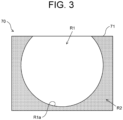
- FIG. 3 shows an example of each display area on the display screen of the display unit 71.
- the display unit 71 has an image display area R1 and an alarm information display area R2.
- the display of information in the image display area R1 and the alarm information display area R2 of the display unit 71 is controlled by the controller 60.
- the image display area R1 is the area where the image obtained by the monitoring unit 50 is displayed.
- the "image obtained by the monitoring unit 50" indicates the overhead image Bv (see FIG. 4 ) generated by the overhead image generation unit 53 of the monitoring unit 50, for example.
- the alarm information display area R2 is the area where alarm information W (see FIG. 4 ) indicating the presence of the obstacle is displayed when the monitoring unit 50 detects that the obstacle is present.
- the display unit 71 has the image display area R1 for displaying an image obtained by the monitoring unit 50 and the alarm information display area R2 for displaying the alarm information W indicating the presence of the obstacle when the monitoring unit 50 detects that the obstacle is present.
- the alarm information display area R2 is located outside the image display area R1 in the display unit 71. Furthermore, the alarm information display area R2 is located adjacent to the image display area R1 in the display unit 71.
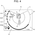
- FIG. 4 shows the display unit 71 in which the overhead image Bv is displayed in the image display area R1 and the alarm information W is displayed in the alarm information display area R2.
- the overhead image Bv displayed in the image display area R1 includes images T1-T3 of humans imaged in the image as obstacles.
- the image display area R1 also displays a vehicle image S showing the hydraulic excavator 1. Accordingly, the display unit 71 displays the overhead image Bv together with a vehicle image S which shows the hydraulic excavator 1 in the image display area R1.
- the alarm information W displayed in the alarm information display area R2 includes strip-shaped information P, direction information A, and type information M.
- the strip-shaped information P is information that is displayed in a strip shape along a circumferential edge R1a (see FIG. 3 ) of the image display area R1.
- humans see T1 and T2 are imaged in the overhead image Bv, which is displayed in the image display area R1, on the left side of the hydraulic excavator 1, so that in the alarm information display area R2, the strip-shaped information P1 is displayed at a position corresponding to the humans on the left side of the hydraulic excavator 1 in an arc shape along the circumferential edge R1a of the image display area R1.
- the alarm information W includes the strip-shaped information P (P1, P2) that is displayed in a strip shape along the circumferential edge R1a of the image display area R1.
- the "position corresponding to something on the left side of the hydraulic excavator 1 in the alarm information display area R2" only has to be any position where the operator can recognize that the display position of the strip-shaped information P1 in the alarm information display area R2 is "on the left of the vehicle image S showing the hydraulic excavator 1," and the direction may not be limited to the strictly left side.
- a position corresponding to something on the left side includes positions on the diagonally forward left or diagonally backward left side in addition to the strictly left side.
- positions corresponding to something on the rear side include positions on the diagonally left rear or diagonally right rear side in addition to the strictly rear side
- positions corresponding to something on the right side include positions on the diagonally forward right or diagonally backward right side in addition to the strictly right side.
- the direction information A is information indicating the direction of obstacles imaged in the image (e.g., overhead image Bv) as viewed from the hydraulic excavator 1.
- the humans are imaged in the overhead image Bv on the left side of the hydraulic excavator 1, so that an icon of a left arrow is displayed as direction information A1 at a position corresponding to the humans on the left side of the hydraulic excavator 1 in the alarm information display area R2.
- another human is also imaged in the overhead image Bv behind the hydraulic excavator 1, so that an icon of a back arrow is displayed as direction information A2 at a position corresponding to the human on the rear side of the hydraulic excavator 1 in the alarm information display area R2.
- the alarm information W includes the direction information A indicating the direction of the obstacle imaged in the image obtained by the monitoring unit 50, relative to the hydraulic excavator 1.
- the type information M is information indicating the type of obstacle detected by the image processor 53 of the monitoring unit 50. If the image processor 53 detects "humans" of being obstacles on the left side of the hydraulic excavator 1 by performing the image processing, an icon indicating that the detected obstacles are “humans” is displayed as type information M1 at a position corresponding to the humans on the left side of the hydraulic excavator 1 in the alarm information display area R2. If the image processor 53 detects a "human” of being an obstacle behind the hydraulic excavator 1 by performing the image processing, an icon indicating that the detected obstacle is a "human” is displayed as type information M2 in a position corresponding to the human on the rear side of the hydraulic excavator 1 in the alarm information display area R2. Thus, the alarm information W includes the type information M indicating the type of the obstacle detected by the image processor 53.
- the display unit 71 displays the alarm information W as follows. Namely, if the monitoring unit 50 detects the presence of an obstacle, the display unit 71 displays the alarm information W at a position corresponding to the obstacle imaged in the image in a direction viewed from the hydraulic excavator 1 in the alarm information display area R2.
- the monitoring unit 50 monitors the state around the hydraulic excavator 1 in multiple monitoring segments D1 and D2, as described above. Therefore, if the monitoring unit 50 detects the presence of the obstacle, the display unit 71 displays the alarm information W in a color corresponding to the monitoring segment in which the obstacle is present. For example, if the monitoring unit 50 detects the obstacle in the monitoring segment D1 (a range of less than 2m radius from the hydraulic excavator 1), the display unit 71 displays the alarm information W in red, for example. On the other hand, if the monitoring unit 50 detects an obstacle in the monitoring segment D2 (a range of from 2m to 3m radius from the hydraulic excavator 1), the display unit 71 displays the alarm information W in yellow, for example.
- the monitoring unit 50 detects the obstacle in the monitoring segment D1, which has a high risk of contact between the obstacle and the hydraulic excavator 1, among the monitoring segments D1 and D2 set in advance, red color is adopted to the alarm information W.
- the monitoring unit 50 detects the obstacle in the monitoring segment D2 in which the risk of contact between the obstacle and the hydraulic excavator 1 is not high, from among the monitoring segments D1 and D2, but an attention should be paid, yellow color is adopted to the alarm information W.
- the strip-shaped information P1, direction information A1 and type information M1 as the alarm information W are displayed in yellow. Furthermore, if a "human” of being an obstacle is detected in the monitoring segment D1 behind the hydraulic excavator 1, the strip-shaped information P2, direction information A2 and type information M2 as the alarm information W are displayed in red.
- the alarm information W colored in yellow is indicated by a dashed line
- the alarm information W colored in red is indicated by a solid line.
- the alarm information display area R2 is located outside the image display area R1 in the display unit 71. Therefore, even if the obstacles imaged in the image (e.g., overhead image Bv) displayed in the image display area R1 are very small compared to the entire image, the alarm information W indicating the presence of the obstacles can be displayed relatively large in the alarm information display area R2 with being clearly distinguished from the image mentioned above.
- the strip-shaped information P1 in the alarm information W can be displayed larger (wider) than images T1 and T2 in the alarm information display area R2.
- the strip-shaped information P2 in the alarm information W can be displayed larger (wider) than the image T3.
- Such a display of the alarm information W makes it easy for the operator to intuitively know the presence of obstacles around the hydraulic excavator 1. As a result, it is possible for the operator to easily know danger such as collision between the hydraulic excavator 1 and pay attention thereto.
- the display unit 71 is configured such that the alarm information display area R2 is adjacent to the image display area R1, a distance between the alarm information display area R2 and the image display area R1 is small. This makes it easier for the operator to check the image displayed in the image display area R1 to confirm the presence of obstacles immediately after seeing the alarm information W when the alarm information W is displayed in the alarm information display area R2.
- the display unit 71 displays the alarm information W at a position corresponding to the obstacle imaged in the image (e.g., the overhead image Bv) in a direction viewed from the hydraulic excavator 1 in the alarm information display area R2.
- This allows the operator to easily and intuitively know the direction of the obstacles viewed from the hydraulic excavator 1 based on the display position of the alarm information W in the alarm information display area R2.
- the operator can easily and intuitively know that the direction of the obstacles is on the left side of the hydraulic excavator 1 based on the display position of the strip-shaped information P1, direction information A1, and type information M1 as the alarm information W.
- the operator can easily and intuitively know that the direction of the obstacle is behind the hydraulic excavator 1 based on the display position of the strip-shaped information P2, direction information A2, and type information M2 as the alarm information W.
- the strip-shaped information P is displayed as a strip shape along the circumferential edge R1a of the image display area R1, it is easy for the operator to see and know it. Therefore, since the alarm information W includes the strip-shaped information P, this makes it easier for the operator to know the presence of obstacles based on the strip-shaped information P.
- the alarm information W includes the direction information A. This allows the operator to easily and intuitively know the direction of the obstacles relative to the hydraulic excavator 1 upon seeing the direction information A displayed. For example, in the example shown in FIG. 4 , the operator can easily and intuitively know the direction of the obstacles is on the left side of the hydraulic excavator 1 upon seeing the direction information A1 as the alarm information W. Furthermore, the operator can easily and intuitively know that the direction of the obstacle is behind the hydraulic excavator 1 upon seeing the direction information A2 as the alarm information W.
- the display unit 71 displays the alarm information W in colors corresponding to the monitoring segments D1 and D2 in which the obstacle is present. By seeing the color of the alarm information W displayed, the operator can immediately determine which monitoring segment the obstacle detected by the monitoring unit 50 belongs to. The operator can then intuitively know whether the obstacle is close to the hydraulic excavator 1 or not, and easily know the degree of danger.
- the monitoring unit 50 has the image capturing unit 51 and the image processor 52.
- the image processor 52 detects whether or not the obstacle is present around the hydraulic excavator 1 by performing image recognition processing on the images captured by the image capturing unit 51.
- the monitoring unit 50 to monitor the state around the hydraulic excavator 1 can be realized without obstacle sensors. Namely, it is possible to realize the monitoring unit 50 simply configured without obstacle sensors.
- the alarm information W includes the type information M. This allows the operator to easily know the type of obstacle (e.g., human/animal/other) present around the hydraulic excavator 1 upon seeing the type information M displayed.
- the type of obstacle e.g., human/animal/other
- the display unit 71 displays an overhead image Bv together with a vehicle image S showing the hydraulic excavator 1. In this case, by viewing both the vehicle image S and the overhead image Bv, the operator can easily know the position of the obstacle relative to the hydraulic excavator 1 when it appears in the overhead image Bv.
- FIG. 5 is an explanatory diagram illustrating another example of each display area on the display screen of the display unit 71.
- the image display area R1 of the display unit 71 may include a plurality of image display areas R1-1 to R1-3.
- the image display areas R1-1 to R1-3 display images obtained by the monitoring unit 50.
- the image display areas R1-1 to R1-3 display the camera images Cv-1 to Cv-3 (see FIG. 6 ), which are captured by the left camera 51a, right camera 51b, and rear camera 51c constituting the image capturing unit 51 of the monitoring unit 50, respectively.
- the display unit 71 has the same configuration as the example shown in FIGS. 3 and 4 in that the alarm information display area R2 is located outside the image display area R1 (R1-1 to R1-3) and that the alarm information display area R2 is located adjacent to the image display area R1 (R1-1 to R1-3), etc.
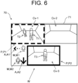
- FIG. 6 is an explanatory diagram illustrating another display example of the display unit 71.
- the display unit 71 can display the alarm information W (strip-shaped information P1, direction information A1, and type information M1) at a position (e.g., in the vicinity of the image display area R1-1) corresponding to the obstacles imaged in the camera image Cv-1 in a direction viewed from the hydraulic excavator 1 in the alarm information display area R2.
- the alarm information W strip-shaped information P1, direction information A1, and type information M1
- the display unit 71 can display the alarm information W (strip-shaped information P2, direction information A2, and type information M2) at a position (e.g., in the vicinity of the image display area R1-3) corresponding to the obstacle imaged in the camera image Cv-3 in a direction viewed from the hydraulic excavator 1 in the alarm information display area R2.
- the alarm information W strip-shaped information P2, direction information A2, and type information M2
- the strip-shaped information P (P1, P2) as the alarm information is displayed in a frame shape surrounding the entire boundary of the camera images Cv-1 and Cv-3.
- the correspondence between the camera images Cv-1 and Cv-3 and the strip-shaped information P1 and P2 is clear, so that the operator can easily know the direction of the obstacle viewed from the hydraulic excavator 1 upon seeing the alarm information W (strip-shaped information P1 and P2).
- the strip-shaped information P may be displayed as a strip shape along only a portion of the boundary of the camera image Cv-1, etc.
- the hydraulic excavator 1 which is the construction machine is described as an example of the work vehicle, but the work vehicle is not limited to the hydraulic excavator, and may be any other construction machine such as wheel loader, or an agricultural machine such as combine harvester.
- the display method of the display unit 71 described in the present embodiment can be applied to any construction equipment and agricultural machinery other than the hydraulic excavator 1.
- the present invention is applicable to a work vehicle such as a construction machine and an agricultural machine, for example.
Landscapes
- Engineering & Computer Science (AREA)
- Mining & Mineral Resources (AREA)
- Civil Engineering (AREA)
- General Engineering & Computer Science (AREA)
- Structural Engineering (AREA)
- Physics & Mathematics (AREA)
- General Physics & Mathematics (AREA)
- Theoretical Computer Science (AREA)
- Computer Vision & Pattern Recognition (AREA)
- Multimedia (AREA)
- Signal Processing (AREA)
- Component Parts Of Construction Machinery (AREA)
- Closed-Circuit Television Systems (AREA)
- Image Analysis (AREA)
Abstract
Description
- The present invention relates to a work vehicle.
- Various monitoring systems have been proposed to monitor a state around a work vehicle such as an excavator. For example,
Patent Literature 1 discloses a system which captures images of a state around the excavator, displays the captured images on a display, as well as highlights the areas of people in the above mentioned images by surrounding them with a frame line. - Patent Literature 1:
Japanese Patent Laid-open Publication No. 2017-101420 - However, in a configuration where the captured image and the frame line are superimposed and displayed on the display unit, as disclosed in
Patent Literature 1, it is difficult to see because multiple pieces of information are superimposed. In addition, if the human in the image is very small compared to the entire image, the frame line surrounding the human in the image is much smaller than the entire image. This makes it difficult for the operator (driver) of the work vehicle to intuitively detect the presence of an obstacle around the work vehicle by looking at the display. As a result, it is difficult for the operator to detect hazard such as collision between the work vehicle and the obstacle. - The present invention has been made to solve the above mentioned problem, and an object of the present invention is to provide a work vehicle capable of easily letting an operator of the work vehicle intuitively know the presence of an obstacle around the work vehicle when looking at the display, thereby easily letting the operator know danger such as a collision between the work vehicle and the obstacle.
- According to one aspect of the present invention, a work vehicle is provided, which includes: a monitoring unit that captures an image around the work vehicle and detects whether or not an obstacle is present around the work vehicle, thereby to monitor a state around the work vehicle; and a display unit to display the image obtained by the monitoring unit, wherein the display unit has: an image display area that displays the image; and an alarm information display area that displays alarm information indicating a presence of the obstacle when the monitoring unit detects that the obstacle is present, the alarm information display area is located outside the image display area in the display unit.
- According to the above configuration, in the display unit, the alarm information display area is located outside the image display area, so that the alarm information indicating the presence of the obstacle can be clearly and largely displayed outside the image display area. This makes it easy for the operator of a work vehicle looking at the display to intuitively and easily know the presence of the obstacle around the work vehicle, and makes it easy for the operator to know danger such as a collision between the work vehicle and an obstacle.
-
-
FIG. 1 is a side view illustrating a schematic configuration of a hydraulic excavator which is an example of a work vehicle according to an embodiment of the present invention. -
FIG. 2 is an explanatory diagram illustrating a configuration of a main part of the hydraulic excavator. -
FIG. 3 is an explanatory diagram illustrating an example of each display area on a display screen of a display unit of the hydraulic excavator. -
FIG. 4 is an explanatory diagram illustrating a display example of the display unit. -
FIG. 5 is an explanatory diagram illustrating another example of each display area on the display screen of the display unit. -
FIG. 6 is an explanatory diagram illustrating another display example of the display unit. - Now, an embodiment of the present invention is described below with reference to the drawings.
-
FIG. 1 is a side view showing a schematic configuration of ahydraulic excavator 1 which is an example of a work vehicle according to the present embodiment. Thehydraulic excavator 1 includes alower traveling body 2, awork machine 3, and an upper revolvingbody 4. - Here, in
FIG. 1 , directions are defined as follows. First, the direction in which the lowertraveling body 2 travels straight ahead is defined as a front-rear direction, one and other sides thereof are defined as "front" and "rear", respectively. InFIG. 1 , ablade 23 side with respect to a travelingmotor 22 is exemplarily shown as "front". In addition, a horizontal direction perpendicular to the front-rear direction is defined as a left-right direction. In this instance, as viewed from an operator sitting at an operator'sseat 41a, left and right sides are defined as "left" and "right", respectively. Furthermore, a direction of gravity perpendicular to the front-rear and left-right directions is defined as a vertical direction, and upstream and downstream sides of the direction of gravity are defined as "up" and "down", respectively. - The lower traveling
body 2 is driven by power from anengine 40 to cause thehydraulic excavator 1 to travel. The lower travelingbody 2 is equipped with a pair ofcrawlers 21 on each side and a pair oftraveling motors 22 on each side. Each of thetraveling motors 22 is a hydraulic motor. Thetraveling motors 22 on each side drive thecrawlers 21 on each side, respectively, and it allows thehydraulic excavator 1 to move forward and backward. The lower travelingbody 2 is provided with theblade 23 for performing ground leveling work, and ablade cylinder 23a. Theblade cylinder 23a is a hydraulic cylinder to rotate theblade 23 in the vertical direction. - The
work machine 3 is driven by power from anengine 40 and performs excavation work to dig out earth and sand. Thework machine 3 has aboom 31, anarm 32, and abucket 33. Theboom 31,arm 32, andbucket 33 can be driven independently to perform digging operations. - The
boom 31 is rotated by aboom cylinder 31a. Abase end portion of theboom cylinder 31a is supported by a front portion of the upper revolvingbody 4 and the boom cylinder can move in a freely extendable manner. Thearm 32 is rotated by anarm cylinder 32a. A base end portion of thearm cylinder 32a is supported by a tip of theboom 31 and the arm cylinder can move in a freely extendable manner. Thebucket 33 is rotated by abucket cylinder 33a. A base end portion of thebucket cylinder 33a is supported by a tip of thearm 32 and the bucket cylinder can move in a freely extendable manner. Each of theboom cylinder 31a, thearm cylinder 32a, and thebucket cylinder 33a is composed of a hydraulic cylinder. - The
bucket 33 is a container-like component with claws for digging, located at the tip of thework machine 3. Thebucket 33 is pivotably attached to the tip of thearm 32 via apin 34. In addition, thebucket 33 is connected to thebucket cylinder 33a via alink mechanism 35. - A
hook 36 for crane work is attached to the tip ofarm 32. Thehook 36 is a hook-shaped member for the crane work and is pivotably attached to thelink mechanism 35. Here, the crane work refers to lifting work in which an object to be worked is lifted up or down. Thehook 36 is pivotably supported by the shaft of thelink mechanism 35 as a turning fulcrum, and can change its posture between an extending state (seeFIG. 1 ) where the hook extends from thebucket 33 and a retracting state (not shown) where the hook retracts to thebucket 33 side. For example, when performing excavation work with thebucket 33, thehook 36 comes to be in the retracting state. On the other hand, when performing the crane work with thehook 36, thehook 36 comes to be in the extending state. - The upper revolving
body 4 is configured to be revolvable relative to the lower travelingbody 2 via a swing bearing (not shown). Anoperation section 41, a revolving table 42, a revolvingmotor 43, anengine room 44, etc. are arranged in the upper revolvingbody 4. The upper revolvingbody 4 is driven by the revolvingmotor 43 which is a hydraulic motor to revolve via the swing bearing. At the rear portion of the upper revolvingbody 4, there are arranged a plurality of hydraulic pumps P0 (seeFIG. 2 ), as well as theengine 40 to provide power to various parts. - Each of the hydraulic pumps P0 supplies hydraulic oil (pressure oil) to a hydraulic motor (e.g., right and left traveling
motors 22 and the revolving motor 43) and a hydraulic cylinder (e.g., theblade cylinder 23a, theboom cylinder 31a, thearm cylinder 32a, thebucket cylinder 33a). The hydraulic motor and the hydraulic cylinder, which are driven with the hydraulic oil supplied from any of the hydraulic pumps P0, are collectively referred to as a hydraulic actuator AC (seeFIG. 2 ). - An operator's
seat 41a on which the operator rides is located in theoperation section 41. Amanipulation unit 41b is placed around the operator'sseat 41a (especially forward, left and right side). - The
manipulation unit 41b consists of an operation lever, a switch, a button, etc. to drive the hydraulic actuator AC. Sitting on the operator'sseat 41a and operating themanipulation unit 41b, the operator can actuate the hydraulic actuator AC. This allows the operator to perform the traveling of thelower traveling body 2, the ground leveling work by theblade 23, the excavation work and crane work by thework machine 3, and the revolving of the upper revolvingbody 4, etc. -
FIG. 2 schematically shows a configuration of a main part of thehydraulic excavator 1. Thehydraulic excavator 1 further includes amonitoring unit 50, acontroller 60, amonitor 70, a rotary lamp 81, a light emitter 82, and a sounding unit 83. - The
monitoring unit 50 detects whether or not an obstacle is present around thehydraulic excavator 1, thereby to monitor a state therearound. The obstacle may include an object to be monitored, such as a human, an object, or an animal. Namely, thehydraulic excavator 1 is provided with themonitoring unit 50 to monitor the state around thehydraulic excavator 1. In the present embodiment, themonitoring unit 50 captures an image around thehydraulic excavator 1 and detects whether or not the obstacle is present around thehydraulic excavator 1, thereby to monitor the state around thehydraulic excavator 1. Explained more specifically, themonitoring unit 50 has the following configuration. - The
monitoring unit 50 has animage capturing unit 51, an image processor 52, and an overhead image generation unit 53. Theimage capturing unit 51 includes a right camera 51a, aleft camera 51b, and arear camera 51c, which capture images of a right side, left side, and rear of thehydraulic excavator 1, respectively. In other words, themonitoring unit 50 has theimage capturing unit 51 to capture the images. Furthermore, theimage capturing unit 51 includes a plurality of cameras (right camera 51a,left camera 51b, andrear camera 51c) which capture images around thehydraulic excavator 1. Theimage capturing unit 51 captures a moving image, for example, but it may capture a still image at a predetermined frame cycle. - The image processor 52 performs image recognition processing on an image (e.g., a right side image) captured by the
image capturing unit 51 as an input, thereby to detect whether an object in the above mentioned image is an obstacle and a type of the obstacle (human/object/animal) and detect objects invading into a monitoring area. Namely, themonitoring unit 50 has an image processor 52 to detect whether or not the obstacles is present around thehydraulic excavator 1 by performing the image recognition processing on the images captured by theimage capturing unit 51. The image processor 52 further detects the type of obstacle by means of the above mentioned image recognition processing. - The overhead image generation unit 53 generates an overhead image (bird's-eye view image) centering around the
hydraulic excavator 1 by performing the image processing on a plurality of images captured by a plurality of cameras (right camera 51a,left camera 51b,rear camera 51c) of theimage capturing unit 51. Namely, themonitoring unit 50 has the overhead image generation unit 53 to generate the overhead image by performing the image processing on the plurality of images captured by the plurality of cameras. - The image processor 52 and the overhead image generation unit 53 described above consist of a central processing unit called a CPU (Central Processing Unit) or a computing device such as a GPU (Graphics Processing Unit), for example.
- As long as the obstacle can be detected by the
monitoring unit 50 within a given range, the number of cameras, an installation location, and an installation method are not particularly limited. The system may also be configured to detect obstacles using an obstacle sensor instead of a camera. As the obstacle sensor, any known distance measuring device capable of acquiring distance information of the obstacle can be applied. For example, an ultrasonic radar using ultrasonic waves, a millimeter wave radar using millimeter wave band radio waves, a LIDER that measures a scattered light in response to laser radiation thereby to calculate a distance, and a stereo camera which is provided with plural cameras and measures the distance from a taken image to an object can be used as the obstacle sensor. When an obstacle sensor is used, the position information of an obstacle can be obtained based on the phase difference information of the light emission/reception timing when the light is emitted, and the presence of an obstacle can be determined based on the light intensity information when the light is received. - The
monitoring unit 50 also monitors a state around thehydraulic excavator 1 in a plurality of monitoring segments which are segmented according to each distance from thehydraulic excavator 1. For example, the image processor 52 can detect obstacles based on the above mentioned images and obtain the distance of the obstacle from thehydraulic excavator 1 by means of the image processing. If the monitoring range around thehydraulic excavator 1 is divided into two monitoring segments, D1 and D2, where D1 is a monitoring segment having a radius of less than 2m centering around thehydraulic excavator 1 and D2 is a monitoring segment having a radius from 2m to 3m, the image processor 52 can determine which of the two monitoring segments, D1 and D2, the detected obstacle belongs to based on the distance of the obstacle from thehydraulic excavator 1. Namely, themonitoring unit 50 can monitor whether or not obstacles are present in the multiple monitoring segments D1 and D2. Themonitoring unit 50 may obtain the distance of the obstacle from thehydraulic excavator 1 by the obstacle sensor described above, and determine which of the two monitoring segments, D1 and D2, the detected obstacle belongs to. - The
controller 60 controls operation of each part of thehydraulic excavator 1. Such thecontroller 60 is configured as an electronic control unit referred as to an ECU (Electronic Control Unit). Thecontroller 60 may include a storage unit. The storage unit stores a program and various information to run thecontroller 60. A RAM (Random Access Memory), a ROM (Read Only Memory), and the like can be used as the storage unit mentioned above. - The
monitor 70 is located in the vicinity of (e.g., diagonally forward of) the operator'sseat 41a and displays various types of information to provide necessary information to the operator sitting on the operator'sseat 41a. Themonitor 70 has adisplay unit 71 and aninput 72. Themonitor 70 itself may have an ECU (monitor ECU) inside, and it may be configured so that the monitor ECU controls each part of themonitor 70. - The
display unit 71 consists of a liquid crystal display device to display various types of information, for example. For example, thedisplay unit 71 displays an image obtained by themonitoring unit 50. Namely, thehydraulic excavator 1 includes adisplay unit 71 to display the image obtained by themonitoring unit 50. Thedisplay unit 71 also displays alarm information indicating the presence of an obstacle when themonitoring unit 50 detects that the obstacle is present around thehydraulic excavator 1. A display screen of thedisplay unit 71 is described in more detail below. - The operator can operate the
input 72 to set and input various types of information. Theinput 72 consists of a touch panel input device which is superimposed on thedisplay unit 71, for example. Theinput 72 may consist of mechanical input buttons or a jog dial. The display screen of thedisplay unit 71 can also be switched (e.g., between a screen shown inFIG. 4 and a screen shown inFIG. 6 ) by the operator operating the input 72 (e.g., pressing a predetermined position). - A rotary lamp 81 shown in
FIG. 2 consists of a lamp which rotates when themonitoring unit 50 detects the obstacle. Alight emitter 82 consists of, for example, a light-emitting diode (LED) which lights up or blinks when themonitoring unit 50 detects the obstacle. A sounding unit 83 consists of a buzzer which makes a sound when themonitoring unit 50 detects the obstacle. The sounding unit 83 may consist of an audio output unit which outputs voice (electronic sound) when themonitoring unit 50 detects the obstacle. The rotation of the rotary lamp 81, the lighting up (or blinking) of the light emitter 82, and the output of a buzzer sound or voice of the sounding unit 63 allow the operator to recognize that themonitoring unit 50 detects the obstacle. - As described above, the
display unit 71 of themonitor 70, the rotary lamp 81, the light emitter 82, and the sounding unit 83 issues an alarm by displaying an icon or the like, rotating a lamp, emitting light, or making a sound, respectively, when themonitoring unit 50 detects the obstacle. Accordingly, it can be said that thedisplay unit 71, the rotary lamp 81, the light emitter 82, and the sounding unit 83 constitute an alarm device 90 which issues an alarm based on the monitoring result of themonitoring unit 50. Namely, thehydraulic excavator 1 includes the alarm device 90 which issues an alarm based on the monitoring result of themonitoring unit 50. The alarm device 90 only has to include at least one of thedisplay unit 71, the rotary lamp 81, the light emitter 82, and the sounding unit 83, not necessarily all of them. - Next, a hydraulic circuit of the
hydraulic excavator 1 is described with reference toFIGS. 1 and2 . Thehydraulic excavator 1 includes a plurality of hydraulic actuators AC, a hydraulic pump P0 which pumps pressure oil to the plurality of hydraulic actuators AC, and a pilot pump PP. For the convenience of explanation,FIG. 2 shows a hydraulic circuit corresponding to one hydraulic actuator AC, but a similar hydraulic circuit is configured for another hydraulic actuator AC. - The plurality of hydraulic actuators AC consists of right and left traveling
motors 22 which are hydraulic actuators for traveling to drive thelower traveling body 2, theblade cylinder 23a which is a hydraulic actuator to rotate theblade 23 vertically, the revolvingmotor 43 which is a hydraulic actuator for revolving to drive the upper revolvingbody 4, and theboom cylinder 31a,arm cylinder 32a andbucket cylinder 33a each of which is a hydraulic actuator for work to drive thework machine 3. Theblade cylinder 23a, theboom cylinder 31a, thearm cylinder 32a, and thebucket cylinder 33a are collectively referred to as a hydraulic cylinder CY - The
hydraulic excavator 1 may be configured so as to have a so-called boom swing function which swings the work machine 3 (boom 31) in a right-left direction relative to the upper revolvingbody 4. When thehydraulic excavator 1 has the boom swing function, the hydraulic cylinder CY also includes a swing cylinder which is a hydraulic actuator to swing theboom 31. In general, the boom swing function is applied to a mini excavator (small hydraulic excavator) used for construction in a narrow place. - The plurality of hydraulic pumps P0 consist of a variable displacement pump and a fixed displacement pump, and is driven by the
engine 40. The variable displacement pump pumps the pressure oil to the right and left travelingmotors 22, theboom cylinder 31a, thearm cylinder 32a and thebucket cylinder 33a. The fixed displacement pump supplies the pressure oil to theblade cylinder 23a, the revolvingmotor 43, and a swing cylinder (not shown). - Each of the plurality of actuators AC is provided with a corresponding direction switching valve CV The direction switching valve CV is a pilot-type direction switching valve to switch the direction and flow rate of the pressure oil pumped from the hydraulic pump P0 (variable displacement pump or fixed displacement pump), also called a control valve. The direction switching valve CV according to the present embodiment include, for example, a direction switching valve corresponding to the right and left traveling
motors 22, a direction switching valve corresponding to theboom cylinder 31a, a direction switching valve corresponding to thearm cylinder 32a, a direction switching valve corresponding to thebucket cylinder 33a, a direction switching valve corresponding to theblade cylinder 23a, a direction switching valve corresponding to the revolvingmotor 43, and a direction switching valve corresponding to the swing cylinder. - The pilot pump PP discharges pilot oil which serves as an input order to the direction switching valve CV The pilot pump PP driven by the
engine 40 discharges the pressure oil, thereby to generate pilot pressure in a pilot oil path. Thehydraulic excavator 1 is provided with the pilot oil paths leading to each of the direction switching valves CV from the pilot pump PP. - The
manipulation unit 41b has a remote control valve RV for switching the direction and pressure of the pressure oil supplied to the direction switching valve CV The pressure oil discharged from the pilot pump PP is supplied to the remote control valve RV. The remote control valve RV generates the pilot pressure according to the operating direction and operating amount of themanipulation unit 41b. Themanipulation unit 41b includes a traveling lever to cause thehydraulic excavator 1 to travel and an operation lever to operate thework machine 3, for example. - A solenoid valve SV is provided in the oil path between the pilot pump PP and each remote control valve RV. In response to instructions for control from the
controller 60, the solenoid valve SV adjusts the pilot pressure generated by the pilot pump PP. Adjusting the pilot pressure allows the plural hydraulic actuators AC to simultaneously stop the driving thereof as well as to uniformly control the drive speeds thereof, for example. - Next, a display screen of the
display unit 71 mentioned above is described in detail.FIG. 3 shows an example of each display area on the display screen of thedisplay unit 71. Thedisplay unit 71 has an image display area R1 and an alarm information display area R2. The display of information in the image display area R1 and the alarm information display area R2 of thedisplay unit 71 is controlled by thecontroller 60. - The image display area R1 is the area where the image obtained by the
monitoring unit 50 is displayed. The "image obtained by themonitoring unit 50" indicates the overhead image Bv (seeFIG. 4 ) generated by the overhead image generation unit 53 of themonitoring unit 50, for example. The alarm information display area R2 is the area where alarm information W (seeFIG. 4 ) indicating the presence of the obstacle is displayed when themonitoring unit 50 detects that the obstacle is present. - Namely, the
display unit 71 has the image display area R1 for displaying an image obtained by themonitoring unit 50 and the alarm information display area R2 for displaying the alarm information W indicating the presence of the obstacle when themonitoring unit 50 detects that the obstacle is present. - In the present embodiment, the alarm information display area R2 is located outside the image display area R1 in the
display unit 71. Furthermore, the alarm information display area R2 is located adjacent to the image display area R1 in thedisplay unit 71. -
FIG. 4 shows thedisplay unit 71 in which the overhead image Bv is displayed in the image display area R1 and the alarm information W is displayed in the alarm information display area R2. The overhead image Bv displayed in the image display area R1 includes images T1-T3 of humans imaged in the image as obstacles. The image display area R1 also displays a vehicle image S showing thehydraulic excavator 1. Accordingly, thedisplay unit 71 displays the overhead image Bv together with a vehicle image S which shows thehydraulic excavator 1 in the image display area R1. - The alarm information W displayed in the alarm information display area R2 includes strip-shaped information P, direction information A, and type information M.
- The strip-shaped information P is information that is displayed in a strip shape along a circumferential edge R1a (see
FIG. 3 ) of the image display area R1. As shown inFIG. 4 , humans (see T1 and T2) are imaged in the overhead image Bv, which is displayed in the image display area R1, on the left side of thehydraulic excavator 1, so that in the alarm information display area R2, the strip-shaped information P1 is displayed at a position corresponding to the humans on the left side of thehydraulic excavator 1 in an arc shape along the circumferential edge R1a of the image display area R1. In addition, another human (see T3) is also imaged in the overhead image Bv at a position behind thehydraulic excavator 1, so that in the alarm information display area R2, the strip-shaped information P2 is displayed at a position corresponding to the human behind thehydraulic excavator 1 in an arc shape along the circumferential edge R1a of the image display area R1. Accordingly, the alarm information W includes the strip-shaped information P (P1, P2) that is displayed in a strip shape along the circumferential edge R1a of the image display area R1. - The "position corresponding to something on the left side of the
hydraulic excavator 1 in the alarm information display area R2" only has to be any position where the operator can recognize that the display position of the strip-shaped information P1 in the alarm information display area R2 is "on the left of the vehicle image S showing thehydraulic excavator 1," and the direction may not be limited to the strictly left side. For example, "a position corresponding to something on the left side" includes positions on the diagonally forward left or diagonally backward left side in addition to the strictly left side. Thus, in the following description, for example, it is assumed that "positions corresponding to something on the rear side" include positions on the diagonally left rear or diagonally right rear side in addition to the strictly rear side, and "positions corresponding to something on the right side" include positions on the diagonally forward right or diagonally backward right side in addition to the strictly right side. - The direction information A is information indicating the direction of obstacles imaged in the image (e.g., overhead image Bv) as viewed from the
hydraulic excavator 1. As shown inFIG. 4 , the humans are imaged in the overhead image Bv on the left side of thehydraulic excavator 1, so that an icon of a left arrow is displayed as direction information A1 at a position corresponding to the humans on the left side of thehydraulic excavator 1 in the alarm information display area R2. In addition, another human is also imaged in the overhead image Bv behind thehydraulic excavator 1, so that an icon of a back arrow is displayed as direction information A2 at a position corresponding to the human on the rear side of thehydraulic excavator 1 in the alarm information display area R2. Thus, the alarm information W includes the direction information A indicating the direction of the obstacle imaged in the image obtained by themonitoring unit 50, relative to thehydraulic excavator 1. - The type information M is information indicating the type of obstacle detected by the image processor 53 of the
monitoring unit 50. If the image processor 53 detects "humans" of being obstacles on the left side of thehydraulic excavator 1 by performing the image processing, an icon indicating that the detected obstacles are "humans" is displayed as type information M1 at a position corresponding to the humans on the left side of thehydraulic excavator 1 in the alarm information display area R2. If the image processor 53 detects a "human" of being an obstacle behind thehydraulic excavator 1 by performing the image processing, an icon indicating that the detected obstacle is a "human" is displayed as type information M2 in a position corresponding to the human on the rear side of thehydraulic excavator 1 in the alarm information display area R2. Thus, the alarm information W includes the type information M indicating the type of the obstacle detected by the image processor 53. - As described above, since the alarm information W is displayed at a position corresponding to an obstacle in a direction viewed from the
hydraulic excavator 1 in the alarm information display area R2, it can be said that thedisplay unit 71 displays the alarm information W as follows. Namely, if themonitoring unit 50 detects the presence of an obstacle, thedisplay unit 71 displays the alarm information W at a position corresponding to the obstacle imaged in the image in a direction viewed from thehydraulic excavator 1 in the alarm information display area R2. - In the present embodiment, the
monitoring unit 50 monitors the state around thehydraulic excavator 1 in multiple monitoring segments D1 and D2, as described above. Therefore, if themonitoring unit 50 detects the presence of the obstacle, thedisplay unit 71 displays the alarm information W in a color corresponding to the monitoring segment in which the obstacle is present. For example, if themonitoring unit 50 detects the obstacle in the monitoring segment D1 (a range of less than 2m radius from the hydraulic excavator 1), thedisplay unit 71 displays the alarm information W in red, for example. On the other hand, if themonitoring unit 50 detects an obstacle in the monitoring segment D2 (a range of from 2m to 3m radius from the hydraulic excavator 1), thedisplay unit 71 displays the alarm information W in yellow, for example. - Namely, if the
monitoring unit 50 detects the obstacle in the monitoring segment D1, which has a high risk of contact between the obstacle and thehydraulic excavator 1, among the monitoring segments D1 and D2 set in advance, red color is adopted to the alarm information W. On the other hand, if themonitoring unit 50 detects the obstacle in the monitoring segment D2 in which the risk of contact between the obstacle and thehydraulic excavator 1 is not high, from among the monitoring segments D1 and D2, but an attention should be paid, yellow color is adopted to the alarm information W. - As shown in
FIG. 4 , for example, if "humans" of being obstacles are detected in the monitoring segment D2 on the left side of thehydraulic excavator 1, the strip-shaped information P1, direction information A1 and type information M1 as the alarm information W are displayed in yellow. Furthermore, if a "human" of being an obstacle is detected in the monitoring segment D1 behind thehydraulic excavator 1, the strip-shaped information P2, direction information A2 and type information M2 as the alarm information W are displayed in red. For the convenience of explanation, inFIG. 4 , the alarm information W colored in yellow is indicated by a dashed line, and the alarm information W colored in red is indicated by a solid line. - In the present embodiment, as shown in
FIGS. 3 and4 , the alarm information display area R2 is located outside the image display area R1 in thedisplay unit 71. Therefore, even if the obstacles imaged in the image (e.g., overhead image Bv) displayed in the image display area R1 are very small compared to the entire image, the alarm information W indicating the presence of the obstacles can be displayed relatively large in the alarm information display area R2 with being clearly distinguished from the image mentioned above. For example, the strip-shaped information P1 in the alarm information W can be displayed larger (wider) than images T1 and T2 in the alarm information display area R2. Similarly, the strip-shaped information P2 in the alarm information W can be displayed larger (wider) than the image T3. Such a display of the alarm information W makes it easy for the operator to intuitively know the presence of obstacles around thehydraulic excavator 1. As a result, it is possible for the operator to easily know danger such as collision between thehydraulic excavator 1 and pay attention thereto. - Furthermore, in the present embodiment, since the
display unit 71 is configured such that the alarm information display area R2 is adjacent to the image display area R1, a distance between the alarm information display area R2 and the image display area R1 is small. This makes it easier for the operator to check the image displayed in the image display area R1 to confirm the presence of obstacles immediately after seeing the alarm information W when the alarm information W is displayed in the alarm information display area R2. - Furthermore, In the display area R2, the
display unit 71 displays the alarm information W at a position corresponding to the obstacle imaged in the image (e.g., the overhead image Bv) in a direction viewed from thehydraulic excavator 1 in the alarm information display area R2. This allows the operator to easily and intuitively know the direction of the obstacles viewed from thehydraulic excavator 1 based on the display position of the alarm information W in the alarm information display area R2. For example, in the example shown inFIG. 4 , the operator can easily and intuitively know that the direction of the obstacles is on the left side of thehydraulic excavator 1 based on the display position of the strip-shaped information P1, direction information A1, and type information M1 as the alarm information W. The operator can easily and intuitively know that the direction of the obstacle is behind thehydraulic excavator 1 based on the display position of the strip-shaped information P2, direction information A2, and type information M2 as the alarm information W. - In addition, since the strip-shaped information P is displayed as a strip shape along the circumferential edge R1a of the image display area R1, it is easy for the operator to see and know it. Therefore, since the alarm information W includes the strip-shaped information P, this makes it easier for the operator to know the presence of obstacles based on the strip-shaped information P.
- In addition, the alarm information W includes the direction information A. This allows the operator to easily and intuitively know the direction of the obstacles relative to the
hydraulic excavator 1 upon seeing the direction information A displayed. For example, in the example shown inFIG. 4 , the operator can easily and intuitively know the direction of the obstacles is on the left side of thehydraulic excavator 1 upon seeing the direction information A1 as the alarm information W. Furthermore, the operator can easily and intuitively know that the direction of the obstacle is behind thehydraulic excavator 1 upon seeing the direction information A2 as the alarm information W. - If the
monitoring unit 50 detects the presence of an obstacle, thedisplay unit 71 displays the alarm information W in colors corresponding to the monitoring segments D1 and D2 in which the obstacle is present. By seeing the color of the alarm information W displayed, the operator can immediately determine which monitoring segment the obstacle detected by themonitoring unit 50 belongs to. The operator can then intuitively know whether the obstacle is close to thehydraulic excavator 1 or not, and easily know the degree of danger. - The
monitoring unit 50 has theimage capturing unit 51 and the image processor 52. The image processor 52 detects whether or not the obstacle is present around thehydraulic excavator 1 by performing image recognition processing on the images captured by theimage capturing unit 51. Thus, themonitoring unit 50 to monitor the state around thehydraulic excavator 1 can be realized without obstacle sensors. Namely, it is possible to realize themonitoring unit 50 simply configured without obstacle sensors. - In addition, the alarm information W includes the type information M. This allows the operator to easily know the type of obstacle (e.g., human/animal/other) present around the
hydraulic excavator 1 upon seeing the type information M displayed. - In the image display area R1, the
display unit 71 displays an overhead image Bv together with a vehicle image S showing thehydraulic excavator 1. In this case, by viewing both the vehicle image S and the overhead image Bv, the operator can easily know the position of the obstacle relative to thehydraulic excavator 1 when it appears in the overhead image Bv. -
FIG. 5 is an explanatory diagram illustrating another example of each display area on the display screen of thedisplay unit 71. The image display area R1 of thedisplay unit 71 may include a plurality of image display areas R1-1 to R1-3. The image display areas R1-1 to R1-3 display images obtained by themonitoring unit 50. In more detail, the image display areas R1-1 to R1-3 display the camera images Cv-1 to Cv-3 (seeFIG. 6 ), which are captured by the left camera 51a,right camera 51b, andrear camera 51c constituting theimage capturing unit 51 of themonitoring unit 50, respectively. Thedisplay unit 71 has the same configuration as the example shown inFIGS. 3 and4 in that the alarm information display area R2 is located outside the image display area R1 (R1-1 to R1-3) and that the alarm information display area R2 is located adjacent to the image display area R1 (R1-1 to R1-3), etc. - Thus, even if the image display area R1 includes multiple image display areas R1-1 to R1-3, similar to the example shown in
FIG. 4 , thedisplay unit 71 can display the alarm information W at a predetermined location in the alarm information display area R2.FIG. 6 is an explanatory diagram illustrating another display example of thedisplay unit 71. If "humans" of being obstacles are imaged in the camera image Cv-1 captured by the left camera 51a and themonitoring unit 50 detects the obstacles, thedisplay unit 71 can display the alarm information W (strip-shaped information P1, direction information A1, and type information M1) at a position (e.g., in the vicinity of the image display area R1-1) corresponding to the obstacles imaged in the camera image Cv-1 in a direction viewed from thehydraulic excavator 1 in the alarm information display area R2. Similarly, if a "human" being of an obstacle is imaged in the camera image Cv-3 captured by therear camera 51c and themonitoring unit 50 detects the obstacle, thedisplay unit 71 can display the alarm information W (strip-shaped information P2, direction information A2, and type information M2) at a position (e.g., in the vicinity of the image display area R1-3) corresponding to the obstacle imaged in the camera image Cv-3 in a direction viewed from thehydraulic excavator 1 in the alarm information display area R2. - In
FIG. 6 , the strip-shaped information P (P1, P2) as the alarm information is displayed in a frame shape surrounding the entire boundary of the camera images Cv-1 and Cv-3. In this case, the correspondence between the camera images Cv-1 and Cv-3 and the strip-shaped information P1 and P2 is clear, so that the operator can easily know the direction of the obstacle viewed from thehydraulic excavator 1 upon seeing the alarm information W (strip-shaped information P1 and P2). The strip-shaped information P may be displayed as a strip shape along only a portion of the boundary of the camera image Cv-1, etc. - In the present embodiment, the
hydraulic excavator 1 which is the construction machine is described as an example of the work vehicle, but the work vehicle is not limited to the hydraulic excavator, and may be any other construction machine such as wheel loader, or an agricultural machine such as combine harvester. Namely, the display method of thedisplay unit 71 described in the present embodiment can be applied to any construction equipment and agricultural machinery other than thehydraulic excavator 1. - The embodiment of the present invention has been described above, but the scope of the invention is not limited thereto. The invention can be carried out within an extended or modified range without departing from the gist of the invention.
- The present invention is applicable to a work vehicle such as a construction machine and an agricultural machine, for example.
-
- 1 Hydraulic excavator (work vehicle)
- 50 Monitoring unit
- 51 Image capturing unit
- 51a Left camera (image capturing unit, camera)
- 51b Right camera (image capturing unit, camera)
- 51c Rear camera (image capturing unit, camera)
- 52 Image processor
- 53 Overhead image generation unit
- 71: Display unit
- Bv Overhead image
- Cv-1, Cv-2, Cv-3 Camera image
- A, A1, A2 Direction information
- M, M1, M2 Type Information
- P, P1, P2 Strip-shaped information
- D1, D2 Monitoring segment
- R1, R1-1, R1-2, R1-3 Image display area
- R2 Alarm information display area
- W Alarm information
Claims (9)
- A work vehicle comprising:a monitoring unit that captures an image around the work vehicle and detects whether or not an obstacle is present around the work vehicle, thereby to monitor a state around the work vehicle; anda display unit to display the image obtained by the monitoring unit,wherein the display unit includes:an image display area that displays the image; andan alarm information display area that displays alarm information indicating a presence of the obstacle when the monitoring unit detects that the obstacle is present,the alarm information display area is located outside the image display area in the display unit.
- The work vehicle according to claim 1, wherein
the alarm information display area is located adjacent to the image display area in the display unit. - The work vehicle according to claim 1 or 2, wherein
when the monitoring unit detects the presence of the obstacle, the display unit displays the alarm information at a position in the alarm information display area, corresponding to the obstacle imaged in the image in a direction relative to the work vehicle. - The work vehicle according to any one of claims 1 to 3, wherein
the alarm information includes strip-shaped information that is displayed in a strip-like shape along an edge of the image display area. - The work vehicle according to any one of claims 1 to 4, wherein
the alarm information includes direction information indicating the direction of the obstacle imaged in the image relative to the work vehicle. - The work vehicle according to any one of claims 1 to 5, whereinthe monitoring unit monitors the state around the work vehicle in a plurality of monitoring segments that are segmented according to a distance from the work vehicle, andwhen the monitoring unit detects the presence of the obstacle, the display unit displays the alarm information in a color corresponding to the monitoring segment in which the obstacle is present.
- The work vehicle according to any one of claims 1 to 6, wherein the monitoring unit includes:an image capturing unit to capture the image; andan image processor to detect whether or not the obstacle is present around the work vehicle by performing image recognition processing on the image captured by the image capturing unit.
- The work vehicle according to claim 7, whereinthe image processor further detects a type of the obstacle by means of the image recognition processing, andthe alarm information includes type information indicating the type of the obstacle detected by the image processor.
- The work vehicle according to claim 7 or 8, whereinthe image capturing unit includes a plurality of cameras to capture images around the work vehicle,the monitoring unit includesan overhead image generation unit to generate an overhead image by performing image processing on the images captured by the plurality of cameras, andthe display unit displays in the image display area the overhead image together with a vehicle image indicating the work vehicle.
Applications Claiming Priority (2)
| Application Number | Priority Date | Filing Date | Title |
|---|---|---|---|
| JP2020171621A JP7399836B2 (en) | 2020-10-12 | 2020-10-12 | work vehicle |
| PCT/JP2021/031938 WO2022080026A1 (en) | 2020-10-12 | 2021-08-31 | Work vehicle |
Publications (2)
| Publication Number | Publication Date |
|---|---|
| EP4227468A1 true EP4227468A1 (en) | 2023-08-16 |
| EP4227468A4 EP4227468A4 (en) | 2024-11-27 |
Family
ID=81208353
Family Applications (1)
| Application Number | Title | Priority Date | Filing Date |
|---|---|---|---|
| EP21879768.6A Pending EP4227468A4 (en) | 2020-10-12 | 2021-08-31 | WORK VEHICLE |
Country Status (6)
| Country | Link |
|---|---|
| US (1) | US20230407600A1 (en) |
| EP (1) | EP4227468A4 (en) |
| JP (3) | JP7399836B2 (en) |
| KR (1) | KR20230085909A (en) |
| CN (1) | CN116348910A (en) |
| WO (1) | WO2022080026A1 (en) |
Families Citing this family (5)
| Publication number | Priority date | Publication date | Assignee | Title |
|---|---|---|---|---|
| JP7201548B2 (en) * | 2019-07-12 | 2023-01-10 | 株式会社小松製作所 | working machine |
| JP7718810B2 (en) * | 2020-12-02 | 2025-08-05 | ヤンマーホールディングス株式会社 | Autonomous driving system, autonomous driving method, and autonomous driving program |
| JP2023176830A (en) * | 2022-06-01 | 2023-12-13 | ヤンマーホールディングス株式会社 | Work machine control method, work machine control program, work machine control system, and work machine |
| KR20250125794A (en) * | 2024-02-15 | 2025-08-22 | 에이치디현대인프라코어 주식회사 | Object detection system and method based on fusion of sensors and construction machine including the system |
| WO2025209651A1 (en) * | 2024-04-04 | 2025-10-09 | Stoneridge Electronics Ab | Camera monitor system with heads up display features |
Family Cites Families (17)
| Publication number | Priority date | Publication date | Assignee | Title |
|---|---|---|---|---|
| JP4776491B2 (en) * | 2006-10-06 | 2011-09-21 | 日立建機株式会社 | Work machine ambient monitoring device |
| JP4996928B2 (en) * | 2007-01-05 | 2012-08-08 | 日立建機株式会社 | Work machine ambient monitoring device |
| JP5227841B2 (en) | 2009-02-27 | 2013-07-03 | 日立建機株式会社 | Ambient monitoring device |
| JP2013146029A (en) | 2012-01-16 | 2013-07-25 | Toyota Motor Corp | Vehicle periphery monitoring device |
| JP6247450B2 (en) | 2013-03-31 | 2017-12-13 | 株式会社村上開明堂 | Driving assistance device |
| JP2015009646A (en) * | 2013-06-28 | 2015-01-19 | アルパイン株式会社 | Driving support device |
| JP6134668B2 (en) * | 2014-02-18 | 2017-05-24 | 日立建機株式会社 | Obstacle detection device for work vehicle |
| JP6262068B2 (en) * | 2014-04-25 | 2018-01-17 | 日立建機株式会社 | Near-body obstacle notification system |
| US9457718B2 (en) * | 2014-12-19 | 2016-10-04 | Caterpillar Inc. | Obstacle detection system |
| JP6262644B2 (en) | 2014-12-19 | 2018-01-17 | 日立建機株式会社 | Work machine ambient monitoring device |
| JP2017030688A (en) | 2015-08-06 | 2017-02-09 | 日立建機株式会社 | Work machine ambient monitoring device |
| JP2017046277A (en) | 2015-08-28 | 2017-03-02 | 日立建機株式会社 | Work machine ambient monitoring device |
| EP3385457A4 (en) * | 2015-11-30 | 2019-03-13 | Sumitomo Heavy Industries, Ltd. | PERIPHERAL SURVEILLANCE SYSTEM FOR CONSTRUCTION MACHINE |
| JP6419677B2 (en) | 2015-11-30 | 2018-11-07 | 住友重機械工業株式会社 | Perimeter monitoring system for work machines |
| JP7058569B2 (en) | 2018-07-19 | 2022-04-22 | 日立建機株式会社 | Work machine |
| JP7064066B2 (en) * | 2018-08-28 | 2022-05-10 | ヤンマーパワーテクノロジー株式会社 | Automatic driving system for work vehicles |
| JP7308089B2 (en) * | 2019-07-18 | 2023-07-13 | 株式会社小松製作所 | WORK VEHICLE DISPLAY SYSTEM AND WORK VEHICLE DISPLAY METHOD |
-
2020
- 2020-10-12 JP JP2020171621A patent/JP7399836B2/en active Active
-
2021
- 2021-08-31 US US18/031,005 patent/US20230407600A1/en active Pending
- 2021-08-31 KR KR1020237010740A patent/KR20230085909A/en active Pending
- 2021-08-31 CN CN202180069634.0A patent/CN116348910A/en active Pending
- 2021-08-31 EP EP21879768.6A patent/EP4227468A4/en active Pending
- 2021-08-31 WO PCT/JP2021/031938 patent/WO2022080026A1/en not_active Ceased
-
2023
- 2023-12-06 JP JP2023205875A patent/JP7591638B2/en active Active
-
2024
- 2024-11-18 JP JP2024201127A patent/JP7857378B2/en active Active
Also Published As
| Publication number | Publication date |
|---|---|
| WO2022080026A1 (en) | 2022-04-21 |
| JP2024015221A (en) | 2024-02-01 |
| JP2022063381A (en) | 2022-04-22 |
| JP2025015751A (en) | 2025-01-30 |
| CN116348910A (en) | 2023-06-27 |
| JP7857378B2 (en) | 2026-05-12 |
| JP7591638B2 (en) | 2024-11-28 |
| JP7399836B2 (en) | 2023-12-18 |
| EP4227468A4 (en) | 2024-11-27 |
| KR20230085909A (en) | 2023-06-14 |
| US20230407600A1 (en) | 2023-12-21 |
Similar Documents
| Publication | Publication Date | Title |
|---|---|---|
| US20230407600A1 (en) | Work Vehicle | |
| US20230407602A1 (en) | Work Vehicle | |
| EP3733982B1 (en) | Shovel and output device of shovel | |
| US12480284B2 (en) | Construction machine | |
| JP2023019920A (en) | WORKING MACHINE CONTROL METHOD, WORKING MACHINE CONTROL PROGRAM, WORKING MACHINE CONTROL SYSTEM, AND WORKING MACHINE | |
| JP2023047506A (en) | Control system for work machine, work machine, control method for work machine, and control program for work machine | |
| US20240392536A1 (en) | Work Machine Control Method, Work Machine Control Program, Work Machine Control System, And Work Machine | |
| US12441346B2 (en) | Work vehicle | |
| US20230392352A1 (en) | Work Machine Control Method, Work Machine Control Program, Work Machine Control System, And Work Machine | |
| KR20240002683A (en) | Control method of work machine, control program for work machine, control system for work machine, and work machine | |
| JP2025507643A (en) | Machine Safety Zone Control | |
| JP7763689B2 (en) | Work machine control system, work machine, work machine control method, and work machine control program | |
| JP7776354B2 (en) | Work machine control system, work machine, work machine control method, and work machine control program | |
| JP2025133828A (en) | Work machine control system, work machine, work machine control method, and work machine control program | |
| CN120026672A (en) | Control method for working machine, control program for working machine, control system for working machine, and working machine | |
| JP2025128693A (en) | Work machine control method, work machine control program, work machine control system, and work machine | |
| JP2026081324A (en) | Control method for work vehicles | |
| JP2025085129A (en) | CONTROL METHOD FOR CONTROLLING A WORK MACHINE, CONTROL PROGRAM FOR CONTROLLING A WORK MACHINE, CONTROL SYSTEM FOR CONTROLLING A WORK MACHINE |
Legal Events
| Date | Code | Title | Description |
|---|---|---|---|
| STAA | Information on the status of an ep patent application or granted ep patent |
Free format text: STATUS: THE INTERNATIONAL PUBLICATION HAS BEEN MADE |
|
| PUAI | Public reference made under article 153(3) epc to a published international application that has entered the european phase |
Free format text: ORIGINAL CODE: 0009012 |
|
| STAA | Information on the status of an ep patent application or granted ep patent |
Free format text: STATUS: REQUEST FOR EXAMINATION WAS MADE |
|
| 17P | Request for examination filed |
Effective date: 20230315 |
|
| AK | Designated contracting states |
Kind code of ref document: A1 Designated state(s): AL AT BE BG CH CY CZ DE DK EE ES FI FR GB GR HR HU IE IS IT LI LT LU LV MC MK MT NL NO PL PT RO RS SE SI SK SM TR |
|
| DAV | Request for validation of the european patent (deleted) | ||
| DAX | Request for extension of the european patent (deleted) | ||
| A4 | Supplementary search report drawn up and despatched |
Effective date: 20241025 |
|
| RIC1 | Information provided on ipc code assigned before grant |
Ipc: E02F 9/24 20060101ALI20241021BHEP Ipc: H04N 7/18 20060101ALI20241021BHEP Ipc: G06T 7/00 20170101ALI20241021BHEP Ipc: E02F 9/26 20060101AFI20241021BHEP |