EP4227457A1 - Laundry care machine including a gasket and a connector - Google Patents
Laundry care machine including a gasket and a connector Download PDFInfo
- Publication number
- EP4227457A1 EP4227457A1 EP22156757.1A EP22156757A EP4227457A1 EP 4227457 A1 EP4227457 A1 EP 4227457A1 EP 22156757 A EP22156757 A EP 22156757A EP 4227457 A1 EP4227457 A1 EP 4227457A1
- Authority
- EP
- European Patent Office
- Prior art keywords
- insert
- tub
- gasket
- connector
- laundry
- Prior art date
- Legal status (The legal status is an assumption and is not a legal conclusion. Google has not performed a legal analysis and makes no representation as to the accuracy of the status listed.)
- Granted
Links
Images


Classifications
-
- D—TEXTILES; PAPER
- D06—TREATMENT OF TEXTILES OR THE LIKE; LAUNDERING; FLEXIBLE MATERIALS NOT OTHERWISE PROVIDED FOR
- D06F—LAUNDERING, DRYING, IRONING, PRESSING OR FOLDING TEXTILE ARTICLES
- D06F58/00—Domestic laundry dryers
- D06F58/20—General details of domestic laundry dryers
-
- D—TEXTILES; PAPER
- D06—TREATMENT OF TEXTILES OR THE LIKE; LAUNDERING; FLEXIBLE MATERIALS NOT OTHERWISE PROVIDED FOR
- D06F—LAUNDERING, DRYING, IRONING, PRESSING OR FOLDING TEXTILE ARTICLES
- D06F37/00—Details specific to washing machines covered by groups D06F21/00 - D06F25/00
- D06F37/26—Casings; Tubs
- D06F37/266—Gaskets mounted between tub and casing around the loading opening
-
- D—TEXTILES; PAPER
- D06—TREATMENT OF TEXTILES OR THE LIKE; LAUNDERING; FLEXIBLE MATERIALS NOT OTHERWISE PROVIDED FOR
- D06F—LAUNDERING, DRYING, IRONING, PRESSING OR FOLDING TEXTILE ARTICLES
- D06F58/00—Domestic laundry dryers
- D06F58/02—Domestic laundry dryers having dryer drums rotating about a horizontal axis
- D06F58/04—Details
-
- D—TEXTILES; PAPER
- D06—TREATMENT OF TEXTILES OR THE LIKE; LAUNDERING; FLEXIBLE MATERIALS NOT OTHERWISE PROVIDED FOR
- D06F—LAUNDERING, DRYING, IRONING, PRESSING OR FOLDING TEXTILE ARTICLES
- D06F25/00—Washing machines with receptacles, e.g. perforated, having a rotary movement, e.g. oscillatory movement, the receptacle serving both for washing and for centrifugally separating water from the laundry and having further drying means, e.g. using hot air
-
- D—TEXTILES; PAPER
- D06—TREATMENT OF TEXTILES OR THE LIKE; LAUNDERING; FLEXIBLE MATERIALS NOT OTHERWISE PROVIDED FOR
- D06F—LAUNDERING, DRYING, IRONING, PRESSING OR FOLDING TEXTILE ARTICLES
- D06F58/00—Domestic laundry dryers
- D06F58/02—Domestic laundry dryers having dryer drums rotating about a horizontal axis
Definitions
- the invention relates to a laundry care machine including a tub for receiving laundry to be dried by an air flow passing through said tub, a gasket connecting said tub to a housing and defining an access to said tub, and a door provided for closing the access sealed by said gasket, and said gasket including a connector for connecting a channel for providing the air flow to said tub.
- Document CN 106 968 090 A discloses a laundry care machine as defined above.
- the channel for providing the air flow opens directly into the gasket. Consequently, the air flow which has been heated just prior to reaching the gasket is guided by the structures of the gasket, subjecting these to a temperature which may exceed the temperature of boiling water at 100 °C on purpose of ascertaining proper and effective drying of humid laundry subject to care.
- a laundry care machine as defined above which includes a proper interface for providing guidance of a heated air flow through a gasket while avoiding excessive thermal load to the gasket.
- the present invention provides a laundry care machine of the generic type as defined in the generic part of the independent claim attached which also includes the features of the characterizing part of said independent claim.
- a laundry care machine including a tub for receiving laundry to be dried by an air flow passing through said tub, a gasket connecting said tub to a housing and defining an access to said tub, and a door provided for closing said access sealed by said gasket, and said gasket including a connector for connecting a channel for providing the air flow to said tub, wherein an insert protruding into said connector is coupled to said connector and said channel, said insert including a lip projecting towards said tub and configured for directing the air flow into said tub.
- Advantages of the invention include that a separate insert is provided for guiding the hot air flow through the gasket, the insert keeping the air flow away from closely contacting the gasket itself and thereby protecting the gasket from possibly excessive thermal load. Eventually, the air flow is also kept away from immediately contacting the door, thereby avoiding excessive thermal load to the door.
- thermal load may not be a problem for the material of the door, which is glass according to common practice, but it may be a problem if directly exposed to access by a user that might hurt itself by inadvertently touching the glass.
- the invention therefore allows to select a material for forming the gasket which has a limited resistance to high temperatures, thereby allowing selection of a material as convenient for a usual washing machine wherein any thermal load to the gasket is limited by the temperature of boiling water.
- a material for forming the gasket which has a limited resistance to high temperatures, thereby allowing selection of a material as convenient for a usual washing machine wherein any thermal load to the gasket is limited by the temperature of boiling water.
- Such material may be EPDM rubber which is commercially available at low prices.
- the material of the insert needs to be selected to withstand higher thermal loads, but the insert is a component of much less size and volume than the gasket and may therefore be made from a suitable and more expensive material such as silicone rubber.
- the invention may be applied to any laundry care machine which provides a hot air flow for any purpose.
- the household appliance may be a laundry care machine a washer-dryer dedicated to washing and drying batches of laundry.
- said lip defines a nozzle in said insert.
- nozzle is preferably applied for forming a jet of the air flow and directing such jet into the tub, thereby avoiding direct contact between the air flow and the gasket as much as possible. Given that the air flow will be rather hot in most cases, this will avoid undue thermal load to the gasket.
- said insert is fixed between said connector and said channel.
- the insert provides heat shielding between the channel and the gasket, which also contributes to avoiding direct contact between the air flow and the gasket as much as possible, and, in case that the air flow is rather hot, avoiding undue thermal load to the gasket.
- said insert protrudes into said connector with a lateral distance from said connector.
- distance ribs are provided between said connector and said insert for defining said lateral distance, thereby improving thermal insulation between the air flow and the gasket.
- said insert has a cross-section which is stretched along a first axis and includes a flat section between two rounded end sections.
- Such shape of the insert forms the air flow for efficient insertion into the tub while keeping it away from structures of the gasket and avoiding undue thermal load to the gasket.
- the insert includes reinforcing ribs placed in the flat section which improve the insert's rigidity and assist in keeping the proper lateral distance between the insert and the connector.
- said connector surrounds said insert with an essentially constant lateral distance, thereby providing improved thermal insulation between the insert and the gasket's connector.
- said gasket includes an inner rim configured to be fixed to said tub, and an outer rim configured to be fixed to said housing, and a sealing flange for conforming to said door upon closing said access.
- said gasket and said insert consist of rubber materials.
- said gasket and the insert may accommodate mutual movements between the tub and the housing while ascertaining their own proper sealing and insulating functions upon laundry being tumbled in the tub upon care treatment.
- said gasket consists of a first rubber material having a first maximum operating temperature and said insert consists of a second rubber material having a second maximum operating temperature, wherein the second operating temperature is higher than the first maximum operating temperature.
- the rubber material of the gasket may be selected for proper functioning under thermal and mechanical loads as regularly occurring when washing laundry, proper functioning also including proper sealing and inclusion of laundry treating liquid such as water and suds in the tub, and the rubber material of the insert may be selected independently for proper functioning under thermal and mechanical loads as regularly occurring when drying laundry, proper functioning including proper sealing of a hot air flow applied for drying.
- the first maximum operating temperature is about 100 °C and thereby equates the boiling temperature of water under normal pressure
- the second maximum operating temperature is about 125 °C which is a maximum temperature preferred for an air flow applicable to drying laundry.
- the first rubber material is an EPDM rubber material
- the second rubber material is a silicone rubber material.
- Silicone rubber material is relatively expensive as compared to EPDM rubber material, but EPDM rubber material has proper elasticity and durability for application in the gasket on purpose of proper sealing during any laundry washing process. Therefore, the gasket with its connector may be constituted of EPDM rubber material according to well-established practice. Application of relatively expensive silicone rubber material may be reserved to the insert for direct exposure to the relatively hot air flow applied for drying.
- the EPDM rubber material selected for constituting the gasket may be 8 EP 38I material obtained from supplier Cikautxo Group
- the silicone rubber material selected for constituting the insert may be 3 SI material obtained from the same supplier.
- the gasket and the insert may be formed integrally each by respective injection moulding.
- a drum is rotatably disposed in said tub for receiving the laundry and configured for tumbling the laundry during any care process such as washing and drying.
- the laundry care machine is configured as a washer-dryer for washing and drying laundry.
- a laundry care machine includes a tub 1 for receiving laundry to be dried by an air flow passing through tub 1, a gasket 2 connecting tub 1 to a housing 3 and defining an access 4 to said tub 1.
- a door 5 is provided for closing access 4 sealed by gasket 2.
- Gasket 2 is provided on purpose of providing a seal between the inside of tub 1, the inside of housing 3 outside tub 1, and the outside of the laundry care machine.
- gasket 2 is made from an elastic rubber, specifically an EPDM rubber, to provide sealing which is stable and reliable under swinging movements of tub 1 within housing 3, and stable also under subjection to chemicals such as usually present in suds prepared for washing, rinsing, or softening laundry.
- gasket 2 is conventionally selected to withstand all temperatures that might occur during care of laundry, specifically washing of laundry, whereby a minimum operating temperature may be set at or near 0 °C, which is the freezing point of water at normal pressure, and a maximum operating temperature may be set at 100 °C, which is the boiling point of water at normal pressure.
- Gasket 2 includes an inner rim 6 fixed to tub 1, and an outer rim 7 fixed to housing 3, and a sealing flange 8 for conforming to door 5 upon closing said access 4. It may be noted that Fig. 1 does not show sealing flange 8 conform to door 5 as it closes access 4 but sealing flange 8 as exposed when door 5 has been opened.
- the laundry care machine is provided for washing laundry as well as drying laundry, on purpose of which means are added to the laundry care machine for providing a circulating air flow to humid laundry in tub 1.
- These means include a fan for driving the air flow, a heater for heating the air flow, and a condenser for extracting humidity from the air flow, all not shown in the drawing for the sake of clarity.
- gasket 2 includes a connector 9 for connecting a channel 10, wherein the fan, the heater, and the condenser are included, for providing the air flow to tub 1.
- an insert 11 protruding into connector 9 is coupled to connector 9 and channel 10, insert 11 including a lip 12 projecting towards tub 1 and configured for directing the air flow into tub 1.
- Lip 12 defines a nozzle in insert 11.
- Insert 11 is fixed between channel 10 and said connector 9 and protrudes into connector 9 with a lateral distance from connector 9. Thereby, the air flow passing from channel 10 to tub 1 is isolated from connector 9.
- a limitation of operating temperature of gasket 2's material may, at least to some extent, be withdrawn from pertinence in view of the temperature that the air flow passing into tub 1 may have, by selecting a proper material with an appropriately higher maximum operating temperature for insert 11.
- both gasket 2 and insert 11 consist of rubber materials, wherein gasket 2 consists of a first rubber material having a first maximum operating temperature and insert 11 consists of a second rubber material having a second maximum operating temperature, wherein the second operating temperature is higher than the first maximum operating temperature.
- the first maximum operating temperature which applies to gasket 2 is about 100 °C
- the second maximum operating temperature which applies to insert 11 is about 125 °C.
- the first rubber material which constitutes gasket 2 is an EPDM rubber material
- the second rubber material which constitutes insert 11 is a silicone rubber material.
- Silicone rubber material being relatively expensive as compared to EPDM rubber material and EPDM rubber material having proper elasticity and durability for application in gasket 2, it is possible to constitute gasket 2 of EPDM rubber material according to well-established practice and reserve application of relatively expensive silicone rubber material to insert 11.
- the EPDM rubber material selected for gasket 2 is 8 EP 38I material obtained from supplier Cikautxo Group, and the silicone rubber material is 3 SI material obtained from the same supplier.
- gasket 2 and insert 11 may be formed integrally by respective injection moulding.
- Insert 11 protruding into connector 9 with lip 12 projecting towards tub 1 and forming a nozzle, insert 11 is properly configured for directing the air flow directly into tub 1 without passing too close along gasket 2. Thereby, excessive thermal load upon gasket 2 by the air flow having a temperature well above 100°C such as 125 °C is reliably avoided. Likewise, contact between the air flow and laundry being received and tumbled in a drum 13 rotatably disposed in tub 1 is improved, thereby increasing effectivity of the drying process applying the air flow.
- FIG. 2 shows an enlarged portion of the view exhibited by Fig. 1 , as indicated by the circle labelled II.
- Fig. 2 exhibits connector 9 with insert 11 inserted and fixed into an annular first groove 14.
- a second groove 15 is formed in connector 9 above first groove 14 and insert 11 for receiving a corresponding part of channel 10, not shown in Fig. 2 for the sake of clarity.
- An annular shoulder 16 is provided in insert 11 for seating channel 10, thereby avoiding any direct contact between channel 10 and connector 9 as apparent from Fig. 1 , and as appropriate for avoiding undue thermal load on connector 9 during operation.
- Fig. 3 exhibits a transversal section through connector 9 and insert 11, as indicated by the line labelled "III" in Fig. 1 . Accordingly, distance ribs 17 are provided between connector 9 and insert 11 for defining an essentially constant lateral distance between connector 9 and insert 11.
- insert 11 has a cross-section which is shaped as a racetrack and stretched along a first axis 18 and includes a flat section 19 between two rounded end sections 20. Insert 11 further includes reinforcing ribs 21 placed in the flat section 19, providing structural stability to insert 11 and connector 9.
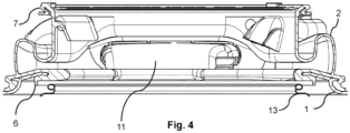
- Fig. 4 exhibits a schematic horizontal view of gasket 2 of Fig. 1 , as seen from below.
- Gasket 2 includes inner rim 6 fixed to tub 1, and outer rim 7 configured to be fixed to housing 3 as in Fig. 1 .
- Insert 11 appears to exhibit its direction towards drum 13, its direction appearing to be vertically downwards in Fig. 4 , for properly guiding the air flow to laundry placed and being tumbled in drum 13.
- the invention provides separate insert 11 for guiding the hot air flow through gasket 2, insert 11 keeping the air flow away from closely contacting gasket 11 itself and thereby protecting gasket 11 from possibly excessive thermal load. Eventually, the air flow is also kept away from immediately contacting door 5, thereby keeping low thermal load to door 5.
- Such thermal load may not be a problem for the material of door 5, which may be glass according to common practice, but it may be a problem if door 5 thus loaded is directly exposed to access by a user that might hurt itself by inadvertently touching the glass.
- the invention therefore allows to select a material for forming gasket 2 which has a limited resistance to high temperatures, thereby allowing selection of a material as convenient for a usual washing machine wherein any thermal load to gasket 2 is limited by the temperature of water boiling under normal pressure.
- a material may be EPDM rubber which is commercially available at low prices.
- the material of insert 11 may need to be selected to withstand higher thermal loads than the material of gasket 2 but insert 11 is a component of much less size and volume than gasket 2 and may therefore be made from a suitable and more expensive material such as silicone rubber.
Landscapes
- Engineering & Computer Science (AREA)
- Textile Engineering (AREA)
- Detail Structures Of Washing Machines And Dryers (AREA)
Abstract
Description
- The invention relates to a laundry care machine including a tub for receiving laundry to be dried by an air flow passing through said tub, a gasket connecting said tub to a housing and defining an access to said tub, and a door provided for closing the access sealed by said gasket, and said gasket including a connector for connecting a channel for providing the air flow to said tub.
- Document
CN 106 968 090 A discloses a laundry care machine as defined above. In that laundry care machine, the channel for providing the air flow opens directly into the gasket. Consequently, the air flow which has been heated just prior to reaching the gasket is guided by the structures of the gasket, subjecting these to a temperature which may exceed the temperature of boiling water at 100 °C on purpose of ascertaining proper and effective drying of humid laundry subject to care. - Accordingly, there is a need for further developing the laundry care machine as defined above for improving resistance to high temperatures as brought by an air flow heated on purpose of drying laundry thereby.
- Therefore, it is an object of the invention to provide a laundry care machine as defined above which includes a proper interface for providing guidance of a heated air flow through a gasket while avoiding excessive thermal load to the gasket.
- On purpose of solving this object the present invention provides a laundry care machine of the generic type as defined in the generic part of the independent claim attached which also includes the features of the characterizing part of said independent claim.
- Preferred embodiments of the invention are defined in dependent claims attached as well as in the subsequent disclosure. Such preferred embodiments may also be applied in mutual combinations insofar as possible under technical considerations to any extent, even if not specified herein explicitly.
- Accordingly the present invention provides, as a solution to the problem as defined above, a laundry care machine including a tub for receiving laundry to be dried by an air flow passing through said tub, a gasket connecting said tub to a housing and defining an access to said tub, and a door provided for closing said access sealed by said gasket, and said gasket including a connector for connecting a channel for providing the air flow to said tub, wherein an insert protruding into said connector is coupled to said connector and said channel, said insert including a lip projecting towards said tub and configured for directing the air flow into said tub.
- Advantages of the invention include that a separate insert is provided for guiding the hot air flow through the gasket, the insert keeping the air flow away from closely contacting the gasket itself and thereby protecting the gasket from possibly excessive thermal load. Eventually, the air flow is also kept away from immediately contacting the door, thereby avoiding excessive thermal load to the door. Such thermal load may not be a problem for the material of the door, which is glass according to common practice, but it may be a problem if directly exposed to access by a user that might hurt itself by inadvertently touching the glass.
- The invention therefore allows to select a material for forming the gasket which has a limited resistance to high temperatures, thereby allowing selection of a material as convenient for a usual washing machine wherein any thermal load to the gasket is limited by the temperature of boiling water. Such material may be EPDM rubber which is commercially available at low prices. The material of the insert needs to be selected to withstand higher thermal loads, but the insert is a component of much less size and volume than the gasket and may therefore be made from a suitable and more expensive material such as silicone rubber.
- Principally the invention may be applied to any laundry care machine which provides a hot air flow for any purpose. In particular, the household appliance may be a laundry care machine a washer-dryer dedicated to washing and drying batches of laundry.
- In accordance with a preferred embodiment of the invention, said lip defines a nozzle in said insert. Such nozzle is preferably applied for forming a jet of the air flow and directing such jet into the tub, thereby avoiding direct contact between the air flow and the gasket as much as possible. Given that the air flow will be rather hot in most cases, this will avoid undue thermal load to the gasket.
- In accordance with another preferred embodiment of the invention, said insert is fixed between said connector and said channel. Thereby the insert provides heat shielding between the channel and the gasket, which also contributes to avoiding direct contact between the air flow and the gasket as much as possible, and, in case that the air flow is rather hot, avoiding undue thermal load to the gasket.
- In accordance with a further preferred embodiment of the invention, said insert protrudes into said connector with a lateral distance from said connector. This effectively insulates the gasket's connector from the air flow and any thermal load that the air flow may cause, again contributing to avoiding direct contact between the air flow and the gasket as much as possible, and, in case that the air flow is rather hot, avoiding undue thermal load to the gasket. More preferred, distance ribs are provided between said connector and said insert for defining said lateral distance, thereby improving thermal insulation between the air flow and the gasket.
- In accordance with an additional preferred embodiment of the invention, said insert has a cross-section which is stretched along a first axis and includes a flat section between two rounded end sections. Such shape of the insert forms the air flow for efficient insertion into the tub while keeping it away from structures of the gasket and avoiding undue thermal load to the gasket. More preferred, the insert includes reinforcing ribs placed in the flat section which improve the insert's rigidity and assist in keeping the proper lateral distance between the insert and the connector.
- In accordance with yet another preferred embodiment of the invention, said connector surrounds said insert with an essentially constant lateral distance, thereby providing improved thermal insulation between the insert and the gasket's connector.
- In accordance with yet a further preferred embodiment of the invention, said gasket includes an inner rim configured to be fixed to said tub, and an outer rim configured to be fixed to said housing, and a sealing flange for conforming to said door upon closing said access. Thereby, proper sealing between the tub, the housing, and the door and allowing mutual movement between the tub and the housing is provided.
- In accordance with yet an additional preferred embodiment of the invention, said gasket and said insert consist of rubber materials. Thereby, the gasket and the insert may accommodate mutual movements between the tub and the housing while ascertaining their own proper sealing and insulating functions upon laundry being tumbled in the tub upon care treatment. More preferred, said gasket consists of a first rubber material having a first maximum operating temperature and said insert consists of a second rubber material having a second maximum operating temperature, wherein the second operating temperature is higher than the first maximum operating temperature. Thereby, the rubber material of the gasket may be selected for proper functioning under thermal and mechanical loads as regularly occurring when washing laundry, proper functioning also including proper sealing and inclusion of laundry treating liquid such as water and suds in the tub, and the rubber material of the insert may be selected independently for proper functioning under thermal and mechanical loads as regularly occurring when drying laundry, proper functioning including proper sealing of a hot air flow applied for drying. Even more preferred, the first maximum operating temperature is about 100 °C and thereby equates the boiling temperature of water under normal pressure, and the second maximum operating temperature is about 125 °C which is a maximum temperature preferred for an air flow applicable to drying laundry. Still more preferred, the first rubber material is an EPDM rubber material, and the second rubber material is a silicone rubber material. Silicone rubber material is relatively expensive as compared to EPDM rubber material, but EPDM rubber material has proper elasticity and durability for application in the gasket on purpose of proper sealing during any laundry washing process. Therefore, the gasket with its connector may be constituted of EPDM rubber material according to well-established practice. Application of relatively expensive silicone rubber material may be reserved to the insert for direct exposure to the relatively hot air flow applied for drying. Specifically, the EPDM rubber material selected for constituting the gasket may be 8 EP 38I material obtained from supplier Cikautxo Group, and the silicone rubber material selected for constituting the insert may be 3 SI material obtained from the same supplier. Thereby, the gasket and the insert may be formed integrally each by respective injection moulding.
- In accordance with still another preferred embodiment of the invention, a drum is rotatably disposed in said tub for receiving the laundry and configured for tumbling the laundry during any care process such as washing and drying.
- In accordance with still a further preferred embodiment of the invention, the laundry care machine is configured as a washer-dryer for washing and drying laundry.
- Various preferred embodiments of the invention are explained in detail subsequently with reference to the Figures of the attached drawing. These Figures show and exhibit as follows:
- Fig. 1
- a schematic view of a vertical section of a laundry care machine featuring a gasket and an insert;
- Fig. 2
- a partial view as indicated by the line with label "II" in
Fig. 1 ; - Fig. 3
- a partial view as indicated by the circle with labels "III" in
Fig. 1 ; and - Fig. 4
- a schematic horizontal view of the gasket of
Fig. 1 . - As shown in detail in
Fig. 1 , a laundry care machine includes atub 1 for receiving laundry to be dried by an air flow passing throughtub 1, agasket 2 connectingtub 1 to ahousing 3 and defining anaccess 4 to saidtub 1. Adoor 5 is provided forclosing access 4 sealed bygasket 2. - Tub 1 being swingably suspended in
housing 3 on purpose of absorbing reaction forces generated upon tumbling laundry intub 1,gasket 2 is provided on purpose of providing a seal between the inside oftub 1, the inside ofhousing 3 outsidetub 1, and the outside of the laundry care machine. For thesereasons gasket 2 is made from an elastic rubber, specifically an EPDM rubber, to provide sealing which is stable and reliable under swinging movements oftub 1 withinhousing 3, and stable also under subjection to chemicals such as usually present in suds prepared for washing, rinsing, or softening laundry. The rubber material ofgasket 2 is conventionally selected to withstand all temperatures that might occur during care of laundry, specifically washing of laundry, whereby a minimum operating temperature may be set at or near 0 °C, which is the freezing point of water at normal pressure, and a maximum operating temperature may be set at 100 °C, which is the boiling point of water at normal pressure.Gasket 2 includes aninner rim 6 fixed totub 1, and anouter rim 7 fixed tohousing 3, and a sealingflange 8 for conforming todoor 5 upon closing saidaccess 4. It may be noted thatFig. 1 does not show sealingflange 8 conform todoor 5 as it closesaccess 4 but sealingflange 8 as exposed whendoor 5 has been opened. - In the present embodiment the laundry care machine is provided for washing laundry as well as drying laundry, on purpose of which means are added to the laundry care machine for providing a circulating air flow to humid laundry in
tub 1. These means include a fan for driving the air flow, a heater for heating the air flow, and a condenser for extracting humidity from the air flow, all not shown in the drawing for the sake of clarity. In addition,gasket 2 includes aconnector 9 for connecting achannel 10, wherein the fan, the heater, and the condenser are included, for providing the air flow totub 1. - Further, an
insert 11 protruding intoconnector 9 is coupled toconnector 9 andchannel 10, insert 11 including alip 12 projecting towardstub 1 and configured for directing the air flow intotub 1.Lip 12 defines a nozzle ininsert 11.Insert 11 is fixed betweenchannel 10 and saidconnector 9 and protrudes intoconnector 9 with a lateral distance fromconnector 9. Thereby, the air flow passing fromchannel 10 totub 1 is isolated fromconnector 9. Considering that it may be desired to heat the air flow prior to enteringtub 1 for improving pickup of humidity from humid laundry place intub 1, a limitation of operating temperature ofgasket 2's material may, at least to some extent, be withdrawn from pertinence in view of the temperature that the air flow passing intotub 1 may have, by selecting a proper material with an appropriately higher maximum operating temperature forinsert 11. - Accordingly, both
gasket 2 and insert 11 consist of rubber materials, whereingasket 2 consists of a first rubber material having a first maximum operating temperature and insert 11 consists of a second rubber material having a second maximum operating temperature, wherein the second operating temperature is higher than the first maximum operating temperature. Specifically, the first maximum operating temperature which applies togasket 2 is about 100 °C, and the second maximum operating temperature which applies to insert 11 is about 125 °C. While the first rubber material which constitutesgasket 2 is an EPDM rubber material, the second rubber material which constitutesinsert 11 is a silicone rubber material. Silicone rubber material being relatively expensive as compared to EPDM rubber material and EPDM rubber material having proper elasticity and durability for application ingasket 2, it is possible to constitutegasket 2 of EPDM rubber material according to well-established practice and reserve application of relatively expensive silicone rubber material to insert 11. Presently, the EPDM rubber material selected forgasket 2 is 8 EP 38I material obtained from supplier Cikautxo Group, and the silicone rubber material is 3 SI material obtained from the same supplier. Thereby,gasket 2 and insert 11 may be formed integrally by respective injection moulding. -
Insert 11 protruding intoconnector 9 withlip 12 projecting towardstub 1 and forming a nozzle, insert 11 is properly configured for directing the air flow directly intotub 1 without passing too close alonggasket 2. Thereby, excessive thermal load upongasket 2 by the air flow having a temperature well above 100°C such as 125 °C is reliably avoided. Likewise, contact between the air flow and laundry being received and tumbled in adrum 13 rotatably disposed intub 1 is improved, thereby increasing effectivity of the drying process applying the air flow. -
Fig. 2 shows an enlarged portion of the view exhibited byFig. 1 , as indicated by the circle labelled II.Fig. 2 exhibits connector 9 withinsert 11 inserted and fixed into an annularfirst groove 14. Asecond groove 15 is formed inconnector 9 abovefirst groove 14 and insert 11 for receiving a corresponding part ofchannel 10, not shown inFig. 2 for the sake of clarity. Anannular shoulder 16 is provided ininsert 11 forseating channel 10, thereby avoiding any direct contact betweenchannel 10 andconnector 9 as apparent fromFig. 1 , and as appropriate for avoiding undue thermal load onconnector 9 during operation. -
Fig. 3 exhibits a transversal section throughconnector 9 and insert 11, as indicated by the line labelled "III" inFig. 1 . Accordingly,distance ribs 17 are provided betweenconnector 9 and insert 11 for defining an essentially constant lateral distance betweenconnector 9 and insert 11. As well asconnector 9, insert 11 has a cross-section which is shaped as a racetrack and stretched along afirst axis 18 and includes aflat section 19 between tworounded end sections 20.Insert 11 further includes reinforcingribs 21 placed in theflat section 19, providing structural stability to insert 11 andconnector 9. -
Fig. 4 exhibits a schematic horizontal view ofgasket 2 ofFig. 1 , as seen from below.Gasket 2 includesinner rim 6 fixed totub 1, andouter rim 7 configured to be fixed tohousing 3 as inFig. 1 .Insert 11 appears to exhibit its direction towardsdrum 13, its direction appearing to be vertically downwards inFig. 4 , for properly guiding the air flow to laundry placed and being tumbled indrum 13. - The invention provides
separate insert 11 for guiding the hot air flow throughgasket 2, insert 11 keeping the air flow away from closely contactinggasket 11 itself and thereby protectinggasket 11 from possibly excessive thermal load. Eventually, the air flow is also kept away from immediately contactingdoor 5, thereby keeping low thermal load todoor 5. Such thermal load may not be a problem for the material ofdoor 5, which may be glass according to common practice, but it may be a problem ifdoor 5 thus loaded is directly exposed to access by a user that might hurt itself by inadvertently touching the glass. - The invention therefore allows to select a material for forming
gasket 2 which has a limited resistance to high temperatures, thereby allowing selection of a material as convenient for a usual washing machine wherein any thermal load togasket 2 is limited by the temperature of water boiling under normal pressure. Such material may be EPDM rubber which is commercially available at low prices. The material ofinsert 11 may need to be selected to withstand higher thermal loads than the material ofgasket 2 but insert 11 is a component of much less size and volume thangasket 2 and may therefore be made from a suitable and more expensive material such as silicone rubber. -
- 1
- Tub
- 2
- Gasket
- 3
- Housing
- 4
- Access
- 5
- Door
- 6
- Inner rim
- 7
- Outer rim
- 8
- Sealing flange
- 9
- Connector
- 10
- Channel
- 11
- Insert
- 12
- Lip
- 13
- Drum
- 14
- First groove
- 15
- Second groove
- 16
- Shoulder
- 17
- Distance rib
- 18
- First axis
- 19
- Flat section
- 20
- Rounded section
- 21
- Reinforcing rib
Claims (15)
- A laundry care machine including a tub (1) for receiving laundry to be dried by an air flow passing through said tub (1), a gasket (2) connecting said tub (1) to a housing (3) and defining an access (4) to said tub (1), and a door (5) provided for closing the access (4) sealed by said gasket (2), and said gasket (2) including a connector (9) for connecting a channel (10) for providing the air flow to said tub (1), characterized in that an insert (11) protruding into the connector (9) is coupled to said connector (9) and said channel (10), said insert (11) including a lip (12) projecting towards said tub (1) and configured for directing the air flow into said tub (1).
- The laundry care machine according to claim 1, wherein said lip (12) defines a nozzle in said insert (11).
- The laundry care machine according to one of the preceding claims, wherein said insert (11) is fixed between said connector (9) and said channel (10).
- The laundry care machine according to one of the preceding claims, wherein said insert (11) protrudes into said connector (9) with a lateral distance from said connector (9).
- The laundry care machine according to claim 4, wherein distance ribs (17) are provided between said connector (9) and said insert (11) for defining said lateral distance.
- The laundry care machine according to one of the preceding claims, wherein said insert (11) has a cross-section which is stretched along a first axis (18) and includes a flat section (19) between two rounded end sections (20).
- The laundry care machine according to claim 6, wherein said insert (11) includes reinforcing ribs (21) placed in said flat section (19).
- The laundry care machine according to one of claims 4 to 7, wherein said connector (9) surrounds said insert (11) with an essentially constant lateral distance.
- The laundry care machine according to one of the preceding claims, wherein said gasket (2) includes an inner rim (6) configured to be fixed to said tub (1), and an outer rim (7) configured to be fixed to said housing (3), and a sealing flange (8) for conforming to said door (5) upon closing said access (4).
- The laundry care machine according to one of the preceding claims, wherein said gasket (2) and said insert (11) consist of rubber materials.
- The laundry care machine according to claim 10, wherein said gasket (2) consists of a first rubber material having a first maximum operating temperature and said insert (11) consists of a second rubber material having a second maximum operating temperature, wherein said second operating temperature is higher than said first maximum operating temperature.
- The laundry care machine according to claim 11, wherein said first maximum operating temperature is about 100 °C, and said second maximum operating temperature is about 125 °C.
- The laundry care machine according to one of claims 10 and 11, wherein said first rubber material is an EPDM rubber material, and said second rubber material is a silicone rubber material.
- The laundry care machine according to one of the preceding claims, wherein a drum (13) is rotatably disposed in said tub (1) for receiving the laundry and configured for tumbling the laundry during care.
- The laundry machine according to any preceding claim which is configured as a washer-dryer for washing and drying laundry.
Priority Applications (2)
| Application Number | Priority Date | Filing Date | Title |
|---|---|---|---|
| EP22156757.1A EP4227457B1 (en) | 2022-02-15 | 2022-02-15 | Laundry care machine including a gasket and a connector |
| CN202310102580.4A CN116607307A (en) | 2022-02-15 | 2023-02-13 | Laundry care machine comprising a washer and a connector |
Applications Claiming Priority (1)
| Application Number | Priority Date | Filing Date | Title |
|---|---|---|---|
| EP22156757.1A EP4227457B1 (en) | 2022-02-15 | 2022-02-15 | Laundry care machine including a gasket and a connector |
Publications (2)
| Publication Number | Publication Date |
|---|---|
| EP4227457A1 true EP4227457A1 (en) | 2023-08-16 |
| EP4227457B1 EP4227457B1 (en) | 2025-07-30 |
Family
ID=87699428
Family Applications (1)
| Application Number | Title | Priority Date | Filing Date |
|---|---|---|---|
| EP22156757.1A Active EP4227457B1 (en) | 2022-02-15 | 2022-02-15 | Laundry care machine including a gasket and a connector |
Country Status (2)
| Country | Link |
|---|---|
| EP (1) | EP4227457B1 (en) |
| CN (1) | CN116607307A (en) |
Citations (4)
| Publication number | Priority date | Publication date | Assignee | Title |
|---|---|---|---|---|
| WO2017005319A1 (en) * | 2015-07-08 | 2017-01-12 | Arcelik Anonim Sirketi | Door boot gasket for laundry washer-dryer |
| CN106968090A (en) | 2016-01-14 | 2017-07-21 | 博西华电器(江苏)有限公司 | Dryer |
| US20200248381A1 (en) * | 2019-02-01 | 2020-08-06 | Lg Electronics Inc. | Laundry treating apparatus |
| US20200270793A1 (en) * | 2016-11-17 | 2020-08-27 | Lg Electronics Inc. | Clothing treatment apparatus |
-
2022
- 2022-02-15 EP EP22156757.1A patent/EP4227457B1/en active Active
-
2023
- 2023-02-13 CN CN202310102580.4A patent/CN116607307A/en active Pending
Patent Citations (4)
| Publication number | Priority date | Publication date | Assignee | Title |
|---|---|---|---|---|
| WO2017005319A1 (en) * | 2015-07-08 | 2017-01-12 | Arcelik Anonim Sirketi | Door boot gasket for laundry washer-dryer |
| CN106968090A (en) | 2016-01-14 | 2017-07-21 | 博西华电器(江苏)有限公司 | Dryer |
| US20200270793A1 (en) * | 2016-11-17 | 2020-08-27 | Lg Electronics Inc. | Clothing treatment apparatus |
| US20200248381A1 (en) * | 2019-02-01 | 2020-08-06 | Lg Electronics Inc. | Laundry treating apparatus |
Also Published As
| Publication number | Publication date |
|---|---|
| EP4227457B1 (en) | 2025-07-30 |
| CN116607307A (en) | 2023-08-18 |
Similar Documents
| Publication | Publication Date | Title |
|---|---|---|
| KR100672490B1 (en) | Steam generator for clothes processing device and clothes processing device using same | |
| EP1917392B1 (en) | Operating method for laundry machine | |
| US7356945B2 (en) | Operation method and device for combination dryer | |
| RU2546425C2 (en) | Sealing sleeve for washing machine | |
| KR102127385B1 (en) | Operating method for laundry machine | |
| EP1319100B1 (en) | Laundry appliance | |
| JPH059479U (en) | Fully automatic washing machine | |
| EP1861538B1 (en) | Method for controlling a washing machine | |
| AU2017204092B2 (en) | Laundry machine | |
| AU2006280592B2 (en) | Drying duct assembly and washing machine having the same | |
| EP4227457B1 (en) | Laundry care machine including a gasket and a connector | |
| KR20060007469A (en) | washer | |
| AU2013245562B2 (en) | Laundry treatment machine | |
| CN113174734B (en) | Control method, device, equipment and computer readable storage medium | |
| US20180363197A1 (en) | Wall-mounted washing machine | |
| KR20090028037A (en) | Drum washing machine | |
| JP2008253589A (en) | Drum type washer / dryer | |
| KR20080072188A (en) | Laundry treatment equipment | |
| CN216107708U (en) | Drum washing and drying machine and door seal thereof | |
| US20040148979A1 (en) | Washing machine | |
| CN110318227A (en) | Sleeve and washings handle utensil | |
| KR101176486B1 (en) | Vapor upsteam interceptor of washing machine | |
| KR101033586B1 (en) | Drum washing machine | |
| CN219568346U (en) | Pulsator washing machine with dewatering belt drying function | |
| US12344980B2 (en) | Method for operating an automatic washing machine, and automatic washing machine |
Legal Events
| Date | Code | Title | Description |
|---|---|---|---|
| PUAI | Public reference made under article 153(3) epc to a published international application that has entered the european phase |
Free format text: ORIGINAL CODE: 0009012 |
|
| STAA | Information on the status of an ep patent application or granted ep patent |
Free format text: STATUS: THE APPLICATION HAS BEEN PUBLISHED |
|
| AK | Designated contracting states |
Kind code of ref document: A1 Designated state(s): AL AT BE BG CH CY CZ DE DK EE ES FI FR GB GR HR HU IE IS IT LI LT LU LV MC MK MT NL NO PL PT RO RS SE SI SK SM TR |
|
| STAA | Information on the status of an ep patent application or granted ep patent |
Free format text: STATUS: REQUEST FOR EXAMINATION WAS MADE |
|
| 17P | Request for examination filed |
Effective date: 20240216 |
|
| RBV | Designated contracting states (corrected) |
Designated state(s): AL AT BE BG CH CY CZ DE DK EE ES FI FR GB GR HR HU IE IS IT LI LT LU LV MC MK MT NL NO PL PT RO RS SE SI SK SM TR |
|
| GRAP | Despatch of communication of intention to grant a patent |
Free format text: ORIGINAL CODE: EPIDOSNIGR1 |
|
| STAA | Information on the status of an ep patent application or granted ep patent |
Free format text: STATUS: GRANT OF PATENT IS INTENDED |
|
| RIC1 | Information provided on ipc code assigned before grant |
Ipc: D06F 58/02 20060101ALN20250218BHEP Ipc: D06F 25/00 20060101ALN20250218BHEP Ipc: D06F 58/04 20060101ALI20250218BHEP Ipc: D06F 58/20 20060101ALI20250218BHEP Ipc: D06F 37/26 20060101AFI20250218BHEP |
|
| INTG | Intention to grant announced |
Effective date: 20250303 |
|
| GRAS | Grant fee paid |
Free format text: ORIGINAL CODE: EPIDOSNIGR3 |
|
| GRAA | (expected) grant |
Free format text: ORIGINAL CODE: 0009210 |
|
| STAA | Information on the status of an ep patent application or granted ep patent |
Free format text: STATUS: THE PATENT HAS BEEN GRANTED |
|
| AK | Designated contracting states |
Kind code of ref document: B1 Designated state(s): AL AT BE BG CH CY CZ DE DK EE ES FI FR GB GR HR HU IE IS IT LI LT LU LV MC MK MT NL NO PL PT RO RS SE SI SK SM TR |
|
| REG | Reference to a national code |
Ref country code: GB Ref legal event code: FG4D |
|
| REG | Reference to a national code |
Ref country code: CH Ref legal event code: EP |
|
| REG | Reference to a national code |
Ref country code: DE Ref legal event code: R096 Ref document number: 602022018264 Country of ref document: DE |
|
| REG | Reference to a national code |
Ref country code: IE Ref legal event code: FG4D |
|
| REG | Reference to a national code |
Ref country code: NL Ref legal event code: MP Effective date: 20250730 |
|
| REG | Reference to a national code |
Ref country code: AT Ref legal event code: MK05 Ref document number: 1819024 Country of ref document: AT Kind code of ref document: T Effective date: 20250730 |
|
| PG25 | Lapsed in a contracting state [announced via postgrant information from national office to epo] |
Ref country code: PT Free format text: LAPSE BECAUSE OF FAILURE TO SUBMIT A TRANSLATION OF THE DESCRIPTION OR TO PAY THE FEE WITHIN THE PRESCRIBED TIME-LIMIT Effective date: 20251202 |
|
| PG25 | Lapsed in a contracting state [announced via postgrant information from national office to epo] |
Ref country code: IS Free format text: LAPSE BECAUSE OF FAILURE TO SUBMIT A TRANSLATION OF THE DESCRIPTION OR TO PAY THE FEE WITHIN THE PRESCRIBED TIME-LIMIT Effective date: 20251130 |
|
| PG25 | Lapsed in a contracting state [announced via postgrant information from national office to epo] |
Ref country code: NO Free format text: LAPSE BECAUSE OF FAILURE TO SUBMIT A TRANSLATION OF THE DESCRIPTION OR TO PAY THE FEE WITHIN THE PRESCRIBED TIME-LIMIT Effective date: 20251030 |
|
| REG | Reference to a national code |
Ref country code: LT Ref legal event code: MG9D |
|
| PG25 | Lapsed in a contracting state [announced via postgrant information from national office to epo] |
Ref country code: AT Free format text: LAPSE BECAUSE OF FAILURE TO SUBMIT A TRANSLATION OF THE DESCRIPTION OR TO PAY THE FEE WITHIN THE PRESCRIBED TIME-LIMIT Effective date: 20250730 |
|
| PG25 | Lapsed in a contracting state [announced via postgrant information from national office to epo] |
Ref country code: FI Free format text: LAPSE BECAUSE OF FAILURE TO SUBMIT A TRANSLATION OF THE DESCRIPTION OR TO PAY THE FEE WITHIN THE PRESCRIBED TIME-LIMIT Effective date: 20250730 |
|
| PG25 | Lapsed in a contracting state [announced via postgrant information from national office to epo] |
Ref country code: NL Free format text: LAPSE BECAUSE OF FAILURE TO SUBMIT A TRANSLATION OF THE DESCRIPTION OR TO PAY THE FEE WITHIN THE PRESCRIBED TIME-LIMIT Effective date: 20250730 Ref country code: HR Free format text: LAPSE BECAUSE OF FAILURE TO SUBMIT A TRANSLATION OF THE DESCRIPTION OR TO PAY THE FEE WITHIN THE PRESCRIBED TIME-LIMIT Effective date: 20250730 |
|
| PG25 | Lapsed in a contracting state [announced via postgrant information from national office to epo] |
Ref country code: GR Free format text: LAPSE BECAUSE OF FAILURE TO SUBMIT A TRANSLATION OF THE DESCRIPTION OR TO PAY THE FEE WITHIN THE PRESCRIBED TIME-LIMIT Effective date: 20251031 |
|
| PG25 | Lapsed in a contracting state [announced via postgrant information from national office to epo] |
Ref country code: SE Free format text: LAPSE BECAUSE OF FAILURE TO SUBMIT A TRANSLATION OF THE DESCRIPTION OR TO PAY THE FEE WITHIN THE PRESCRIBED TIME-LIMIT Effective date: 20250730 |
|
| PG25 | Lapsed in a contracting state [announced via postgrant information from national office to epo] |
Ref country code: LV Free format text: LAPSE BECAUSE OF FAILURE TO SUBMIT A TRANSLATION OF THE DESCRIPTION OR TO PAY THE FEE WITHIN THE PRESCRIBED TIME-LIMIT Effective date: 20250730 |
|
| PG25 | Lapsed in a contracting state [announced via postgrant information from national office to epo] |
Ref country code: BG Free format text: LAPSE BECAUSE OF FAILURE TO SUBMIT A TRANSLATION OF THE DESCRIPTION OR TO PAY THE FEE WITHIN THE PRESCRIBED TIME-LIMIT Effective date: 20250730 Ref country code: PL Free format text: LAPSE BECAUSE OF FAILURE TO SUBMIT A TRANSLATION OF THE DESCRIPTION OR TO PAY THE FEE WITHIN THE PRESCRIBED TIME-LIMIT Effective date: 20250730 |
|
| PG25 | Lapsed in a contracting state [announced via postgrant information from national office to epo] |
Ref country code: RS Free format text: LAPSE BECAUSE OF FAILURE TO SUBMIT A TRANSLATION OF THE DESCRIPTION OR TO PAY THE FEE WITHIN THE PRESCRIBED TIME-LIMIT Effective date: 20251030 |
|
| PG25 | Lapsed in a contracting state [announced via postgrant information from national office to epo] |
Ref country code: ES Free format text: LAPSE BECAUSE OF FAILURE TO SUBMIT A TRANSLATION OF THE DESCRIPTION OR TO PAY THE FEE WITHIN THE PRESCRIBED TIME-LIMIT Effective date: 20250730 |
|
| PG25 | Lapsed in a contracting state [announced via postgrant information from national office to epo] |
Ref country code: SM Free format text: LAPSE BECAUSE OF FAILURE TO SUBMIT A TRANSLATION OF THE DESCRIPTION OR TO PAY THE FEE WITHIN THE PRESCRIBED TIME-LIMIT Effective date: 20250730 |
|
| PG25 | Lapsed in a contracting state [announced via postgrant information from national office to epo] |
Ref country code: DK Free format text: LAPSE BECAUSE OF FAILURE TO SUBMIT A TRANSLATION OF THE DESCRIPTION OR TO PAY THE FEE WITHIN THE PRESCRIBED TIME-LIMIT Effective date: 20250730 |
|
| PGFP | Annual fee paid to national office [announced via postgrant information from national office to epo] |
Ref country code: DE Payment date: 20260228 Year of fee payment: 5 |
|
| PG25 | Lapsed in a contracting state [announced via postgrant information from national office to epo] |
Ref country code: IT Free format text: LAPSE BECAUSE OF FAILURE TO SUBMIT A TRANSLATION OF THE DESCRIPTION OR TO PAY THE FEE WITHIN THE PRESCRIBED TIME-LIMIT Effective date: 20250730 |
|
| PGFP | Annual fee paid to national office [announced via postgrant information from national office to epo] |
Ref country code: TR Payment date: 20260212 Year of fee payment: 5 |
|
| PG25 | Lapsed in a contracting state [announced via postgrant information from national office to epo] |
Ref country code: CZ Free format text: LAPSE BECAUSE OF FAILURE TO SUBMIT A TRANSLATION OF THE DESCRIPTION OR TO PAY THE FEE WITHIN THE PRESCRIBED TIME-LIMIT Effective date: 20250730 |
|
| PG25 | Lapsed in a contracting state [announced via postgrant information from national office to epo] |
Ref country code: EE Free format text: LAPSE BECAUSE OF FAILURE TO SUBMIT A TRANSLATION OF THE DESCRIPTION OR TO PAY THE FEE WITHIN THE PRESCRIBED TIME-LIMIT Effective date: 20250730 Ref country code: SK Free format text: LAPSE BECAUSE OF FAILURE TO SUBMIT A TRANSLATION OF THE DESCRIPTION OR TO PAY THE FEE WITHIN THE PRESCRIBED TIME-LIMIT Effective date: 20250730 |