EP4227441A1 - Porous electrode with a catalytic activity towards co2 or co electrochemical and photo-electrochemical reduction - Google Patents
Porous electrode with a catalytic activity towards co2 or co electrochemical and photo-electrochemical reduction Download PDFInfo
- Publication number
- EP4227441A1 EP4227441A1 EP22156106.1A EP22156106A EP4227441A1 EP 4227441 A1 EP4227441 A1 EP 4227441A1 EP 22156106 A EP22156106 A EP 22156106A EP 4227441 A1 EP4227441 A1 EP 4227441A1
- Authority
- EP
- European Patent Office
- Prior art keywords
- molecular catalyst
- metal
- conductive
- metal oxide
- porous electrode
- Prior art date
- Legal status (The legal status is an assumption and is not a legal conclusion. Google has not performed a legal analysis and makes no representation as to the accuracy of the status listed.)
- Pending
Links
Images





Classifications
-
- C—CHEMISTRY; METALLURGY
- C25—ELECTROLYTIC OR ELECTROPHORETIC PROCESSES; APPARATUS THEREFOR
- C25B—ELECTROLYTIC OR ELECTROPHORETIC PROCESSES FOR THE PRODUCTION OF COMPOUNDS OR NON-METALS; APPARATUS THEREFOR
- C25B1/00—Electrolytic production of inorganic compounds or non-metals
- C25B1/01—Products
- C25B1/23—Carbon monoxide or syngas
-
- C—CHEMISTRY; METALLURGY
- C25—ELECTROLYTIC OR ELECTROPHORETIC PROCESSES; APPARATUS THEREFOR
- C25B—ELECTROLYTIC OR ELECTROPHORETIC PROCESSES FOR THE PRODUCTION OF COMPOUNDS OR NON-METALS; APPARATUS THEREFOR
- C25B1/00—Electrolytic production of inorganic compounds or non-metals
- C25B1/50—Processes
- C25B1/55—Photoelectrolysis
-
- C—CHEMISTRY; METALLURGY
- C25—ELECTROLYTIC OR ELECTROPHORETIC PROCESSES; APPARATUS THEREFOR
- C25B—ELECTROLYTIC OR ELECTROPHORETIC PROCESSES FOR THE PRODUCTION OF COMPOUNDS OR NON-METALS; APPARATUS THEREFOR
- C25B11/00—Electrodes; Manufacture thereof not otherwise provided for
- C25B11/02—Electrodes; Manufacture thereof not otherwise provided for characterised by shape or form
- C25B11/03—Electrodes; Manufacture thereof not otherwise provided for characterised by shape or form perforated or foraminous
- C25B11/031—Porous electrodes
-
- C—CHEMISTRY; METALLURGY
- C25—ELECTROLYTIC OR ELECTROPHORETIC PROCESSES; APPARATUS THEREFOR
- C25B—ELECTROLYTIC OR ELECTROPHORETIC PROCESSES FOR THE PRODUCTION OF COMPOUNDS OR NON-METALS; APPARATUS THEREFOR
- C25B11/00—Electrodes; Manufacture thereof not otherwise provided for
- C25B11/04—Electrodes; Manufacture thereof not otherwise provided for characterised by the material
- C25B11/051—Electrodes formed of electrocatalysts on a substrate or carrier
- C25B11/054—Electrodes comprising electrocatalysts supported on a carrier
-
- C—CHEMISTRY; METALLURGY
- C25—ELECTROLYTIC OR ELECTROPHORETIC PROCESSES; APPARATUS THEREFOR
- C25B—ELECTROLYTIC OR ELECTROPHORETIC PROCESSES FOR THE PRODUCTION OF COMPOUNDS OR NON-METALS; APPARATUS THEREFOR
- C25B11/00—Electrodes; Manufacture thereof not otherwise provided for
- C25B11/04—Electrodes; Manufacture thereof not otherwise provided for characterised by the material
- C25B11/051—Electrodes formed of electrocatalysts on a substrate or carrier
- C25B11/055—Electrodes formed of electrocatalysts on a substrate or carrier characterised by the substrate or carrier material
- C25B11/069—Electrodes formed of electrocatalysts on a substrate or carrier characterised by the substrate or carrier material consisting of at least one single element and at least one compound; consisting of two or more compounds
-
- C—CHEMISTRY; METALLURGY
- C25—ELECTROLYTIC OR ELECTROPHORETIC PROCESSES; APPARATUS THEREFOR
- C25B—ELECTROLYTIC OR ELECTROPHORETIC PROCESSES FOR THE PRODUCTION OF COMPOUNDS OR NON-METALS; APPARATUS THEREFOR
- C25B11/00—Electrodes; Manufacture thereof not otherwise provided for
- C25B11/04—Electrodes; Manufacture thereof not otherwise provided for characterised by the material
- C25B11/051—Electrodes formed of electrocatalysts on a substrate or carrier
- C25B11/073—Electrodes formed of electrocatalysts on a substrate or carrier characterised by the electrocatalyst material
- C25B11/091—Electrodes formed of electrocatalysts on a substrate or carrier characterised by the electrocatalyst material consisting of at least one catalytic element and at least one catalytic compound; consisting of two or more catalytic elements or catalytic compounds
- C25B11/095—Electrodes formed of electrocatalysts on a substrate or carrier characterised by the electrocatalyst material consisting of at least one catalytic element and at least one catalytic compound; consisting of two or more catalytic elements or catalytic compounds at least one of the compounds being organic
-
- C—CHEMISTRY; METALLURGY
- C25—ELECTROLYTIC OR ELECTROPHORETIC PROCESSES; APPARATUS THEREFOR
- C25B—ELECTROLYTIC OR ELECTROPHORETIC PROCESSES FOR THE PRODUCTION OF COMPOUNDS OR NON-METALS; APPARATUS THEREFOR
- C25B3/00—Electrolytic production of organic compounds
- C25B3/20—Processes
- C25B3/21—Photoelectrolysis
-
- C—CHEMISTRY; METALLURGY
- C25—ELECTROLYTIC OR ELECTROPHORETIC PROCESSES; APPARATUS THEREFOR
- C25B—ELECTROLYTIC OR ELECTROPHORETIC PROCESSES FOR THE PRODUCTION OF COMPOUNDS OR NON-METALS; APPARATUS THEREFOR
- C25B3/00—Electrolytic production of organic compounds
- C25B3/20—Processes
- C25B3/25—Reduction
- C25B3/26—Reduction of carbon dioxide
-
- Y—GENERAL TAGGING OF NEW TECHNOLOGICAL DEVELOPMENTS; GENERAL TAGGING OF CROSS-SECTIONAL TECHNOLOGIES SPANNING OVER SEVERAL SECTIONS OF THE IPC; TECHNICAL SUBJECTS COVERED BY FORMER USPC CROSS-REFERENCE ART COLLECTIONS [XRACs] AND DIGESTS
- Y02—TECHNOLOGIES OR APPLICATIONS FOR MITIGATION OR ADAPTATION AGAINST CLIMATE CHANGE
- Y02P—CLIMATE CHANGE MITIGATION TECHNOLOGIES IN THE PRODUCTION OR PROCESSING OF GOODS
- Y02P20/00—Technologies relating to chemical industry
- Y02P20/10—Process efficiency
- Y02P20/133—Renewable energy sources, e.g. sunlight
Definitions
- the invention relates to a porous electrode with a catalytic activity towards CO 2 or CO electrochemical and photo-electrochemical reduction.
- a first solution remains the use of renewable energies, which is becoming more and more common to produce electricity and avoid concomitant production of CO 2 .
- a second solution is to perceive CO 2 as a source of elements like carbon or oxygen, and not as a waste.
- Molecular catalysts that combine high selectivity and high current density for CO 2 electrochemical reduction to CO or other chemical feedstock are in high demand.
- Molecular transition metal catalysts offer the distinct advantage of allowing for the fine-tuning of the primary and secondary coordination spheres by manipulating the chelating environment and the steric and electronic effects of the ligands.
- the ability to improve catalytic efficiency and product selectivity through the rational optimization of the ligand structure is a feature not accessible to the solid-state catalysts common to current pilot-scale electrolyzer units.
- An ALD mummy-based assembly has been used to demonstrate photoelectrochemical dehydrogenation of hydroquinone.
- the encapsulation is carried out by ALD, i.e. using a gas, which makes the encapsulation more complex.
- ALD atomic layer deposition
- the nature of the metal oxide and the molecular catalyst cannot be changed easily.
- the invention thus proposes to contribute to CO 2 emission mitigation by recycling it.
- the invention proposes active electrodes and photoelectrodes with a catalytic activity towards CO 2 reduction and a new way to prepare very active electrodes and photoelectrodes with a catalytic activity towards CO 2 reduction.
- the most important aspect of the invention is the ability to insert and encapsulate with control homogeneous catalysts within structured oxide nanolayers, leading to higher catalytic activity, while using few molecular material and following very simple preparation method. Such an approach may further give additional stability to the catalytic sites and is versatile, the nature of the oxide may indeed be easily tuned as well as the nature of the encapsulated molecular catalyst.
- the invention relates to a porous electrode for electrochemical or photoelectrochemical reduction CO 2 or CO comprising:
- the catalytic activity is improved compared to the state of the art which does not encapsulate the molecular catalyst in the metal oxide MO layer, and the porous electrode is suitable for electrochemical or photoelectrochemical reduction.
- the molecular catalyst is without anchoring group. Thus, there is no need to functionalise the molecular catalyst.
- the conductive nanoporous catalytic matrix is formed by a continuous porous layer of metal oxide MO and the molecular catalyst in the structure of the continuous porous layer.
- the active/contact surface of the porous electrode is increased with this porous layer
- the conductive nanoporous catalytic matrix comprises an array of metal oxide coated nanowires on the surface of the substrate, each metal oxide coated nanowire being a metal oxide nanowire covered by a coating layer of metal oxide with nanopores and molecular catalyst which is in the coating layer.
- the surface area of the substrate is increased, which promotes catalytic activity.
- the deposition of the porous conductive catalytic matrix is a coating, which means that the shape imparted to the nanowires is retained.
- the porous electrode has a concentration of molecular catalyst equal or superior to 0.5 nmol per cm 2 of the porous electrode.
- concentration of molecular catalyst equal or superior to 0.5 nmol per cm 2 of the porous electrode.
- the porous electrode is presenting optical transmission higher than 60% at wavelengths between 350 and 1300 nm.
- the porous electrode is transparent, allowing its use at the surface (on top) of a photoelectrode or allowing to be easily combined to a photoelectrode.
- the substrate is a photoelectrode comprising:
- the whole system can be used as a photoelectrode allowing the energy produced by the photoelectrode to be used to carry out the reduction of CO 2 or CO.
- the molecular catalyst is water-soluble.
- the metal oxide can be deposited in an aqueous medium without losing the molecular catalyst encapsulated in the conductive nanoporous catalytic matrix.
- the molecular catalyst is chosen among: metal quaterpyridines, metal porphyrins, metal phthalocyanines or metal corroles, which presents water soluble substituents, with for example metal being Co, Ni, Sn, Cu or Fe.
- metal being Co, Ni, Sn, Cu or Fe.
- the metal oxide MO is chosen from the following list: aluminum oxide, titanium oxide, or a doped wide band gap metal oxide. More advantageously, the metal oxide MO is zinc oxide. These metal oxides are transparent and can therefore be integrated into photoreduction systems.
- the invention relates to a process for realizing a porous electrode for CO 2 or CO electrochemical or photoelectrochemical reduction on a conductive or conductive transparent or photoconductive substrate, the process comprising the following steps:
- the process allows to obtain porous electrodes which can be an active electrode or photoelectrode with a catalytic activity towards CO 2 or CO reduction.
- the process allows for porous electrodes with improved catalytic activity, while using few molecular material and following simple preparation method.
- Such an approach may further give additional stability to the catalytic sites and is versatile, since the nature of the oxide may be easily tuned as well as the nature of the encapsulated molecular catalyst.
- the solvent solution is a mixture comprising zinc salt such as zinc chloride and the molecular catalyst, the molecular catalyst being water soluble in the solvent solution which is water, and the electrodeposition being realized at a temperature inferior to 100°C.
- the solvent solution for the deposits is water, so it is easy to obtain, it is not expensive and it is a socalled green solvent solution, because the solvent solution is ecological.
- the molecular catalyst is chosen among: metal quaterpyridines, metal porphyrins, metal phthalocyanines or metal corroles, which present water soluble substituents, with for example metal being Co, Ni, Sn, Cu or Fe.
- metal being Co, Ni, Sn, Cu or Fe.
- the step b) of electrodeposition of the metal ions forms a conductive nanoporous catalytic matrix of metal oxide MO with nanopores, which encapsulates the molecular catalyst, directly on the substrate, to obtain a continuous porous layer.
- the process comprises a step a0) and a step b0) before the step a):
- the substrate has nanowires on its surface, which increase the effective surface of the electrode. This increases the catalytic activity of the resulting porous electrode.
- a porous electrode 1 for electrochemical or photoelectrochemical reduction CO 2 or CO as shown in figure 1 , comprising:
- metal oxide MO 4 there is a growth of the metal oxide MO 4 during the electrodeposition forming a structure of metal oxide MO 4 with nanopores and integrating the molecular catalyst 5.
- the molecular catalyst is in the structure of the metal oxide MO 4 and in the nanopores.
- the conductive nanoporous catalytic matrix 3 is on the substrate 2, 2a or 2b, which is a hybrid of a metal oxide MO 4 and a molecular catalyst 5, realized by electrodeposition, comprising metal oxide MO 4 with nanopores, which encapsulates the metal molecular catalyst 5, the nanopores of the metal oxide MO 4 being formed during the electrodeposition.
- the conductive nanoporous catalytic matrix 3 being a hybrid of a metal oxide MO 4 and a molecular catalyst 5 because the metal oxide MO 4 encapsulates the metal molecular catalyst 5, allows catalytic activity on the entire surface of the substrate.
- the molecular catalyst 5 remains in the conductive nanoporous catalytic matrix 3 without having been functionalized previously.
- the term "homogeneously" defines that the molecular catalyst 5 is uniformly distributed throughout the porous electrode 1 without forming aggregates.
- hybrid means that the conductive nanoporous catalytic matrix 3 is composed of disparate elements, a mixture.
- the porous electrode 1 can be transparent.
- the porous electrode 1 is transparent in the visible and near infrared range.
- the porous electrode 1 is presenting optical transmission higher than 60% at wavelengths between 250 and 1500 nm, more advantageously between 300 and 1450 nm, 350 and 1400 nm, 400 and 1350 nm or 450 and 1300 nm.
- the porous electrode 1 can be used on solar cells.
- the optical transmission is higher than 65%, 70%, 75%, 80%, 85%, 90% or 95%, for all the previous wavelength ranges.
- all components of the porous electrode 1 have an optical transmission higher than 60% at wavelengths at least between 350 and 1300 nm.
- the transparency of the components allows the visible light to pass through the nano porous or nanowire electrode for photoelectrochemical reduction.
- the substrate 2, 2a, 2b The substrate 2, 2a, 2b
- the substrate 2 is photoconductive 2b or conductive or transparent and conductive 2a.
- the substrate 2 may have a particular shape and/or surface structure.
- the surface structure may be porous, micro-structured, or nano-structured.
- the substrate 2 may have nanowires on its surface, or another nanostructure that increases the active surface (the contact area).
- the substrate 2 is an electrode 2a or a photoelectrode 2b.
- the substrate 2 can be a photoelectrode 2b comprising:
- the photoelectrode 2b is a simple or multijunction solar cell.
- the substrate 2 comprises at least a metal oxide conductive top layer.
- the metal oxide conductive top layer can be an aluminium doped zinc oxide, tin doped indium oxide (ITO), fluorine doped tin oxide (SnO 2 :F).
- the thickness of the top layer is superior to 10 nm.
- the conductive nanoporous catalytic matrix 3 is a hybrid of a metal oxide MO 4 and a molecular catalyst 5, realized by electrodeposition, comprising a metal oxide MO 4 which encapsulates the metal molecular catalyst 5 in the structure.
- the conductive nanoporous catalytic matrix 3 is on the substrate 2.
- the terms “the conductive nanoporous catalytic matrix” 3 can also be called indifferently: “nanostructured hybrid oxide layer for CO 2 or CO reduction”, “nanostructured catalytic material”, or “porous catalytic nanostructures”.
- the density and size of the nanopores depends on shape, size or type of molecular catalyst 5, the nanopores of metal oxide MO 4 are formed during the electrodeposition.
- the density and/or size of the nanopores can be modified by changing the molecular catalyst.
- the conductive nanoporous catalytic matrix 3 is transparent.
- the conductive nanoporous catalytic matrix 3 is formed by mixing of the metal oxide MO 4 and the molecular catalyst 5.
- the conductive nanoporous catalytic matrix 3 is formed by a continuous porous layer of metal oxide MO 4 and the molecular catalyst 5.
- the conductive nanoporous catalytic matrix 3 is formed by a continuous porous layer of metal oxide MO 4 and the molecular catalyst 5 in the structure of the continuous porous layer.
- the continuous porous layer has a thickness inferior to 1 micrometre.
- this thickness allows a good catalytic rate to be maintained by the transport phenomena in the conductive nanoporous catalytic matrix 3 (charge transport and CO 2 or CO and/or proton transport).
- continuous porous means that the layer comprising the metal oxide MO 4 structure covers the substrate 2, 2a, 2b with a uniform surface, and low roughness.
- the conductive nanoporous catalytic matrix 3 comprises an array of metal oxide coated nanowires 6 on the surface of the substrate 2, 2a, 2b, each metal oxide coated nanowire 6 being a metal oxide nanowire covered by a coating layer of metal oxide MO 4 with nanopores and molecular catalyst 5 which is in the coating layer, as shown in Figures 2 , 4a , 4b , 6 , 7 and 8 .
- coating layer means that said layer is a coating, the shape of the substrate 2 is preserved during the deposition of this coating, so the coating layer increases the thickness of the porous electrode 1 on the whole surface.
- these layers can be deposited on top of a conductive electrode 2, 2a or on the window layer of solar cells 2b such as a copper indium gallium selenide solar cell (CIGS).
- a conductive electrode 2, 2a or on the window layer of solar cells 2b such as a copper indium gallium selenide solar cell (CIGS).
- CIGS copper indium gallium selenide solar cell
- the coating layer having a thickness inferior to 50 nanometres.
- This thickness allows the structure of the substrate 2 and the shape of the nanowires 6 to be maintained.
- the nanowires 6 present a ratio length /diameter superior or equal to 1. More advantageously, the ratio thickness/diameter is superior to 2, 3, 4, 5, 6, 7, 8, 9 or 10.
- the thickness of the nanowires is the distance between the substrate (the base) and the tip of the nanowires.
- the conductive nanoporous catalytic matrix 3 is covered by a layer of another metal oxide 4.
- the additional layer protects the porous electrode 1 from corrosion of the electrolyte.
- the additional layer is SnO 2 , TiO 2 , or Al 2 O 3 .
- the molecular catalyst 5 The molecular catalyst 5
- the molecular catalyst 5 is integrated and encapsulated in said porous structure.
- the molecular catalyst 5 is embedded in the metal oxide structure and may also be in the nanopores of said porous layer.
- the metal catalyst 5 may be both in the bulk (volume of the layer) of the metal oxide and in the nanopores, due to co-deposition.
- the molecular catalyst 5 is soluble in the solution used for electrodeposition. More advantageously, the molecular catalyst 5 is water-soluble.
- the encapsulated water-soluble molecular catalyst in the conductive nanoporous catalytic matrix 3 is maintained in the conductive nanoporous catalytic matrix 3 even when in contact with an aqueous solution.
- the porosity of the conductive nanoporous catalytic electrode allows the molecular catalyst to be in contact with the electrolyte solution and with the CO 2 and CO gases to be reduced.
- the porosity also allows the release of the CO 2 and CO once reduced.
- the molecular catalyst 5 has a core with an earth-abundant transition metal such as Fe, Mn, Co, Ni, Sn, Cu or rare metals such as Ruthenium, Rhenium, Gold, Silver.
- an earth-abundant transition metal such as Fe, Mn, Co, Ni, Sn, Cu or rare metals such as Ruthenium, Rhenium, Gold, Silver.
- the molecular catalyst 5 is chosen among: metal quaterpyridines, metal porphyrins, metal corroles or metal phthalocyanines, which present water soluble substituents with for example metal being Co, Ni, Sn, Cu or Fe.
- the molecular catalyst 5 is chosen to reduce:
- the molecular catalyst 5 is chosen to reduce:
- the molecular catalyst 5 is without functions to fix it to the metal oxide MO 4 in the conductive nanoporous catalytic matrix 3.
- the molecular catalyst 5 is without anchoring group.
- the molecular catalyst 5 is not deposited using carboxylates, phosphonates, organosilanes, hydroxamates, and acetylacetonates functions that are usually appended to the ligand of the molecular catalyst s for immobilization on metal oxide 4 surfaces.
- the reduction of CO 2 or CO produces a selective product
- the selective product depends on the molecular catalyst 5.
- the porous electrode 1 has a concentration of molecular catalyst 5 equal or superior to 0.5 nmol per cm 2 of the porous electrode 1. More advantageously, the concentration of molecular catalyst in the structure is superior to 1 nmol /cm 2 , 2 nmol /cm 2 , 3 nmol /cm 2 , 4 nmol /cm 2 , 5 nmol /cm 2 , 6 nmol /cm 2 , or 7 nmol /cm 2 of the porous electrode 1.
- the porous electrode 1 has catalytic activity despite the low amount of molecular catalyst 5, furthermore the catalytic activity can be improved by increasing the amount of molecular catalyst 5.
- the metal oxide MO 4 The metal oxide MO 4
- the metal oxide MO 4 is chosen from the following list: aluminium oxide, titanium oxide, or a doped wide band gap metal oxide film. More advantageously, the metal oxide MO 4 is zinc oxide (ZnO).
- the doped wide band gap metal oxide film has E g > 2.4 eV.
- ZnO presents remarkable properties that make it a good candidate for preparing a photoelectrode. It is transparent thanks to its wide bandgap (3.2 eV) and has controllable properties of conductivity depending on the doping level. Moreover, ZnO, in contrast to many other wide bandgap semiconductors, has the unique advantage that it can be easily prepared in high quality by solution routes. This allows low-temperature (mostly ⁇ 100°C) cost-effective deposition processes, and the solution environment can be used to promote highly selective self-assembly to generate structures ranging from dense thin films to nanostructures.
- a combination of the metal oxide MO 4 and the molecular catalyst 5 is chosen to improve the catalytic activity.
- the invention relates to a process for realizing a porous electrode 1 for CO 2 or CO electrochemical or photoelectrochemical reduction on a conductive or conductive transparent or photoconductive substrate 2, 2a, 2b, the process comprising the following steps:
- the electrodeposition causes an encapsulation of the molecular catalyst 5 in the metal oxide structure, the conductive nanoporous catalytic matrix 3 being a hybrid of the metal oxide MO 4 and the molecular catalyst 5, which reduces CO 2 or CO due to the catalytic properties of the encapsulated molecular catalyst 5.
- the process can also be called “a molecular catalyst 5 encapsulation” or “one-step deposition”, as show in the figures.
- This way of incorporating a molecular catalyst 5 into the conductive nanoporous catalytic matrix 3 allows to: use small quantities of non-functionalized catalyst as compared to other preparation methods, incorporate the molecular catalyst 5 homogeneously in the metal oxide 4, improve the catalytic activity of the molecule itself and keep the high selectivity of the molecular catalyst 5.
- electrodeposition allows a metal oxide/molecular catalyst co-deposit to be made.
- the advantage is that the molecular catalyst remains accessible through the porosity of the material (of the deposited metal oxide layer).
- electrodeposition is a simple, one-step method that can be done at low temperatures ⁇ 100 °C and over a large area.
- the substrate 2 is conductive 2b or transparent and conductive 2a.
- the substrate 2 may have a particular shape and/or surface structure.
- the surface structure may be porous, micro structured, or nano structured.
- the substrate 2 may have nanowires on its surface, or another nanostructure that increases the active surface (contact area).
- the substrate 2 is an electrode 2a or a photoelectrode 2b, as shown in Figure 9 .
- the substrate 2 can be a photoelectrode 2b comprising:
- the photoelectrode 2b is a simple or multijunction solar cell.
- the substrate 2 comprises at least a metal oxide conductive top layer.
- the metal oxide conductive outer layer can be an aluminium doped zinc oxide (AZO), tin doped indium oxide (lnO 2 :Sn, ITO), fluorine doped tin oxide (SnO 2 :F) or any other transparent conductive oxides.
- AZO aluminium doped zinc oxide
- tin doped indium oxide lnO 2 :Sn, ITO
- fluorine doped tin oxide SnO 2 :F
- the thickness of the top layer is larger than 10 nm.
- the substrate 2a has an aluminium doped zinc oxide (AZO) conductive layer of 380 nm thick with sheet resistance from 20.1 to 28.2 ⁇ 10 -3 ⁇ /sq, deposited by Atomic Layer Deposition (ALD), on a glass substrate 2 mm thick.
- AZO aluminium doped zinc oxide
- ALD Atomic Layer Deposition
- the substrate 2a was ultrasonically sequentially cleaned in acetone, 2-propanol, and water each for 5 min, before the whole process.
- the substrate 2a was activated in a KOH solution pH 10.5 for 2 min and finally rinsed with distilled water prior the electrodeposition.
- the substrate 2b was rinsed with 2-propanol and distilled water then activated in a KOH solution pH 10.5 for 2 min and finally rinsed with distilled water prior the electrodeposition.
- the process is carried out on a substrate 2 with one or a combination of the following:
- the reduction of CO 2 or CO produces a selective product
- the selective product depends on the molecular catalyst 5.
- the solvent solution contains also a molecular catalyst 5 and an oxygen precursor 7.
- the metal ions can be Zn 2+ , Al 3+ , Ti 2+ .
- the solvent solution is a water mixture comprising zinc salt such as zinc chloride and the molecular catalyst 5 being water soluble in the solvent solution which is water, and the electrodeposition being realized at a temperature inferior to 100°C.
- the zinc salt can be chloride or nitrate.
- the solvent solution comprises an oxygen precursor 7 such as oxygen from the air.
- the solvent solution can contain nitrates or oxygenated water.
- the method for ZnO electrodeposition is to form an excess of hydroxide ions through the reduction of an oxygen precursor, such as oxygen, nitrate ions, or peroxide species.
- an oxygen precursor such as oxygen, nitrate ions, or peroxide species.
- chloride and oxygen precursor the deposition can be done in a pH range from 5 to 7.
- the solvent solution is a mixture of zinc chloride, potassium chloride, oxygen and the molecular catalyst 5.
- the solvent solution is an aqueous solution of 5 mM ZnCl 2 , 0.1 M KCl, 0-8.10 -4 M of dissolved O 2 , and 50 ⁇ M of a Cobalt phthalocyanine molecule (CoPc3) bearing four trimethylammonium groups.
- CoPc3 Cobalt phthalocyanine molecule
- the Cl - ions in the solution will promote doping of the zinc oxide catalytic matrix, which ensures that the deposited oxide is conductive.
- the molecular catalyst 5 is in the nanopores of the conductive nanoporous catalytic matrix 3 for CO 2 or CO reduction.
- the molecular catalyst 5 is water-soluble. More advantageously, the molecular catalyst 5 includes an earth-abundant metal.
- the molecular catalyst 5 is chosen among: metal quaterpyridines, metal porphyrins, metal phthalocyanines or metal corroles, which presents water soluble substituents, with for example metal being Co, Ni, Sn, Cu or Fe.
- the molecular catalyst 5 is Cobalt phthalocyanine molecule (CoPc3) bearing four trimethylammonium groups.
- the concentration of molecular catalyst 5 used is inferior to 10 nmol/cm 2 , more advantageously, inferior to 9 nmol/cm 2 , 8 nmol/cm 2 , 7 nmol/cm 2 , 6 nmol/cm 2 , 5 nmol/cm 2 , or 4 nmol/cm 2 .
- the molecular catalyst 5 is chosen to reduce:
- the molecular catalyst 5 is chosen to reduce:
- the step b) of the process is an electrodeposition of the metal ions to form the conductive nanoporous catalytic matrix 3 of metal oxide MO 4 on a conductive or conductive transparent or photoconductive substrate 2, 2a or 2b.
- the electrodeposition is made at a given potential and a given temperature.
- the given potential is comprised between -0.8 and -1.4 V vs SCE, more advantageously between -0.9 and -1.3, or -1.0 and -1.2 V vs SCE.
- the metal ions contained in the solvent solution are attracted to the substrate and deposited on its surface.
- the molecular catalyst contained also in the solvent solution is encapsulated in the formed layer.
- the step b) of electrodeposition of the metal ions forms a conductive nanoporous catalytic matrix 3 of metal oxide MO 4 with nanopores, which encapsulates the molecular catalyst, directly on the substrate 2, 2a, 2b, to obtain a continuous porous layer
- the realization of the conductive nanoporous catalytic matrix 3 was carried out potentiostatically at -1.0 V vs SCE in an aqueous solution, 5 mM ZnCl 2 , 0.1 M KCI, 0-8.10 -4 M O 2 dissolved and 50 ⁇ M of a Cobalt phthalocyanine molecule (CoPc3) bearing four trimethylammonium groups
- the process comprises a step a0) and a step b0), before the step a):
- the process comprising the realization of nanowires 6 of metal oxide MO 4 is also called “two-steps deposition", as shown in the figures.
- the substrate 2 has a nanostructure on its surface, such as nanowires 6, as shown in Figures 5, 6 , 7 and 8 .
- the nanowires 6 can also be deposited on a photocathode 2b, as shown in Figures 6 and 7 .
- the electrodeposition of the metal ions has a given potential and a given temperature.
- the given potential is comprised between -0.4 and -1.4 V vs SCE, more advantageously between -0.9 and -1.3, or -1.0 and -1.2 V vs SCE.
- the given temperature is comprised between 40°C and 100°C, more advantageously between 50°C and 90°C, or 60°C and 80°C.
- the nanowires 6 and the conductive nanoporous catalytic matrix 3 were electrodeposited using a three electrodes setup, as shown in Figure 10 .
- the reference electrode is a Saturated Calomel Electrode (SCE) with a potential of +0.244 V vs. SHE at 25 °C.
- the counter electrode is a platinum wire cleaned ultrasonically prior electrodeposition.
- Working electrodes are the mentioned ZnO:Al/glass (transparent conductive electrode) or the CIGS solar cell electrode (photoelectrode).
- the first solvent solution being a mixture of zinc chloride, potassium chloride and soluble oxygen.
- this nanowire 6 array was carried out potentiostatically at -1.4 V vs SCE in an aqueous solution, 0.2 mM ZnCl 2 , 0.1 M KCI maintained at 80°C.
- the second solvent solution is a water mixture comprising zinc salt such as zinc chloride and the molecular catalyst 5 being water soluble in the solvent solution which is water, and the electrodeposition being realized at a temperature inferior to 100°C.
- the zinc salt can be chloride or nitrate.
- the second solvent solution comprises an oxygen precursor 7 such as oxygen from the air.
- the solvent solution can contain nitrates or oxygenated water.
- the method for ZnO electrodeposition is to form an excess of hydroxide ions through the reduction of an oxygen precursor, such as oxygen, nitrate ions, or peroxide species.
- an oxygen precursor such as oxygen, nitrate ions, or peroxide species.
- chloride and oxygen precursor the deposition can be done in a pH range from 5 to 7.
- the second solvent solution is a mixture of zinc chloride, potassium chloride, oxygen and the molecular catalyst 5.
- the second solvent solution is an aqueous solution of 5 mM ZnCl 2 , 0.1 M KCI, 0-8.10 -4 M of dissolved O 2 , and 50 ⁇ M of a Cobalt phthalocyanine molecule (CoPc3) bearing four trimethylammonium groups.
- CoPc3 Cobalt phthalocyanine molecule
- the substrate 2 with nanowires 6 is rinsed with water and dried in air at 100°C before the step a).
- the conductive nanoporous catalytic matrix 3 is realized by electrodeposition, with conditions for controlling:
- the temperature affects the solubility of the oxygen precursor 7.
- the solubility of oxygen precursor 7 decreases as the solution temperature increases which significantly reduces the kinetics for the formation of the nanowires 6.
- the crystallinity of the deposited films increases as the solution temperature increases.
- Optimal temperatures range from 60 to 85°C.
- the applied potential affects the preferred orientation of the nanowires 6.
- the diameter and density of nanowires 6 increase as the potential applied increased.
- the metal ions concentration affects the diameter and the nanowire 6 density.
- the thickness of the nanowires 6 is controlled by measuring the charge being transferred during the electrodeposition process, thus it is directly correlated to the deposition time.
- the thickness of the catalytic matrix 3 is controlled by measuring the charge being transferred during the electrodeposition process, thus it is directly correlated to the deposition time.
- the applied potential affects the molecular catalyst loading.
- the amount of molecular catalyst into the films increases with more negative potentials.
- oxygen gas being bubbled for 20 min prior to the step a) and the step b), and the same gas flow was maintained during the whole deposition process.
- the solution being stirred at 800 rpm.
- the invention relates to a porous electrode used in CO 2 or CO reduction, the selectivity of the porous electrode 1 depending on the molecular catalyst 5 used.
- the molecular catalyst 5 is chosen to reduce:
- the molecular catalyst 5 is chosen to reduce:
- the porous electrodes 1 with the conductive nanoporous catalytic matrix 3 were used for the electrochemical reduction of CO 2 in acetonitrile adding 0.1 M of Tetrabutylammonium hexafluorophosphate (NBu 4 PF 6 ) salt as supporting electrolyte, using electrodes with a surface of 0.5 cm 2 .
- the results of these experiments show that the conductive nanoporous catalytic matrix 3 is electrochemically active to perform CO 2 reduction to CO.
- the prepared ZnO:AI (AZO) electrodes with the hierarchical structures have shown current densities up to 3.5 mA cm -2 during electrolysis experiments at an applied potential of -2.1 V vs. SCE, as shown in figure 11 .
- the porous electrodes present high Faradaic efficiencies and high selectivity of ca. 90% toward CO formation.
- Such high selectivity and current result from the combination of conductive nanoporous catalytic matrix 3 with the molecular catalyst 5 and could not be obtained from the use of individual components (oxide or molecular catalyst alone).
- these conductive porous matrices 3 have been integrated to standard CIGS solar cell photoelectrodes 2b.
- the performance of these electrodes towards CO 2 reduction reaction has been studied.
- a standard CIGS solar cell is compared to solar cells with the conductive nanoporous catalytic matrix 3 without molecular catalyst 5, and with a combination of conductive nanoporous catalytic matrix 3 and the molecular catalyst 5.
- Controlled-potential photoelectrolysis experiments in acetonitrile 0.1 M TBAPF 6 solution have confirmed the photoreduction of CO 2 , as shown in figure 12 .
- the following molecular catalyst 5 can be used in the porous electrode 1:
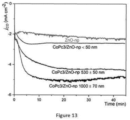
- Electrolysis experiments using electrodes containing several thicknesses of the zinc oxide nano porous MO layers with molecular catalyst 5 were performed in order to assess their catalytic performance, as shown in Figure 13 .
- the TON (Turnover number) for CO formation is calculated upon dividing the mol number of CO formed during electrolysis by the mol number of molecular catalysts at the electrode.
- the TOF (Turnover frequency) for CO formation represents the rate of the catalysis and is calculated upon dividing TON by the electrolysis total time (it is thus an average rate).
- the electrodes After one hour of electrolysis experiments the electrodes have shown high selectivities >90% towards CO production, reaching current densities around -4.6 mA cm -2 with high Faradaic efficiency ⁇ 100%.
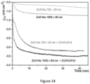
- Electrolysis experiments using zinc oxide nanowires electrodes coated by a zinc oxide nano porous MO 4 thin coating layer with the molecular catalyst 5 were performed in order to assess their catalytic performance, as shown in Figure 14 .
Landscapes
- Chemical & Material Sciences (AREA)
- Organic Chemistry (AREA)
- Engineering & Computer Science (AREA)
- Chemical Kinetics & Catalysis (AREA)
- Electrochemistry (AREA)
- Materials Engineering (AREA)
- Metallurgy (AREA)
- Inorganic Chemistry (AREA)
- Catalysts (AREA)
Abstract
Description
- The invention relates to a porous electrode with a catalytic activity towards CO2 or CO electrochemical and photo-electrochemical reduction.
- In the production of energy, it is reasonable to consider that CO2 emissions will remain high in the next decades. Thus, it appears necessary to find ways to capture CO2 gas, either for storing or valorisation purposes.
- A first solution remains the use of renewable energies, which is becoming more and more common to produce electricity and avoid concomitant production of CO2. A second solution is to perceive CO2 as a source of elements like carbon or oxygen, and not as a waste.
- For example, the promising production of synthetic fuels from CO2 and water has been envisaged. Moreover, CO2 electrochemical reduction to one electron occurs at a very negative potential, thus necessitating a high energy input, and leads to the formation of a highly energetic radical anion. Catalysis thus appears mandatory in order to reduce CO2 and drive the process to multi-electronic and multi-proton reduction process, in order to obtain thermodynamically stable molecules, and with high selectivity.
- Molecular catalysts that combine high selectivity and high current density for CO2 electrochemical reduction to CO or other chemical feedstock are in high demand. Molecular transition metal catalysts offer the distinct advantage of allowing for the fine-tuning of the primary and secondary coordination spheres by manipulating the chelating environment and the steric and electronic effects of the ligands. The ability to improve catalytic efficiency and product selectivity through the rational optimization of the ligand structure is a feature not accessible to the solid-state catalysts common to current pilot-scale electrolyzer units.
- In a document published in 2015, « Synthesis, characterization, and water oxidation by a molecular chromophore-catalyst assembly prepared by atomic layer deposition. The "mummy" strategy, », A. M. Lapides et al. have described a process for preparing multi-component films consisting of molecular light absorbing chromophores and water oxidation catalysts on mesoporous metal oxide surfaces. Atomic layer deposition (ALD) is used to embed a surface-bound chromophore in a thin layer of inert Al2O3. In a final step, catalyst surface-binding is stabilized by a subsequent ALD overlayer of Al2O3. An ALD mummy-based assembly has been used to demonstrate photoelectrochemical dehydrogenation of hydroquinone. The encapsulation is carried out by ALD, i.e. using a gas, which makes the encapsulation more complex. The nature of the metal oxide and the molecular catalyst cannot be changed easily.
- The invention thus proposes to contribute to CO2 emission mitigation by recycling it. The invention proposes active electrodes and photoelectrodes with a catalytic activity towards CO2 reduction and a new way to prepare very active electrodes and photoelectrodes with a catalytic activity towards CO2 reduction. The most important aspect of the invention is the ability to insert and encapsulate with control homogeneous catalysts within structured oxide nanolayers, leading to higher catalytic activity, while using few molecular material and following very simple preparation method. Such an approach may further give additional stability to the catalytic sites and is versatile, the nature of the oxide may indeed be easily tuned as well as the nature of the encapsulated molecular catalyst.
- Here, the invention relates to a porous electrode for electrochemical or photoelectrochemical reduction CO2 or CO comprising:
- a conductive or conductive transparent or photoconductive substrate;
- a conductive nanoporous catalytic matrix on the substrate, which presents a hybrid of a metal oxide MO with nanopores and molecular catalyst which reduce CO2 or CO,
- the conductive nanoporous catalytic matrix being realized by electrodeposition of metal ions from a solvent solution which comprises also solubilized molecular catalyst,
- the conductive nanoporous catalytic matrix comprising a structure of metal oxide MO with nanopores, which encapsulates and integrates homogeneously the molecular catalyst.
- With these arrangements, the catalytic activity is improved compared to the state of the art which does not encapsulate the molecular catalyst in the metal oxide MO layer, and the porous electrode is suitable for electrochemical or photoelectrochemical reduction.
- In various aspects, it is possible to provide for any or all of the following features taken alone or in combination.
- Advantageously, the molecular catalyst is without anchoring group. Thus, there is no need to functionalise the molecular catalyst.
- Advantageously, the conductive nanoporous catalytic matrix is formed by a continuous porous layer of metal oxide MO and the molecular catalyst in the structure of the continuous porous layer. Thus, the active/contact surface of the porous electrode is increased with this porous layer
- In another embodiment, the conductive nanoporous catalytic matrix comprises an array of metal oxide coated nanowires on the surface of the substrate, each metal oxide coated nanowire being a metal oxide nanowire covered by a coating layer of metal oxide with nanopores and molecular catalyst which is in the coating layer. Thus, the surface area of the substrate is increased, which promotes catalytic activity. In addition, the deposition of the porous conductive catalytic matrix is a coating, which means that the shape imparted to the nanowires is retained.
- Advantageously, the porous electrode has a concentration of molecular catalyst equal or superior to 0.5 nmol per cm2 of the porous electrode. Thus, only a small amount of molecular catalyst is required to achieve results with good catalytic activity, and the catalytic activity can be improved by increasing the amount of molecular catalyst encapsulated in the metal oxide structure.
- Advantageously, the porous electrode is presenting optical transmission higher than 60% at wavelengths between 350 and 1300 nm. Thus, the porous electrode is transparent, allowing its use at the surface (on top) of a photoelectrode or allowing to be easily combined to a photoelectrode.
- In another embodiment, the substrate is a photoelectrode comprising:
- a back contact;
- a p-type semiconductor absorber allowing the capture of a large part of the visible solar spectrum;
- a n-type semiconductor for forming a pn junction with the absorber for separation of electrons and holes;
- a top transparent and conductive layer for recovering the electrons formed at the pn junction;
- Thus, the whole system can be used as a photoelectrode allowing the energy produced by the photoelectrode to be used to carry out the reduction of CO2 or CO.
- Advantageously, the molecular catalyst is water-soluble. Thus, the metal oxide can be deposited in an aqueous medium without losing the molecular catalyst encapsulated in the conductive nanoporous catalytic matrix.
- More advantageously, the molecular catalyst is chosen among: metal quaterpyridines, metal porphyrins, metal phthalocyanines or metal corroles, which presents water soluble substituents, with for example metal being Co, Ni, Sn, Cu or Fe. Thus, the catalytic activity of the porous electrode is improved by the use of these molecular catalyst.
- Advantageously, the metal oxide MO is chosen from the following list: aluminum oxide, titanium oxide, or a doped wide band gap metal oxide. More advantageously, the metal oxide MO is zinc oxide. These metal oxides are transparent and can therefore be integrated into photoreduction systems.
- In another embodiment, the invention relates to a process for realizing a porous electrode for CO2 or CO electrochemical or photoelectrochemical reduction on a conductive or conductive transparent or photoconductive substrate, the process comprising the following steps:
- a step a): solubilisation of metal ions, molecular catalyst and an oxygen precursor in a solvent solution;
- a step b): applying a voltage at the substrate in the solvent solution for realizing an electrodeposition of metal ions to form a conductive nanoporous catalytic matrix,
- the growth of the metal oxide MO during the electrodeposition integrating the molecular catalyst,
- the conductive nanoporous catalytic matrix presents a hybrid of metal oxide MO with nanopores, which encapsulates and integrates homogeneously the molecular catalyst.
- With these arrangements, the process allows to obtain porous electrodes which can be an active electrode or photoelectrode with a catalytic activity towards CO2 or CO reduction. The process allows for porous electrodes with improved catalytic activity, while using few molecular material and following simple preparation method. Such an approach may further give additional stability to the catalytic sites and is versatile, since the nature of the oxide may be easily tuned as well as the nature of the encapsulated molecular catalyst.
- In various aspects, it is possible to provide for any or all of the following features taken alone or in combination.
- Advantageously, the solvent solution is a mixture comprising zinc salt such as zinc chloride and the molecular catalyst, the molecular catalyst being water soluble in the solvent solution which is water, and the electrodeposition being realized at a temperature inferior to 100°C.
- The solvent solution for the deposits is water, so it is easy to obtain, it is not expensive and it is a socalled green solvent solution, because the solvent solution is ecological.
- Advantageously, the molecular catalyst is chosen among: metal quaterpyridines, metal porphyrins, metal phthalocyanines or metal corroles, which present water soluble substituents, with for example metal being Co, Ni, Sn, Cu or Fe. Thus, the catalytic activity of the porous electrode is improved by the use of these molecular catalysts.
- Advantageously, the step b) of electrodeposition of the metal ions forms a conductive nanoporous catalytic matrix of metal oxide MO with nanopores, which encapsulates the molecular catalyst, directly on the substrate, to obtain a continuous porous layer.
- In another embodiment, the process comprises a step a0) and a step b0) before the step a):
- a step a0): solubilisation of metal ions and an oxygen precursor in a first solvent solution;
- a step b0): electrodeposition of the metal ions to form nanowires of metal oxide MO on the substrate;
- the step a): solubilisation of the metal ions with molecular catalyst and an oxygen precursor in a second solvent solution;
- the step b): electrodeposition of the metal ions of the second solvent solution to form a conductive nanoporous catalytic matrix of metal oxide MO with nanopores with encapsulated molecular catalyst on the nanowires which are coated by this conductive nanoporous catalytic matrix.
- Thus, the substrate has nanowires on its surface, which increase the effective surface of the electrode. This increases the catalytic activity of the resulting porous electrode.
- Other advantages and characteristics of the disclosed devices and methods will become apparent from reading the description, illustrated by the following figures, where:
-
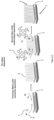
Figure 1 schematically represents the one-step approach used for the material deposition on conductive substrates; -
Figure 2 schematically represents the two-steps approach used for the material deposition on conductive substrates; -
Figure 3a (latera view) andFigure 3b (top view) are SEM images of a flat layer of the prepared conductive nanoporous catalytic matrix being a hybrid of the metal oxide MO and the molecular catalyst; -
Figure 4a andFigure 4b are SEM images of zinc oxide nanowires covered by a conductive nanoporous catalytic matrix being a hybrid of the metal oxide MO and the molecular catalyst; -
Figure 5 represents schematic deposition strategies of the hybrid layers on a conductive support, in this case, zinc oxide nanowires including a molecular catalyst; -
Figure 6 represents schematic deposition strategies of the hybrid layers on a CIGS solar cell, in this case, zinc oxide nanowires including a molecular catalyst; -
Figure 7 represents SEM image of the zinc oxide nanowire deposited during 30 minutes on ZnO:AI window layer on top of a CIGS solar cell; -
Figure 8 represents SEM image of the zinc oxide nanowire deposited during 30 minutes on substrate made of a glass coated with ZnO:Al layer deposited by ALD; -
Figure 9 represents SEM image of the zinc oxide nano porous MO layer with molecular catalyst deposited on ZnO:AI widow layer on top of a CIGS solar cell; -
Figure 10 represents schematic drawing of the experimental setup used for deposition of the hybrid layers; -
Figure 11 represents chronoamperometry registered during an electrolysis at -2.1 V vs. SCE, in CH3CN + 0.1 M TBAPF6 solution saturated with CO2 + 0.6 M H2O as proton source, using electrodes coated with the conductive nanoporous catalytic matrix being a hybrid of the metal oxide MO and the molecular catalyst (CoPc3), with an electrode surface equals to 0.5cm2; -
Figure 12 represents chronoamperometry registered during electrolysis at -1.5 V vs. SCE under illumination AM 1.5 (100 mW.cm-2), in CH3CN + 0.1 M TBAPF6 solution saturated with CO2 + 0.6 M H2O as proton source, using three different electrodes: a CIGS solar cell (Mo/CIGS/CdS/i-ZnO/ZnO:AI), a CIGS solar cell covered with a conductive nanoporous catalytic matrix without catalyst, and a CIGS solar cell covered with a conductive nanoporous catalytic matrix being a hybrid of the metal oxide MO and the molecular catalyst, with an electrode surface equals to 0.5 cm2; -
Figure 13 represents chronoamperometry registered during the electrolysis experiments in a CH3CN + 0.1 M TBAPF6 solution saturated with CO2 + 0.6 M H2O as proton source, using electrodes coated with the conductive nanoporous catalytic matrix being a hybrid of the metal oxide MO and the molecular catalyst (CoPc3) with various thickness, with an electrode surface equals to 0.5 cm2; -
Figure 14 represents chronoamperometry registered during the electrolysis experiments in a CH3CN + 0.1 M TBAPF6 solution saturated with CO2 + 0.6 M H2O as proton source, using electrodes zinc oxide nanowires covered by a conductive nanoporous catalytic matrix being a hybrid of the metal oxide MO and the molecular catalyst, with an electrode surface equals to 0.5 cm2; -
Figures 15 represents the X-ray photoelectron spectroscopy (XPS) analysis of zinc oxide nanowires covered by a conductive nanoporous catalytic matrix being a hybrid of the metal oxide MO and the molecular catalyst, data shows binding energies for cobalt (Co2p); -
Figures 16 represents the X-ray photoelectron spectroscopy (XPS) analysis of zinc oxide nanowires covered by a conductive nanoporous catalytic matrix being a hybrid of the metal oxide MO and the molecular catalyst, data shows binding energies for nitrogen (N1s). - Here is presented, a
porous electrode 1 for electrochemical or photoelectrochemical reduction CO2 or CO, as shown infigure 1 , comprising: - a conductive or conductive transparent or
photoconductive substrate - a conductive nanoporous
catalytic matrix 3 on thesubstrate metal oxide MO 4 with nanopores andmolecular catalyst 5 which reduce CO or CO2, - the conductive nanoporous
catalytic matrix 3 being realized by electrodeposition of metal ions from a solvent solution which comprises also solubilizedmolecular catalyst 5, - the conductive nanoporous
catalytic matrix 3 comprising a structure ofmetal oxide MO 4 with nanopores, which encapsulates and integrates homogeneously themolecular catalyst 5. - Advantageously, there is a growth of the
metal oxide MO 4 during the electrodeposition forming a structure ofmetal oxide MO 4 with nanopores and integrating themolecular catalyst 5. - Advantageously, the molecular catalyst is in the structure of the
metal oxide MO 4 and in the nanopores. - Advantageously, the conductive nanoporous
catalytic matrix 3 is on thesubstrate metal oxide MO 4 and amolecular catalyst 5, realized by electrodeposition, comprisingmetal oxide MO 4 with nanopores, which encapsulates the metalmolecular catalyst 5, the nanopores of themetal oxide MO 4 being formed during the electrodeposition. - Advantageously, the conductive nanoporous
catalytic matrix 3, being a hybrid of ametal oxide MO 4 and amolecular catalyst 5 because themetal oxide MO 4 encapsulates the metalmolecular catalyst 5, allows catalytic activity on the entire surface of the substrate. In addition, themolecular catalyst 5 remains in the conductive nanoporouscatalytic matrix 3 without having been functionalized previously. - In the present invention, the term "homogeneously" defines that the
molecular catalyst 5 is uniformly distributed throughout theporous electrode 1 without forming aggregates. - In the present invention, the term "hybrid" means that the conductive nanoporous
catalytic matrix 3 is composed of disparate elements, a mixture. - Advantageously, a catalytic activity coming from the
molecular catalyst 5 in the structure. - The
porous electrode 1 can be transparent. Advantageously, theporous electrode 1 is transparent in the visible and near infrared range. Advantageously, theporous electrode 1 is presenting optical transmission higher than 60% at wavelengths between 250 and 1500 nm, more advantageously between 300 and 1450 nm, 350 and 1400 nm, 400 and 1350 nm or 450 and 1300 nm. - Thus, the
porous electrode 1 can be used on solar cells. - Advantageously, the optical transmission is higher than 65%, 70%, 75%, 80%, 85%, 90% or 95%, for all the previous wavelength ranges.
- Advantageously, all components of the
porous electrode 1 have an optical transmission higher than 60% at wavelengths at least between 350 and 1300 nm. - The transparency of the components allows the visible light to pass through the nano porous or nanowire electrode for photoelectrochemical reduction.
- Advantageously, the
substrate 2 is photoconductive 2b or conductive or transparent and conductive 2a. - The
substrate 2 may have a particular shape and/or surface structure. The surface structure may be porous, micro-structured, or nano-structured. Thesubstrate 2 may have nanowires on its surface, or another nanostructure that increases the active surface (the contact area). - Advantageously, the
substrate 2 is anelectrode 2a or aphotoelectrode 2b. - The
substrate 2 can be aphotoelectrode 2b comprising: - a back contact;
- a p-type semiconductor absorber allowing the capture of a large part of the visible solar spectrum;
- a n-type semiconductor for forming a pn junction with the absorber for separation between electrons and holes;
- a top contact transparent and conductive layer for recovering the electrons formed at the pn junction.
- Advantageously, the
photoelectrode 2b is a simple or multijunction solar cell. - Advantageously, the
substrate 2 comprises at least a metal oxide conductive top layer. - The metal oxide conductive top layer can be an aluminium doped zinc oxide, tin doped indium oxide (ITO), fluorine doped tin oxide (SnO2:F). Advantageously, the thickness of the top layer is superior to 10 nm.
- Advantageously, the conductive nanoporous
catalytic matrix 3 is a hybrid of ametal oxide MO 4 and amolecular catalyst 5, realized by electrodeposition, comprising ametal oxide MO 4 which encapsulates the metalmolecular catalyst 5 in the structure. - The conductive nanoporous
catalytic matrix 3 is on thesubstrate 2. - Within the meaning of the present invention, the terms "the conductive nanoporous catalytic matrix" 3 can also be called indifferently: "nanostructured hybrid oxide layer for CO2 or CO reduction", "nanostructured catalytic material", or "porous catalytic nanostructures".
- The density and size of the nanopores depends on shape, size or type of
molecular catalyst 5, the nanopores ofmetal oxide MO 4 are formed during the electrodeposition. - Thus, the density and/or size of the nanopores can be modified by changing the molecular catalyst.
- Advantageously, the conductive nanoporous
catalytic matrix 3 is transparent. - Advantageously, the conductive nanoporous
catalytic matrix 3 is formed by mixing of themetal oxide MO 4 and themolecular catalyst 5. - Advantageously, the conductive nanoporous
catalytic matrix 3 is formed by a continuous porous layer ofmetal oxide MO 4 and themolecular catalyst 5. - Advantageously, the conductive nanoporous
catalytic matrix 3 is formed by a continuous porous layer ofmetal oxide MO 4 and themolecular catalyst 5 in the structure of the continuous porous layer. - Advantageously, the continuous porous layer has a thickness inferior to 1 micrometre.
- Thus, this thickness allows a good catalytic rate to be maintained by the transport phenomena in the conductive nanoporous catalytic matrix 3 (charge transport and CO2 or CO and/or proton transport).
- In the present invention, the term "continuous porous" means that the layer comprising the
metal oxide MO 4 structure covers thesubstrate - In another embodiment, the conductive nanoporous
catalytic matrix 3 comprises an array of metal oxide coatednanowires 6 on the surface of thesubstrate nanowire 6 being a metal oxide nanowire covered by a coating layer ofmetal oxide MO 4 with nanopores andmolecular catalyst 5 which is in the coating layer, as shown inFigures 2 ,4a ,4b ,6 ,7 and 8 . - The term "coating layer" means that said layer is a coating, the shape of the
substrate 2 is preserved during the deposition of this coating, so the coating layer increases the thickness of theporous electrode 1 on the whole surface. - Advantageously, these layers can be deposited on top of a
conductive electrode solar cells 2b such as a copper indium gallium selenide solar cell (CIGS). - Advantageously, the coating layer having a thickness inferior to 50 nanometres.
- This thickness allows the structure of the
substrate 2 and the shape of thenanowires 6 to be maintained. - Advantageously, the
nanowires 6 present a ratio length /diameter superior or equal to 1. More advantageously, the ratio thickness/diameter is superior to 2, 3, 4, 5, 6, 7, 8, 9 or 10. - In the present invention, the thickness of the nanowires is the distance between the substrate (the base) and the tip of the nanowires.
- In another embodiment, the conductive nanoporous
catalytic matrix 3 is covered by a layer of anothermetal oxide 4. The additional layer protects theporous electrode 1 from corrosion of the electrolyte. - For example, the additional layer is SnO2, TiO2, or Al2O3.
- Advantageously, during the formation of the
porous metal oxide 4 structure, themolecular catalyst 5 is integrated and encapsulated in said porous structure. Themolecular catalyst 5 is embedded in the metal oxide structure and may also be in the nanopores of said porous layer. - The
metal catalyst 5 may be both in the bulk (volume of the layer) of the metal oxide and in the nanopores, due to co-deposition. - Advantageously, the
molecular catalyst 5 is soluble in the solution used for electrodeposition. More advantageously, themolecular catalyst 5 is water-soluble. Advantageously, the encapsulated water-soluble molecular catalyst in the conductive nanoporouscatalytic matrix 3 is maintained in the conductive nanoporouscatalytic matrix 3 even when in contact with an aqueous solution. - In the present invention, the porosity of the conductive nanoporous catalytic electrode allows the molecular catalyst to be in contact with the electrolyte solution and with the CO2 and CO gases to be reduced. The porosity also allows the release of the CO2 and CO once reduced.
- Advantageously, the
molecular catalyst 5 has a core with an earth-abundant transition metal such as Fe, Mn, Co, Ni, Sn, Cu or rare metals such as Ruthenium, Rhenium, Gold, Silver. - More advantageously, the
molecular catalyst 5 is chosen among: metal quaterpyridines, metal porphyrins, metal corroles or metal phthalocyanines, which present water soluble substituents with for example metal being Co, Ni, Sn, Cu or Fe. - In another embodiment, the
molecular catalyst 5 is chosen to reduce: - selectively CO2 to CO; or
- selectively CO2 to an alcohol, such as methanol; or
- selectively CO2 to formaldehyde; or
- selectively CO2 to methane; or
- selectively CO2 to multi-carbon molecules such as ethanol, ethylene.
- In another embodiment, the
molecular catalyst 5 is chosen to reduce: - selectively CO to an alcohol, such as methanol; or
- selectively CO to formaldehyde; or
- selectively CO to methane; or
- selectively CO to multi-carbon molecules such as ethanol, ethylene.
- Advantageously, the
molecular catalyst 5 is without functions to fix it to themetal oxide MO 4 in the conductive nanoporouscatalytic matrix 3. - Advantageously, the
molecular catalyst 5 is without anchoring group. - Thus, the
molecular catalyst 5 is not deposited using carboxylates, phosphonates, organosilanes, hydroxamates, and acetylacetonates functions that are usually appended to the ligand of the molecular catalyst s for immobilization onmetal oxide 4 surfaces. - Advantageously, the reduction of CO2 or CO produces a selective product, the selective product depends on the
molecular catalyst 5. - Advantageously, the
porous electrode 1 has a concentration ofmolecular catalyst 5 equal or superior to 0.5 nmol per cm2 of theporous electrode 1. More advantageously, the concentration of molecular catalyst in the structure is superior to 1 nmol /cm2, 2 nmol /cm2, 3 nmol /cm2, 4 nmol /cm2, 5 nmol /cm2, 6 nmol /cm2, or 7 nmol /cm2 of theporous electrode 1. - In the present invention, the
porous electrode 1 has catalytic activity despite the low amount ofmolecular catalyst 5, furthermore the catalytic activity can be improved by increasing the amount ofmolecular catalyst 5. - Advantageously, the
metal oxide MO 4 is chosen from the following list: aluminium oxide, titanium oxide, or a doped wide band gap metal oxide film. More advantageously, themetal oxide MO 4 is zinc oxide (ZnO). - Advantageously, the doped wide band gap metal oxide film has Eg > 2.4 eV.
- For example, ZnO presents remarkable properties that make it a good candidate for preparing a photoelectrode. It is transparent thanks to its wide bandgap (3.2 eV) and has controllable properties of conductivity depending on the doping level. Moreover, ZnO, in contrast to many other wide bandgap semiconductors, has the unique advantage that it can be easily prepared in high quality by solution routes. This allows low-temperature (mostly <100°C) cost-effective deposition processes, and the solution environment can be used to promote highly selective self-assembly to generate structures ranging from dense thin films to nanostructures.
- Advantageously, a combination of the
metal oxide MO 4 and themolecular catalyst 5 is chosen to improve the catalytic activity. For example, ZnO with CoPc3. - In another embodiment, the invention relates to a process for realizing a
porous electrode 1 for CO2 or CO electrochemical or photoelectrochemical reduction on a conductive or conductive transparent orphotoconductive substrate - a step a): solubilisation of metal ions,
molecular catalyst 5, and anoxygen precursor 7 in a solvent solution; - a step b): applying a voltage at the
substrate catalytic matrix 3, - the growth of the
metal oxide MO 4 during the electrodeposition integrating themolecular catalyst 5, - the conductive nanoporous
catalytic matrix 3 presents a hybrid of metal oxide MO (4) with nanopores, which encapsulates and integrates homogeneously themolecular catalyst 5. - Advantageously, the electrodeposition causes an encapsulation of the
molecular catalyst 5 in the metal oxide structure, the conductive nanoporouscatalytic matrix 3 being a hybrid of themetal oxide MO 4 and themolecular catalyst 5, which reduces CO2 or CO due to the catalytic properties of the encapsulatedmolecular catalyst 5. - Within the meaning of the present invention, the process can also be called "a
molecular catalyst 5 encapsulation" or "one-step deposition", as show in the figures. - This way of incorporating a
molecular catalyst 5 into the conductive nanoporouscatalytic matrix 3 allows to: use small quantities of non-functionalized catalyst as compared to other preparation methods, incorporate themolecular catalyst 5 homogeneously in themetal oxide 4, improve the catalytic activity of the molecule itself and keep the high selectivity of themolecular catalyst 5. - Advantageously, electrodeposition allows a metal oxide/molecular catalyst co-deposit to be made. Thus, the advantage is that the molecular catalyst remains accessible through the porosity of the material (of the deposited metal oxide layer). However, electrodeposition is a simple, one-step method that can be done at low temperatures < 100 °C and over a large area.
- Advantageously, the
substrate 2 is conductive 2b or transparent and conductive 2a. - The
substrate 2 may have a particular shape and/or surface structure. The surface structure may be porous, micro structured, or nano structured. Thesubstrate 2 may have nanowires on its surface, or another nanostructure that increases the active surface (contact area). - Advantageously, the
substrate 2 is anelectrode 2a or aphotoelectrode 2b, as shown inFigure 9 . - The
substrate 2 can be aphotoelectrode 2b comprising: - a back contact;
- a p-type semiconductor absorber allowing the capture of a large part of the visible solar spectrum;
- a n-type semiconductor for forming a pn junction with the absorber for separation between electrons and holes;
- a top contact transparent and conductive layer for recovering the electrons formed at the pn junction.
- Advantageously, the
photoelectrode 2b is a simple or multijunction solar cell. - Advantageously, the
substrate 2 comprises at least a metal oxide conductive top layer. - The metal oxide conductive outer layer can be an aluminium doped zinc oxide (AZO), tin doped indium oxide (lnO2:Sn, ITO), fluorine doped tin oxide (SnO2:F) or any other transparent conductive oxides. Advantageously, the thickness of the top layer is larger than 10 nm.
- For example, the
substrate 2a has an aluminium doped zinc oxide (AZO) conductive layer of 380 nm thick with sheet resistance from 20.1 to 28.2 × 10⁻³ Ω/sq, deposited by Atomic Layer Deposition (ALD), on aglass substrate 2 mm thick. - Advantageously, the
substrate 2a was ultrasonically sequentially cleaned in acetone, 2-propanol, and water each for 5 min, before the whole process. - Advantageously, the
substrate 2a was activated in a KOH solution pH 10.5 for 2 min and finally rinsed with distilled water prior the electrodeposition. - Advantageously, the
substrate 2b was rinsed with 2-propanol and distilled water then activated in a KOH solution pH 10.5 for 2 min and finally rinsed with distilled water prior the electrodeposition. - The process is carried out on a
substrate 2 with one or a combination of the following: - conductive or transparent and conductive electrode;
- an electrode or a photoelectrode;
- a photoelectrode comprising:
- a back contact;
- a p-type semiconductor absorber allowing the capture of a large part of the visible solar spectrum;
- a n-type semiconductor for forming a pn junction with the absorber for separation between electrons and holes;
- a top contact transparent and conductive layer for recovering the electrons formed at the pn junction;
- a simple or multi-junction solar cell;
- a substrate comprising at least a metal oxide conductive top layer.
- Advantageously, the reduction of CO2 or CO produces a selective product, the selective product depends on the
molecular catalyst 5. - Advantageously, in the step a) of metal ions solubilisation in a solvent solution, the solvent solution contains also a
molecular catalyst 5 and anoxygen precursor 7. - According to various embodiments, the metal ions can be Zn2+, Al3+, Ti2+.
- Advantageously, the solvent solution is a water mixture comprising zinc salt such as zinc chloride and the
molecular catalyst 5 being water soluble in the solvent solution which is water, and the electrodeposition being realized at a temperature inferior to 100°C. The zinc salt can be chloride or nitrate. - More advantageously, the solvent solution comprises an
oxygen precursor 7 such as oxygen from the air. The solvent solution can contain nitrates or oxygenated water. - For example, the method for ZnO electrodeposition is to form an excess of hydroxide ions through the reduction of an oxygen precursor, such as oxygen, nitrate ions, or peroxide species. By using chloride and oxygen precursor, the deposition can be done in a pH range from 5 to 7.
- Advantageously, the solvent solution is a mixture of zinc chloride, potassium chloride, oxygen and the
molecular catalyst 5. - For example, the solvent solution is an aqueous solution of 5 mM ZnCl2, 0.1 M KCl, 0-8.10-4 M of dissolved O2, and 50 µM of a Cobalt phthalocyanine molecule (CoPc3) bearing four trimethylammonium groups.
- Thus, the Cl- ions in the solution will promote doping of the zinc oxide catalytic matrix, which ensures that the deposited oxide is conductive.
- The
molecular catalyst 5 is in the nanopores of the conductive nanoporouscatalytic matrix 3 for CO2 or CO reduction. - Advantageously, the
molecular catalyst 5 is water-soluble. More advantageously, themolecular catalyst 5 includes an earth-abundant metal. - Advantageously, the
molecular catalyst 5 is chosen among: metal quaterpyridines, metal porphyrins, metal phthalocyanines or metal corroles, which presents water soluble substituents, with for example metal being Co, Ni, Sn, Cu or Fe. - For example, the
molecular catalyst 5 is Cobalt phthalocyanine molecule (CoPc3) bearing four trimethylammonium groups. - Advantageously, the concentration of
molecular catalyst 5 used is inferior to 10 nmol/cm2, more advantageously, inferior to 9 nmol/cm2, 8 nmol/cm2, 7 nmol/cm2, 6 nmol/cm2, 5 nmol/cm2, or 4 nmol/cm2. - In another embodiment, the
molecular catalyst 5 is chosen to reduce: - selectively CO2 to CO; or
- selectively CO2 to an alcohol, such as methanol; or
- selectively CO2 to formaldehyde; or
- selectively CO2 to methane; or
- selectively CO2 to multi-carbon molecules such as ethanol, ethylene.
- In another embodiment, the
molecular catalyst 5 is chosen to reduce: - selectively CO to an alcohol, such as methanol; or
- selectively CO to formaldehyde; or
- selectively CO to methane; or
- selectively CO to multi-carbon molecules such as ethanol, ethylene.
- The step b) of the process is an electrodeposition of the metal ions to form the conductive nanoporous
catalytic matrix 3 ofmetal oxide MO 4 on a conductive or conductive transparent orphotoconductive substrate - Advantageously, the electrodeposition is made at a given potential and a given temperature.
- Advantageously, the given potential is comprised between -0.8 and -1.4 V vs SCE, more advantageously between -0.9 and -1.3, or -1.0 and -1.2 V vs SCE.
- During the formation of the conductive nanoporous
catalytic matrix 3, the metal ions contained in the solvent solution are attracted to the substrate and deposited on its surface. During the deposition, the molecular catalyst contained also in the solvent solution is encapsulated in the formed layer. - Advantageously, the step b) of electrodeposition of the metal ions forms a conductive nanoporous
catalytic matrix 3 ofmetal oxide MO 4 with nanopores, which encapsulates the molecular catalyst, directly on thesubstrate - For example, the realization of the conductive nanoporous
catalytic matrix 3 was carried out potentiostatically at -1.0 V vs SCE in an aqueous solution, 5 mM ZnCl2, 0.1 M KCI, 0-8.10-4 M O2 dissolved and 50 µM of a Cobalt phthalocyanine molecule (CoPc3) bearing four trimethylammonium groups In another embodiment, the process comprises a step a0) and a step b0), before the step a): - a step a0): solubilisation of metal ions and an oxygen precursor 7in a first solvent solution;
- a step b0): electrodeposition of the metal ions to form nanowires (6) of
metal oxide MO 4 on thesubstrate - the step a): solubilisation of the metal ions with
molecular catalyst 5 and anoxygen precursor 7 in a second solvent solution; - the step b): electrodeposition of the
metal ions 5 of the second solvent solution to form a conductive nanoporouscatalytic matrix 3 ofmetal oxide MO 4 with nanopores with encapsulated molecular catalyst on thenanowires 6 which are coated by this conductive nanoporouscatalytic matrix 3. - Within the meaning of the present invention, the process comprising the realization of
nanowires 6 ofmetal oxide MO 4, is also called "two-steps deposition", as shown in the figures. - Thus, the
substrate 2 has a nanostructure on its surface, such asnanowires 6, as shown inFigures 5, 6 ,7 and 8 . - The
nanowires 6 can also be deposited on aphotocathode 2b, as shown inFigures 6 and7 . - Advantageously, the electrodeposition of the metal ions has a given potential and a given temperature.
- Advantageously, the given potential is comprised between -0.4 and -1.4 V vs SCE, more advantageously between -0.9 and -1.3, or -1.0 and -1.2 V vs SCE.
- Advantageously, the given temperature is comprised between 40°C and 100°C, more advantageously between 50°C and 90°C, or 60°C and 80°C.
- Advantageously, the
nanowires 6 and the conductive nanoporouscatalytic matrix 3 were electrodeposited using a three electrodes setup, as shown inFigure 10 . - A schematic drawing of the experimental setup is presented in
Figure 10 . For example, the reference electrode is a Saturated Calomel Electrode (SCE) with a potential of +0.244 V vs. SHE at 25 °C. The counter electrode is a platinum wire cleaned ultrasonically prior electrodeposition. Working electrodes are the mentioned ZnO:Al/glass (transparent conductive electrode) or the CIGS solar cell electrode (photoelectrode). - Advantageously, the first solvent solution being a mixture of zinc chloride, potassium chloride and soluble oxygen.
- For example, the deposition of this
nanowire 6 array was carried out potentiostatically at -1.4 V vs SCE in an aqueous solution, 0.2 mM ZnCl2, 0.1 M KCI maintained at 80°C. - Advantageously, the second solvent solution is a water mixture comprising zinc salt such as zinc chloride and the
molecular catalyst 5 being water soluble in the solvent solution which is water, and the electrodeposition being realized at a temperature inferior to 100°C. The zinc salt can be chloride or nitrate. - More advantageously, the second solvent solution comprises an
oxygen precursor 7 such as oxygen from the air. The solvent solution can contain nitrates or oxygenated water. - For example, the method for ZnO electrodeposition is to form an excess of hydroxide ions through the reduction of an oxygen precursor, such as oxygen, nitrate ions, or peroxide species. By using chloride and oxygen precursor, the deposition can be done in a pH range from 5 to 7.
- Advantageously, the second solvent solution is a mixture of zinc chloride, potassium chloride, oxygen and the
molecular catalyst 5. - For example, the second solvent solution is an aqueous solution of 5 mM ZnCl2, 0.1 M KCI, 0-8.10-4 M of dissolved O2, and 50 µM of a Cobalt phthalocyanine molecule (CoPc3) bearing four trimethylammonium groups.
- Advantageously, the
substrate 2 withnanowires 6 is rinsed with water and dried in air at 100°C before the step a). - Advantageously, the conductive nanoporous
catalytic matrix 3 is realized by electrodeposition, with conditions for controlling: - diameter and thickness or height of the
nanowires 6; and - diameter and thickness or height of the conductive nanoporous
catalytic matrix 3 which rest on thecoated nanowires 6. - For example, in the case of the
nanowires 6, the temperature affects the solubility of theoxygen precursor 7. The solubility ofoxygen precursor 7 decreases as the solution temperature increases which significantly reduces the kinetics for the formation of thenanowires 6. However, the crystallinity of the deposited films increases as the solution temperature increases. Optimal temperatures range from 60 to 85°C. The applied potential affects the preferred orientation of thenanowires 6. The diameter and density ofnanowires 6 increase as the potential applied increased. The metal ions concentration affects the diameter and thenanowire 6 density. The thickness of thenanowires 6 is controlled by measuring the charge being transferred during the electrodeposition process, thus it is directly correlated to the deposition time. - For example, in the case of the conductive nanoporous
catalytic matrix 3, the thickness of thecatalytic matrix 3 is controlled by measuring the charge being transferred during the electrodeposition process, thus it is directly correlated to the deposition time. The applied potential affects the molecular catalyst loading. The amount of molecular catalyst into the films increases with more negative potentials. - Advantageously, oxygen gas being bubbled for 20 min prior to the step a) and the step b), and the same gas flow was maintained during the whole deposition process.
- Advantageously, the solution being stirred at 800 rpm.
- The invention relates to a porous electrode used in CO2 or CO reduction, the selectivity of the
porous electrode 1 depending on themolecular catalyst 5 used. - In another embodiment, depending on the use of the
porous electrode 1, themolecular catalyst 5 is chosen to reduce: - selectively CO2 to CO; or
- selectively CO2 to an alcohol, such as methanol; or
- selectively CO2 to formaldehyde; or
- selectively CO2 to methane; or
- selectively CO2 to multi-carbon molecules such as ethanol, ethylene.
- In another embodiment, depending on the use of the
porous electrode 1, themolecular catalyst 5 is chosen to reduce: - selectively CO to an alcohol, such as methanol; or
- selectively CO to formaldehyde; or
- selectively CO to methane; or
- selectively CO to multi-carbon molecules such as ethanol, ethylene.
- For example, the following
molecular catalyst 5 was used:
- For example, the
porous electrodes 1 with the conductive nanoporouscatalytic matrix 3 were used for the electrochemical reduction of CO2 in acetonitrile adding 0.1 M of Tetrabutylammonium hexafluorophosphate (NBu4PF6) salt as supporting electrolyte, using electrodes with a surface of 0.5 cm2. The results of these experiments show that the conductive nanoporouscatalytic matrix 3 is electrochemically active to perform CO2 reduction to CO. - For example, the prepared ZnO:AI (AZO) electrodes with the hierarchical structures have shown current densities up to 3.5 mA cm-2 during electrolysis experiments at an applied potential of -2.1 V vs. SCE, as shown in
figure 11 . In terms of efficiency and selectivity, the porous electrodes present high Faradaic efficiencies and high selectivity of ca. 90% toward CO formation. Such high selectivity and current result from the combination of conductive nanoporouscatalytic matrix 3 with themolecular catalyst 5 and could not be obtained from the use of individual components (oxide or molecular catalyst alone). - Based on these encouraging results, these conductive
porous matrices 3 have been integrated to standard CIGSsolar cell photoelectrodes 2b. The performance of these electrodes towards CO2 reduction reaction has been studied. A standard CIGS solar cell is compared to solar cells with the conductive nanoporouscatalytic matrix 3 withoutmolecular catalyst 5, and with a combination of conductive nanoporouscatalytic matrix 3 and themolecular catalyst 5. Controlled-potential photoelectrolysis experiments in acetonitrile 0.1 M TBAPF6 solution have confirmed the photoreduction of CO2, as shown infigure 12 . The photoelectrolysis experiments with a CIGS electrode covered with a conductive nanoporouscatalytic matrix 3, maintained at a potential of -1.5 V vs. SCE with front illumination AM1.5G (100 mW cm-2) produced CO with a total FE and selectivity of ca. 95%. A high current density with a mean value of 4.2 mA cm-2 was obtained during a one-hour electrolysis experiment. From the deposited layers, we may note an improved catalytic effect from the conductive nanoporouscatalytic matrix 3 withoutmolecular catalyst 5 as compared to the 'standard' CIGS solar cells with good selectivity and high faradaic efficiencies. The addition of themolecular catalyst 5 led to the highest catalytic activity suggesting a combination of catalytic effects of themetal oxide 4 andmolecular catalyst 5. - For example, the following
molecular catalyst 5 can be used in the porous electrode 1: - Quaterpyridine metal complexes:

- Phthalocyanine metal complexes:

- Porphyrin metal complexes:


- Corrole metal complexes :

- Electrolysis experiments using electrodes containing several thicknesses of the zinc oxide nano porous MO layers with
molecular catalyst 5 were performed in order to assess their catalytic performance, as shown inFigure 13 . - The table below shows the summary of results obtained from the analysis of the gas product generated during the electrolysis experiments using electrodes with various thickness of the conductive nanoporous
catalytic matrix 3 of ZnO containing themolecular catalyst 5.Conductive nanoporous catalytic matrix thickness Catalyst Concentratio n (nmol/cm2) J (mA.cm-2) Faradaic Efficiency Selectivity TON for CO TOF for CO (s-1) FE CO FE H2 FE total CO H2 ZnO-Nano porous 1000 ± 100 nm 0.0 -2.5 85.1% 9.0% 94.1% 89.9% 10.1% ZnO-Nano porous /catalyst < 50nm 0.6 -2.8 103.2 % 2.6% 105.8 % 97.5% 2.5% 19100 15.9 ZnO-Nano porous /catalyst 500 ± 50 nm 2.7 -3.5 100.9 % 1.6% 102.5 % 98.4% 1.6% 4723 3.2 ZnO-Nano porous / catalyst 1000 ± 70 nm3.4 -4.6 96.1% 1.1% 97.3% 98.8% 1.2% 8713 4.5 - In the present invention, the TON (Turnover number) for CO formation is calculated upon dividing the mol number of CO formed during electrolysis by the mol number of molecular catalysts at the electrode. The TOF (Turnover frequency) for CO formation represents the rate of the catalysis and is calculated upon dividing TON by the electrolysis total time (it is thus an average rate).
- After one hour of electrolysis experiments the electrodes have shown high selectivities >90% towards CO production, reaching current densities around -4.6 mA cm-2 with high Faradaic efficiency ≈ 100%.
- Electrolysis experiments using zinc oxide nanowires electrodes coated by a zinc oxide nano
porous MO 4 thin coating layer with themolecular catalyst 5 were performed in order to assess their catalytic performance, as shown inFigure 14 . - The table below summarizes the results obtained from the analysis of the gas product generated during the electrolysis experiments using zinc oxide nanowires electrodes coated by a zinc oxide nano
porous MO 4 thin coating layer with themolecular catalyst 5.ZnO nanowires covered with ZnO-Nano porous /catalyst thickness Catalyst concentration (nmol.cm-2) Average j (mA.cm-2) Faradaic Efficiency Selectivity TON for CO TOF for CO (s-1) FE CO FE H2 FE total CO H2 ZnO- nw 700 + 50 nm0.69 -2.45 106.7% 6.46% 113.2% 94.3% 5.7% 11848 6.6 ZnO- nw 1000 ± 80 nm0.73 -3.40 86.7% 2.7% 89.4% 97.0% 3.0% 19258 8 - After one hour of electrolysis experiments the electrodes have shown high selectivity >90% towards CO production, with current density values that increase when the thickness of the
nanowires 6 is increased. Current density values ca. -3.5 mA cm-2 were reached in samples with a small quantity of the molecular catalyst 5 (0.73 nmol cm-2). - As shown in
figure 15 from the XPS analysis, two peaks were observed for the cobalt (Co2p) at binding energies of 795.5 and 780.5 eV respectively, confirming the presence of the cobalt metallic center of the molecular catalyst at the surface of the zinc oxide nanowires. The blank response of the zinc oxide nanowires without the hybrid layer of MO and the molecular catalyst is also shown, no peak being observed in this energy range. - As shown in
figure 16 from the XPS analysis, three peaks were observed for the Nitrogen (N1s) at binding energies of 402.7, 398.7 and 400.3 eV respectively, confirming the presence of the nitrogen atoms of the molecular catalyst (ligand) at the surface of zinc oxide nanowires. The blank response of the zinc oxide nanowires without the hybrid layer of MO and the molecular catalyst is also shown, no peak being observed in this energy range.
Claims (16)
- Porous electrode (1) for electrochemical or photoelectrochemical reduction of CO2 or CO characterized by:- a conductive or conductive transparent or photoconductive substrate (2, 2a, 2b);- a conductive nanoporous catalytic matrix (3) on the substrate (2, 2a, 2b), which presents a hybrid of a metal oxide MO (4) with nanopores and molecular catalyst (5) which reduce CO2 or CO,the conductive nanoporous catalytic matrix (3) being realized by electrodeposition of metal ions from a solvent solution which comprises also solubilized molecular catalyst (5),the conductive nanoporous catalytic matrix (3) comprising a structure of metal oxide MO (4) with nanopores, which encapsulates and integrates homogeneously the molecular catalyst (5).
- Porous electrode (1) according to claim 1, wherein the molecular catalyst (5) is without anchoring group.
- Porous electrode (1) according to claims 1 or 2, wherein the conductive nanoporous catalytic matrix (3) is formed by a continuous porous layer of metal oxide MO (4) and the molecular catalyst (5) in the structure of the continuous porous layer.
- Porous electrode (1) according to claims 1 or 2, wherein the conductive nanoporous catalytic matrix (3) comprises an array of metal oxide coated nanowires (6) on the surface of the substrate (2, 2a, 2b), each metal oxide coated nanowire (6) being a metal oxide nanowire covered by a coating layer of metal oxide MO (4) with nanopores and molecular catalyst (5) which is in the coating layer.
- Porous electrode (1) according to one of claims 1 to 4, wherein the porous electrode (1) has a concentration of molecular catalyst (5) equal or superior to 0.5 nanomole per cm2 of the substrate (2, 2a, 2b).
- Porous electrode (1) according to one of claims 1 to 5, wherein the porous electrode (1) is presenting optical transmission higher than 60% at wavelengths between 350 and 1300 nm.
- Porous electrode (1) according to one of claims 1 to 6, wherein the substrate (2) is a photoelectrode (2b) comprising:- a back contact;- a p-type semiconductor absorber allowing the capture of a large part of the visible solar spectrum;- a n-type semiconductor for forming a pn junction with the absorber for separation of electrons and holes;- a top contact transparent and conductive layer for recovering the electrons formed at the pn junction;advantageously, the photoelectrode (2b) is a simple or multijunction solar cell.
- Porous electrode (1) according to one of claims 1 to 7, wherein the molecular catalyst (5) is water-soluble.
- Porous electrode (1) according to one of claims 1 to 8, wherein the molecular catalyst (5) is chosen among: metal quaterpyridines, metal porphyrins, metal phthalocyanines or metal corroles, which presents water soluble substituents, with for example metal being Co, Ni, Sn, Cu or Fe.
- Porous electrode (1) according to one of claims 1 to 9, wherein the metal oxide MO (4) is chosen from the following list: aluminum oxide, titanium oxide, or a doped wide band gap metal oxide.
- Porous electrode (1) according to one of claims 1 to 10, wherein the metal oxide MO (4) is zinc oxide.
- Process for realizing a porous electrode (1) for CO or CO2 electrochemical or photoelectrochemical reduction on a conductive or conductive transparent or photoconductive substrate (2, 2a, 2b), according to one of claims 1 to 11,
the process comprising the following steps:- a step a): solubilisation of metal ions, molecular catalyst (5), and an oxygen precursor (7) in a solvent solution;- a step b): applying a voltage at the substrate (2, 2a, 2b) in the solvent solution for realizing an electrodeposition of metal ions, to form a conductive nanoporous catalytic matrix (3), the growth of the metal oxide MO (4) during the electrodeposition integrating the molecular catalyst (5),the conductive nanoporous catalytic matrix (3) presents a hybrid of metal oxide MO (4) with nanopores, which encapsulates and integrates homogeneously the molecular catalyst (5). - Process according to claim 12, wherein the solvent solution is a mixture comprising zinc salt such as zinc chloride and the molecular catalyst (5), the molecular catalyst (5) being water soluble in the solvent solution which is water, and the electrodeposition being realized at a temperature inferior to 100°C.
- Process according to claims 12 or 13, wherein the molecular catalyst (5) is chosen among: metal quaterpyridines, metal porphyrins, metal phthalocyanines or metal corroles, which present water soluble substituents, with for example metal being Co, Ni, Sn, Cu or Fe.
- Process according to one of claims 12 to 14, wherein the step b) of electrodeposition of the metal ions forms a conductive nanoporous catalytic matrix (3) of metal oxide MO (4) with nanopores, which encapsulates the molecular catalyst, directly on the substrate (2, 2a, 2b), to obtain a continuous porous layer.
- Process according to one of claims 12 to 14, wherein the process comprises a step a0) and a step b0), before the step a):- a step a0): solubilisation of metal ions and an oxygen precursor (7) in a first solvent solution;- a step b0): electrodeposition of the metal ions to form nanowires (6) of metal oxide MO (4) on the substrate (2, 2a, 2b);- the step a): solubilisation of the metal ions with molecular catalyst (5) and an oxygen precursor (7) in a second solvent solution;- the step b): electrodeposition of the metal ions (5) of the second solvent solution to form the conductive nanoporous catalytic matrix (3) of metal oxide MO (4) with nanopores with encapsulated molecular catalyst on the nanowires (6) which are coated by this conductive nanoporous catalytic matrix (3).
Priority Applications (1)
| Application Number | Priority Date | Filing Date | Title |
|---|---|---|---|
| EP22156106.1A EP4227441A1 (en) | 2022-02-10 | 2022-02-10 | Porous electrode with a catalytic activity towards co2 or co electrochemical and photo-electrochemical reduction |
Applications Claiming Priority (1)
| Application Number | Priority Date | Filing Date | Title |
|---|---|---|---|
| EP22156106.1A EP4227441A1 (en) | 2022-02-10 | 2022-02-10 | Porous electrode with a catalytic activity towards co2 or co electrochemical and photo-electrochemical reduction |
Publications (1)
| Publication Number | Publication Date |
|---|---|
| EP4227441A1 true EP4227441A1 (en) | 2023-08-16 |
Family
ID=80447616
Family Applications (1)
| Application Number | Title | Priority Date | Filing Date |
|---|---|---|---|
| EP22156106.1A Pending EP4227441A1 (en) | 2022-02-10 | 2022-02-10 | Porous electrode with a catalytic activity towards co2 or co electrochemical and photo-electrochemical reduction |
Country Status (1)
| Country | Link |
|---|---|
| EP (1) | EP4227441A1 (en) |
Citations (4)
| Publication number | Priority date | Publication date | Assignee | Title |
|---|---|---|---|---|
| CN109778215B (en) * | 2019-02-01 | 2020-01-14 | 绍兴文理学院 | Ternary structure electrode for photoelectrocatalysis reduction of carbon dioxide, preparation method and application |
| US11078582B2 (en) * | 2017-08-29 | 2021-08-03 | The Regents Of The University Of California | Supramolecular porphyrin cages assembled at molecular-materials interfaces for electrocatalytic CO reduction |
| EP3868921A1 (en) * | 2020-02-21 | 2021-08-25 | Université de Paris | Device for solar light driven co2 reduction in water |
| WO2022026868A1 (en) * | 2020-07-30 | 2022-02-03 | Ohio State Innovation Foundation | Nanostructured electrodes and methods of making and use thereof |
-
2022
- 2022-02-10 EP EP22156106.1A patent/EP4227441A1/en active Pending
Patent Citations (4)
| Publication number | Priority date | Publication date | Assignee | Title |
|---|---|---|---|---|
| US11078582B2 (en) * | 2017-08-29 | 2021-08-03 | The Regents Of The University Of California | Supramolecular porphyrin cages assembled at molecular-materials interfaces for electrocatalytic CO reduction |
| CN109778215B (en) * | 2019-02-01 | 2020-01-14 | 绍兴文理学院 | Ternary structure electrode for photoelectrocatalysis reduction of carbon dioxide, preparation method and application |
| EP3868921A1 (en) * | 2020-02-21 | 2021-08-25 | Université de Paris | Device for solar light driven co2 reduction in water |
| WO2022026868A1 (en) * | 2020-07-30 | 2022-02-03 | Ohio State Innovation Foundation | Nanostructured electrodes and methods of making and use thereof |
Non-Patent Citations (3)
| Title |
|---|
| A. M. LAPIDES: "Synthesis, characterization, and water oxidation by a molecular chromophore-catalyst assembly prepared by atomic layer deposition", THE ''MUMMY'' STRATEGY, 2015 |
| CECCHET F ET AL: "Efficiency enhancement of the electrocatalytic reduction of CO"2: fac-[Re(v-bpy)(CO)"3Cl] electropolymerized onto mesoporous TiO"2 electrodes", INORGANICA CHIMICA ACTA, ELSEVIER BV, NL, vol. 359, no. 12, 1 September 2006 (2006-09-01), pages 3871 - 3874, XP028069160, ISSN: 0020-1693, [retrieved on 20060901], DOI: 10.1016/J.ICA.2006.04.037 * |
| ROSSER TIMOTHY E. ET AL: "Electrocatalytic and Solar-Driven CO 2 Reduction to CO with a Molecular Manganese Catalyst Immobilized on Mesoporous TiO 2", ANGEWANDTE CHEMIE INTERNATIONAL EDITION, vol. 55, no. 26, 20 June 2016 (2016-06-20), pages 7388 - 7392, XP055958666, ISSN: 1433-7851, Retrieved from the Internet <URL:https://api.wiley.com/onlinelibrary/tdm/v1/articles/10.1002%2Fanie.201601038> DOI: 10.1002/anie.201601038 * |
Similar Documents
| Publication | Publication Date | Title |
|---|---|---|
| Tang et al. | An overview of solar-driven photoelectrochemical CO2 conversion to chemical fuels | |
| Wang et al. | Recent advances in bismuth vanadate-based photocatalysts for photoelectrochemical water splitting | |
| Xia et al. | Efficient Cu2O photocathodes for aqueous photoelectrochemical CO2 reduction to formate and syngas | |
| Zhong et al. | Photo-assisted electrodeposition of cobalt–phosphate (Co–Pi) catalyst on hematite photoanodes for solar water oxidation | |
| Kunturu et al. | Efficient solar water splitting photocathodes comprising a copper oxide heterostructure protected by a thin carbon layer | |
| Wei et al. | Metal–insulator–semiconductor photoelectrodes for enhanced photoelectrochemical water splitting | |
| Leung et al. | Photoelectrocatalytic H 2 evolution in water with molecular catalysts immobilised on p-Si via a stabilising mesoporous TiO 2 interlayer | |
| Hou et al. | Vertically aligned one-dimensional ZnO/V2O5 core–shell hetero-nanostructure for photoelectrochemical water splitting | |
| Yang et al. | Engineering a Cu 2 O/NiO/Cu 2 MoS 4 hybrid photocathode for H 2 generation in water | |
| Pang et al. | Semiconductor‐based photoelectrochemical conversion of carbon dioxide: stepping towards artificial photosynthesis | |
| Lee et al. | Si-based water oxidation photoanodes conjugated with earth-abundant transition metal-based catalysts | |
| Lee et al. | Photoelectrochemical water splitting using one-dimensional nanostructures | |
| Lee et al. | β-In2S3 as water splitting photoanodes: promise and challenges | |
| Tayebi et al. | Efficient and Stable MoO X@ Mo-BiVO4 Photoanodes for Photoelectrochemical Water Oxidation: Optimization and Understanding | |
| Madhavi et al. | Fabrication of porous 1D WO3 NRs and WO3/BiVO4 hetero junction photoanode for efficient photoelectrochemical water splitting | |
| Conte et al. | Copper and silver nanowires for CO 2 electroreduction | |
| WO2011112620A2 (en) | Composite photoanodes | |
| KR20190022277A (en) | Photoelectrode comprising catalyst binding layer, preparing method for the photoelectrode, and photoelectrochemical cell comprising the photoelectrode | |
| Zhou et al. | Manipulating metal-oxygen local atomic structures in single-junctional p-Si/WO3 photocathodes for efficient solar hydrogen generation | |
| Janaky et al. | On the substantially improved photoelectrochemical properties of nanoporous WO3 through surface decoration with RuO2 | |
| Choi et al. | Stabilization of NiFe layered double hydroxides on n-Si by an activated TiO2 interlayer for efficient solar water oxidation | |
| US9403154B2 (en) | Catalysts and methods of use | |
| Izaki et al. | Photoelctrochemically fabricated and heated Cu2O/CuO bilayers with enhanced photovoltaic characteristics | |
| Yang et al. | Engineering a tandem S-scheme TiO2@ SrTiO3@ BiVO4 photoanode for superior PEC water oxidation | |
| Kansaard et al. | Enhanced photoelectrochemical water splitting performance of CuBi2O4 nanosphere photocathode by CuO decoration |
Legal Events
| Date | Code | Title | Description |
|---|---|---|---|
| PUAI | Public reference made under article 153(3) epc to a published international application that has entered the european phase |
Free format text: ORIGINAL CODE: 0009012 |
|
| STAA | Information on the status of an ep patent application or granted ep patent |
Free format text: STATUS: THE APPLICATION HAS BEEN PUBLISHED |
|
| AK | Designated contracting states |
Kind code of ref document: A1 Designated state(s): AL AT BE BG CH CY CZ DE DK EE ES FI FR GB GR HR HU IE IS IT LI LT LU LV MC MK MT NL NO PL PT RO RS SE SI SK SM TR |
|
| RAP3 | Party data changed (applicant data changed or rights of an application transferred) |
Owner name: INSTITUT PHOTOVOLTAIQUE D'ILE DE FRANCE - IPVF Owner name: ECOLE NATIONALE SUPERIEURE DE CHIMIE DE PARIS Owner name: ECOLE POLYTECHNIQUE Owner name: CENTRE NATIONAL DE LA RECHERCHE SCIENTIFIQUE Owner name: UNIVERSITE DE PARIS CITE |
|
| RAP3 | Party data changed (applicant data changed or rights of an application transferred) |
Owner name: INSTITUT PHOTOVOLTAIQUE D'ILE DE FRANCE - IPVF Owner name: ECOLE NATIONALE SUPERIEURE DE CHIMIE DE PARIS Owner name: ECOLE POLYTECHNIQUE Owner name: CENTRE NATIONAL DE LA RECHERCHE SCIENTIFIQUE Owner name: UNIVERSITE PARIS CITE |
|
| STAA | Information on the status of an ep patent application or granted ep patent |
Free format text: STATUS: REQUEST FOR EXAMINATION WAS MADE |
|
| 17P | Request for examination filed |
Effective date: 20240118 |
|
| RBV | Designated contracting states (corrected) |
Designated state(s): AL AT BE BG CH CY CZ DE DK EE ES FI FR GB GR HR HU IE IS IT LI LT LU LV MC MK MT NL NO PL PT RO RS SE SI SK SM TR |