EP4227213A1 - Aircraft control surface with linear actuator - Google Patents
Aircraft control surface with linear actuator Download PDFInfo
- Publication number
- EP4227213A1 EP4227213A1 EP23156649.8A EP23156649A EP4227213A1 EP 4227213 A1 EP4227213 A1 EP 4227213A1 EP 23156649 A EP23156649 A EP 23156649A EP 4227213 A1 EP4227213 A1 EP 4227213A1
- Authority
- EP
- European Patent Office
- Prior art keywords
- control surface
- spar
- aircraft
- aircraft control
- actuator
- Prior art date
- Legal status (The legal status is an assumption and is not a legal conclusion. Google has not performed a legal analysis and makes no representation as to the accuracy of the status listed.)
- Granted
Links
Images



Classifications
-
- B—PERFORMING OPERATIONS; TRANSPORTING
- B64—AIRCRAFT; AVIATION; COSMONAUTICS
- B64C—AEROPLANES; HELICOPTERS
- B64C13/00—Control systems or transmitting systems for actuating flying-control surfaces, lift-increasing flaps, air brakes, or spoilers
- B64C13/24—Transmitting means
- B64C13/38—Transmitting means with power amplification
- B64C13/40—Transmitting means with power amplification using fluid pressure
-
- B—PERFORMING OPERATIONS; TRANSPORTING
- B64—AIRCRAFT; AVIATION; COSMONAUTICS
- B64C—AEROPLANES; HELICOPTERS
- B64C9/00—Adjustable control surfaces or members, e.g. rudders
- B64C9/02—Mounting or supporting thereof
-
- B—PERFORMING OPERATIONS; TRANSPORTING
- B64—AIRCRAFT; AVIATION; COSMONAUTICS
- B64C—AEROPLANES; HELICOPTERS
- B64C9/00—Adjustable control surfaces or members, e.g. rudders
- B64C2009/005—Ailerons
-
- Y—GENERAL TAGGING OF NEW TECHNOLOGICAL DEVELOPMENTS; GENERAL TAGGING OF CROSS-SECTIONAL TECHNOLOGIES SPANNING OVER SEVERAL SECTIONS OF THE IPC; TECHNICAL SUBJECTS COVERED BY FORMER USPC CROSS-REFERENCE ART COLLECTIONS [XRACs] AND DIGESTS
- Y02—TECHNOLOGIES OR APPLICATIONS FOR MITIGATION OR ADAPTATION AGAINST CLIMATE CHANGE
- Y02T—CLIMATE CHANGE MITIGATION TECHNOLOGIES RELATED TO TRANSPORTATION
- Y02T50/00—Aeronautics or air transport
- Y02T50/40—Weight reduction
Definitions
- the present invention relates generally to an aircraft and, more particularly, to an aircraft control surface.
- An aircraft includes multiple control surfaces (sometimes referred to as flight control surfaces) for controlling aircraft flight.
- control surfaces sometimes referred to as flight control surfaces
- Various types and configurations of aircraft control surfaces and actuators for moving these aircraft control surfaces are known in the art. While these known aircraft control surfaces and actuators have various benefits, there is still room in the art for improvement. There is a need in the art, for example, for more compact aircraft control surfaces and/or airfoils to which the aircraft control surfaces are connected.
- an assembly for an aircraft.
- This aircraft assembly includes an aircraft control surface.
- the aircraft control surface includes a first skin, a second skin and a support structure laterally between and connected to the first skin and the second skin.
- the support structure includes a spar, a first stiffener and a second stiffener.
- the spar extends spanwise within the aircraft control surface.
- the first stiffener extends longitudinally within the aircraft control surface to the spar.
- the second stiffener extends longitudinally within the aircraft control surface to the spar.
- An actuator receptacle projects longitudinally into the aircraft control surface from a base of the aircraft control surface to the spar. The actuator receptacle extends spanwise within the aircraft control surface between the first stiffener and the second stiffener.
- this aircraft assembly includes an aircraft control surface, a first actuation apparatus and a second actuation apparatus.
- the aircraft control surface extends spanwise between a first end and a second end.
- the aircraft control surface extends longitudinally between a base and a tip.
- the aircraft control surface extends laterally between a first side and a second side that meets the first side at the tip.
- the aircraft control surface includes a first actuator receptacle and a second actuator receptacle. Each of the first actuator receptacle and the second actuator receptacle projects partially longitudinally into the aircraft control surface from the base.
- Each of the first actuator receptacle and the second actuator receptacle extends spanwise within the aircraft control surface.
- Each of the first actuator receptacle and the second actuator receptacle extends laterally within the aircraft control surface.
- the first actuation apparatus is mated with the first actuator receptacle and pivotally connected to the aircraft control surface.
- the second actuation apparatus is mated with the second actuator receptacle and pivotally connected to the aircraft control surface.
- this aircraft assembly includes an aircraft base structure, an aircraft control surface and an actuation apparatus.
- the aircraft control surface is pivotally attached to the aircraft base structure at a control surface pivot axis.
- the actuation apparatus includes a linear actuator and a linkage.
- a first end of the linear actuator is pivotally attached to the aircraft control surface at an actuator pivot axis, where the actuator pivot axis is recessed into the aircraft control surface from the control surface pivot axis.
- a second end of the linear actuator is pivotally attached to the linkage at a linkage pivot axis.
- the linkage may move relative to the aircraft base structure and the aircraft control surface during operation of the actuation apparatus.
- the aircraft control surface includes a first skin, a second skin, a spar, a first stiffener and a second stiffener.
- the spar extends spanwise within the aircraft control surface.
- the first stiffener extends longitudinally within the aircraft control surface to the spar.
- the second stiffener extends longitudinally within the aircraft control surface to the spar.
- the first actuator receptacle is formed by the spar, the first stiffener and the second stiffener laterally between the first skin and the second skin.
- the actuator receptacle extends laterally within the aircraft control surface between the first skin and the second skin.
- the aircraft assembly also includes an actuator mount disposed within the actuator receptacle and connected to the aircraft control surface.
- the actuator mount is connected to the spar.
- the actuator mount is connected to the first skin and/or the second skin.
- the aircraft assembly also includes a linear actuator disposed in the actuator receptacle and pivotally attached to the actuator mount.
- the aircraft assembly also includes a control surface mount connected to the support structure.
- a pivot axis of the actuator mount is longitudinally offset from a pivot axis of the control surface mount.
- the pivot axis of the actuator mount is also laterally offset from the pivot axis of the control surface mount.
- the aircraft assembly also includes a linear actuator disposed in the actuator receptacle and pivotally attached to the aircraft control surface.
- the linear actuator is configured as or otherwise includes a hydraulic actuator.
- the aircraft assembly may also include an aircraft base structure.
- the aircraft control surface is pivotally attached to the aircraft base structure at a first pivot axis.
- the linear actuator is pivotally attached to the aircraft control surface at a second pivot axis that is recessed into the aircraft control surface from the first pivot axis.
- the aircraft assembly also includes an aircraft base structure.
- the aircraft control surface is pivotally attached to the aircraft base structure at a first pivot axis.
- the linear actuator is pivotally attached to the aircraft control surface at a second pivot axis that is longitudinally and laterally offset from the first pivot axis.
- the support structure also includes a third stiffener and a fourth stiffener.
- the third stiffener extends longitudinally within the aircraft control surface to the spar.
- the fourth stiffener extends longitudinally within the aircraft control surface to the spar.
- a second actuator receptacle projects longitudinally into the aircraft control surface from the base to the spar.
- the second actuator receptacle extends spanwise within the aircraft control surface between the third stiffener and the fourth stiffener.
- the support structure also includes a segmented spar longitudinally spaced from the spar.
- the segmented spar includes a first spar segment and a second spar segment spanwise spaced from the first spar segment.
- the first stiffener extends longitudinally between the first spar segment and the spar.
- the second stiffener extends longitudinally between the second spar segment and the spar.
- the support structure also includes a second spar longitudinally between the spar and a tip of the aircraft control surface.
- the aircraft control surface is configured as or otherwise includes an aileron.
- the aircraft control surface may be configured as or otherwise include an elevator, a flap, a rudder or any other flight control surface.
- the aircraft control surface is constructed from or otherwise includes fiber-reinforced composite material.
- the present disclosure may include any one or more of the individual features disclosed above and/or below alone or in any combination thereof.
- FIG. 1 illustrates an assembly 20 for an aircraft such as, but not limited to, an airplane.
- the aircraft assembly 20 includes a stationary aircraft base structure 22 and a moveable aircraft control surface 24, which may also be referred to as a flight control surface.
- the aircraft assembly 20 also includes one or more actuation apparatuses 26 (one depicted in FIG. 1 ; see also FIG. 2 ) configured to move (e.g., pivot) the aircraft control surface 24 relative to the aircraft base structure 22.
- the aircraft base structure 22 may be configured as an airfoil for the aircraft.
- the aircraft base structure 22 of FIG. 1 for example, is configured as an aircraft wing.
- the present disclosure is not limited to such an exemplary aircraft base structure.
- the aircraft base structure 22, for example, may alternatively be configured as a horizontal stabilizer, a vertical stabilizer or any other member of the aircraft supporting an aircraft control surface.
- the aircraft base structure 22 of FIG. 1 includes an exterior bottom skin 28, an exterior top skin 30 and an internal support structure 32.
- the base structure bottom skin 28 forms an exterior bottom aerodynamic flow surface 34 of the aircraft base structure 22.
- the base structure top skin 30 forms an exterior top aerodynamic flow surface 36 of the aircraft base structure 22.
- the base structure support structure 32 is arranged between the base structure bottom skin 28 and the base structure top skin 30. This base structure support structure 32 provides an internal rigid frame supporting the base structure bottom skin 28 and the base structure top skin 30.
- the base structure support structure 32 of FIG. 1 extends laterally between and is connected to the base structure bottom skin 28 and the base structure top skin 30.
- This base structure support structure 32 may include one or more internal spars, one or more internal stiffeners and/or one or more other structural members.
- the aircraft control surface 24 is an aerodynamic body configured to adjust, maintain and/or otherwise control one or more flight parameters; e.g., altitude, pitch, roll, etc.
- the aircraft control surface 24 of FIG. 1 for example, is configured as an aileron.
- the present disclosure is not limited to such an exemplary aircraft control surface.
- the aircraft control surface 24, for example, may alternatively be configured as an elevator, a flap, a rudder or any other flight control surface.
- the aircraft control surface 24 extends spanwise along a span line between a first end 38 of the aircraft control surface 24 and a second end 40 of the aircraft control surface 24.
- the aircraft control surface 24 extends longitudinally along a camber line between a base 42 of the aircraft control surface 24 and a tip 44 (e.g., a trailing edge) of the aircraft control surface 24.
- the aircraft control surface 24 extends laterally between a bottom side 46 of the aircraft control surface 24 and a top side 48 of the aircraft control surface 24.
- the aircraft control surface 24 of FIG. 2 includes a bottom skin 50, a top skin 52 and an internal support structure 54.
- the control surface bottom skin 50 forms an exterior bottom aerodynamic surface 56 of the aircraft control surface 24 at the control surface bottom side 46.
- This control surface bottom skin 50 extends spanwise between and to the control surface first end 38 and the control surface second end 40.
- the control surface bottom skin 50 extends longitudinally between and to the control surface base 42 and the control surface tip 44, where the control surface bottom skin 50 may meet the control surface top skin 52 at the control surface tip 44.
- the control surface top skin 52 forms an exterior top aerodynamic surface 58 of the aircraft control surface 24 at the control surface top side 48. This control surface top skin 52 extends spanwise between and to the control surface first end 38 and the control surface second end 40. The control surface top skin 52 extends longitudinally between and to the control surface base 42 and the control surface tip 44.
- the control surface support structure 54 is arranged between the control surface bottom skin 50 and the control surface top skin 52. This control surface support structure 54 provides an internal rigid frame supporting the control surface bottom skin 50 and the control surface top skin 52.
- the control surface support structure 54 of FIG. 2 for example, includes one or more internal spars 60A-C (generally referred to as "60") and one or more internal stiffeners 62A-D (generally referred to as "62").
- Each of the support structure elements 60 and 62 may extend laterally between and may engage (e.g., contact) the control surface bottom skin 50 and the control surface top skin 52. Each of the support structure elements 60 and 62 may also be connected to (e.g., formed integral with, or mechanically fastened, bonded and/or otherwise fixedly attached to) the control surface bottom skin 50 and/or the control surface top skin 52.
- Each of the internal spars 60 of FIG. 2 extends spanwise within the aircraft control surface 24 along the control surface skins 50 and 52, for example between and to (or about) the control surface first end 38 and the control surface second end 40.
- Each of the internal stiffeners 62 of FIG. 2 extends longitudinally within the aircraft control surface 24 along the control surface skins 50 and 52, for example from (or about) the control surface base 42 towards the control surface tip 44.
- the tip end spar 60A may be arranged at (e.g., on, adjacent or proximate) and extend spanwise along the control surface tip 44.
- the base end spar 60B may be arranged at and extend spanwise along the control surface base 42.
- the intermediate spar 60C is arranged longitudinally between and longitudinally spaced from the tip end spar 60A and the base end spar 60B.
- the tip end spar 60A and the intermediate spar 60C may each be configured as a continuous spar.
- Each of the internal spars 60A and 60C of FIG. 3 for example, extends uninterrupted between and to (or about) the control surface first end 38 and the control surface second end 40.
- the base end spar 60B by contrast, may be configured as a segmented spar.
- the base end spar 60B of FIG. 3 includes a plurality of discrete spar segments 64A-C (generally referred to as "64").
- the first end spar segment 64A is arranged at the control surface first end 38.
- the first end spar segment 64A of FIG. 3 for example, extends spanwise a first end spar segment distance 66 from the control surface first end 38 to a second end 68 of the first end spar segment 64A.
- the second end spar segment 64B is arranged at the control surface second end 40.
- the second end spar segment 64B of FIG. 3 extends spanwise a second end spar segment distance 70 from the control surface second end 40 to a first end 72 of the second end spar segment 64B.
- This second end spar segment distance 70 may be different (e.g., greater) than the first end spar segment distance 66.
- the second end spar segment distance 70 for example, may be between two times (2x) and ten times (10x) greater than the first end spar segment distance 66.
- the present disclosure is not limited to such an exemplary dimensional relationship.
- the second end spar segment distance 70 may be less than two times greater than the first end spar segment distance 66, or more than ten times greater than the first end spar segment distance 66.
- the intermediate spar segment 64C is arranged spanwise between the first end spar segment 64A and the second end spar segment 64B.
- the intermediate spar segment 64C of FIG. 3 extends spanwise an intermediate spar segment distance 74 from a first end 76 of the intermediate spar segment 64C to a second end 78 of the intermediate spar segment 64C.
- This intermediate spar segment distance 74 may be different (e.g., less) than the first end spar segment distance 66 and/or the second end spar segment distance 70.
- the intermediate spar segment distance 74 for example, may be between one-fifth (1/5) and four-fifths (4/5) of the first end spar segment distance 66.
- the present disclosure is not limited to such an exemplary dimensional relationship.
- the intermediate spar segment distance 74 may be greater than four-fifths of the first end spar segment distance 66.
- the intermediate spar segment first end 76 is spanwise spaced from the first end spar segment second end 68.
- the intermediate spar segment second end 78 is spanwise spaced from the second end spar segment first end 72.
- Each of the internal stiffeners 62 of FIG. 3 extends longitudinally (e.g., only or at least) between and to the base end spar 60B and the intermediate spar 60C.
- the internal stiffener 62A for example, extends spanwise to and is connected to the first end spar segment 64A at its second end 68.
- the internal stiffener 62B extends spanwise to and is connected to the second end spar segment 64B at its first end 72.
- the internal stiffener 62C extends spanwise to and is connected to the intermediate spar segment 64C at its first end 76.
- the internal stiffener 62D extends spanwise to and is connected to the intermediate spar segment 64C at its second end 78.
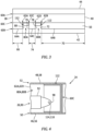
- the aircraft control surface 24 is provided with one or more internal actuator receptacles 80A and 80B (generally referred to as "80"). These actuator receptacles 80 are arranged spanwise along the base end spar 60B and the intermediate spar 60C. Each of the actuator receptacles 80 of FIG. 3 projects (e.g., partially) longitudinally into the aircraft control surface 24 from the control surface base 42 (and/or the base end spar 60B) to the intermediate spar 60C.
- the actuator receptacle 80A extends spanwise within the aircraft control surface 24 between and to the spanwise opposing internal stiffeners 62A and 62C.
- the actuator receptacle 80B extends spanwise within the aircraft control surface 24 between and to the spanwise opposing internal stiffeners 62B and 62D. Referring to FIG. 4 , each of the actuator receptacles 80 extends laterally between and to the control surface bottom skin 50 and the control surface top skin 52.
- the aircraft control surface 24 is moveably coupled with the aircraft base structure 22.
- the aircraft control surface 24 of FIG. 2 includes one or more control surface mounts 82 (e.g., hinge mounts) arranged spanwise along the base end spar 60B. Each of these control surface mounts 82 is longitudinally abutted against the base end spar 60B and a respective one of its segments 64. Each of the control surface mounts 82 is connected to the aircraft control surface 24.
- Each control surface mount 82 may be mechanically fastened and/or bonded to one or more of the control surface elements 50, 52, 60B and/or 64.
- Each control surface mount 82 of FIGS. 5A and 5B is pivotally connected to a respective base structure mount 84 (e.g., a hinge mount) of the aircraft base structure 22 through a pivot connection 86; e.g., a pin connection.
- the aircraft control surface 24 may thereby pivot about a control surface pivot axis 88 between a first position of FIG. 5A and a second position of FIG. 5B , or any intermediate position therebetween.
- the control surface pivot axis 88 may be arranged at the control surface base 42 and the control surface top skin 52.
- each actuation apparatus 26 may be configured as or otherwise include a linear actuator 90; e.g., a hydraulic actuator.
- the actuation apparatus of FIG. 1 for example, includes a housing 92 (e.g., a cylinder), a piston 94 and a driver 96 (e.g., a fixed length shaft such as a tie rod).
- the housing 92 is disposed at a control surface end 98 of the respective linear actuator 90.
- the piston 94 is arranged within an internal cavity 100 of the housing 92.
- This piston 94 is movable (e.g., translatable) within the housing 92 and its internal cavity 100 along an axial centerline 102 of the respective linear actuator 90.
- the driver 96 is connected to the piston 94.
- the driver 96 projects axially out from the piston 94 along the axial centerline 102 to a distal end 104 of the driver 96 at a base structure end 106 of the respective linear actuator 90.
- the actuation apparatus 26 and its linear actuator 90 of FIG. 1 are movably coupled with the aircraft base structure 22 and the aircraft control surface 24.
- the driver 96 of FIG. 1 for example, is pivotally attached to a (e.g., stationary) mount 108 (e.g., a clevis) of the base structure support structure 32 at the base structure end 106 through a pivot connection 110; e.g., a pin connection.
- the housing 92 of FIG. 1 is pivotally attached to a respective actuator mount 112 (e.g., a clevis) at the control surface end 98 through a pivot connection 114; e.g., a pin connection.
- the linear actuator 90 and its housing 92 may thereby pivot about an actuator pivot axis 116 between a first position (e.g., see position of FIG. 5A ) and a second position (e.g., see position of FIG. 5B ), or any intermediate position therebetween.
- the actuator pivot axis 116 of FIG. 1 is longitudinally and laterally offset from the control surface pivot axis 88 (see also FIGS. 5A and 5B ).
- the actuator pivot axis 116 of FIG. 1 in particular, is longitudinally recessed into the aircraft control surface 24 from the control surface pivot axis 88.
- Each respective actuator mount 112 of FIG. 2 for example, is longitudinally recessed into the aircraft control surface 24 from the control surface mounts 82. More particularly, each actuator mount 112 of FIG. 3 is mated with (e.g., disposed within) a respective one of the actuator receptacles 80 between a respective set of the spanwise opposing stiffeners 62A and 62C, 62B and 62D. Referring to FIG. 4 , each actuator mount 112 is connected to the aircraft control surface 24. Each actuator mount 112, for example, may be mechanically attached and/or bonded to one or more of the control surface elements 50, 52 and/or 60C.
- each actuation apparatus 26 and its linear actuator 90 is (e.g., partially or completely) disposed within a respective one of the actuator receptacles 80.
- This may reduce complexity and/or weight of the aircraft assembly 20 as compared to another system where an actuator is outside of an aircraft control surface.
- Arranging, locating, embedding the actuation apparatuses 26 and their linear actuators 90 into the aircraft control surface 24 may facilitate providing the aircraft base structure 22 and/or the aircraft control surface 24 with smaller dimensions and, thus, a more compact and/or lightweight form.
- openings in the base end spar 60B of FIG. 3 are boxed in by the elements 60C and 62A-D forming each actuator receptacle 80.
- the actuator receptacle elements 60C and 62A-D may thereby maintain or increase structural integrity of the aircraft control surface 24 about the actuator mounts 112.
- one or more or all of the actuation apparatuses 26 may each further include one or more linkages for motively coupling the linear actuator 90 and its driver 96 to another component; e.g., the aircraft base structure 22.
- the actuation apparatus 26 of FIG. 6 includes a link arm 118 (e.g., a tie rod) and a crank arm 120.
- the link arm 118 is between and is pivotally coupled to the driver 96 and the crank arm 120.
- the crank arm 120 may be fixedly attached to, for example, the aircraft base structure 22 through a shaft. With such an arrangement, at least the link arm 118 is movable relative to the aircraft base structure 22 and the aircraft control surface 24 during actuation apparatus operation.
- the aircraft control surface 24 may be constructed from a composite material; e.g., a fiber-reinforced composite material.
- the aircraft control surface 24 of FIG. 2 and its elements 50, 52 and 54 may be constructure from fiber-reinforcement (e.g., carbon fibers, fiberglass fibers and/or aramid fibers) with a polymer matrix (e.g., thermoset and/or thermoplastic).
- the aircraft control surface 24 may be constructed as a monolithic body. In other embodiments, one or more portions of the aircraft control surface 24 may be separately formed and subsequently attached (e.g., bonded) together.
- the aircraft assembly 20 is described above using the terms bottom and top with reference to the orientation in the drawings for ease of description.
- the aircraft assembly 20 of the present disclosure is not limited to any particular spatial orientations relative to gravity.
- the skin 50 may be gravitationally above the skin 52.
- the skins 50 and 52 may be gravitationally next to each other; e.g., the aircraft assembly 20 of FIG. 1 may be rotated ninety degrees.
Landscapes
- Engineering & Computer Science (AREA)
- Aviation & Aerospace Engineering (AREA)
- Physics & Mathematics (AREA)
- Fluid Mechanics (AREA)
- Automation & Control Theory (AREA)
- Transmission Devices (AREA)
Abstract
Description
- The present invention relates generally to an aircraft and, more particularly, to an aircraft control surface.
- An aircraft includes multiple control surfaces (sometimes referred to as flight control surfaces) for controlling aircraft flight. Various types and configurations of aircraft control surfaces and actuators for moving these aircraft control surfaces are known in the art. While these known aircraft control surfaces and actuators have various benefits, there is still room in the art for improvement. There is a need in the art, for example, for more compact aircraft control surfaces and/or airfoils to which the aircraft control surfaces are connected.
- According to an aspect of the present invention, an assembly is provided for an aircraft. This aircraft assembly includes an aircraft control surface. The aircraft control surface includes a first skin, a second skin and a support structure laterally between and connected to the first skin and the second skin. The support structure includes a spar, a first stiffener and a second stiffener. The spar extends spanwise within the aircraft control surface. The first stiffener extends longitudinally within the aircraft control surface to the spar. The second stiffener extends longitudinally within the aircraft control surface to the spar. An actuator receptacle projects longitudinally into the aircraft control surface from a base of the aircraft control surface to the spar. The actuator receptacle extends spanwise within the aircraft control surface between the first stiffener and the second stiffener.
- According to another aspect of the present invention, another assembly is provided for an aircraft. This aircraft assembly includes an aircraft control surface, a first actuation apparatus and a second actuation apparatus. The aircraft control surface extends spanwise between a first end and a second end. The aircraft control surface extends longitudinally between a base and a tip. The aircraft control surface extends laterally between a first side and a second side that meets the first side at the tip. The aircraft control surface includes a first actuator receptacle and a second actuator receptacle. Each of the first actuator receptacle and the second actuator receptacle projects partially longitudinally into the aircraft control surface from the base. Each of the first actuator receptacle and the second actuator receptacle extends spanwise within the aircraft control surface. Each of the first actuator receptacle and the second actuator receptacle extends laterally within the aircraft control surface. The first actuation apparatus is mated with the first actuator receptacle and pivotally connected to the aircraft control surface. The second actuation apparatus is mated with the second actuator receptacle and pivotally connected to the aircraft control surface.
- According to still another aspect of the present invention, another assembly is provided for an aircraft. This aircraft assembly includes an aircraft base structure, an aircraft control surface and an actuation apparatus. The aircraft control surface is pivotally attached to the aircraft base structure at a control surface pivot axis. The actuation apparatus includes a linear actuator and a linkage. A first end of the linear actuator is pivotally attached to the aircraft control surface at an actuator pivot axis, where the actuator pivot axis is recessed into the aircraft control surface from the control surface pivot axis. A second end of the linear actuator is pivotally attached to the linkage at a linkage pivot axis. The linkage may move relative to the aircraft base structure and the aircraft control surface during operation of the actuation apparatus.
- The following optional features may be applied to any of the above aspects.
- Optionally, and in accordance with any of the above, the aircraft control surface includes a first skin, a second skin, a spar, a first stiffener and a second stiffener. Optionally, and in accordance with any of the above, the spar extends spanwise within the aircraft control surface. Optionally, and in accordance with any of the above, the first stiffener extends longitudinally within the aircraft control surface to the spar. Optionally, and in accordance with any of the above, the second stiffener extends longitudinally within the aircraft control surface to the spar. Optionally, and in accordance with any of the above, the first actuator receptacle is formed by the spar, the first stiffener and the second stiffener laterally between the first skin and the second skin.
- Optionally, and in accordance with any of the above, the actuator receptacle extends laterally within the aircraft control surface between the first skin and the second skin.
- Optionally, and in accordance with any of the above, the aircraft assembly also includes an actuator mount disposed within the actuator receptacle and connected to the aircraft control surface.
- Optionally, and in accordance with any of the above, the actuator mount is connected to the spar.
- Optionally, and in accordance with any of the above, the actuator mount is connected to the first skin and/or the second skin.
- Optionally, and in accordance with any of the above, the aircraft assembly also includes a linear actuator disposed in the actuator receptacle and pivotally attached to the actuator mount.
- Optionally, and in accordance with any of the above, the aircraft assembly also includes a control surface mount connected to the support structure. Optionally, and in accordance with any of the above, a pivot axis of the actuator mount is longitudinally offset from a pivot axis of the control surface mount.
- Optionally, and in accordance with any of the above, the pivot axis of the actuator mount is also laterally offset from the pivot axis of the control surface mount.
- Optionally, and in accordance with any of the above, the aircraft assembly also includes a linear actuator disposed in the actuator receptacle and pivotally attached to the aircraft control surface.
- Optionally, and in accordance with any of the above, the linear actuator is configured as or otherwise includes a hydraulic actuator.
- Optionally, and in accordance with any of the above, the aircraft assembly may also include an aircraft base structure. Optionally, and in accordance with any of the above, the aircraft control surface is pivotally attached to the aircraft base structure at a first pivot axis. Optionally, and in accordance with any of the above, the linear actuator is pivotally attached to the aircraft control surface at a second pivot axis that is recessed into the aircraft control surface from the first pivot axis.
- Optionally, and in accordance with any of the above, the aircraft assembly also includes an aircraft base structure. Optionally, and in accordance with any of the above, the aircraft control surface is pivotally attached to the aircraft base structure at a first pivot axis. Optionally, and in accordance with any of the above, the linear actuator is pivotally attached to the aircraft control surface at a second pivot axis that is longitudinally and laterally offset from the first pivot axis.
- Optionally, and in accordance with any of the above, the support structure also includes a third stiffener and a fourth stiffener. Optionally, and in accordance with any of the above, the third stiffener extends longitudinally within the aircraft control surface to the spar. Optionally, and in accordance with any of the above, the fourth stiffener extends longitudinally within the aircraft control surface to the spar. Optionally, and in accordance with any of the above, a second actuator receptacle projects longitudinally into the aircraft control surface from the base to the spar. Optionally, and in accordance with any of the above, the second actuator receptacle extends spanwise within the aircraft control surface between the third stiffener and the fourth stiffener.
- Optionally, and in accordance with any of the above, the support structure also includes a segmented spar longitudinally spaced from the spar. Optionally, and in accordance with any of the above, the segmented spar includes a first spar segment and a second spar segment spanwise spaced from the first spar segment. Optionally, and in accordance with any of the above, the first stiffener extends longitudinally between the first spar segment and the spar. Optionally, and in accordance with any of the above, the second stiffener extends longitudinally between the second spar segment and the spar.
- Optionally, and in accordance with any of the above, the support structure also includes a second spar longitudinally between the spar and a tip of the aircraft control surface.
- Optionally, and in accordance with any of the above, the aircraft control surface is configured as or otherwise includes an aileron. Alternatively, the aircraft control surface may be configured as or otherwise include an elevator, a flap, a rudder or any other flight control surface.
- Optionally, and in accordance with any of the above, the aircraft control surface is constructed from or otherwise includes fiber-reinforced composite material.
- The present disclosure may include any one or more of the individual features disclosed above and/or below alone or in any combination thereof.
- The foregoing features and the operation of the invention will become more apparent in light of the following description and the accompanying drawings.
-
-
FIG. 1 is a side sectional illustration of a portion of an aircraft assembly. -
FIG. 2 is a perspective illustration of an aircraft control surface for the aircraft assembly configured with multiple actuation apparatuses partially shown. -
FIG. 3 is a plan view sectional illustration of the aircraft control surface with multiple actuator mounts schematically shown. -
FIG. 4 is a side sectional illustration of a pivot connection between a respective one of the actuation apparatuses and the aircraft control surface. -
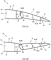
FIG. 5A is a sectional illustration of a portion of the aircraft assembly with its aircraft control surface in a first position. -
FIG. 5B is a sectional illustration of a portion of the aircraft assembly with its aircraft control surface in a second position. -
FIG. 6 is a diagrammatic illustration of a portion of the aircraft assembly with multiple linkages coupled to a linear actuator. -
FIG. 1 illustrates anassembly 20 for an aircraft such as, but not limited to, an airplane. Theaircraft assembly 20 includes a stationaryaircraft base structure 22 and a moveableaircraft control surface 24, which may also be referred to as a flight control surface. Theaircraft assembly 20 also includes one or more actuation apparatuses 26 (one depicted inFIG. 1 ; see alsoFIG. 2 ) configured to move (e.g., pivot) theaircraft control surface 24 relative to theaircraft base structure 22. - The
aircraft base structure 22 may be configured as an airfoil for the aircraft. Theaircraft base structure 22 ofFIG. 1 , for example, is configured as an aircraft wing. The present disclosure, however, is not limited to such an exemplary aircraft base structure. Theaircraft base structure 22, for example, may alternatively be configured as a horizontal stabilizer, a vertical stabilizer or any other member of the aircraft supporting an aircraft control surface. - The
aircraft base structure 22 ofFIG. 1 includes anexterior bottom skin 28, an exteriortop skin 30 and aninternal support structure 32. The basestructure bottom skin 28 forms an exterior bottomaerodynamic flow surface 34 of theaircraft base structure 22. The basestructure top skin 30 forms an exterior topaerodynamic flow surface 36 of theaircraft base structure 22. The basestructure support structure 32 is arranged between the basestructure bottom skin 28 and the basestructure top skin 30. This basestructure support structure 32 provides an internal rigid frame supporting the basestructure bottom skin 28 and the basestructure top skin 30. The basestructure support structure 32 ofFIG. 1 extends laterally between and is connected to the basestructure bottom skin 28 and the basestructure top skin 30. This basestructure support structure 32 may include one or more internal spars, one or more internal stiffeners and/or one or more other structural members. - The
aircraft control surface 24 is an aerodynamic body configured to adjust, maintain and/or otherwise control one or more flight parameters; e.g., altitude, pitch, roll, etc. Theaircraft control surface 24 ofFIG. 1 , for example, is configured as an aileron. The present disclosure, however, is not limited to such an exemplary aircraft control surface. Theaircraft control surface 24, for example, may alternatively be configured as an elevator, a flap, a rudder or any other flight control surface. - Referring to
FIG. 2 , theaircraft control surface 24 extends spanwise along a span line between afirst end 38 of theaircraft control surface 24 and asecond end 40 of theaircraft control surface 24. Theaircraft control surface 24 extends longitudinally along a camber line between a base 42 of theaircraft control surface 24 and a tip 44 (e.g., a trailing edge) of theaircraft control surface 24. Theaircraft control surface 24 extends laterally between a bottom side 46 of theaircraft control surface 24 and a top side 48 of theaircraft control surface 24. - The
aircraft control surface 24 ofFIG. 2 includes abottom skin 50, atop skin 52 and aninternal support structure 54. The controlsurface bottom skin 50 forms an exterior bottom aerodynamic surface 56 of theaircraft control surface 24 at the control surface bottom side 46. This controlsurface bottom skin 50 extends spanwise between and to the control surfacefirst end 38 and the control surfacesecond end 40. The controlsurface bottom skin 50 extends longitudinally between and to thecontrol surface base 42 and thecontrol surface tip 44, where the controlsurface bottom skin 50 may meet the controlsurface top skin 52 at thecontrol surface tip 44. - The control
surface top skin 52 forms an exterior top aerodynamic surface 58 of theaircraft control surface 24 at the control surface top side 48. This controlsurface top skin 52 extends spanwise between and to the control surfacefirst end 38 and the control surfacesecond end 40. The controlsurface top skin 52 extends longitudinally between and to thecontrol surface base 42 and thecontrol surface tip 44. - The control
surface support structure 54 is arranged between the controlsurface bottom skin 50 and the controlsurface top skin 52. This controlsurface support structure 54 provides an internal rigid frame supporting the controlsurface bottom skin 50 and the controlsurface top skin 52. The controlsurface support structure 54 ofFIG. 2 , for example, includes one or moreinternal spars 60A-C (generally referred to as "60") and one or moreinternal stiffeners 62A-D (generally referred to as "62"). - Each of the support structure elements 60 and 62 may extend laterally between and may engage (e.g., contact) the control
surface bottom skin 50 and the controlsurface top skin 52. Each of the support structure elements 60 and 62 may also be connected to (e.g., formed integral with, or mechanically fastened, bonded and/or otherwise fixedly attached to) the controlsurface bottom skin 50 and/or the controlsurface top skin 52. Each of the internal spars 60 ofFIG. 2 extends spanwise within theaircraft control surface 24 along the control surface skins 50 and 52, for example between and to (or about) the control surfacefirst end 38 and the control surfacesecond end 40. Each of the internal stiffeners 62 ofFIG. 2 extends longitudinally within theaircraft control surface 24 along the control surface skins 50 and 52, for example from (or about) thecontrol surface base 42 towards thecontrol surface tip 44. - Referring to
FIG. 3 , the tip end spar 60A may be arranged at (e.g., on, adjacent or proximate) and extend spanwise along thecontrol surface tip 44. Thebase end spar 60B may be arranged at and extend spanwise along thecontrol surface base 42. Theintermediate spar 60C is arranged longitudinally between and longitudinally spaced from the tip end spar 60A and the base end spar 60B. The tip end spar 60A and theintermediate spar 60C may each be configured as a continuous spar. Each of theinternal spars FIG. 3 , for example, extends uninterrupted between and to (or about) the control surfacefirst end 38 and the control surfacesecond end 40. Thebase end spar 60B, by contrast, may be configured as a segmented spar. Thebase end spar 60B ofFIG. 3 , for example, includes a plurality ofdiscrete spar segments 64A-C (generally referred to as "64"). - The first
end spar segment 64A is arranged at the control surfacefirst end 38. The firstend spar segment 64A ofFIG. 3 , for example, extends spanwise a first endspar segment distance 66 from the control surfacefirst end 38 to asecond end 68 of the firstend spar segment 64A. - The second
end spar segment 64B is arranged at the control surfacesecond end 40. The secondend spar segment 64B ofFIG. 3 , for example, extends spanwise a second endspar segment distance 70 from the control surfacesecond end 40 to afirst end 72 of the secondend spar segment 64B. This second endspar segment distance 70 may be different (e.g., greater) than the first endspar segment distance 66. The second endspar segment distance 70, for example, may be between two times (2x) and ten times (10x) greater than the first endspar segment distance 66. The present disclosure, however, is not limited to such an exemplary dimensional relationship. For example, in other embodiments, the second endspar segment distance 70 may be less than two times greater than the first endspar segment distance 66, or more than ten times greater than the first endspar segment distance 66. - The
intermediate spar segment 64C is arranged spanwise between the firstend spar segment 64A and the secondend spar segment 64B. Theintermediate spar segment 64C ofFIG. 3 , for example, extends spanwise an intermediatespar segment distance 74 from afirst end 76 of theintermediate spar segment 64C to asecond end 78 of theintermediate spar segment 64C. This intermediatespar segment distance 74 may be different (e.g., less) than the first endspar segment distance 66 and/or the second endspar segment distance 70. The intermediatespar segment distance 74, for example, may be between one-fifth (1/5) and four-fifths (4/5) of the first endspar segment distance 66. The present disclosure, however, is not limited to such an exemplary dimensional relationship. For example, in other embodiments, the intermediatespar segment distance 74 may be greater than four-fifths of the first endspar segment distance 66. The intermediate spar segmentfirst end 76 is spanwise spaced from the first end spar segmentsecond end 68. The intermediate spar segmentsecond end 78 is spanwise spaced from the second end spar segmentfirst end 72. - Each of the internal stiffeners 62 of
FIG. 3 extends longitudinally (e.g., only or at least) between and to the base end spar 60B and theintermediate spar 60C. Theinternal stiffener 62A, for example, extends spanwise to and is connected to the firstend spar segment 64A at itssecond end 68. Theinternal stiffener 62B extends spanwise to and is connected to the secondend spar segment 64B at itsfirst end 72. Theinternal stiffener 62C extends spanwise to and is connected to theintermediate spar segment 64C at itsfirst end 76. Theinternal stiffener 62D extends spanwise to and is connected to theintermediate spar segment 64C at itssecond end 78. - With the foregoing arrangement, the
aircraft control surface 24 is provided with one or moreinternal actuator receptacles intermediate spar 60C. Each of the actuator receptacles 80 ofFIG. 3 projects (e.g., partially) longitudinally into theaircraft control surface 24 from the control surface base 42 (and/or the base end spar 60B) to theintermediate spar 60C. Theactuator receptacle 80A extends spanwise within theaircraft control surface 24 between and to the spanwise opposinginternal stiffeners actuator receptacle 80B extends spanwise within theaircraft control surface 24 between and to the spanwise opposinginternal stiffeners FIG. 4 , each of the actuator receptacles 80 extends laterally between and to the controlsurface bottom skin 50 and the controlsurface top skin 52. - Referring to
FIGS. 5A and 5B , theaircraft control surface 24 is moveably coupled with theaircraft base structure 22. Theaircraft control surface 24 ofFIG. 2 , for example, includes one or more control surface mounts 82 (e.g., hinge mounts) arranged spanwise along the base end spar 60B. Each of these control surface mounts 82 is longitudinally abutted against the base end spar 60B and a respective one of its segments 64. Each of the control surface mounts 82 is connected to theaircraft control surface 24. Eachcontrol surface mount 82, for example, may be mechanically fastened and/or bonded to one or more of thecontrol surface elements - Each control surface mount 82 of
FIGS. 5A and 5B is pivotally connected to a respective base structure mount 84 (e.g., a hinge mount) of theaircraft base structure 22 through a pivot connection 86; e.g., a pin connection. Theaircraft control surface 24 may thereby pivot about a controlsurface pivot axis 88 between a first position ofFIG. 5A and a second position ofFIG. 5B , or any intermediate position therebetween. The controlsurface pivot axis 88 may be arranged at thecontrol surface base 42 and the controlsurface top skin 52. - Referring to
FIG. 1 , eachactuation apparatus 26 may be configured as or otherwise include alinear actuator 90; e.g., a hydraulic actuator. The actuation apparatus ofFIG. 1 , for example, includes a housing 92 (e.g., a cylinder), apiston 94 and a driver 96 (e.g., a fixed length shaft such as a tie rod). Thehousing 92 is disposed at acontrol surface end 98 of the respectivelinear actuator 90. Thepiston 94 is arranged within aninternal cavity 100 of thehousing 92. Thispiston 94 is movable (e.g., translatable) within thehousing 92 and itsinternal cavity 100 along anaxial centerline 102 of the respectivelinear actuator 90. Thedriver 96 is connected to thepiston 94. Thedriver 96 projects axially out from thepiston 94 along theaxial centerline 102 to a distal end 104 of thedriver 96 at a base structure end 106 of the respectivelinear actuator 90. - The
actuation apparatus 26 and itslinear actuator 90 ofFIG. 1 are movably coupled with theaircraft base structure 22 and theaircraft control surface 24. Thedriver 96 ofFIG. 1 , for example, is pivotally attached to a (e.g., stationary) mount 108 (e.g., a clevis) of the basestructure support structure 32 at the base structure end 106 through apivot connection 110; e.g., a pin connection. Thehousing 92 ofFIG. 1 is pivotally attached to a respective actuator mount 112 (e.g., a clevis) at thecontrol surface end 98 through a pivot connection 114; e.g., a pin connection. Thelinear actuator 90 and itshousing 92 may thereby pivot about an actuator pivot axis 116 between a first position (e.g., see position ofFIG. 5A ) and a second position (e.g., see position ofFIG. 5B ), or any intermediate position therebetween. - The actuator pivot axis 116 of
FIG. 1 is longitudinally and laterally offset from the control surface pivot axis 88 (see alsoFIGS. 5A and 5B ). The actuator pivot axis 116 ofFIG. 1 , in particular, is longitudinally recessed into theaircraft control surface 24 from the controlsurface pivot axis 88. Eachrespective actuator mount 112 ofFIG. 2 , for example, is longitudinally recessed into theaircraft control surface 24 from the control surface mounts 82. More particularly, eachactuator mount 112 ofFIG. 3 is mated with (e.g., disposed within) a respective one of the actuator receptacles 80 between a respective set of the spanwiseopposing stiffeners FIG. 4 , eachactuator mount 112 is connected to theaircraft control surface 24. Eachactuator mount 112, for example, may be mechanically attached and/or bonded to one or more of thecontrol surface elements - With the foregoing arrangement, each
actuation apparatus 26 and itslinear actuator 90 is (e.g., partially or completely) disposed within a respective one of the actuator receptacles 80. This may reduce complexity and/or weight of theaircraft assembly 20 as compared to another system where an actuator is outside of an aircraft control surface. Arranging, locating, embedding theactuation apparatuses 26 and theirlinear actuators 90 into theaircraft control surface 24 may facilitate providing theaircraft base structure 22 and/or theaircraft control surface 24 with smaller dimensions and, thus, a more compact and/or lightweight form. Furthermore, openings in thebase end spar 60B ofFIG. 3 are boxed in by theelements actuator receptacle elements aircraft control surface 24 about the actuator mounts 112. - In some embodiments, referring to
FIG. 6 , one or more or all of theactuation apparatuses 26 may each further include one or more linkages for motively coupling thelinear actuator 90 and itsdriver 96 to another component; e.g., theaircraft base structure 22. Theactuation apparatus 26 ofFIG. 6 , for example, includes a link arm 118 (e.g., a tie rod) and acrank arm 120. Thelink arm 118 is between and is pivotally coupled to thedriver 96 and thecrank arm 120. Thecrank arm 120 may be fixedly attached to, for example, theaircraft base structure 22 through a shaft. With such an arrangement, at least thelink arm 118 is movable relative to theaircraft base structure 22 and theaircraft control surface 24 during actuation apparatus operation. - In some embodiments, the
aircraft control surface 24 may be constructed from a composite material; e.g., a fiber-reinforced composite material. Theaircraft control surface 24 ofFIG. 2 and itselements aircraft control surface 24 may be constructed as a monolithic body. In other embodiments, one or more portions of theaircraft control surface 24 may be separately formed and subsequently attached (e.g., bonded) together. - The
aircraft assembly 20 is described above using the terms bottom and top with reference to the orientation in the drawings for ease of description. Theaircraft assembly 20 of the present disclosure, however, is not limited to any particular spatial orientations relative to gravity. For example, in other embodiments, theskin 50 may be gravitationally above theskin 52. In still other embodiments, theskins aircraft assembly 20 ofFIG. 1 may be rotated ninety degrees. - While various embodiments of the present invention have been disclosed, it will be apparent to those of ordinary skill in the art that many more embodiments and implementations are possible within the scope of the invention. For example, the present invention as described herein includes several aspects and embodiments that include particular features. Although these features may be described individually, it is within the scope of the present invention that some or all of these features may be combined with any one of the aspects and remain within the scope of the invention. Accordingly, the present invention is not to be restricted except in light of the attached claims and their equivalents.
Claims (15)
- An assembly (20) for an aircraft, comprising:an aircraft control surface (24) including a first skin (50), a second skin (52) and a support structure laterally between and connected to the first skin (50) and the second skin (52), the support structure including a spar (60C), a first stiffener (62A) and a second stiffener (62C), the spar (60C) extending spanwise within the aircraft control surface (24), the first stiffener extending longitudinally within the aircraft control surface (24) to the spar (60C), and the second stiffener(62C) extending longitudinally within the aircraft control surface (24) to the spar; andan actuator receptacle (80A) projecting longitudinally into the aircraft control surface (24) from a base (42) of the aircraft control surface (24) to the spar (60C), the actuator receptacle (80A) extending spanwise within the aircraft control surface (24) between the first stiffener (60A) and the second stiffener (60C).
- The assembly (20) of claim 1, wherein the actuator receptacle (80A) extends laterally within the aircraft control surface (24) between the first skin (50) and the second skin (52).
- The assembly (20) of claims 1 or 2, further comprising an actuator mount (112) disposed within the actuator receptacle (80A) and connected to the aircraft control surface (24).
- The assembly (20) of claim 3, wherein the actuator mount (112) is connected to:the spar; and/orat least one of the first skin (50) or the second skin (52).
- The assembly (20) of claims 3 or 4, further comprising a linear actuator (90) disposed in the actuator receptacle (80A) and pivotally attached to the actuator mount (112) optionally wherein the linear actuator (90) comprises a hydraulic actuator.
- The assembly (20) of any of claims 3 to 5, further comprising a control surface mount (82) connected to the support structure and a pivot axis (116) of the actuator mount (112) longitudinally offset from a pivot axis of the control surface mount (82), optionally wherein the pivot axis (116) of the actuator mount (112) is laterally offset from the pivot axis (88) of the control surface mount (82).
- The assembly (20) of any of claims 1 to 4, further comprising a linear actuator (90) disposed in the actuator receptacle (80A) and pivotally attached to the aircraft control surface (24) optionally wherein the linear actuator (90) comprises a hydraulic actuator.
- The assembly (20) of claim 7, further comprising an aircraft base structure (22), wherein:the aircraft control surface (24) is pivotally attached to the aircraft base structure (22) at a first pivot axis; andthe linear actuator (90) pivotally attached to the aircraft control surface (24) at a second pivot axis (116) that is:recessed into the aircraft control surface (24) from the first pivot axis; and/orlongitudinally and laterally offset from the first pivot axis.
- The assembly (20) of any preceding claim, wherein:the support structure further includes a third stiffener (62D) and a fourth stiffener (62B);the third stiffener (62D) extends longitudinally within the aircraft control surface (24) to the spar;the fourth stiffener (62B) extends longitudinally within the aircraft control surface (24) to the spar (60C); anda second actuator receptacle (80A) projects longitudinally into the aircraft control surface (24) from the base (42) to the spar (60C), and the second actuator receptacle (80A) extends spanwise within the aircraft control surface (24) between the third stiffener (62D) and the fourth stiffener (62B).
- The assembly (20) of any preceding claim, wherein:the support structure further includes a segmented spar (60B) longitudinally spaced from the spar (60C), and the segmented spar (60B) includes a first spar segment (64A) and a second spar segment (64C) spanwise spaced from the first spar segment (64A);the first stiffener (62A) extends longitudinally between the first spar segment (64A) and the spar (60C); andthe second stiffener (62C) extends longitudinally between the second spar (64C) segment and the spar (60C).
- The assembly (20) of any preceding claim, wherein the support structure further includes a second spar (60A) longitudinally between the spar (60C) and a tip (44) of the aircraft control surface (24).
- The assembly (20) of any preceding claim, wherein the aircraft control surface (24) comprises:an aileron; and/orfiber-reinforced composite material
- An assembly (20) for an aircraft, comprising:an aircraft control surface (24) extending spanwise between a first end (38) and a second end (40), the aircraft control surface (24) extending longitudinally between a base (42) and a tip (44), the aircraft control surface (24) extending laterally between a first side (50) and a second side (52) that meets the first side (50) at the tip (44), and the aircraft control surface (24) comprising a first actuator receptacle (80A) and a second actuator receptacle (80B), each of the first actuator receptacle (80A) and the second actuator receptacle (80B) projecting partially longitudinally into the aircraft control surface (24) from the base (42), each of the first actuator receptacle (80A) and the second actuator receptacle (80A) extending spanwise within the aircraft control surface (24), and each of the first actuator receptacle (80A) and the second actuator receptacle (80A) extending laterally within the aircraft control surface (24);a first actuation apparatus (26) mated with the first actuator receptacle (80A) and pivotally connected to the aircraft control surface (24); anda second actuation apparatus (26) mated with the second actuator receptacle (80B) and pivotally connected to the aircraft control surface (24).
- The assembly (20) of claim 13, wherein:the aircraft control surface (24) further includes a first skin (50), a second skin (52), a spar, a first stiffener and a second stiffener;the spar extends spanwise within the aircraft control surface (24);the first stiffener (62A) extends longitudinally within the aircraft control surface (24) to the spar (60C);the second stiffener (62C) extends longitudinally within the aircraft control surface (24) to the spar (60C); andthe first actuator receptacle (80A) is formed by the spar (60C), the first stiffener (62A) and the second stiffener (62C) laterally between the first skin (50) and the second skin (52).
- An assembly (20) for an aircraft, comprising:an aircraft base structure (22);an aircraft control surface (24) pivotally attached to the aircraft base structure (22) at a control surface pivot axis (88); andan actuation apparatus (26) comprising a linear actuator (90) and a linkage, a first end of the linear actuator (90) pivotally attached to the aircraft control surface (24) at an actuator pivot axis (116) recessed into the aircraft control surface (24) from the control surface pivot axis (88), and a second end of the linear actuator (90) pivotally attached to the linkage at a linkage pivot axis, wherein the linkage moves relative to the aircraft base structure (22) and the aircraft control surface (24) during operation of the actuation apparatus (26).
Applications Claiming Priority (1)
| Application Number | Priority Date | Filing Date | Title |
|---|---|---|---|
| US17/671,097 US11827338B2 (en) | 2022-02-14 | 2022-02-14 | Aircraft control surface with linear actuator |
Publications (2)
| Publication Number | Publication Date |
|---|---|
| EP4227213A1 true EP4227213A1 (en) | 2023-08-16 |
| EP4227213B1 EP4227213B1 (en) | 2026-04-01 |
Family
ID=85238966
Family Applications (1)
| Application Number | Title | Priority Date | Filing Date |
|---|---|---|---|
| EP23156649.8A Active EP4227213B1 (en) | 2022-02-14 | 2023-02-14 | Aircraft control surface with linear actuator |
Country Status (2)
| Country | Link |
|---|---|
| US (1) | US11827338B2 (en) |
| EP (1) | EP4227213B1 (en) |
Cited By (1)
| Publication number | Priority date | Publication date | Assignee | Title |
|---|---|---|---|---|
| EP4238868A1 (en) * | 2022-03-01 | 2023-09-06 | Goodrich Actuation Systems SAS | Flight control actuator |
Families Citing this family (3)
| Publication number | Priority date | Publication date | Assignee | Title |
|---|---|---|---|---|
| EP4180689A1 (en) * | 2021-11-12 | 2023-05-17 | Goodrich Actuation Systems SAS | Damping device |
| EP4400420B1 (en) * | 2023-01-13 | 2026-02-04 | Goodrich Actuation Systems SAS | Ema droop function and stops protection management |
| EP4660076A1 (en) * | 2024-06-04 | 2025-12-10 | Goodrich Actuation Systems SAS | Actuator assembly architecture |
Citations (3)
| Publication number | Priority date | Publication date | Assignee | Title |
|---|---|---|---|---|
| US2927469A (en) * | 1958-05-26 | 1960-03-08 | Avro Aircraft Ltd | Aircraft control surface actuating mechanism |
| EP3323712A1 (en) * | 2016-11-21 | 2018-05-23 | The Boeing Company | Aircraft flap hinge |
| US20200080588A1 (en) * | 2018-09-07 | 2020-03-12 | Nabtesco Corporation | Joining of fiber-containing composite material |
Family Cites Families (5)
| Publication number | Priority date | Publication date | Assignee | Title |
|---|---|---|---|---|
| US4595158A (en) | 1983-09-26 | 1986-06-17 | The Boeing Company | Aircraft control surface actuation and counterbalancing |
| US4773620A (en) * | 1987-03-23 | 1988-09-27 | The United States Of America As Represented By The Administrator Of The National Aeronautics And Space Administration | Control surface actuator |
| JP6626690B2 (en) * | 2015-11-05 | 2019-12-25 | ナブテスコ株式会社 | Support structure of force transmission member |
| US11518496B2 (en) | 2019-08-27 | 2022-12-06 | The Boeing Company | Flap actuation systems for aircraft |
| US11505304B2 (en) | 2019-10-18 | 2022-11-22 | The Boeing Company | Aircraft spoiler actuation systems and related methods |
-
2022
- 2022-02-14 US US17/671,097 patent/US11827338B2/en active Active
-
2023
- 2023-02-14 EP EP23156649.8A patent/EP4227213B1/en active Active
Patent Citations (3)
| Publication number | Priority date | Publication date | Assignee | Title |
|---|---|---|---|---|
| US2927469A (en) * | 1958-05-26 | 1960-03-08 | Avro Aircraft Ltd | Aircraft control surface actuating mechanism |
| EP3323712A1 (en) * | 2016-11-21 | 2018-05-23 | The Boeing Company | Aircraft flap hinge |
| US20200080588A1 (en) * | 2018-09-07 | 2020-03-12 | Nabtesco Corporation | Joining of fiber-containing composite material |
Cited By (1)
| Publication number | Priority date | Publication date | Assignee | Title |
|---|---|---|---|---|
| EP4238868A1 (en) * | 2022-03-01 | 2023-09-06 | Goodrich Actuation Systems SAS | Flight control actuator |
Also Published As
| Publication number | Publication date |
|---|---|
| EP4227213B1 (en) | 2026-04-01 |
| US11827338B2 (en) | 2023-11-28 |
| US20230257107A1 (en) | 2023-08-17 |
Similar Documents
| Publication | Publication Date | Title |
|---|---|---|
| EP4227213B1 (en) | Aircraft control surface with linear actuator | |
| US9889922B2 (en) | Flap support | |
| EP2593361B1 (en) | Aircraft flap actuator assembly | |
| US12246822B2 (en) | Aircraft control surface with integrated hydraulic actuator | |
| CA3035269C (en) | Wing flap with torque member and method for forming thereof | |
| US12409925B1 (en) | Morphing airfoil | |
| US10597141B2 (en) | Wing flap with torque member and method for forming thereof | |
| CN110316354B (en) | Flap with torque member and method of forming the same | |
| US20210061443A1 (en) | Flap actuation systems for aircraft | |
| CA2814493C (en) | Method and apparatus for actively manipulating aerodynamic surfaces | |
| US5110072A (en) | Control surface stabilizer hinge | |
| EP2886450A1 (en) | Aircraft control surface | |
| US12077291B2 (en) | System of morphing control surface for aircraft wing | |
| US11338905B2 (en) | Offset drive arm actuation of inboard flaps | |
| US20230082202A1 (en) | Composite airfoil for an aircraft | |
| GB2605151A (en) | An aircraft wing trailing edge section assembly |
Legal Events
| Date | Code | Title | Description |
|---|---|---|---|
| PUAI | Public reference made under article 153(3) epc to a published international application that has entered the european phase |
Free format text: ORIGINAL CODE: 0009012 |
|
| STAA | Information on the status of an ep patent application or granted ep patent |
Free format text: STATUS: THE APPLICATION HAS BEEN PUBLISHED |
|
| AK | Designated contracting states |
Kind code of ref document: A1 Designated state(s): AL AT BE BG CH CY CZ DE DK EE ES FI FR GB GR HR HU IE IS IT LI LT LU LV MC ME MK MT NL NO PL PT RO RS SE SI SK SM TR |
|
| STAA | Information on the status of an ep patent application or granted ep patent |
Free format text: STATUS: REQUEST FOR EXAMINATION WAS MADE |
|
| 17P | Request for examination filed |
Effective date: 20240216 |
|
| RBV | Designated contracting states (corrected) |
Designated state(s): AL AT BE BG CH CY CZ DE DK EE ES FI FR GB GR HR HU IE IS IT LI LT LU LV MC ME MK MT NL NO PL PT RO RS SE SI SK SM TR |
|
| STAA | Information on the status of an ep patent application or granted ep patent |
Free format text: STATUS: EXAMINATION IS IN PROGRESS |
|
| 17Q | First examination report despatched |
Effective date: 20250211 |
|
| GRAP | Despatch of communication of intention to grant a patent |
Free format text: ORIGINAL CODE: EPIDOSNIGR1 |
|
| STAA | Information on the status of an ep patent application or granted ep patent |
Free format text: STATUS: GRANT OF PATENT IS INTENDED |
|
| RIC1 | Information provided on ipc code assigned before grant |
Ipc: B64C 9/02 20060101AFI20250822BHEP Ipc: B64C 9/00 20060101ALN20250822BHEP |
|
| INTG | Intention to grant announced |
Effective date: 20250916 |
|
| GRAS | Grant fee paid |
Free format text: ORIGINAL CODE: EPIDOSNIGR3 |
|
| GRAA | (expected) grant |
Free format text: ORIGINAL CODE: 0009210 |
|
| STAA | Information on the status of an ep patent application or granted ep patent |
Free format text: STATUS: THE PATENT HAS BEEN GRANTED |
|
| AK | Designated contracting states |
Kind code of ref document: B1 Designated state(s): AL AT BE BG CH CY CZ DE DK EE ES FI FR GB GR HR HU IE IS IT LI LT LU LV MC ME MK MT NL NO PL PT RO RS SE SI SK SM TR |
|
| REG | Reference to a national code |
Ref country code: CH Ref legal event code: F10 Free format text: ST27 STATUS EVENT CODE: U-0-0-F10-F00 (AS PROVIDED BY THE NATIONAL OFFICE) Effective date: 20260401 Ref country code: GB Ref legal event code: FG4D |
|
| REG | Reference to a national code |
Ref country code: DE Ref legal event code: R096 Ref document number: 602023014273 Country of ref document: DE |
|
| REG | Reference to a national code |
Ref country code: IE Ref legal event code: FG4D |