EP4227208A1 - Gas treatment system and ship including same - Google Patents
Gas treatment system and ship including same Download PDFInfo
- Publication number
- EP4227208A1 EP4227208A1 EP21878060.9A EP21878060A EP4227208A1 EP 4227208 A1 EP4227208 A1 EP 4227208A1 EP 21878060 A EP21878060 A EP 21878060A EP 4227208 A1 EP4227208 A1 EP 4227208A1
- Authority
- EP
- European Patent Office
- Prior art keywords
- coolant
- heat exchanger
- main engine
- circulation line
- line
- Prior art date
- Legal status (The legal status is an assumption and is not a legal conclusion. Google has not performed a legal analysis and makes no representation as to the accuracy of the status listed.)
- Pending
Links
Images

Classifications
-
- B—PERFORMING OPERATIONS; TRANSPORTING
- B63—SHIPS OR OTHER WATERBORNE VESSELS; RELATED EQUIPMENT
- B63H—MARINE PROPULSION OR STEERING
- B63H21/00—Use of propulsion power plant or units on vessels
- B63H21/38—Apparatus or methods specially adapted for use on marine vessels, for handling power plant or unit liquids, e.g. lubricants, coolants, fuels or the like
-
- B—PERFORMING OPERATIONS; TRANSPORTING
- B63—SHIPS OR OTHER WATERBORNE VESSELS; RELATED EQUIPMENT
- B63B—SHIPS OR OTHER WATERBORNE VESSELS; EQUIPMENT FOR SHIPPING
- B63B17/00—Vessels parts, details, or accessories, not otherwise provided for
- B63B17/0027—Tanks for fuel or the like ; Accessories therefor, e.g. tank filler caps
-
- B—PERFORMING OPERATIONS; TRANSPORTING
- B63—SHIPS OR OTHER WATERBORNE VESSELS; RELATED EQUIPMENT
- B63B—SHIPS OR OTHER WATERBORNE VESSELS; EQUIPMENT FOR SHIPPING
- B63B25/00—Load-accommodating arrangements, e.g. stowing, trimming; Vessels characterised thereby
- B63B25/02—Load-accommodating arrangements, e.g. stowing, trimming; Vessels characterised thereby for bulk goods
- B63B25/08—Load-accommodating arrangements, e.g. stowing, trimming; Vessels characterised thereby for bulk goods fluid
- B63B25/12—Load-accommodating arrangements, e.g. stowing, trimming; Vessels characterised thereby for bulk goods fluid closed
- B63B25/16—Load-accommodating arrangements, e.g. stowing, trimming; Vessels characterised thereby for bulk goods fluid closed heat-insulated
-
- F—MECHANICAL ENGINEERING; LIGHTING; HEATING; WEAPONS; BLASTING
- F02—COMBUSTION ENGINES; HOT-GAS OR COMBUSTION-PRODUCT ENGINE PLANTS
- F02M—SUPPLYING COMBUSTION ENGINES IN GENERAL WITH COMBUSTIBLE MIXTURES OR CONSTITUENTS THEREOF
- F02M21/00—Apparatus for supplying engines with non-liquid fuels, e.g. gaseous fuels stored in liquid form
- F02M21/02—Apparatus for supplying engines with non-liquid fuels, e.g. gaseous fuels stored in liquid form for gaseous fuels
- F02M21/0203—Apparatus for supplying engines with non-liquid fuels, e.g. gaseous fuels stored in liquid form for gaseous fuels characterised by the type of gaseous fuel
- F02M21/0209—Hydrocarbon fuels, e.g. methane or acetylene
-
- F—MECHANICAL ENGINEERING; LIGHTING; HEATING; WEAPONS; BLASTING
- F02—COMBUSTION ENGINES; HOT-GAS OR COMBUSTION-PRODUCT ENGINE PLANTS
- F02M—SUPPLYING COMBUSTION ENGINES IN GENERAL WITH COMBUSTIBLE MIXTURES OR CONSTITUENTS THEREOF
- F02M21/00—Apparatus for supplying engines with non-liquid fuels, e.g. gaseous fuels stored in liquid form
- F02M21/02—Apparatus for supplying engines with non-liquid fuels, e.g. gaseous fuels stored in liquid form for gaseous fuels
- F02M21/0218—Details on the gaseous fuel supply system, e.g. tanks, valves, pipes, pumps, rails, injectors or mixers
-
- F—MECHANICAL ENGINEERING; LIGHTING; HEATING; WEAPONS; BLASTING
- F02—COMBUSTION ENGINES; HOT-GAS OR COMBUSTION-PRODUCT ENGINE PLANTS
- F02M—SUPPLYING COMBUSTION ENGINES IN GENERAL WITH COMBUSTIBLE MIXTURES OR CONSTITUENTS THEREOF
- F02M21/00—Apparatus for supplying engines with non-liquid fuels, e.g. gaseous fuels stored in liquid form
- F02M21/02—Apparatus for supplying engines with non-liquid fuels, e.g. gaseous fuels stored in liquid form for gaseous fuels
- F02M21/0218—Details on the gaseous fuel supply system, e.g. tanks, valves, pipes, pumps, rails, injectors or mixers
- F02M21/0227—Means to treat or clean gaseous fuels or fuel systems, e.g. removal of tar, cracking, reforming or enriching
-
- F—MECHANICAL ENGINEERING; LIGHTING; HEATING; WEAPONS; BLASTING
- F02—COMBUSTION ENGINES; HOT-GAS OR COMBUSTION-PRODUCT ENGINE PLANTS
- F02M—SUPPLYING COMBUSTION ENGINES IN GENERAL WITH COMBUSTIBLE MIXTURES OR CONSTITUENTS THEREOF
- F02M21/00—Apparatus for supplying engines with non-liquid fuels, e.g. gaseous fuels stored in liquid form
- F02M21/02—Apparatus for supplying engines with non-liquid fuels, e.g. gaseous fuels stored in liquid form for gaseous fuels
- F02M21/06—Apparatus for de-liquefying, e.g. by heating
-
- F—MECHANICAL ENGINEERING; LIGHTING; HEATING; WEAPONS; BLASTING
- F02—COMBUSTION ENGINES; HOT-GAS OR COMBUSTION-PRODUCT ENGINE PLANTS
- F02M—SUPPLYING COMBUSTION ENGINES IN GENERAL WITH COMBUSTIBLE MIXTURES OR CONSTITUENTS THEREOF
- F02M31/00—Apparatus for thermally treating combustion-air, fuel, or fuel-air mixture
- F02M31/02—Apparatus for thermally treating combustion-air, fuel, or fuel-air mixture for heating
- F02M31/16—Other apparatus for heating fuel
- F02M31/18—Other apparatus for heating fuel to vaporise fuel
-
- F—MECHANICAL ENGINEERING; LIGHTING; HEATING; WEAPONS; BLASTING
- F17—STORING OR DISTRIBUTING GASES OR LIQUIDS
- F17C—VESSELS FOR CONTAINING OR STORING COMPRESSED, LIQUEFIED OR SOLIDIFIED GASES; FIXED-CAPACITY GAS-HOLDERS; FILLING VESSELS WITH, OR DISCHARGING FROM VESSELS, COMPRESSED, LIQUEFIED, OR SOLIDIFIED GASES
- F17C7/00—Methods or apparatus for discharging liquefied, solidified, or compressed gases from pressure vessels, not covered by another subclass
- F17C7/02—Discharging liquefied gases
- F17C7/04—Discharging liquefied gases with change of state, e.g. vaporisation
-
- F—MECHANICAL ENGINEERING; LIGHTING; HEATING; WEAPONS; BLASTING
- F17—STORING OR DISTRIBUTING GASES OR LIQUIDS
- F17C—VESSELS FOR CONTAINING OR STORING COMPRESSED, LIQUEFIED OR SOLIDIFIED GASES; FIXED-CAPACITY GAS-HOLDERS; FILLING VESSELS WITH, OR DISCHARGING FROM VESSELS, COMPRESSED, LIQUEFIED, OR SOLIDIFIED GASES
- F17C9/00—Methods or apparatus for discharging liquefied or solidified gases from vessels not under pressure
-
- F—MECHANICAL ENGINEERING; LIGHTING; HEATING; WEAPONS; BLASTING
- F17—STORING OR DISTRIBUTING GASES OR LIQUIDS
- F17C—VESSELS FOR CONTAINING OR STORING COMPRESSED, LIQUEFIED OR SOLIDIFIED GASES; FIXED-CAPACITY GAS-HOLDERS; FILLING VESSELS WITH, OR DISCHARGING FROM VESSELS, COMPRESSED, LIQUEFIED, OR SOLIDIFIED GASES
- F17C9/00—Methods or apparatus for discharging liquefied or solidified gases from vessels not under pressure
- F17C9/02—Methods or apparatus for discharging liquefied or solidified gases from vessels not under pressure with change of state, e.g. vaporisation
- F17C9/04—Recovery of thermal energy
-
- F—MECHANICAL ENGINEERING; LIGHTING; HEATING; WEAPONS; BLASTING
- F17—STORING OR DISTRIBUTING GASES OR LIQUIDS
- F17C—VESSELS FOR CONTAINING OR STORING COMPRESSED, LIQUEFIED OR SOLIDIFIED GASES; FIXED-CAPACITY GAS-HOLDERS; FILLING VESSELS WITH, OR DISCHARGING FROM VESSELS, COMPRESSED, LIQUEFIED, OR SOLIDIFIED GASES
- F17C2221/00—Handled fluid, in particular type of fluid
- F17C2221/03—Mixtures
- F17C2221/032—Hydrocarbons
- F17C2221/033—Methane, e.g. natural gas, CNG, LNG, GNL, GNC, PLNG
-
- F—MECHANICAL ENGINEERING; LIGHTING; HEATING; WEAPONS; BLASTING
- F17—STORING OR DISTRIBUTING GASES OR LIQUIDS
- F17C—VESSELS FOR CONTAINING OR STORING COMPRESSED, LIQUEFIED OR SOLIDIFIED GASES; FIXED-CAPACITY GAS-HOLDERS; FILLING VESSELS WITH, OR DISCHARGING FROM VESSELS, COMPRESSED, LIQUEFIED, OR SOLIDIFIED GASES
- F17C2223/00—Handled fluid before transfer, i.e. state of fluid when stored in the vessel or before transfer from the vessel
- F17C2223/01—Handled fluid before transfer, i.e. state of fluid when stored in the vessel or before transfer from the vessel characterised by the phase
- F17C2223/0146—Two-phase
- F17C2223/0153—Liquefied gas, e.g. LPG, GPL
- F17C2223/0161—Liquefied gas, e.g. LPG, GPL cryogenic, e.g. LNG, GNL, PLNG
-
- F—MECHANICAL ENGINEERING; LIGHTING; HEATING; WEAPONS; BLASTING
- F17—STORING OR DISTRIBUTING GASES OR LIQUIDS
- F17C—VESSELS FOR CONTAINING OR STORING COMPRESSED, LIQUEFIED OR SOLIDIFIED GASES; FIXED-CAPACITY GAS-HOLDERS; FILLING VESSELS WITH, OR DISCHARGING FROM VESSELS, COMPRESSED, LIQUEFIED, OR SOLIDIFIED GASES
- F17C2223/00—Handled fluid before transfer, i.e. state of fluid when stored in the vessel or before transfer from the vessel
- F17C2223/03—Handled fluid before transfer, i.e. state of fluid when stored in the vessel or before transfer from the vessel characterised by the pressure level
- F17C2223/033—Small pressure, e.g. for liquefied gas
-
- F—MECHANICAL ENGINEERING; LIGHTING; HEATING; WEAPONS; BLASTING
- F17—STORING OR DISTRIBUTING GASES OR LIQUIDS
- F17C—VESSELS FOR CONTAINING OR STORING COMPRESSED, LIQUEFIED OR SOLIDIFIED GASES; FIXED-CAPACITY GAS-HOLDERS; FILLING VESSELS WITH, OR DISCHARGING FROM VESSELS, COMPRESSED, LIQUEFIED, OR SOLIDIFIED GASES
- F17C2225/00—Handled fluid after transfer, i.e. state of fluid after transfer from the vessel
- F17C2225/01—Handled fluid after transfer, i.e. state of fluid after transfer from the vessel characterised by the phase
- F17C2225/0107—Single phase
- F17C2225/0123—Single phase gaseous, e.g. CNG, GNC
-
- F—MECHANICAL ENGINEERING; LIGHTING; HEATING; WEAPONS; BLASTING
- F17—STORING OR DISTRIBUTING GASES OR LIQUIDS
- F17C—VESSELS FOR CONTAINING OR STORING COMPRESSED, LIQUEFIED OR SOLIDIFIED GASES; FIXED-CAPACITY GAS-HOLDERS; FILLING VESSELS WITH, OR DISCHARGING FROM VESSELS, COMPRESSED, LIQUEFIED, OR SOLIDIFIED GASES
- F17C2225/00—Handled fluid after transfer, i.e. state of fluid after transfer from the vessel
- F17C2225/03—Handled fluid after transfer, i.e. state of fluid after transfer from the vessel characterised by the pressure level
- F17C2225/033—Small pressure, e.g. for liquefied gas
-
- F—MECHANICAL ENGINEERING; LIGHTING; HEATING; WEAPONS; BLASTING
- F17—STORING OR DISTRIBUTING GASES OR LIQUIDS
- F17C—VESSELS FOR CONTAINING OR STORING COMPRESSED, LIQUEFIED OR SOLIDIFIED GASES; FIXED-CAPACITY GAS-HOLDERS; FILLING VESSELS WITH, OR DISCHARGING FROM VESSELS, COMPRESSED, LIQUEFIED, OR SOLIDIFIED GASES
- F17C2227/00—Transfer of fluids, i.e. method or means for transferring the fluid; Heat exchange with the fluid
- F17C2227/01—Propulsion of the fluid
- F17C2227/0128—Propulsion of the fluid with pumps or compressors
- F17C2227/0135—Pumps
-
- F—MECHANICAL ENGINEERING; LIGHTING; HEATING; WEAPONS; BLASTING
- F17—STORING OR DISTRIBUTING GASES OR LIQUIDS
- F17C—VESSELS FOR CONTAINING OR STORING COMPRESSED, LIQUEFIED OR SOLIDIFIED GASES; FIXED-CAPACITY GAS-HOLDERS; FILLING VESSELS WITH, OR DISCHARGING FROM VESSELS, COMPRESSED, LIQUEFIED, OR SOLIDIFIED GASES
- F17C2227/00—Transfer of fluids, i.e. method or means for transferring the fluid; Heat exchange with the fluid
- F17C2227/03—Heat exchange with the fluid
- F17C2227/0302—Heat exchange with the fluid by heating
- F17C2227/0309—Heat exchange with the fluid by heating using another fluid
-
- F—MECHANICAL ENGINEERING; LIGHTING; HEATING; WEAPONS; BLASTING
- F17—STORING OR DISTRIBUTING GASES OR LIQUIDS
- F17C—VESSELS FOR CONTAINING OR STORING COMPRESSED, LIQUEFIED OR SOLIDIFIED GASES; FIXED-CAPACITY GAS-HOLDERS; FILLING VESSELS WITH, OR DISCHARGING FROM VESSELS, COMPRESSED, LIQUEFIED, OR SOLIDIFIED GASES
- F17C2227/00—Transfer of fluids, i.e. method or means for transferring the fluid; Heat exchange with the fluid
- F17C2227/03—Heat exchange with the fluid
- F17C2227/0302—Heat exchange with the fluid by heating
- F17C2227/0309—Heat exchange with the fluid by heating using another fluid
- F17C2227/0316—Water heating
-
- F—MECHANICAL ENGINEERING; LIGHTING; HEATING; WEAPONS; BLASTING
- F17—STORING OR DISTRIBUTING GASES OR LIQUIDS
- F17C—VESSELS FOR CONTAINING OR STORING COMPRESSED, LIQUEFIED OR SOLIDIFIED GASES; FIXED-CAPACITY GAS-HOLDERS; FILLING VESSELS WITH, OR DISCHARGING FROM VESSELS, COMPRESSED, LIQUEFIED, OR SOLIDIFIED GASES
- F17C2227/00—Transfer of fluids, i.e. method or means for transferring the fluid; Heat exchange with the fluid
- F17C2227/03—Heat exchange with the fluid
- F17C2227/0302—Heat exchange with the fluid by heating
- F17C2227/0309—Heat exchange with the fluid by heating using another fluid
- F17C2227/0323—Heat exchange with the fluid by heating using another fluid in a closed loop
-
- F—MECHANICAL ENGINEERING; LIGHTING; HEATING; WEAPONS; BLASTING
- F17—STORING OR DISTRIBUTING GASES OR LIQUIDS
- F17C—VESSELS FOR CONTAINING OR STORING COMPRESSED, LIQUEFIED OR SOLIDIFIED GASES; FIXED-CAPACITY GAS-HOLDERS; FILLING VESSELS WITH, OR DISCHARGING FROM VESSELS, COMPRESSED, LIQUEFIED, OR SOLIDIFIED GASES
- F17C2227/00—Transfer of fluids, i.e. method or means for transferring the fluid; Heat exchange with the fluid
- F17C2227/03—Heat exchange with the fluid
- F17C2227/0367—Localisation of heat exchange
- F17C2227/0369—Localisation of heat exchange in or on a vessel
- F17C2227/0374—Localisation of heat exchange in or on a vessel in the liquid
-
- F—MECHANICAL ENGINEERING; LIGHTING; HEATING; WEAPONS; BLASTING
- F17—STORING OR DISTRIBUTING GASES OR LIQUIDS
- F17C—VESSELS FOR CONTAINING OR STORING COMPRESSED, LIQUEFIED OR SOLIDIFIED GASES; FIXED-CAPACITY GAS-HOLDERS; FILLING VESSELS WITH, OR DISCHARGING FROM VESSELS, COMPRESSED, LIQUEFIED, OR SOLIDIFIED GASES
- F17C2265/00—Effects achieved by gas storage or gas handling
- F17C2265/05—Regasification
-
- F—MECHANICAL ENGINEERING; LIGHTING; HEATING; WEAPONS; BLASTING
- F17—STORING OR DISTRIBUTING GASES OR LIQUIDS
- F17C—VESSELS FOR CONTAINING OR STORING COMPRESSED, LIQUEFIED OR SOLIDIFIED GASES; FIXED-CAPACITY GAS-HOLDERS; FILLING VESSELS WITH, OR DISCHARGING FROM VESSELS, COMPRESSED, LIQUEFIED, OR SOLIDIFIED GASES
- F17C2265/00—Effects achieved by gas storage or gas handling
- F17C2265/06—Fluid distribution
- F17C2265/066—Fluid distribution for feeding engines for propulsion
-
- F—MECHANICAL ENGINEERING; LIGHTING; HEATING; WEAPONS; BLASTING
- F17—STORING OR DISTRIBUTING GASES OR LIQUIDS
- F17C—VESSELS FOR CONTAINING OR STORING COMPRESSED, LIQUEFIED OR SOLIDIFIED GASES; FIXED-CAPACITY GAS-HOLDERS; FILLING VESSELS WITH, OR DISCHARGING FROM VESSELS, COMPRESSED, LIQUEFIED, OR SOLIDIFIED GASES
- F17C2270/00—Applications
- F17C2270/01—Applications for fluid transport or storage
- F17C2270/0102—Applications for fluid transport or storage on or in the water
- F17C2270/0105—Ships
-
- Y—GENERAL TAGGING OF NEW TECHNOLOGICAL DEVELOPMENTS; GENERAL TAGGING OF CROSS-SECTIONAL TECHNOLOGIES SPANNING OVER SEVERAL SECTIONS OF THE IPC; TECHNICAL SUBJECTS COVERED BY FORMER USPC CROSS-REFERENCE ART COLLECTIONS [XRACs] AND DIGESTS
- Y02—TECHNOLOGIES OR APPLICATIONS FOR MITIGATION OR ADAPTATION AGAINST CLIMATE CHANGE
- Y02T—CLIMATE CHANGE MITIGATION TECHNOLOGIES RELATED TO TRANSPORTATION
- Y02T10/00—Road transport of goods or passengers
- Y02T10/10—Internal combustion engine [ICE] based vehicles
- Y02T10/30—Use of alternative fuels, e.g. biofuels
-
- Y—GENERAL TAGGING OF NEW TECHNOLOGICAL DEVELOPMENTS; GENERAL TAGGING OF CROSS-SECTIONAL TECHNOLOGIES SPANNING OVER SEVERAL SECTIONS OF THE IPC; TECHNICAL SUBJECTS COVERED BY FORMER USPC CROSS-REFERENCE ART COLLECTIONS [XRACs] AND DIGESTS
- Y02—TECHNOLOGIES OR APPLICATIONS FOR MITIGATION OR ADAPTATION AGAINST CLIMATE CHANGE
- Y02T—CLIMATE CHANGE MITIGATION TECHNOLOGIES RELATED TO TRANSPORTATION
- Y02T70/00—Maritime or waterways transport
- Y02T70/50—Measures to reduce greenhouse gas emissions related to the propulsion system
- Y02T70/5218—Less carbon-intensive fuels, e.g. natural gas, biofuels
Definitions
- the present invention relates to a gas treatment system and a vessel including the same.
- Vessels are a means of transportation for carrying a large amount of minerals, crude oil, natural gas, or several thousand or more containers and navigating the ocean and are made of steel and moves through thrust generated by the rotation of a propeller in a state of floating on a water plane by buoyancy.
- These vessels generate a thrust by driving an engine, a gas turbine, or the like, and in this case, the engine moves a piston using oil fuel, such as gasoline or diesel so that a crankshaft is rotated by a reciprocating motion of the piston, and a shaft connected to the crankshaft is rotated to drive the propeller, while the gas turbine uses a method of combusting fuel together with compressed air, rotating turbine blades through a temperature/pressure of the combustion air to generate power, and transmitting power to the propeller.
- oil fuel such as gasoline or diesel
- liquefied natural gas (LNG) carriers for carrying liquefied natural gas which is a type of liquefied gas
- LNG liquefied natural gas
- LNG fuel supply method for driving targets such as an engine and a turbine
- LNG is clean fuel and also has richer reserves than oil
- the method using LNG as fuel for the driving targets is also applied to vessels other than the LNG carriers.
- the present invention has been made in efforts to solve the problems of the related art and is directed to providing a gas treatment system and a vessel including the same, in which the use of energy may be reduced using waste heat of coolant heated by an engine for heating liquefied gas flowing into the engine.
- a gas treatment system includes a first fuel supply line configured to supply fuel to a main engine, a second fuel supply line branched off from the first fuel supply line and configured to supply the fuel to an auxiliary engine, a heat exchanger provided on the first fuel supply line to heat the fuel, and a coolant circulation line of the main engine provided to supply a heat source to the heat exchanger, wherein the coolant circulation line is provided to be divided into a first coolant circulation line circulating through the heat exchanger and a second coolant circulation line circulating through the main engine.
- the gas treatment system may further include a first branch line connecting both ends of the first coolant circulation line to allow a coolant to bypass the main engine and circulate through the heat exchanger, and a second branch line connecting both ends of the second coolant circulation line to allow the coolant to circulate through the main engine while bypassing the heat exchanger.
- the gas treatment system may include a backup heater provided on the first coolant circulation line or the first branch line, wherein when a load of the main engine is less than a preset value or the coolant bypasses the main engine by the first branch line, the backup heater may heat the coolant and supply the heated coolant to the heat exchanger.
- the gas treatment system may further include a bypass line provided to bypass the backup heater when the coolant is supplied to the heat exchanger via the main engine through the coolant circulation line.
- the first branch line may allow the coolant to bypass the main engine and circulate through the heat exchanger.
- the coolant may pass the heat exchanger and the main engine while circulating along the entire coolant circulation line, bypass the main engine and pass the heat exchanger while circulating along the first coolant circulation line and the first branch line, or bypass the heat exchanger and pass the main engine while circulating along the second coolant circulation line and the second branch line.
- a first closed loop formed by the first coolant circulation line and the first branch line may be provided independently of a second closed loop formed by the second coolant circulation line and the second branch line.
- the gas treatment system may further include an expansion tank provided to adjust a pressure of the coolant flowing along the first closed loop or the second closed loop.
- a vessel according to one aspect of the present invention has the gas treatment system.
- a gas treatment system and a vessel including the same according to the present invention can heat liquefied gas using coolant used in a main engine, thereby implementing efficient vaporization of the liquefied gas and securing stable heating of the liquefied gas even when the main engine is stopped or the coolant is not sufficiently heated.
- a fuel may be a liquefied gas
- the liquefied gas may be liquefied petroleum gas (LPG), LNG, ethane, or the like and may exemplarily mean liquefied natural gas (LNG), and evaporation gas may be boil off gas (BOG), such as natural vaporized LNG.
- LPG liquefied petroleum gas
- LNG liquefied natural gas
- BOG boil off gas
- the liquefied gas below may be used as the term including all of a liquid state, a naturally vaporized or forcibly vaporized gas state, and the like, but it should be noted that the evaporation gas may be used as the term meaning gas that is naturally vaporized in a liquefied gas storage tank.
- the present invention includes a vessel having a gas treatment system to be described below.
- the vessel is a general merchant ship or an expression including offshore plants, such as a floating LNG (FLNG) plant and a floating storage re-gasification unit (FSRU), and furthermore, may also be replaced with plants or the like installed on land.
- FLNG floating LNG
- FSRU floating storage re-gasification unit
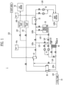
- FIGS. 1 and 2 are conceptual diagrams of a gas treatment system according to one embodiment of the present invention.
- FIG. 1 shows a state in which a load of a main engine E1 is greater than or equal to a preset value
- FIG. 2 shows a state in which the load of the main engine E1 is smaller than the preset value or the main engine E1 does not operate.
- a gas treatment system 1 includes a liquefied gas storage tank 10, a coolant pump 21, a coolant cooler 22, a fresh water generator 23, a heat exchanger 30, a booster pump 41, a backup heater 42, and a gas separator 43.
- the coolant pump 21, the coolant cooler 22, the fresh water generator 23, the heat exchanger 30, the booster pump 41, the backup heater 42, and the gas separator 43 may be provided along a coolant circulation line L20, and although will be described below, the coolant pump 21, the coolant cooler 22, and the fresh water generator 23 may be provided in a first closed loop, and the heat exchanger 30, the booster pump 41, the backup heater 42, and the gas separator 43 may be provided in a second closed loop.
- the liquefied gas storage tank 10 stores a liquefied gas.
- the liquefied gas storage tank 10 is an independent tank according to international maritime organization (IMO) regulations and may be a Type A, B, C, or the like or may also be a membrane type tank.
- IMO international maritime organization
- the liquefied gas storage tank 10 may store the liquefied gas at cryogenic temperature, but due to the influence of external heat, the liquefied gas naturally evaporates to generate the evaporation gas. At this time, since the evaporation gas causes an increase in an internal pressure of the liquefied gas storage tank 10, the evaporation gas may be discharged to the outside in order to maintain the stable internal pressure of the liquefied gas storage tank 10.
- the liquefied gas (and/or the evaporation gas) accommodated in the liquefied gas storage tank 10 may be supplied to and used in engines E1 and E2, which are driving targets.
- the engines E1 and E2 are the main engine E1 (ME-GI, X-DF, ME-LGI, ME-GIE, or the like) for propulsion of a vessel, an auxiliary engine E2 as a power generation engine for covering a power load in the vessel, and the like.
- a fuel supply line L30 may be provided to supply the liquefied gas stored in the liquefied gas storage tank 10 to the engines E1 and E2, and specifically, the fuel supply line L30 may include a first fuel supply line L31 for supplying the liquefied gas to the main engine E1 and a second fuel supply line L32 for supplying the liquefied gas to the auxiliary engine E2.
- the heat exchanger 30 may be provided on the first fuel supply line L31
- the second fuel supply line L32 may be branched off from the first fuel supply line L31 from a downstream of the heat exchanger 30 and connected to the auxiliary engine E2.
- a valve (not shown), a gas valve unit (not shown) for controlling a flow rate of the liquefied gas, or the like may be provided on the first and second fuel supply lines L31 and L32.
- the coolant circulation line L20 may include a first coolant circulation line L20a circulating through the heat exchanger 30 and a second coolant circulation line L20b circulating through the main engine E1, and the first coolant circulation line L20a and the second coolant circulation line L20b may be mutually connected to form one closed loop.
- the first and second coolant circulation lines L20a and L20b may be provided to separate the flow of the coolant.
- the coolant pump 21, the coolant cooler 22, and the fresh water generator 23 provided at the main engine E1 (a second coolant circulation line L20b) on the coolant circulation line L20 will be first described.
- the coolant pump 21 may pump the coolant so that the coolant circulates along the coolant circulation line L20.
- the coolant circulation line L20 provided with the coolant pump 21 may form a closed loop so that the coolant circulates through the main engine E1 that uses a liquefied gas as fuel and the heat exchanger 30 to be described below.
- the coolant described herein may also be used for the auxiliary engine E2 in addition to the main engine E1.
- the coolant pump 21 may be disposed at an upstream of the main engine E1 on the coolant circulation line L20, and a plurality of coolant pumps 21 may be provided in parallel and provided to be mutually backed-up.
- the coolant pump 21 may allow the coolant cooled by the coolant cooler 22 to be described below to be supplied to the main engine E1, and the coolant pump 21 may be provided at a downstream of the coolant cooler 22 as shown in the drawing. Alternatively, unlike the drawing, the coolant pump 21 may also be provided at an upstream of the coolant cooler 22 on the coolant circulation line L20.
- the coolant cooler 22 cools the coolant that is heated while passing the main engine E1.
- the coolant cooler 22 may cool the coolant using various refrigerants, such as seawater, fresh water, and air, and may be disposed at an upstream of the coolant pump 21 on the coolant circulation line L20 or the like.
- the coolant circulation line L20 may be provided so that at least some of the coolant may bypass the coolant cooler 22, and thus a temperature of the coolant may be adjusted at the downstream of the coolant cooler 22.
- a temperature at the downstream of the coolant cooler 22 increases, and conversely, when the amount of the coolant bypassing the coolant cooler 22 is reduced, a temperature at the downstream of the coolant cooler 22 is decreases.
- the amount of the coolant bypassing the coolant cooler 22 may be determined depending on the temperature of the coolant transmitted to the coolant cooler 22 or may also be determined depending on the load of the main engine E1 that influences the temperature of the coolant.
- the fresh water generator 23 generates fresh water using waste heat of the coolant.
- the fresh water generator 23 may generate steam by heating seawater or the like using high-temperature coolant discharged from the main engine E1 and generate fresh water from the steam.
- the fresh water generator 23 may use all methods capable of heating fresh water using coolant.
- the fresh water generator 23 may transmit fresh water to a fresh water tank (not shown), and the coolant may bypass the fresh water generator 23 when an amount of the stored fresh water tank is sufficient or when additional generation of the fresh water is unnecessary.
- the coolant circulation line L20 may be provided to allow the coolant to bypass the fresh water generator 23.
- the amount of the coolant bypassing the fresh water generator 23 on the coolant circulation line L20 may be adjusted to adjust the temperature of the coolant at a downstream of the fresh water generator 23.
- the fresh water generator 23 may be provided at the upstream of the coolant cooler 22 on the coolant circulation line L20 to allow the high-temperature coolant discharged from the main engine E1 to be primarily cooled through the fresh water generator 23 and then secondarily cooled by the coolant cooler 22.
- First and second branch lines L21 and L22 may be provided on the coolant circulation line L20, and the coolant may circulate in the closed loop formed by the coolant circulation line L20 or circulate in the first and second closed loops formed through the first and second branch lines L21 and L22. This will be described in detail below.
- the heat exchanger 30 heats the liquefied gas and supplies the heated liquefied gas to the main engine E1, the auxiliary engine E2, and the like.
- the heat exchanger 30 is a component for heat-exchanging a heat medium with a liquefied gas and may be provided in a shell and tube, a bath type, a printed circuit heat exchanger (PCHE) type, or the like, but the type is not limited thereto.
- the heat exchanger 30 may be provided on the first fuel supply line L31 and may be provided with a flow path through which the liquefied gas flows and a flow path through which the heating medium flows.
- the liquefied gas is heated in the heat exchanger 30 to correspond to temperatures required by the engines E1 and E2 and then transmitted to the engines E1 and E2, and the high-temperature heating medium flows into the heat exchanger 30, then is cooled by the liquefied gas, and then is discharged from the heat exchanger 30.
- the heating medium may be the coolant used in the engines E1 and E2.
- the heat exchanger 30 may be provided in a type that directly exchanges heat with a liquefied gas using coolant, and the coolant may be one used in the main engine E1 of the engines E1 and E2. Therefore, the heat exchanger 30 may have one side connected to the first fuel supply line L31 and the other side connected to the coolant circulation line L20 through which the coolant flows.
- the present invention may also include an indirect heat exchange method in which the heating medium of the heat exchanger 30 is heated using the coolant rather than a direct heat exchange method in which the coolant directly flows through the heat exchanger 30.
- one heat exchanger 30 may be provided or two or more heat exchangers 30 may be provided.
- the plurality of heat exchangers 30 may be provided in series and/or in parallel, and a separate heat exchanger 30 may also be assigned to each of the main engine E1 and the auxiliary engine E2.
- the booster pump 41, the backup heater 42, and the gas separator 43 provided at the heat exchanger 30 (a first coolant circulation line L20a) on the coolant circulation line L20 will be described.
- the booster pump 41 pumps the high-temperature coolant discharged from the main engine E1 to the heat exchanger 30.
- the booster pump 41 may be disposed at an upstream of the heat exchanger 30 on the coolant circulation line L20 and may have a function similar to that of the coolant pump 21 described above.
- the booster pump 41 may pressurize the coolant in response to the pressure of the liquefied gas flowing into the heat exchanger 30 in order to minimize a pressure difference between the liquefied gas and the coolant in the heat exchanger 30.
- a discharge pressure of the booster pump 41 may be relatively higher than a discharge pressure of the coolant pump 21.
- a plurality of booster pumps 41 may be provided in parallel or in series, and when the booster pumps 41 are provided in parallel, the coolant may be simultaneously pumped by the plurality of booster pumps 41, and thus a load of each booster pump 41 may be reduced.
- the backup heater 42 heats at least some of the coolant transmitted to the heat exchanger 30.
- the backup heater 42 may heat the coolant using a separate heat source so that the coolant has a temperature sufficient to heat the liquefied gas in the heat exchanger 30.
- the heat source may be seawater, fresh water, steam, or the like, but is not limited thereto.
- the backup heater 42 may be used to cope with a case in which as the load of the main engine E1 is reduced, the temperature of the coolant is reduced and thus heat required for sufficiently heating the liquefied gas in the heat exchanger 30 becomes insufficient, a case in which the temperature of the coolant is reduced due to an outside air temperature, a case in which the main engine E1 is stopped, thereby not heating the coolant, and the like.
- the backup heater 42 may be disposed on a downstream of the booster pump 41 on the coolant circulation line L20, but a position of the backup heater 42 is not limited thereto, and the backup heater 42 may also be provided on the first branch line L21 to be described below.
- the gas separator 43 separates a gas that may be included in the low-temperature coolant discharged from the heat exchanger 30.
- the gas separator 43 may be provided at the downstream of the heat exchanger 30 on the coolant circulation line L20 and, when a gas leaks from the heat exchanger 30 and is mixed with the coolant, may detect and separate the gas.
- a gas detector (not shown) may be provided in the gas separator 43, and since the gas separated by the gas separator 43 is explosive, the gas may be safely discharged to the outside through a vent line L25.
- the supply of the liquefied gas to the heat exchanger 30 may be blocked to prevent additional leakage of the liquefied gas, and the engines E1 and E2 may be stopped or switched to a mode in which oil fuel or the like rather than the liquefied gas is consumed.
- the engines E1 and E2 may be dual fuel engines capable of using gas fuel and/or oil fuel.
- the gas separator 43 may be disposed between the heat exchanger 30 and the booster pump 41 on the coolant circulation line L20 and may have a container shape that stores the coolant. Therefore, the gas separator 43 may have a partial expansion function on the coolant circulation line L20.
- coolant circulation line L20 and the first and second branch lines L21 and L22 will be described.
- the coolant circulation line L20 may be provided to allow the coolant to circulate through and supply to the main engine E1 and the heat exchanger 30, and the high-temperature coolant may be discharged from the main engine E1, then cooled to a low temperature while exchanging heat with the liquefied gas in the heat exchanger 30, and returned to the main engine E1.
- the coolant circulation line L20 is provided with the first branch line L21 for connecting both ends of the first coolant circulation line L20a to connect the upstream and the downstream of the heat exchanger 30 so that the coolant bypasses the main engine E1 and circulates through the heat exchanger 30.
- coolant circulation line L20 is provided with the second branch line L22 for connecting both ends of the second coolant circulation line L20b on the coolant circulation line L20 to connect the upstream and downstream of the main engine E1 so that the coolant circulates through the main engine E1 while bypassing the heat exchanger 30.
- first and second branch lines L21 and L22 together with the first and second coolant circulation lines L20a and L20b may form first and second closed loops provided independently.
- the coolant may circulate along a total of three closed loops.
- the coolant may pass the heat exchanger 30 and the main engine E1 while circulating along the entire coolant circulation line L20, bypass the main engine E1 and pass the heat exchanger 30 while circulating along the first coolant circulation line L20a and the first branch line L21, or bypass the heat exchanger 30 and pass the main engine E1 while circulating along the second coolant circulation line L20b and the second branch line L22.
- both the first and second branch lines L21 and L22 may be closed, and the coolant largely circulates along the entire coolant circulation line L20. Therefore, the coolant repeats a process of being heated in the main engine E1 and cooled in the heat exchanger 30.
- the coolant circulation line L20a may be provided with a heater bypass line L23 for allowing the coolant to bypass the backup heater 42 when the coolant is supplied to the heat exchanger 30 via the main engine E1 through the coolant circulation line L20.
- the coolant may be insufficiently heated in the main engine E1, and thus, in this case, the heater bypass line L23 may be blocked and the backup heater 42 may be used.
- the first branch line L21 is opened so that the coolant circulates in the first closed loop formed along the first coolant circulation line L20a and the first branch line L21.
- valves capable of blocking the flow of the coolant may be provided at a downstream of a branching point of the first branch line L21 and an upstream of a joining point of the first branch line L21 on the coolant circulation line L20 so that the coolant may circulate in the first closed loop.
- the booster pump 41, the backup heater 42, the heat exchanger 30, and the gas separator 43 are provided on the first closed loop, and the coolant is heated in the backup heater 43 and then supplied to the heat exchanger 30. Therefore, according to the present invention, it is possible to ensure stable heating of the liquefied gas in the heat exchanger 30 even when the coolant does not circulate through the main engine E1 or may not circulate therethrough.
- the auxiliary engine E2 is stably operated.
- the second branch line L22 is opened so that the coolant circulates in the second closed loop formed along the second coolant circulation line L20b and the second branch line L22.
- valves provided at an upstream of a branching point of the second branch line L22 and the upstream of a joining point of the second branch line L22 on the coolant circulation line L20 may be operated so that the coolant circulates in the second closed loop.
- the valve provided at the downstream of the branching point of the first branch line L21 on the coolant circulation line L20 may be the valve provided at the upstream of the joining point of the second branch line L22 on the coolant circulation line L20
- the valve provided at the upstream of the joining point of the first branch line L21 on the coolant circulation line L20 may be the valve provided at a downstream of the branching point of the second branch line L22 on the coolant circulation line L20.
- the present invention is not construed as being limited to the above-described arrangement of the valves, and a 2-way valve and/or a 3-way valve may be appropriately used.
- the coolant pump 21, the coolant cooler 22, and the fresh water generator 23 may be provided on the second closed loop, and the coolant may be heated in the main engine E1 and then cooled in the coolant cooler 22. Therefore, according to the present invention, it is possible to ensure the supply of the coolant to the main engine E1 when the coolant is not transmitted or may not be transmitted to the heat exchanger 30, thereby maintaining the stable operation of the main engine E1.
- Expansion tanks 44a and 44b are connected to the coolant circulation line L20.
- the expansion tanks 44a and 44b may be provided to adjust the pressure of the coolant flowing along the entire coolant circulation line L20.
- expansion tanks 44a and 44b are provided and respectively connected to the first closed loop and the second closed loop formed by the first and second branch lines L21 and L22, it is possible to perform coolant pressure adjustment in the first and second closed loops, thereby preventing overpressure in the first and second closed loops.
- one of the expansion tanks 44a and 44b may also be integrally connected to the first and second closed loops.
- the expansion tanks 44a and 44b may be provided to be respectively connected to the first and second coolant circulation lines L20a and L20b.
- the expansion tank 44a connected to the first coolant circulation line L20a is provided at a downstream of the gas separator 43 on the coolant circulation line L20 and the expansion tank 44a is branched off from the coolant circulation line L20, the coolant passing the gas separator 43 may flow without passing the expansion tank 44a.
- the pressure of the coolant increases at the downstream of the gas separator 43, the coolant may be naturally transmitted to the expansion tank 44a, and thus the pressure of the coolant may be reduced through the expansion tank 44a.
- the expansion tank 44b connected to the second coolant circulation line L20b may be provided to be connected between the coolant cooler 22 and the coolant pump 21 and the expansion tank 44b is branched off from the coolant circulation line L20, the coolant cooled in the coolant cooler 22 may bypass the expansion tank 44b and flow into the coolant pump 21. However, when overpressure occurs in the second closed loop, the coolant may be transmitted to the expansion tank 44b to maintain an introduction pressure of the coolant pump 21 at an appropriate level.
- the expansion tanks 44a and 44b may be connected by being branched off from the coolant circulation line L20 or the first and second branch lines L21 and L22 or provided on the coolant circulation line L20 and the first and second branch lines L21 and L22.
- the expansion tanks 44a and 44b are not necessarily limited to the form of a container and may include any form that performs a buffer function like a form in which a part of a line is expanded or the like.
- expansion tanks 44a and 44b By providing the expansion tanks 44a and 44b, according to the present invention, it is possible to secure an overpressure prevention function in the flow of the coolant in in both of a case in which the coolant circulates only in the first closed loop and a case in which the coolant circulates only in the second closed loop.
- a heat exchanger bypass line L24 for bypassing the heat exchanger 30 may be provided on the coolant circulation line L20 at the upstream of the heat exchanger 30. Therefore, since at least some of the coolant may not be cooled by the liquefied gas while bypassing the heat exchanger 30, the at least some of the coolant may be used to adjust the temperature of the coolant at the downstream of the heat exchanger 30.
- the flow to the heat exchanger bypass line L24 may be controlled according to variables, such as the flow rate or temperature of the liquefied gas and the flow rate and temperature of the coolant. For example, in order to prevent excessive heating of the liquefied gas when the temperature of the liquefied gas is relatively high, some of the coolant may be bypassed through the heat exchanger bypass line L24. On the other hand, when a low temperature of the liquefied gas is detected, the flow of the coolant on the heat exchanger bypass line L24 may be blocked.
- the coolant circulation line L20 forms the closed loop connecting both the main engine E1 and the heat exchanger 30
- the high-temperature coolant discharged from the main engine E1 may be transmitted to the heat exchanger 30 through the coolant circulation line L20.
- the low-temperature coolant discharged from the heat exchanger 30 may flow into the coolant cooler 22 after passing the gas separator 43 or the like along the coolant circulation line L20.
- the coolant flows into the coolant cooler 22, the coolant pump 21, and the main engine E1 along the coolant circulation line L20, at least some of the coolant may flow along the booster pump 41, the backup heater 42 (as necessary), the heat exchanger 30, and the gas separator 43 on the coolant circulation line L20 at the downstream of the main engine E1 and then may be transmitted back to the coolant cooler 22.
- This flow may be performed when the coolant is sufficiently heated in the main engine E1 as the main engine E1 normally operates.
- the high-temperature coolant heated while passing the main engine E1 is transmitted to the heat exchanger 30 along the coolant circulation line L20 to transmit the waste heat of the coolant to the liquefied gas of the heat exchanger 30.
- the load of the main engine E1 needs to be the preset value or more.
- the coolant may circulate along the entire coolant circulation line L20.
- at least some of the coolant on the coolant circulation line L20 may bypass the backup heater 42 through the heater bypass line L23 and flow into the heat exchanger 30.
- the coolant may be insufficiently heated even when the coolant passes the main engine E1. Therefore, in this case, the circulation of the coolant along the coolant circulation line L20 is similar to the above-described case, but the coolant flowing on the coolant circulation line L20 may be additionally heated through the backup heater 42 and then may flow into the heat exchanger 30.
- the coolant may not flow on the coolant circulation line L20.
- the first branch line L21 is opened by adjusting the valve, the coolant flows along the first closed loop formed by the first coolant circulation line L20a and the first branch line L21.
- the backup heater 42 may be used.
- the coolant may flow into the heat exchanger 30 after being heated through the backup heater 42 while circulating along the first coolant circulation line L20a and the first branch line L21.
- the heat exchanger 30 may stably heat the liquefied gas through the coolant without using the waste heat of the main engine E1.
Landscapes
- Engineering & Computer Science (AREA)
- Chemical & Material Sciences (AREA)
- Mechanical Engineering (AREA)
- Combustion & Propulsion (AREA)
- General Engineering & Computer Science (AREA)
- Ocean & Marine Engineering (AREA)
- Chemical Kinetics & Catalysis (AREA)
- General Chemical & Material Sciences (AREA)
- Oil, Petroleum & Natural Gas (AREA)
- Filling Or Discharging Of Gas Storage Vessels (AREA)
Abstract
Description
- The present invention relates to a gas treatment system and a vessel including the same.
- Vessels are a means of transportation for carrying a large amount of minerals, crude oil, natural gas, or several thousand or more containers and navigating the ocean and are made of steel and moves through thrust generated by the rotation of a propeller in a state of floating on a water plane by buoyancy.
- These vessels generate a thrust by driving an engine, a gas turbine, or the like, and in this case, the engine moves a piston using oil fuel, such as gasoline or diesel so that a crankshaft is rotated by a reciprocating motion of the piston, and a shaft connected to the crankshaft is rotated to drive the propeller, while the gas turbine uses a method of combusting fuel together with compressed air, rotating turbine blades through a temperature/pressure of the combustion air to generate power, and transmitting power to the propeller.
- However, recently, liquefied natural gas (LNG) carriers for carrying liquefied natural gas, which is a type of liquefied gas, use an LNG fuel supply method for driving targets, such as an engine and a turbine, using LNG as fuel, and since LNG is clean fuel and also has richer reserves than oil, the method using LNG as fuel for the driving targets is also applied to vessels other than the LNG carriers.
- However, compared to the conventional case of using oil fuel, such as diesel, since there are still many problems to be solved in the case of using LNG, which is gas fuel, the research and development for a technology of supplying LNG to driving targets in vessels using LNG, which is clean fuel, are continuously conducted.
- The present invention has been made in efforts to solve the problems of the related art and is directed to providing a gas treatment system and a vessel including the same, in which the use of energy may be reduced using waste heat of coolant heated by an engine for heating liquefied gas flowing into the engine.
- A gas treatment system according to one aspect of the present invention includes a first fuel supply line configured to supply fuel to a main engine, a second fuel supply line branched off from the first fuel supply line and configured to supply the fuel to an auxiliary engine, a heat exchanger provided on the first fuel supply line to heat the fuel, and a coolant circulation line of the main engine provided to supply a heat source to the heat exchanger, wherein the coolant circulation line is provided to be divided into a first coolant circulation line circulating through the heat exchanger and a second coolant circulation line circulating through the main engine.
- The gas treatment system may further include a first branch line connecting both ends of the first coolant circulation line to allow a coolant to bypass the main engine and circulate through the heat exchanger, and a second branch line connecting both ends of the second coolant circulation line to allow the coolant to circulate through the main engine while bypassing the heat exchanger.
- The gas treatment system may include a backup heater provided on the first coolant circulation line or the first branch line, wherein when a load of the main engine is less than a preset value or the coolant bypasses the main engine by the first branch line, the backup heater may heat the coolant and supply the heated coolant to the heat exchanger.
- The gas treatment system may further include a bypass line provided to bypass the backup heater when the coolant is supplied to the heat exchanger via the main engine through the coolant circulation line.
- When the main engine is stopped, the first branch line may allow the coolant to bypass the main engine and circulate through the heat exchanger.
- The coolant may pass the heat exchanger and the main engine while circulating along the entire coolant circulation line, bypass the main engine and pass the heat exchanger while circulating along the first coolant circulation line and the first branch line, or bypass the heat exchanger and pass the main engine while circulating along the second coolant circulation line and the second branch line.
- A first closed loop formed by the first coolant circulation line and the first branch line may be provided independently of a second closed loop formed by the second coolant circulation line and the second branch line.
- The gas treatment system may further include an expansion tank provided to adjust a pressure of the coolant flowing along the first closed loop or the second closed loop.
- A vessel according to one aspect of the present invention has the gas treatment system.
- A gas treatment system and a vessel including the same according to the present invention can heat liquefied gas using coolant used in a main engine, thereby implementing efficient vaporization of the liquefied gas and securing stable heating of the liquefied gas even when the main engine is stopped or the coolant is not sufficiently heated.
-
-
FIG. 1 is a conceptual diagram of a gas treatment system according to one embodiment of the present invention. -
FIG. 2 is a conceptual diagram of a gas treatment system according to one embodiment of the present invention. - Objects, specific advantages, and novel features of the present invention will become more apparent from the following detailed description and exemplary embodiments taken in conjunction with the accompanying drawings. In adding reference numerals to components of each drawing in the specification, it should be noted that the same components have the same numbers as much as possible even when they are shown in different drawings. In addition, in describing the present invention, when it is determined that a detailed description of related known technologies may unnecessarily obscure the gist of the present invention, the detailed description will be omitted.
- Hereinafter, a fuel may be a liquefied gas, the liquefied gas may be liquefied petroleum gas (LPG), LNG, ethane, or the like and may exemplarily mean liquefied natural gas (LNG), and evaporation gas may be boil off gas (BOG), such as natural vaporized LNG. In addition, the liquefied gas below may be used as the term including all of a liquid state, a naturally vaporized or forcibly vaporized gas state, and the like, but it should be noted that the evaporation gas may be used as the term meaning gas that is naturally vaporized in a liquefied gas storage tank.
- For reference, the present invention includes a vessel having a gas treatment system to be described below. In this case, it should be noted that the vessel is a general merchant ship or an expression including offshore plants, such as a floating LNG (FLNG) plant and a floating storage re-gasification unit (FSRU), and furthermore, may also be replaced with plants or the like installed on land.
- Hereinafter, exemplary embodiments of the present invention will be described in detail with reference to the accompanying drawings.
-
FIGS. 1 and2 are conceptual diagrams of a gas treatment system according to one embodiment of the present invention. - For reference,
FIG. 1 shows a state in which a load of a main engine E1 is greater than or equal to a preset value, andFIG. 2 shows a state in which the load of the main engine E1 is smaller than the preset value or the main engine E1 does not operate. - Referring to
FIGS. 1 and2 , agas treatment system 1 according to one embodiment of the present invention includes a liquefiedgas storage tank 10, acoolant pump 21, acoolant cooler 22, afresh water generator 23, aheat exchanger 30, abooster pump 41, abackup heater 42, and agas separator 43. - In this case, the
coolant pump 21, thecoolant cooler 22, thefresh water generator 23, theheat exchanger 30, thebooster pump 41, thebackup heater 42, and thegas separator 43 may be provided along a coolant circulation line L20, and although will be described below, thecoolant pump 21, thecoolant cooler 22, and thefresh water generator 23 may be provided in a first closed loop, and theheat exchanger 30, thebooster pump 41, thebackup heater 42, and thegas separator 43 may be provided in a second closed loop. - The liquefied
gas storage tank 10 stores a liquefied gas. The liquefiedgas storage tank 10 is an independent tank according to international maritime organization (IMO) regulations and may be a Type A, B, C, or the like or may also be a membrane type tank. - The liquefied
gas storage tank 10 may store the liquefied gas at cryogenic temperature, but due to the influence of external heat, the liquefied gas naturally evaporates to generate the evaporation gas. At this time, since the evaporation gas causes an increase in an internal pressure of the liquefiedgas storage tank 10, the evaporation gas may be discharged to the outside in order to maintain the stable internal pressure of the liquefiedgas storage tank 10. - The liquefied gas (and/or the evaporation gas) accommodated in the liquefied
gas storage tank 10 may be supplied to and used in engines E1 and E2, which are driving targets. In this case, the engines E1 and E2 are the main engine E1 (ME-GI, X-DF, ME-LGI, ME-GIE, or the like) for propulsion of a vessel, an auxiliary engine E2 as a power generation engine for covering a power load in the vessel, and the like. - A fuel supply line L30 may be provided to supply the liquefied gas stored in the liquefied
gas storage tank 10 to the engines E1 and E2, and specifically, the fuel supply line L30 may include a first fuel supply line L31 for supplying the liquefied gas to the main engine E1 and a second fuel supply line L32 for supplying the liquefied gas to the auxiliary engine E2. In this case, theheat exchanger 30 may be provided on the first fuel supply line L31, and the second fuel supply line L32 may be branched off from the first fuel supply line L31 from a downstream of theheat exchanger 30 and connected to the auxiliary engine E2. In addition, a valve (not shown), a gas valve unit (not shown) for controlling a flow rate of the liquefied gas, or the like may be provided on the first and second fuel supply lines L31 and L32. - The coolant circulation line L20 may include a first coolant circulation line L20a circulating through the
heat exchanger 30 and a second coolant circulation line L20b circulating through the main engine E1, and the first coolant circulation line L20a and the second coolant circulation line L20b may be mutually connected to form one closed loop. In addition, the first and second coolant circulation lines L20a and L20b may be provided to separate the flow of the coolant. - Hereinafter, the
coolant pump 21, thecoolant cooler 22, and thefresh water generator 23 provided at the main engine E1 (a second coolant circulation line L20b) on the coolant circulation line L20 will be first described. - The
coolant pump 21 may pump the coolant so that the coolant circulates along the coolant circulation line L20. The coolant circulation line L20 provided with thecoolant pump 21 may form a closed loop so that the coolant circulates through the main engine E1 that uses a liquefied gas as fuel and theheat exchanger 30 to be described below. However, the coolant described herein may also be used for the auxiliary engine E2 in addition to the main engine E1. - The
coolant pump 21 may be disposed at an upstream of the main engine E1 on the coolant circulation line L20, and a plurality ofcoolant pumps 21 may be provided in parallel and provided to be mutually backed-up. - The
coolant pump 21 may allow the coolant cooled by thecoolant cooler 22 to be described below to be supplied to the main engine E1, and thecoolant pump 21 may be provided at a downstream of thecoolant cooler 22 as shown in the drawing. Alternatively, unlike the drawing, thecoolant pump 21 may also be provided at an upstream of thecoolant cooler 22 on the coolant circulation line L20. - The
coolant cooler 22 cools the coolant that is heated while passing the main engine E1. Thecoolant cooler 22 may cool the coolant using various refrigerants, such as seawater, fresh water, and air, and may be disposed at an upstream of thecoolant pump 21 on the coolant circulation line L20 or the like. - The coolant circulation line L20 may be provided so that at least some of the coolant may bypass the
coolant cooler 22, and thus a temperature of the coolant may be adjusted at the downstream of thecoolant cooler 22. In other words, when an amount of the coolant bypassing thecoolant cooler 22 among the coolant flowing through the upstream of thecoolant cooler 22 increases, a temperature at the downstream of thecoolant cooler 22 increases, and conversely, when the amount of the coolant bypassing thecoolant cooler 22 is reduced, a temperature at the downstream of thecoolant cooler 22 is decreases. - The amount of the coolant bypassing the
coolant cooler 22 may be determined depending on the temperature of the coolant transmitted to thecoolant cooler 22 or may also be determined depending on the load of the main engine E1 that influences the temperature of the coolant. - The
fresh water generator 23 generates fresh water using waste heat of the coolant. Thefresh water generator 23 may generate steam by heating seawater or the like using high-temperature coolant discharged from the main engine E1 and generate fresh water from the steam. Of course, in addition to the above, thefresh water generator 23 may use all methods capable of heating fresh water using coolant. - The
fresh water generator 23 may transmit fresh water to a fresh water tank (not shown), and the coolant may bypass thefresh water generator 23 when an amount of the stored fresh water tank is sufficient or when additional generation of the fresh water is unnecessary. - In other words, as described in the
coolant cooler 22, the coolant circulation line L20 may be provided to allow the coolant to bypass thefresh water generator 23. In addition, since the temperature of the coolant may be reduced as the coolant passes thefresh water generator 23, the amount of the coolant bypassing thefresh water generator 23 on the coolant circulation line L20 may be adjusted to adjust the temperature of the coolant at a downstream of thefresh water generator 23. - The
fresh water generator 23 may be provided at the upstream of thecoolant cooler 22 on the coolant circulation line L20 to allow the high-temperature coolant discharged from the main engine E1 to be primarily cooled through thefresh water generator 23 and then secondarily cooled by thecoolant cooler 22. - First and second branch lines L21 and L22 may be provided on the coolant circulation line L20, and the coolant may circulate in the closed loop formed by the coolant circulation line L20 or circulate in the first and second closed loops formed through the first and second branch lines L21 and L22. This will be described in detail below.
- The
heat exchanger 30 heats the liquefied gas and supplies the heated liquefied gas to the main engine E1, the auxiliary engine E2, and the like. Theheat exchanger 30 is a component for heat-exchanging a heat medium with a liquefied gas and may be provided in a shell and tube, a bath type, a printed circuit heat exchanger (PCHE) type, or the like, but the type is not limited thereto. - The
heat exchanger 30 may be provided on the first fuel supply line L31 and may be provided with a flow path through which the liquefied gas flows and a flow path through which the heating medium flows. The liquefied gas is heated in theheat exchanger 30 to correspond to temperatures required by the engines E1 and E2 and then transmitted to the engines E1 and E2, and the high-temperature heating medium flows into theheat exchanger 30, then is cooled by the liquefied gas, and then is discharged from theheat exchanger 30. - In the embodiment, the heating medium may be the coolant used in the engines E1 and E2. The
heat exchanger 30 may be provided in a type that directly exchanges heat with a liquefied gas using coolant, and the coolant may be one used in the main engine E1 of the engines E1 and E2. Therefore, theheat exchanger 30 may have one side connected to the first fuel supply line L31 and the other side connected to the coolant circulation line L20 through which the coolant flows. - Of course, the present invention may also include an indirect heat exchange method in which the heating medium of the
heat exchanger 30 is heated using the coolant rather than a direct heat exchange method in which the coolant directly flows through theheat exchanger 30. - As shown in the drawing, one
heat exchanger 30 may be provided or two ormore heat exchangers 30 may be provided. When a plurality ofheat exchangers 30 are provided, the plurality ofheat exchangers 30 may be provided in series and/or in parallel, and aseparate heat exchanger 30 may also be assigned to each of the main engine E1 and the auxiliary engine E2. - Hereinafter, the
booster pump 41, thebackup heater 42, and thegas separator 43 provided at the heat exchanger 30 (a first coolant circulation line L20a) on the coolant circulation line L20 will be described. - The
booster pump 41 pumps the high-temperature coolant discharged from the main engine E1 to theheat exchanger 30. Thebooster pump 41 may be disposed at an upstream of theheat exchanger 30 on the coolant circulation line L20 and may have a function similar to that of thecoolant pump 21 described above. - The
booster pump 41 may pressurize the coolant in response to the pressure of the liquefied gas flowing into theheat exchanger 30 in order to minimize a pressure difference between the liquefied gas and the coolant in theheat exchanger 30. In this case, a discharge pressure of thebooster pump 41 may be relatively higher than a discharge pressure of thecoolant pump 21. - Like the
coolant pump 21, a plurality of booster pumps 41 may be provided in parallel or in series, and when the booster pumps 41 are provided in parallel, the coolant may be simultaneously pumped by the plurality of booster pumps 41, and thus a load of eachbooster pump 41 may be reduced. - The
backup heater 42 heats at least some of the coolant transmitted to theheat exchanger 30. Thebackup heater 42 may heat the coolant using a separate heat source so that the coolant has a temperature sufficient to heat the liquefied gas in theheat exchanger 30. In this case, the heat source may be seawater, fresh water, steam, or the like, but is not limited thereto. - The
backup heater 42 may be used to cope with a case in which as the load of the main engine E1 is reduced, the temperature of the coolant is reduced and thus heat required for sufficiently heating the liquefied gas in theheat exchanger 30 becomes insufficient, a case in which the temperature of the coolant is reduced due to an outside air temperature, a case in which the main engine E1 is stopped, thereby not heating the coolant, and the like. - The
backup heater 42 may be disposed on a downstream of thebooster pump 41 on the coolant circulation line L20, but a position of thebackup heater 42 is not limited thereto, and thebackup heater 42 may also be provided on the first branch line L21 to be described below. - The
gas separator 43 separates a gas that may be included in the low-temperature coolant discharged from theheat exchanger 30. Thegas separator 43 may be provided at the downstream of theheat exchanger 30 on the coolant circulation line L20 and, when a gas leaks from theheat exchanger 30 and is mixed with the coolant, may detect and separate the gas. To this end, a gas detector (not shown) may be provided in thegas separator 43, and since the gas separated by thegas separator 43 is explosive, the gas may be safely discharged to the outside through a vent line L25. - When the
gas separator 43 detects the gas that is mixed with the coolant, the supply of the liquefied gas to theheat exchanger 30 may be blocked to prevent additional leakage of the liquefied gas, and the engines E1 and E2 may be stopped or switched to a mode in which oil fuel or the like rather than the liquefied gas is consumed. For the latter case, the engines E1 and E2 may be dual fuel engines capable of using gas fuel and/or oil fuel. - The
gas separator 43 may be disposed between theheat exchanger 30 and thebooster pump 41 on the coolant circulation line L20 and may have a container shape that stores the coolant. Therefore, thegas separator 43 may have a partial expansion function on the coolant circulation line L20. - Hereinafter, the coolant circulation line L20 and the first and second branch lines L21 and L22 will be described.
- The coolant circulation line L20 may be provided to allow the coolant to circulate through and supply to the main engine E1 and the
heat exchanger 30, and the high-temperature coolant may be discharged from the main engine E1, then cooled to a low temperature while exchanging heat with the liquefied gas in theheat exchanger 30, and returned to the main engine E1. - In this case, the coolant circulation line L20 is provided with the first branch line L21 for connecting both ends of the first coolant circulation line L20a to connect the upstream and the downstream of the
heat exchanger 30 so that the coolant bypasses the main engine E1 and circulates through theheat exchanger 30. - In addition, the coolant circulation line L20 is provided with the second branch line L22 for connecting both ends of the second coolant circulation line L20b on the coolant circulation line L20 to connect the upstream and downstream of the main engine E1 so that the coolant circulates through the main engine E1 while bypassing the
heat exchanger 30. - In this case, the first and second branch lines L21 and L22 together with the first and second coolant circulation lines L20a and L20b may form first and second closed loops provided independently. With this configuration, the coolant may circulate along a total of three closed loops.
- Specifically, the coolant may pass the
heat exchanger 30 and the main engine E1 while circulating along the entire coolant circulation line L20, bypass the main engine E1 and pass theheat exchanger 30 while circulating along the first coolant circulation line L20a and the first branch line L21, or bypass theheat exchanger 30 and pass the main engine E1 while circulating along the second coolant circulation line L20b and the second branch line L22. - When there is no problem in the operations of the main engine E1 and the
heat exchanger 30, both the first and second branch lines L21 and L22 may be closed, and the coolant largely circulates along the entire coolant circulation line L20. Therefore, the coolant repeats a process of being heated in the main engine E1 and cooled in theheat exchanger 30. - In particular, in this case, since the coolant may be heated to a sufficient temperature by the main engine E1 that operates with a normal load, additional heating by the
backup heater 42 may be unnecessary. Therefore, the coolant circulation line L20a may be provided with a heater bypass line L23 for allowing the coolant to bypass thebackup heater 42 when the coolant is supplied to theheat exchanger 30 via the main engine E1 through the coolant circulation line L20. - However, when the load of the main engine E1 is reduced to the preset value or less, the coolant may be insufficiently heated in the main engine E1, and thus, in this case, the heater bypass line L23 may be blocked and the
backup heater 42 may be used. - On the other hand, like a case in which the main engine E1 is stopped, when the coolant may not circulate through the main engine E1 or has low need to circulate therethrough, according to the present invention, the first branch line L21 is opened so that the coolant circulates in the first closed loop formed along the first coolant circulation line L20a and the first branch line L21.
- At this time, valves (not shown) capable of blocking the flow of the coolant may be provided at a downstream of a branching point of the first branch line L21 and an upstream of a joining point of the first branch line L21 on the coolant circulation line L20 so that the coolant may circulate in the first closed loop.
- The
booster pump 41, thebackup heater 42, theheat exchanger 30, and thegas separator 43 are provided on the first closed loop, and the coolant is heated in thebackup heater 43 and then supplied to theheat exchanger 30. Therefore, according to the present invention, it is possible to ensure stable heating of the liquefied gas in theheat exchanger 30 even when the coolant does not circulate through the main engine E1 or may not circulate therethrough. - Therefore, according to the present invention, in the system in which the main engine E1 and the auxiliary engine E2 share one
heat exchanger 30, even when a problem occurs in heating the coolant by the main engine E1, the auxiliary engine E2 is stably operated. - On the other hand, like a case in which leakage of the gas is detected by the
gas separator 43 or a case in which fuel other than the liquefied gas is supplied to the engines E1 and E2, when the use of theheat exchanger 30 is undesirable, according to the present invention, the second branch line L22 is opened so that the coolant circulates in the second closed loop formed along the second coolant circulation line L20b and the second branch line L22. - At this time, as described above, valves provided at an upstream of a branching point of the second branch line L22 and the upstream of a joining point of the second branch line L22 on the coolant circulation line L20 may be operated so that the coolant circulates in the second closed loop.
- For reference, the valve provided at the downstream of the branching point of the first branch line L21 on the coolant circulation line L20 may be the valve provided at the upstream of the joining point of the second branch line L22 on the coolant circulation line L20, and the valve provided at the upstream of the joining point of the first branch line L21 on the coolant circulation line L20 may be the valve provided at a downstream of the branching point of the second branch line L22 on the coolant circulation line L20.
- Of course, the present invention is not construed as being limited to the above-described arrangement of the valves, and a 2-way valve and/or a 3-way valve may be appropriately used.
- The
coolant pump 21, thecoolant cooler 22, and thefresh water generator 23 may be provided on the second closed loop, and the coolant may be heated in the main engine E1 and then cooled in thecoolant cooler 22. Therefore, according to the present invention, it is possible to ensure the supply of the coolant to the main engine E1 when the coolant is not transmitted or may not be transmitted to theheat exchanger 30, thereby maintaining the stable operation of the main engine E1. -
Expansion tanks expansion tanks - As a plurality of
expansion tanks expansion tanks - In the former case, the
expansion tanks expansion tank 44a connected to the first coolant circulation line L20a is provided at a downstream of thegas separator 43 on the coolant circulation line L20 and theexpansion tank 44a is branched off from the coolant circulation line L20, the coolant passing thegas separator 43 may flow without passing theexpansion tank 44a. However, when the pressure of the coolant increases at the downstream of thegas separator 43, the coolant may be naturally transmitted to theexpansion tank 44a, and thus the pressure of the coolant may be reduced through theexpansion tank 44a. - On the other hand, since the
expansion tank 44b connected to the second coolant circulation line L20b may be provided to be connected between thecoolant cooler 22 and thecoolant pump 21 and theexpansion tank 44b is branched off from the coolant circulation line L20, the coolant cooled in thecoolant cooler 22 may bypass theexpansion tank 44b and flow into thecoolant pump 21. However, when overpressure occurs in the second closed loop, the coolant may be transmitted to theexpansion tank 44b to maintain an introduction pressure of thecoolant pump 21 at an appropriate level. - The
expansion tanks expansion tanks - By providing the
expansion tanks - Additionally, a heat exchanger bypass line L24 for bypassing the
heat exchanger 30 may be provided on the coolant circulation line L20 at the upstream of theheat exchanger 30. Therefore, since at least some of the coolant may not be cooled by the liquefied gas while bypassing theheat exchanger 30, the at least some of the coolant may be used to adjust the temperature of the coolant at the downstream of theheat exchanger 30. - The flow to the heat exchanger bypass line L24 may be controlled according to variables, such as the flow rate or temperature of the liquefied gas and the flow rate and temperature of the coolant. For example, in order to prevent excessive heating of the liquefied gas when the temperature of the liquefied gas is relatively high, some of the coolant may be bypassed through the heat exchanger bypass line L24. On the other hand, when a low temperature of the liquefied gas is detected, the flow of the coolant on the heat exchanger bypass line L24 may be blocked.
- Hereinafter, various flows of the coolant shown in the embodiment will be described, and as shown in
FIG. 1 , a case in which the coolant flows along the coolant circulation line L20 will be first described. - Referring to
FIG. 1 , as described above, since the coolant circulation line L20 forms the closed loop connecting both the main engine E1 and theheat exchanger 30, the high-temperature coolant discharged from the main engine E1 may be transmitted to theheat exchanger 30 through the coolant circulation line L20. Then, the low-temperature coolant discharged from theheat exchanger 30 may flow into thecoolant cooler 22 after passing thegas separator 43 or the like along the coolant circulation line L20. - According to this flow, while the coolant flows into the
coolant cooler 22, thecoolant pump 21, and the main engine E1 along the coolant circulation line L20, at least some of the coolant may flow along thebooster pump 41, the backup heater 42 (as necessary), theheat exchanger 30, and thegas separator 43 on the coolant circulation line L20 at the downstream of the main engine E1 and then may be transmitted back to thecoolant cooler 22. - This flow may be performed when the coolant is sufficiently heated in the main engine E1 as the main engine E1 normally operates. In other words, in the embodiment, the high-temperature coolant heated while passing the main engine E1 is transmitted to the
heat exchanger 30 along the coolant circulation line L20 to transmit the waste heat of the coolant to the liquefied gas of theheat exchanger 30. - In order to sufficiently heat the coolant, the load of the main engine E1 needs to be the preset value or more. In other words, when the load of the main engine E1 is the preset value or more (or when a speed of the vessel is a preset speed or higher), the coolant may circulate along the entire coolant circulation line L20. In this case, since the coolant is sufficiently heated in the main engine E1, at least some of the coolant on the coolant circulation line L20 may bypass the
backup heater 42 through the heater bypass line L23 and flow into theheat exchanger 30. - On the other hand, when the load of the main engine E1 is less than the preset value (when the speed of the vessel is lower than the preset speed), the coolant may be insufficiently heated even when the coolant passes the main engine E1. Therefore, in this case, the circulation of the coolant along the coolant circulation line L20 is similar to the above-described case, but the coolant flowing on the coolant circulation line L20 may be additionally heated through the
backup heater 42 and then may flow into theheat exchanger 30. - Hereinafter, as shown in
FIG. 2 , a case in which the coolant flows along the first closed loop formed by the coolant circulation line L20 and the first branch line L21 will be described. - Referring to
FIG. 2 , when the main engine E1 is stopped to anchor the vessel, the coolant may not flow on the coolant circulation line L20. At this time, since the first branch line L21 is opened by adjusting the valve, the coolant flows along the first closed loop formed by the first coolant circulation line L20a and the first branch line L21. - However, in this case, since the coolant may not be heated by the main engine E1, the
backup heater 42 may be used. In other words, the coolant may flow into theheat exchanger 30 after being heated through thebackup heater 42 while circulating along the first coolant circulation line L20a and the first branch line L21. - In addition, in this case, as described above, since the pressure of the coolant may be adjusted through the
expansion tanks gas separator 43 and the like on the coolant circulation line L20, theheat exchanger 30 may stably heat the liquefied gas through the coolant without using the waste heat of the main engine E1. - As described above, in the embodiment, by heating the liquefied gas supplied to the engines E1 and E2 using the coolant of the main engine E1, controlling the flow of the coolant according to the load and operation of the main engine E1, and appropriately using the
backup heater 42, it is possible to secure the operation stability of the power generation engine through the stable heating of the liquefied gas. - Although the present invention has been described above in detail through specific embodiments, this is to specifically describe the present invention, the present invention is not limited thereto, and it will be apparent that modifications or improvements thereof are possible by those skilled in the art without departing from the technical spirit of the present invention.
- All simple modifications or changes of the present invention fall within the scope of the present invention, and the specific scope of the present invention will be clarified by the appended claims.
Claims (9)
- A gas treatment system comprising:a first fuel supply line configured to supply fuel to a main engine;a second fuel supply line branched off from the first fuel supply line and configured to supply the fuel to an auxiliary engine;a heat exchanger provided on the first fuel supply line to heat the fuel; anda coolant circulation line of the main engine provided to supply a heat source to the heat exchanger,wherein the coolant circulation line is provided to be divided into a first coolant circulation line circulating through the heat exchanger and a second coolant circulation line circulating through the main engine.
- The gas treatment system of claim 1, further comprising:a first branch line connecting both ends of the first coolant circulation line to allow a coolant to bypass the main engine and circulate through the heat exchanger; anda second branch line connecting both ends of the second coolant circulation line to allow the coolant to circulate through the main engine while bypassing the heat exchanger.
- The gas treatment system of claim 2, comprising a backup heater provided on the first coolant circulation line or the first branch line,
wherein, when a load of the main engine is less than a preset value or the coolant bypasses the main engine by the first branch line, the backup heater heats the coolant and supplies the heated coolant to the heat exchanger. - The gas treatment system of claim 3, further comprising a bypass line provided to bypass the backup heater when the coolant is supplied to the heat exchanger via the main engine through the coolant circulation line.
- The gas treatment system of claim 2, wherein, when the main engine is stopped, the first branch line allows the coolant to bypass the main engine and circulate through the heat exchanger.
- The gas treatment system of claim 2, wherein the coolant passes the heat exchanger and the main engine while circulating along the entire coolant circulation line,bypasses the main engine and passes the heat exchanger while circulating along the first coolant circulation line and the first branch line, orbypasses the heat exchanger and passes the main engine while circulating along the second coolant circulation line and the second branch line.
- The gas treatment system of claim 6, wherein a first closed loop formed by the first coolant circulation line and the first branch line is provided independently of a second closed loop formed by the second coolant circulation line and the second branch line.
- The gas treatment system of claim 7, further comprising an expansion tank provided to adjust a pressure of the coolant flowing along the first closed loop or the second closed loop.
- A vessel having the gas treatment system of any one of claims 1 to 8.
Applications Claiming Priority (2)
| Application Number | Priority Date | Filing Date | Title |
|---|---|---|---|
| KR20200130566 | 2020-10-08 | ||
| PCT/KR2021/013910 WO2022075810A1 (en) | 2020-10-08 | 2021-10-08 | Gas treatment system and ship including same |
Publications (2)
| Publication Number | Publication Date |
|---|---|
| EP4227208A1 true EP4227208A1 (en) | 2023-08-16 |
| EP4227208A4 EP4227208A4 (en) | 2024-10-23 |
Family
ID=81212048
Family Applications (1)
| Application Number | Title | Priority Date | Filing Date |
|---|---|---|---|
| EP21878060.9A Pending EP4227208A4 (en) | 2020-10-08 | 2021-10-08 | Gas treatment system and ship including same |
Country Status (3)
| Country | Link |
|---|---|
| EP (1) | EP4227208A4 (en) |
| KR (1) | KR102592518B1 (en) |
| CN (1) | CN116348368B (en) |
Family Cites Families (13)
| Publication number | Priority date | Publication date | Assignee | Title |
|---|---|---|---|---|
| KR20060049344A (en) * | 2003-10-25 | 2006-05-18 | 에스엔이씨엠에이 | Energy system using thermoelectric unit and natural gas stored in liquid phase |
| KR101434431B1 (en) * | 2012-01-18 | 2014-09-30 | 삼성중공업 주식회사 | System for Liquid Gas Fuel Supply and Ship Having The Same |
| CN103343718B (en) * | 2013-06-25 | 2016-06-01 | 上海佳豪船舶工程设计股份有限公司 | The LNG fuel main UTILIZATION OF VESIDUAL HEAT IN system of a kind of LNG fuels and energy boats and ships |
| KR20150017424A (en) * | 2013-07-19 | 2015-02-17 | 현대중공업 주식회사 | A Fuel Gas Supply System of Liquefied Gas |
| JP6310265B2 (en) * | 2014-02-06 | 2018-04-11 | 新潟原動機株式会社 | Liquefied gas supply system for ship propulsion gas fuel engine |
| KR101686505B1 (en) * | 2014-04-03 | 2016-12-14 | 대우조선해양 주식회사 | System and method for supplying fuel gas using a waste heat of engine cooling water |
| CN104595063B (en) * | 2015-01-28 | 2016-10-12 | 江苏科技大学 | Liquified natural gas gasification system based on double fuel engine of boat and ship cooling water heat |
| US20170159611A1 (en) * | 2015-12-04 | 2017-06-08 | Transfuels LLC | Liquid natural gas storage tank pressure control system |
| CN109863081B (en) * | 2016-10-05 | 2021-11-23 | 大宇造船海洋株式会社 | System and method for supplying fuel gas to ship |
| KR20190000277A (en) * | 2017-06-22 | 2019-01-02 | 현대중공업 주식회사 | Scrubber |
| KR102370604B1 (en) * | 2017-09-27 | 2022-03-04 | 대우조선해양 주식회사 | Fuel gas supply system and method for vessel |
| KR102138963B1 (en) * | 2017-12-19 | 2020-07-28 | 현대중공업 주식회사 | Gas treatment system and ship having the same |
| KR102189798B1 (en) * | 2019-02-08 | 2020-12-11 | 삼성중공업(주) | Liquefied gas re-gasification system of vessel |
-
2021
- 2021-10-08 KR KR1020210133568A patent/KR102592518B1/en active Active
- 2021-10-08 EP EP21878060.9A patent/EP4227208A4/en active Pending
- 2021-10-08 CN CN202180068874.9A patent/CN116348368B/en active Active
Also Published As
| Publication number | Publication date |
|---|---|
| CN116348368A (en) | 2023-06-27 |
| EP4227208A4 (en) | 2024-10-23 |
| CN116348368B (en) | 2026-01-09 |
| KR20220047190A (en) | 2022-04-15 |
| KR102592518B1 (en) | 2023-10-24 |
Similar Documents
| Publication | Publication Date | Title |
|---|---|---|
| CN110748439B (en) | Low-pressure gas supply system capable of efficiently utilizing cold energy of LNG (liquefied natural gas) fuel | |
| CN110167837B (en) | Fuel gas supply system | |
| WO2022234176A1 (en) | Fuel storage and supply system, method of operating such a system and marine vessel | |
| KR20260045752A (en) | Regasification System of liquefied Gas and Ship Having the Same | |
| JP7738718B2 (en) | Gas processing system and vessel containing same | |
| KR102113919B1 (en) | Regasification System of liquefied Gas and Ship Having the Same | |
| KR102138963B1 (en) | Gas treatment system and ship having the same | |
| EP4227208A1 (en) | Gas treatment system and ship including same | |
| KR102701880B1 (en) | Heat exchanger and gas treatment system having the same | |
| KR102701878B1 (en) | Heat exchanger and gas treatment system having the same | |
| KR102467962B1 (en) | Scavenge Air Cooling System for Ship | |
| KR20210090842A (en) | Energy saving fuel gas heating system and method | |
| US20250180283A1 (en) | Gas treatment system and ship including same | |
| KR102710832B1 (en) | Fuel gas supply system and ship including the same | |
| KR102845046B1 (en) | Liquefied Gas Regasification Method and system for a Vessel | |
| KR102926360B1 (en) | Temperature Control System And Method Of Heat Medium For Ship | |
| JP7426219B2 (en) | water production system | |
| KR102821198B1 (en) | Liquefied Gas Regasification Method and system for a Vessel | |
| KR102726450B1 (en) | Regasification System for a Vessel | |
| KR20240059827A (en) | Gas treatment system and ship having the same | |
| KR102395690B1 (en) | How to Operate Gas Engine Power Plants and Gas Engine Power Plants | |
| KR20230040778A (en) | combustion air supplying system of engine for vessel | |
| KR20250087743A (en) | Treatment system of boil off gas and vessel including the same | |
| KR102467963B1 (en) | Scavenge Air Cooling System and Method for Ship | |
| KR20250163654A (en) | Carbon-Free Propulsion Vessels |
Legal Events
| Date | Code | Title | Description |
|---|---|---|---|
| STAA | Information on the status of an ep patent application or granted ep patent |
Free format text: STATUS: THE INTERNATIONAL PUBLICATION HAS BEEN MADE |
|
| PUAI | Public reference made under article 153(3) epc to a published international application that has entered the european phase |
Free format text: ORIGINAL CODE: 0009012 |
|
| STAA | Information on the status of an ep patent application or granted ep patent |
Free format text: STATUS: REQUEST FOR EXAMINATION WAS MADE |
|
| 17P | Request for examination filed |
Effective date: 20230508 |
|
| AK | Designated contracting states |
Kind code of ref document: A1 Designated state(s): AL AT BE BG CH CY CZ DE DK EE ES FI FR GB GR HR HU IE IS IT LI LT LU LV MC MK MT NL NO PL PT RO RS SE SI SK SM TR |
|
| DAV | Request for validation of the european patent (deleted) | ||
| DAX | Request for extension of the european patent (deleted) | ||
| A4 | Supplementary search report drawn up and despatched |
Effective date: 20240925 |
|
| RIC1 | Information provided on ipc code assigned before grant |
Ipc: F17C 9/04 20060101ALI20240919BHEP Ipc: F17C 7/04 20060101ALI20240919BHEP Ipc: F02M 21/02 20060101ALI20240919BHEP Ipc: F02M 31/18 20060101ALI20240919BHEP Ipc: F17C 9/00 20060101ALI20240919BHEP Ipc: B63B 25/16 20060101ALI20240919BHEP Ipc: B63B 17/00 20060101ALI20240919BHEP Ipc: B63H 21/38 20060101AFI20240919BHEP |
|
| GRAP | Despatch of communication of intention to grant a patent |
Free format text: ORIGINAL CODE: EPIDOSNIGR1 |
|
| STAA | Information on the status of an ep patent application or granted ep patent |
Free format text: STATUS: GRANT OF PATENT IS INTENDED |
|
| INTG | Intention to grant announced |
Effective date: 20260130 |