EP4227204A2 - Counter rotating propeller pod mechanical arrangement - Google Patents
Counter rotating propeller pod mechanical arrangement Download PDFInfo
- Publication number
- EP4227204A2 EP4227204A2 EP23153036.1A EP23153036A EP4227204A2 EP 4227204 A2 EP4227204 A2 EP 4227204A2 EP 23153036 A EP23153036 A EP 23153036A EP 4227204 A2 EP4227204 A2 EP 4227204A2
- Authority
- EP
- European Patent Office
- Prior art keywords
- propulsion system
- pod
- pod propulsion
- strut
- propeller
- Prior art date
- Legal status (The legal status is an assumption and is not a legal conclusion. Google has not performed a legal analysis and makes no representation as to the accuracy of the status listed.)
- Granted
Links
Images



Classifications
-
- B—PERFORMING OPERATIONS; TRANSPORTING
- B63—SHIPS OR OTHER WATERBORNE VESSELS; RELATED EQUIPMENT
- B63H—MARINE PROPULSION OR STEERING
- B63H21/00—Use of propulsion power plant or units on vessels
- B63H21/30—Mounting of propulsion plant or unit, e.g. for anti-vibration purposes
-
- B—PERFORMING OPERATIONS; TRANSPORTING
- B63—SHIPS OR OTHER WATERBORNE VESSELS; RELATED EQUIPMENT
- B63B—SHIPS OR OTHER WATERBORNE VESSELS; EQUIPMENT FOR SHIPPING
- B63B17/00—Vessels parts, details, or accessories, not otherwise provided for
- B63B17/0018—Arrangements or devices specially adapted for facilitating access to underwater elements, e.g. to propellers ; Externally attached cofferdams or the like
-
- B—PERFORMING OPERATIONS; TRANSPORTING
- B63—SHIPS OR OTHER WATERBORNE VESSELS; RELATED EQUIPMENT
- B63H—MARINE PROPULSION OR STEERING
- B63H21/00—Use of propulsion power plant or units on vessels
- B63H21/12—Use of propulsion power plant or units on vessels the vessels being motor-driven
- B63H21/17—Use of propulsion power plant or units on vessels the vessels being motor-driven by electric motor
-
- B—PERFORMING OPERATIONS; TRANSPORTING
- B63—SHIPS OR OTHER WATERBORNE VESSELS; RELATED EQUIPMENT
- B63H—MARINE PROPULSION OR STEERING
- B63H23/00—Transmitting power from propulsion power plant to propulsive elements
- B63H23/32—Other parts
- B63H23/321—Bearings or seals specially adapted for propeller shafts
-
- B—PERFORMING OPERATIONS; TRANSPORTING
- B63—SHIPS OR OTHER WATERBORNE VESSELS; RELATED EQUIPMENT
- B63H—MARINE PROPULSION OR STEERING
- B63H23/00—Transmitting power from propulsion power plant to propulsive elements
- B63H23/32—Other parts
- B63H23/34—Propeller shafts; Paddle-wheel shafts; Attachment of propellers on shafts
- B63H23/35—Shaft braking or locking, i.e. means to slow or stop the rotation of the propeller shaft or to prevent the shaft from initial rotation
-
- B—PERFORMING OPERATIONS; TRANSPORTING
- B63—SHIPS OR OTHER WATERBORNE VESSELS; RELATED EQUIPMENT
- B63H—MARINE PROPULSION OR STEERING
- B63H5/00—Arrangements on vessels of propulsion elements directly acting on water
- B63H5/07—Arrangements on vessels of propulsion elements directly acting on water of propellers
- B63H5/08—Arrangements on vessels of propulsion elements directly acting on water of propellers of more than one propeller
- B63H5/10—Arrangements on vessels of propulsion elements directly acting on water of propellers of more than one propeller of coaxial type, e.g. of counter-rotative type
-
- B—PERFORMING OPERATIONS; TRANSPORTING
- B63—SHIPS OR OTHER WATERBORNE VESSELS; RELATED EQUIPMENT
- B63H—MARINE PROPULSION OR STEERING
- B63H5/00—Arrangements on vessels of propulsion elements directly acting on water
- B63H5/07—Arrangements on vessels of propulsion elements directly acting on water of propellers
- B63H5/125—Arrangements on vessels of propulsion elements directly acting on water of propellers movably mounted with respect to hull, e.g. adjustable in direction, e.g. podded azimuthing thrusters
-
- B—PERFORMING OPERATIONS; TRANSPORTING
- B63—SHIPS OR OTHER WATERBORNE VESSELS; RELATED EQUIPMENT
- B63H—MARINE PROPULSION OR STEERING
- B63H5/00—Arrangements on vessels of propulsion elements directly acting on water
- B63H5/07—Arrangements on vessels of propulsion elements directly acting on water of propellers
- B63H5/125—Arrangements on vessels of propulsion elements directly acting on water of propellers movably mounted with respect to hull, e.g. adjustable in direction, e.g. podded azimuthing thrusters
- B63H2005/1254—Podded azimuthing thrusters, i.e. podded thruster units arranged inboard for rotation about vertical axis
-
- B—PERFORMING OPERATIONS; TRANSPORTING
- B63—SHIPS OR OTHER WATERBORNE VESSELS; RELATED EQUIPMENT
- B63H—MARINE PROPULSION OR STEERING
- B63H5/00—Arrangements on vessels of propulsion elements directly acting on water
- B63H5/07—Arrangements on vessels of propulsion elements directly acting on water of propellers
- B63H5/125—Arrangements on vessels of propulsion elements directly acting on water of propellers movably mounted with respect to hull, e.g. adjustable in direction, e.g. podded azimuthing thrusters
- B63H2005/1254—Podded azimuthing thrusters, i.e. podded thruster units arranged inboard for rotation about vertical axis
- B63H2005/1258—Podded azimuthing thrusters, i.e. podded thruster units arranged inboard for rotation about vertical axis with electric power transmission to propellers, i.e. with integrated electric propeller motors
-
- B—PERFORMING OPERATIONS; TRANSPORTING
- B63—SHIPS OR OTHER WATERBORNE VESSELS; RELATED EQUIPMENT
- B63H—MARINE PROPULSION OR STEERING
- B63H21/00—Use of propulsion power plant or units on vessels
- B63H21/30—Mounting of propulsion plant or unit, e.g. for anti-vibration purposes
- B63H2021/307—Arrangements, or mountings of propulsion power plant elements in modular propulsion power units, e.g. using containers
-
- B—PERFORMING OPERATIONS; TRANSPORTING
- B63—SHIPS OR OTHER WATERBORNE VESSELS; RELATED EQUIPMENT
- B63H—MARINE PROPULSION OR STEERING
- B63H23/00—Transmitting power from propulsion power plant to propulsive elements
- B63H23/32—Other parts
- B63H23/321—Bearings or seals specially adapted for propeller shafts
- B63H2023/323—Bearings for coaxial propeller shafts, e.g. for driving propellers of the counter-rotative type
Definitions
- the following relates generally to counter-rotating propeller (CRP) pod propulsion systems for marine vessels. More specifically, the following relates to arrangements and configuration of internal components of the pod propulsion system.
- CRP counter-rotating propeller
- Conventional marine vessel pod propulsion systems suffer shortcomings in several areas. For example, conventional pod propulsion systems tend to be heavier and larger than other propulsion system approaches given the size of the internal components. Also, the conventional pod propulsion systems' generally lack redundancy.
- CRP pods can offer improved efficiencies over single-screw (i.e., single propeller) pods.
- CRP pods include counter rotating propellers - one at each end of the pod.
- some arrangements also provide two counter-rotating propellers at one end.
- CRP pods reduce the hydrodynamic flow rotational losses, after the propeller, of single-screw pod systems.
- CRP pods are also designed to include two electric motors along and with two corresponding motor drives that enable independent operation of the two motors.
- Conventional CRP pods are generally penalized by weight and size as they require two independent shaft lines (i.e., two sets of bearings for each shaft).
- the independent operation of conventional two-motor CRP pods generally fails to provide any significant redundancy, for example, in the event of a motor or drive failure.
- a pod propulsion system including first and second counter rotating propellers for propelling a marine vessel, comprising: first and second propeller modules, each including an electric motor having a driving-end configured to rotate the first and second propellers, respectively; first and second gondolas, each (i) for housing a respective one of the first and second electric motors and (ii) including a boltable interface formed along a lengthwise direction of an extremity of the gondola; and a strut (i) for connecting the first and second gondolas to a hull of the marine vessel (ii) including first and second boltable interfaces.
- Each of the boltable interfaces of the strut is configured to form a bolted joint interface with a corresponding one of boltable interfaces of the first and second gondolas.
- the pod propulsion system may be a CRP pod propulsion system.
- the bolted joint interfaces may form a substantially horizontal or substantially vertical watertight seal between the strut and the first and second gondolas.
- the extremities of the first and second gondolas may be formed on a top surface thereof.
- Each of the first and second gondolas may include a watertight interface in a vicinity of their respective boltable interface.
- the first and second propellers may be dismounted from the respective first and second electric motors.
- the dismounting may facilitate independent testing of the first and second motors without their respective first and second propellers.
- a counter rotating propeller pod (CRP) propulsion system including first and second counter rotating propellers for generating thrust to propel a marine vessel, comprising: first and second propeller modules, each including an electric motor having a driving-end (i) connectable to a propeller and (ii) configured to rotate the propeller about an axis of rotation, the axis of rotation forming a shaft line; and a single bearing (i) for connecting the driving-end to the propeller and (ii) configured to accommodate at least one of axial, radial and lever arm loads.
- first and second propeller modules each including an electric motor having a driving-end (i) connectable to a propeller and (ii) configured to rotate the propeller about an axis of rotation, the axis of rotation forming a shaft line; and a single bearing (i) for connecting the driving-end to the propeller and (ii) configured to accommodate at least one of axial, radial and lever arm loads.
- only the single bearing is positioned along the shaft line for accommodating the axial, radial and lever arm loads.
- Each of the electric motors may be canned within one propulsion module.
- Each of the propulsion modules may include a shaft brake system for locking the shaft line for safe return to port.
- Each of the propulsion modules may be sealed and exchangeable afloat.
- the single bearing may be capable of accommodating loads in five degrees of freedom.
- the single bearing may be a slewing bearing.
- the single bearing may be configured to provide a detachable connection between the motor and the propeller.
- embodiments of the present disclosure provide a method for dislodging portions of a CRP pod propulsion system under-water, the system including at least one motor gondola housing an electric motor and connected to a strut of a propeller module via bolts in a bolted interface seal, the method comprising: supplying one or more inflatable seals within the strut to reinforce the bolted interface seal; water-tighting the bolted interface seal; providing an external lifting system for securing the gondola during the dislodging; and removing the bolts under-water.
- Removing the bolts may include inflating the inflatable seals.
- the method may further comprise pressurizing the strut to dislodge the gondola from the strut.
- the bolts may be removed by maintenance personnel in dry dock.
- the pressurizing and dislodging may facilitate replacement of the dislodged gondola with another gondola.
- the CRP pod propulsion system is preferably attached to a marine vessel.
- the external lifting system may include lifting and guiding tooling rods affixed to a hull of the marine vessel.
- the embodiments are unique in combining CRP pod propulsion system hydrodynamics with two independent, dismountable, and compact propulsion modules fixed to a strut. These arrangements are lighter in weight, easier to manufacture, and easier to test. The lighter weight results from enhanced permanent magnet (PM) motor technology, other e-motors, and system construction. Also provided are reduced module outline dimensions, especially length, due to a single bearing arrangement on propulsion modules within the CRP pod propulsion system.
- PM permanent magnet
- Full redundancy of CRP pod systems results from independent, and interdependently operating, propulsion modules. Fully redundant operation is derived from two independent sets of active parts and powerline between the drive and motor arrangement. In the event of a failure of one propulsion module, the second propulsion module can remain 100% mechanically and electrically operable.
- both the propulsion modules can be operated simultaneously (up to 100% in some cases). Additionally, the embodiments spread the global power of the CRP pod propulsion system across two motors, ultimately enabling construction of motors and gondolas having smaller diameters and better CRP performance. There is also a unicity of power supplies per motor (e.g., one drive per motor, one drive for two motors).
- the embodiments are very efficient, improving CRP pod propulsion hydrodynamic performance by around 3-5%.
- the embodiments also provide improved industrialization by virtue of using more active, smaller, modularized, and dismountable components.
- the use of smaller and modularized components improves maintainability and reduces the reliance on intricate testing facilities since many of the modules can be tested individually.
- a single bearing along the shaft line of each motor results in a shorter and more compact motor module.
- the more compact modules are smaller, lighter, and increase hydrodynamic efficiency.
- the present disclosure describes embodiments of a CRP pod propulsion system for providing thrust to propel a marine vessel.
- One illustrative embodiment includes a 5-25 megawatt (MW) pod propulsion system with an internal arrangement providing maintainability for a range of pod components.
- An exemplary CRP pod system includes propulsion modules made with canned motors for simplified industrialization, testing, reduced weight, and an exchange of active parts.
- Each propulsion module includes an electric motor housed in a gondola.
- the gondola has a bolted interface and is configured for water-tight connection with a strut.
- the strut connects the gondola to the hull of the marine vessel.
- auxiliary system may include (e.g., cooling systems, steering systems, and other supporting systems.
- propulsion module efficiency is increased by providing gondolas with smaller diameters.
- the smaller diameter gondolas can translate to significantly higher CRP propulsion system hydrodynamics.
- pod thrust is linked to motor torque, which depends on motor active parts volume.
- Motor manufacturing depends on maximum core length. By having two motors in the gondola, cumulated motor length is increased, thus reducing the motor diameter.
- the one exemplary embodiment also includes reduced strut widths and reduced wet surfaces.
- the embodiments provide pods with the most compact active parts, as illustrated in FIGs. 1A-8 , and the corresponding discussion below.
- FIG. 1A is a high-level illustration of a conventional single-screw pod propulsion system 100 for use in a marine vessel 102.
- the single-screw pod propulsion system 100 includes a propulsion module 104, including a motor (not shown).
- a single propeller 106 is attached to a shaft at a driving-end of the motor.
- the propulsion module 104 is coupled to a strut 108 for attaching the propulsion system 100 to a hull 110 of the marine vessel 102.
- a significant deficiency of the conventional single-screw pod propulsion system 100 relates to the hydrodynamic flow of its single propeller 106.
- the hydrodynamic flow after the single propeller 106 has a rotational component representing a loss to the thrust produced by the propeller 106.
- a counter-rotating propeller, after the first propeller, is provided in CRP pod propulsion systems. The counter-rotating propeller reduces the rotational losses to near zero, improving the overall performance of the system.
- FIG. 1B is a high-level illustration of a conventional CRP pod propulsion system 112 affixed to the marine vessel 102.
- the CRP pod propulsion system 112 includes at least two electric motors (discussed in greater detail below).
- a propeller 116 and a corresponding counter-rotating propeller 118 are connected to respective shafts at driving-ends of the respective motors.
- a strut 120 section connects the motors and the propellers 116 and 118 to the hull 110 of the ship 102.
- the counter-rotating propeller 118 rotating in one direction, substantially eliminates the rotational losses produced as the propeller 116 rotates in an opposite direction.
- the CRP pod propulsion system 112 operates more efficiently than the pod propulsion system 100.
- the CRP pod propulsion system 112 suffers at least one critical shortcoming: it lacks redundancy.
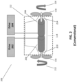
- FIG. 2 is a detailed illustration of a conventional propulsion arrangement 200 including the CRP pod propulsion system 112 of FIG. 1B , coupled to motor drives 202 and 204.
- Electric motors 206 and 208 are electrically coupled to the motor drives 202 and 204, respectively.
- the motor drives 202 and 204 provide control signals, in varying frequencies, to control the respective electric motor's speed, torque, etc.
- the drive 202 provides control signals to the electric motor 206.
- the electric motor 206 provides power, via a shaft 210, to drive the propeller 116 in a rotational direction 212.
- the drive 204 provides control signals to the electric motor 208.
- the electric motor 208 provides power, via a shaft 214, to drive the propeller 118 in a rotational direction 216.
- the drives 202 and 204 operate to independently control the corresponding motors 206 and 208.
- the drives 202 and 204 are configured to apply power separately. Consequently, the drives 202 and 204 drive the motors 206 and 208 completely independently and at different revolutions/minute (RPMs). If, for example, the drive 204 fails during operation, the functionality of both the drive 204 and the motor 208 will be lost.
- RPMs revolutions/minute
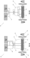
- FIG. 3A is an illustration of a smaller and lighter weight propulsion arrangement 300, constructed to provide redundancy in accordance with a first embodiment of the present disclosure.
- a CRP pod propulsion system (CRP Pod) 302 is electrically connected to motor drives 304 and 306.
- the motor drives 304 and 306 are configured for coupling to the CRP Pod 302 by way of a disconnector (i.e., switch) 308 and a slip-ring 310.
- a disconnector i.e., switch
- the slip-ring 310 provides a mechanical connection to permit rotation of the CRP Pod 302.
- the slip-ring 310 also permits transmission of electrical power, and other signals, between the stationary disconnector 308 and the CRP Pod 302.
- the CRP Pod 302 includes a strut 313 and electric motors 314 and 316.
- the strut 313 connects the electric motors 314 and 316 to the slip-ring 310, and ultimately to the hull of a marine vessel.
- the electric motors 314 and 316 are configured for coupling to the drives 304 and 306.
- a driving-end of the electrical motor 314 is connected to a propeller 318 via a shaft 317.
- the motor 314 produces thrust to rotate the propeller 318 in a rotational direction 320.
- a driving-end of the electrical motor 316 is connected to a propeller 322 via a shaft 324.
- the motor 316 produces thrust to rotate the propeller 322 in a rotational direction 328.
- the drives 304 and 306 are variable frequency drives that facilitate speed and direction control of the electric motors 314 and 316.
- the drives 304 and 306 and are interconnected to operate interdependently via the switch 308.
- the inter-dependent operation enables the drives 304 and 306 to keep the propellers 318 and 322 spinning at substantially the same RPM.
- the interdependency also provides redundancy.
- both of the drives 304 and 306 can simultaneously drive one, or both, of the motors 314 and 316. Conversely, each of the drives 304 and 306 can separately drive both of the motors 314 and 316. Accordingly, if either of the drives 304 and 306 is inoperable, the other drive can continue to control both motors 314 and 316 simultaneously. In some cases, the motors 314 and 316 can operate at a reduced level of power (e.g., a 50% reduction) when one of the drives 304 or 306 fails.
- a reduced level of power e.g., a 50% reduction
- the motors 314 and 316 can operate simultaneously at full power (e.g., if the drives 314 and 316 are oversized)
- one of the drives 304 or 306 can power both of the motors 314 and 316 at the same time.
- FIG. 3B is an illustration of a smaller and lighter weight propeller arrangement 330 constructed to provide redundancy in accordance with a second embodiment of the present disclosure.
- the propeller arrangement 330 is substantially equivalent to the propeller arrangement 300.
- the distinction is in the design of switches 331 and 332.
- the propeller arrangement 330 is an alternative approach for providing redundancy, based on the way the drives 304 and 306 are configured and/or how the switches 331 and 332 are used.
- a CRP Pod 333 is electrically connected to drives 304 and 306 of FIG. 3A .
- the electrical drives 304 and 306 are configured for electrical coupling to the CRP Pod 333 and to the motors 314 and 316 by way of the two switches 331 and 332, instead of the single switch 308 of FIG. 3A .
- one switch 332 is positioned internal to the CRP Pod 333 and another switch 331 is positioned externally. Using the switches 331 and 332, power can be provided to power only one of the motors 314 and 316 (separately). Alternatively, the switches 331 and 332 can provide power to both of the motors 314 and 316 (simultaneously).
- FIG. 4A is a detailed cross-sectional view of the CRP Pod 302 depicted in FIG. 3A .
- sections of the CRP Pod 302 e.g., propeller modules
- the motor 314 is encased within a gondola 402 formed of a compact watertight fuselage, or canister.
- a rotor of the electric motor 314 is detachably connected to a single bearing 403 and rotates about a shaft line 405 to drive the shaft 317.
- the shaft 317 is coupled to the propeller 318.
- FIG. 4B is a more detailed view of the single bearing 403 within the propeller module 404 depicted in FIG. 4A .
- the single slewing bearing 403 is the only bearing along the shaft line 405 and is capable of accommodating loads in five degrees of freedom.
- the single bearing 403 is capable of handling axial, radial, and lever arm loads.
- the single bearing 403 can be a slewing bearing 440, although the present disclosure is not so limited.
- conventional pod propulsion systems generally provide multiple bearings along the shaft line, which contribute to the length of the shaft line 405.
- the single bearing 403 is configured to accommodate axial, thrust, radial, and lever arm loads for compact arrangement, maximization of motor length for a given gondola length, and less auxiliaries and monitoring.
- the single bearing 403 handles thrust from the propeller 318, while also handling a radial load resulting from the weight of the propeller 318 on one side, and the weight of the motor 314 on the other side. Using the single bearing 403 provides for a more compact shaft line 405, further reducing the weight of the propeller module 404.
- an axial shaft locking system inside each propeller module 404 and 406, can be used to temporarily lock the shaft lines and for safe return to port (SRTP).
- a propeller module 406 includes the motor 316, encased within a gondola 408, and the propeller 322. Other components within the propeller module 406 are substantially identical to components described above in reference to the propeller module 404. Accordingly, the following descriptions describing the propeller module 404 also apply to the propeller module 406.
- the motor 314, within the propeller module 404, can be a canned motor for simplified industrialization, testing, reduced weight, and exchange of active parts.
- a canned motor is self-contained and packaged within a compact outer shell.
- canned motors can also be cooled by an independent flow of seawater.
- the propeller modules 404 and 406 integrate electric motors 314 and 316 (i.e., propulsion motors) that can be shrink fitted for thinner and smaller diameter gondolas 402 and 408. This approach is suitable for producing low torque density motors up to around 80 kilonewtons per cubic meter (kNm/m3).
- Active parts within the propeller modules 404 and 406 reduce their weight and helps reduce the size (and diameter) of the corresponding gondolas 402 and 408.
- the active parts provide for more compact construction, and eases manufacturing challenges. In this manner, the strut 313 can be manufactured separately from the gondolas 402 and 408.
- the strut 313 is connectable to the gondolas 402 and 408 through horizontally aligned boltable interfaces 410A and 410B along an extremity of each of the gondolas 402 and 404.
- the boltable interfaces 410A and 410B are horizontally aligned with (i.e., substantially parallel to) a lengthwise direction (A) of the propeller modules 404 and 406.
- FIG. 4A provides better air and cable access to the active parts inside the gondolas 402 and 408.
- FIGs. 5-7 provide detailed illustrations of sub-sections of the boltable interfaces 410A and 410B.
- FIG. 4C is a cross-sectional view of a CRP pod propulsion system 412 in an alternative embodiment that includes vertically aligned connectable interfaces.
- the CRP pod propulsion system 412 includes a strut 414 connectable to propeller modules 416 and 418.
- the propeller modules 416 and 418 include motor gondolas 420 and 422, respectively.
- the strut 414 includes a vertically oriented connecting section 424.
- the vertically oriented connecting section 424 is connectable to the gondolas 420 and in 422.
- the connection is formed through vertically aligned boltable interfaces 426 and 428 along extremities of each of the gondolas 420 and 422, respectively.
- boltable interfaces 426 and 428 are substantially orthogonal to a lengthwise direction (B) of the propeller modules 416 and 418 .
- the propulsion system 412 can circulate sea water for cooling to internal active parts a full 360 degrees around an outer shell, along circulation paths 430 and 432 outside the gondolas 420 and 422, respectively.
- FIG. 5 is an illustration of the strut 313 depicted in the CRP Pod 302 of FIGs. 3A and 4A . Also illustrated is a steering module 502 connectable to the strut 313 for rotating the strut 313 to steer the marine vessel. FIG. 5 also depicts a boltable interface 500 at a bottom extremity of the strut 313 to form a water-tight interface along a lengthwise direction of the gondolas 402 and 408. The steering module 502 is similarly configured for boltable interface to the strut 313.
- FIG. 6 is a detailed illustration of the gondolas 402 and 408 having respective boltable water-tight interfaces 600 and 602 positioned at extremities thereof.
- the water-tight connection between the boltable interfaces 500, 600, and 602 provide protection for maintenance workers as the gondolas 402 and 404 will be underwater during maintenance and testing.
- FIG. 7 is a detailed cross-sectional view of connections between the boltable interfaces 500 of the CRP Pod 302 and the boltable interfaces 600 and 602 of the gondolas 402 and 408 depicted in FIGs. 5-6 , respectively.
- a cutaway cross-sectional portion 700 of the strut 313 is shown, along with cutaway cross-sectional views 702 and 704 of the gondolas 402 and 408, respectively.
- the boltable interfaces 600 and 602 near the top of the gondolas 402 and 408, form a bolted water-tight connection with the boltable interface 500 at the bottom of the strut 313.
- the interface is secured via bolt type fasteners, although embodiments of the disclosure are not limited to bolts.
- the boltable interfaces enables the gondolas 402 and 408, the strut 313, and the steering module 502 provide enhanced industrialization.
- the gondolas 402 and 408, the strut 313, and the steering module 502 can be manufactured separately at reduced weights and can be tested using less complex test setups.
- the propellers 318 and 322 can be connected to the motors 314 and 316 and ultimately bolted to the strut 313. This reconnection will facilitate monitoring, for example, of the electrical connections of, and a supply of power to, the motors 314 and 316.
- pod propulsion systems will not require large test setups for lifting the complete CRP pod system. Instead, a smaller and less costly test setup can be used to test only the much lighter propeller modules 402 and 408and not the entire CRP pod 302.
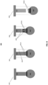
- FIG. 8 is an illustration of an exemplary process 800 for dislodging the propeller modules 404 and 406 from the strut 313 of the CRP pod 302.
- the dislodging process 800 permits underwater changing of the gondolas 402 and/or 408 while in dry in dock.
- the gondola 402 could be delivered for dry dock maintenance for quick and modular replacement.
- the dislodging process 800 provides a plug-and-play strategy that avoids changing the complete CRP pod 302 for most maintenance tasks. If one of the propeller modules 404 and 406 is damaged, for example, the damaged propeller module can be changed in the dry dock without dismounting the complete pod.
- the process 800 represents a method for underwater dislodging of the gondola 402 of the CRP pod 302 from the strut 313, disassembly and exchanging the strut 313.
- seals 801A are positioned within the strut 313 in a vicinity of bolted connections, formed from the boltable interfaces 410A and 410B, for inflation at a later time.
- the bolted connections are sealed and water-tighted as depicted at 802, to facilitate floating.
- An external lifting system 803 is provided by the maintenance worker for securing the gondola 402 during the dislodging process as depicted at 804 and to facilitate floating.
- the seals 801A are inflated to form inflated seals 801B that protect the maintenance worker.
- the fully inflated seals 801B provide the ability for a maintenance person to safely go inside the strut 313.
- bolts 805 can be removed, as depicted in 806.
- the bolts 805 are inside the CRP pod 302.
- the strut 313 can be pressurized to prevent water from entering.
- the gondola 402 is dislodged and lowered onto a dedicated cradle (not shown) or onto the seabed, as depicted in 808.
- a lid can be placed on the boltable interfaces 410A and 410B, making the propeller modules 404 and 406 watertight.
- a seal of the boltable interface 410A and 410B can be reinforced to facilitate releasing most of the bolts with maintenance personnel in the strut 313.
- a lifting arrangement can be attached to release most of the bolts holding the propeller modules 404 and 406 to a structure of the strut 313. Release of the final bolts can be performed remotely, permitting the lowering and removal of the propeller modules 404 and 406.
- both the module modules 404 and 406 and the strut 313 can be sealed at the interface (e.g., one cover plate for each).
- Watertight bolt connections can be used (in long tubes - or seals e.g., O-rings).
- An alternative pod propulsion system implementation includes providing a CRP solution in azimuth mechanical thruster. This arrangement, for example, can similarly produce a thinner pod. Another approach could include two independent propulsors or one propulsor behind a main propeller.
- Additional advantages include improved maintainability due to an ability to exchange propulsion modules with or without dry docks and because of smaller modules.
- the single bearing shaft line for each motor provides a very short and compact pod, reduces size and weight, and increases the hydrodynamic efficiency.
- the embodiments provide improved fuel cost savings on the magnitude of at least 7% (5% for contra rotative propeller, a slender gondola, and 2% for PM motors). Reduced maintenance costs are provided due to increased access in the pod, and independent propulsion modules. Also provided is a capability to change propulsion modules afloat, even for large pods, as a result of a dedicated interface for the propulsion module and the strut.
Landscapes
- Chemical & Material Sciences (AREA)
- Engineering & Computer Science (AREA)
- Combustion & Propulsion (AREA)
- Mechanical Engineering (AREA)
- Ocean & Marine Engineering (AREA)
- Connection Of Motors, Electrical Generators, Mechanical Devices, And The Like (AREA)
- Structures Of Non-Positive Displacement Pumps (AREA)
- Earth Drilling (AREA)
Abstract
Description
- The following relates generally to counter-rotating propeller (CRP) pod propulsion systems for marine vessels. More specifically, the following relates to arrangements and configuration of internal components of the pod propulsion system.
- Conventional marine vessel pod propulsion systems suffer shortcomings in several areas. For example, conventional pod propulsion systems tend to be heavier and larger than other propulsion system approaches given the size of the internal components. Also, the conventional pod propulsion systems' generally lack redundancy.
- Within various types of pod propulsion systems, CRP pods can offer improved efficiencies over single-screw (i.e., single propeller) pods. As understood by those of skill in the art, CRP pods include counter rotating propellers - one at each end of the pod. By way of background, some arrangements also provide two counter-rotating propellers at one end.
- CRP pods reduce the hydrodynamic flow rotational losses, after the propeller, of single-screw pod systems. CRP pods are also designed to include two electric motors along and with two corresponding motor drives that enable independent operation of the two motors. Conventional CRP pods, however, are generally penalized by weight and size as they require two independent shaft lines (i.e., two sets of bearings for each shaft). Also, the independent operation of conventional two-motor CRP pods generally fails to provide any significant redundancy, for example, in the event of a motor or drive failure.
- Given the aforementioned deficiencies, a need exists for a CRP pod propulsion system for a marine vessel that provides higher efficiencies than the existing CRP pods, offers reductions in size and weight, and provides redundant operation in the event of a critical failure in one of the electric motors, a corresponding motor drive, or similar.
- In certain circumstances, embodiments of the present disclosure provide a pod propulsion system including first and second counter rotating propellers for propelling a marine vessel, comprising: first and second propeller modules, each including an electric motor having a driving-end configured to rotate the first and second propellers, respectively; first and second gondolas, each (i) for housing a respective one of the first and second electric motors and (ii) including a boltable interface formed along a lengthwise direction of an extremity of the gondola; and a strut (i) for connecting the first and second gondolas to a hull of the marine vessel (ii) including first and second boltable interfaces. Each of the boltable interfaces of the strut is configured to form a bolted joint interface with a corresponding one of boltable interfaces of the first and second gondolas. The pod propulsion system may be a CRP pod propulsion system.
- The bolted joint interfaces may form a substantially horizontal or substantially vertical watertight seal between the strut and the first and second gondolas.
- The extremities of the first and second gondolas may be formed on a top surface thereof.
- Each of the first and second gondolas may include a watertight interface in a vicinity of their respective boltable interface.
- The first and second propellers may be dismounted from the respective first and second electric motors. The dismounting may facilitate independent testing of the first and second motors without their respective first and second propellers.
- In certain circumstances, embodiments of the present disclosure provide a counter rotating propeller pod (CRP) propulsion system including first and second counter rotating propellers for generating thrust to propel a marine vessel, comprising: first and second propeller modules, each including an electric motor having a driving-end (i) connectable to a propeller and (ii) configured to rotate the propeller about an axis of rotation, the axis of rotation forming a shaft line; and a single bearing (i) for connecting the driving-end to the propeller and (ii) configured to accommodate at least one of axial, radial and lever arm loads.
- Preferably, only the single bearing is positioned along the shaft line for accommodating the axial, radial and lever arm loads.
- Each of the electric motors may be canned within one propulsion module.
- Each of the propulsion modules may include a shaft brake system for locking the shaft line for safe return to port.
- Each of the propulsion modules may be sealed and exchangeable afloat.
- The single bearing may be capable of accommodating loads in five degrees of freedom.
- The single bearing may be a slewing bearing.
- The single bearing may be configured to provide a detachable connection between the motor and the propeller.
- In certain circumstances, embodiments of the present disclosure provide a method for dislodging portions of a CRP pod propulsion system under-water, the system including at least one motor gondola housing an electric motor and connected to a strut of a propeller module via bolts in a bolted interface seal, the method comprising: supplying one or more inflatable seals within the strut to reinforce the bolted interface seal; water-tighting the bolted interface seal; providing an external lifting system for securing the gondola during the dislodging; and removing the bolts under-water.
- Removing the bolts may include inflating the inflatable seals.
- The method may further comprise pressurizing the strut to dislodge the gondola from the strut.
- The bolts may be removed by maintenance personnel in dry dock.
- The pressurizing and dislodging may facilitate replacement of the dislodged gondola with another gondola.
- The CRP pod propulsion system is preferably attached to a marine vessel. The external lifting system may include lifting and guiding tooling rods affixed to a hull of the marine vessel.
- The embodiments are unique in combining CRP pod propulsion system hydrodynamics with two independent, dismountable, and compact propulsion modules fixed to a strut. These arrangements are lighter in weight, easier to manufacture, and easier to test. The lighter weight results from enhanced permanent magnet (PM) motor technology, other e-motors, and system construction. Also provided are reduced module outline dimensions, especially length, due to a single bearing arrangement on propulsion modules within the CRP pod propulsion system.
- Full redundancy of CRP pod systems results from independent, and interdependently operating, propulsion modules. Fully redundant operation is derived from two independent sets of active parts and powerline between the drive and motor arrangement. In the event of a failure of one propulsion module, the second propulsion module can remain 100% mechanically and electrically operable.
- In the event of a failure of one drive, both the propulsion modules can be operated simultaneously (up to 100% in some cases). Additionally, the embodiments spread the global power of the CRP pod propulsion system across two motors, ultimately enabling construction of motors and gondolas having smaller diameters and better CRP performance. There is also a unicity of power supplies per motor (e.g., one drive per motor, one drive for two motors).
- The embodiments are very efficient, improving CRP pod propulsion hydrodynamic performance by around 3-5%. The embodiments also provide improved industrialization by virtue of using more active, smaller, modularized, and dismountable components. The use of smaller and modularized components improves maintainability and reduces the reliance on intricate testing facilities since many of the modules can be tested individually.
- In one exemplary system, a single bearing along the shaft line of each motor results in a shorter and more compact motor module. The more compact modules are smaller, lighter, and increase hydrodynamic efficiency.
- These and other aspects of the present disclosure will become apparent from following description of the embodiments taken in conjunction with the following drawings and their captions, although variations and modification therein may be affected without departing from the spirit and scope of the novel concepts of the disclosure.
- Illustrative embodiments may take form in various components and arrangements of components. Illustrative embodiments are shown in the accompanying drawings, throughout which like reference numerals may indicate corresponding or similar parts in the various drawings. The drawings are only for purposes of illustrating the embodiments and are not to be construed as limiting the disclosure. Given the following enabling description of the drawings, the novel aspects of the present disclosure should become evident to a person of ordinary skill in the relevant art(s).
-
FIG. 1A is a high-level illustration of a conventional single-screw pod propulsion system in a marine vessel. -
FIG. 1B is a high-level illustration of a conventional CRP pod propulsion system in the marine vessel depicted inFIG. 1A . -
FIG. 2 is a detailed illustration of a conventional CRP pod propulsion system. -
FIGs. 3A and 3B are illustrations of CRP pod propulsion systems constructed in accordance with first and second embodiments of the present disclosure. -
FIG. 4A is a detailed cross-sectional view of the CRP pod propulsion system depicted inFIG. 3A . -
FIG. 4B is a more detailed view of the single bearing shaft line depicted inFIG. 4A . -
FIG. 4C is a more detailed cross-sectional view of the CRP pod propulsion system depicted inFIG. 4A . -
FIG. 5 is an illustration of a strut and steering module associated with the CRP pod propulsion system depicted inFIG. 4A . -
FIG. 6 is an illustration of the pod propulsion modules in the CRP pod propulsion system depicted inFIG. 4A . -
FIG. 7 is a detailed cross-sectional view of an exemplary bolted interface for a strut and at least one propeller module in accordance with the embodiments. -
FIG. 8 is an illustration of exemplary steps for dislodging a pod propulsion module from a strut in a CRP pod propulsion system in accordance with the embodiments. - While the illustrative embodiments are described herein for particular applications, it should be understood that the present disclosure is not limited thereto. Those skilled in the art and with access to the teachings provided herein will recognize additional applications, modifications, and embodiments within the scope thereof and additional fields in which the present disclosure would be of significant utility.
- The present disclosure describes embodiments of a CRP pod propulsion system for providing thrust to propel a marine vessel. One illustrative embodiment includes a 5-25 megawatt (MW) pod propulsion system with an internal arrangement providing maintainability for a range of pod components. An exemplary CRP pod system includes propulsion modules made with canned motors for simplified industrialization, testing, reduced weight, and an exchange of active parts. Each propulsion module includes an electric motor housed in a gondola. The gondola has a bolted interface and is configured for water-tight connection with a strut. The strut connects the gondola to the hull of the marine vessel.
- Obtaining maximum propulsion module efficiency is an important goal during module design. Maximum efficiency occurs as a result of trade-offs between at least three interrelated factors. Included among these factors are hydrodynamic efficiencies, motor solution efficiency, and pod auxiliary efficiencies. By way of example, auxiliary system may include (e.g., cooling systems, steering systems, and other supporting systems.
- In one exemplary embodiment, propulsion module efficiency is increased by providing gondolas with smaller diameters. The smaller diameter gondolas can translate to significantly higher CRP propulsion system hydrodynamics. By way of example, pod thrust is linked to motor torque, which depends on motor active parts volume. Motor manufacturing depends on maximum core length. By having two motors in the gondola, cumulated motor length is increased, thus reducing the motor diameter. The one exemplary embodiment also includes reduced strut widths and reduced wet surfaces.
- For PM motor with the same diameter and core length, efficiency is typically 2% above synchronous and asynchronous motor efficiencies due to reduced rotor losses. The pod auxiliary efficiency depends on consumption of lubrication, motor cooling etc. Motor technology, motor power density and motor cooling type influence hydrodynamic shape and hydrodynamic efficiency. The embodiments optimize the trade-offs between hydrodynamic performance, motor solutions, and auxiliary efficiencies.
- With large motors, it can be more difficult to absorb shocks. It is better to have smaller and lighter motors to deal with shock and vibration. Therefore, it is better to split the power across multiple motors (e.g., two motors) inside the gondola. Accordingly, the embodiments provide pods with the most compact active parts, as illustrated in
FIGs. 1A-8 , and the corresponding discussion below. -
FIG. 1A is a high-level illustration of a conventional single-screwpod propulsion system 100 for use in amarine vessel 102. The single-screwpod propulsion system 100 includes apropulsion module 104, including a motor (not shown). Asingle propeller 106 is attached to a shaft at a driving-end of the motor. Thepropulsion module 104 is coupled to astrut 108 for attaching thepropulsion system 100 to ahull 110 of themarine vessel 102. A significant deficiency of the conventional single-screwpod propulsion system 100 relates to the hydrodynamic flow of itssingle propeller 106. - Specifically, the hydrodynamic flow after the
single propeller 106 has a rotational component representing a loss to the thrust produced by thepropeller 106. A counter-rotating propeller, after the first propeller, is provided in CRP pod propulsion systems. The counter-rotating propeller reduces the rotational losses to near zero, improving the overall performance of the system. -
FIG. 1B is a high-level illustration of a conventional CRPpod propulsion system 112 affixed to themarine vessel 102. The CRPpod propulsion system 112 includes at least two electric motors (discussed in greater detail below). Apropeller 116 and a correspondingcounter-rotating propeller 118 are connected to respective shafts at driving-ends of the respective motors. - A
strut 120 section connects the motors and thepropellers hull 110 of theship 102. Thecounter-rotating propeller 118, rotating in one direction, substantially eliminates the rotational losses produced as thepropeller 116 rotates in an opposite direction. As a result, the CRPpod propulsion system 112 operates more efficiently than thepod propulsion system 100. However, the CRPpod propulsion system 112 suffers at least one critical shortcoming: it lacks redundancy. - The CRP
pod propulsion system 112 fails to offer any significant redundancy in the event of a critical component failure, such as the complete failure of an electric motor or a motor drive.FIG. 2 is a detailed illustration of aconventional propulsion arrangement 200 including the CRPpod propulsion system 112 ofFIG. 1B , coupled tomotor drives -
Electric motors FIG. 2 , thedrive 202 provides control signals to theelectric motor 206. Theelectric motor 206 provides power, via ashaft 210, to drive thepropeller 116 in arotational direction 212. Similarly, thedrive 204 provides control signals to theelectric motor 208. Theelectric motor 208 provides power, via ashaft 214, to drive thepropeller 118 in arotational direction 216. - In the
propulsion arrangement 200, thedrives motors drives drives motors drive 204 fails during operation, the functionality of both thedrive 204 and themotor 208 will be lost. -
FIG. 3A is an illustration of a smaller and lighterweight propulsion arrangement 300, constructed to provide redundancy in accordance with a first embodiment of the present disclosure. In thepropulsion arrangement 300, a CRP pod propulsion system (CRP Pod) 302 is electrically connected tomotor drives - The motor drives 304 and 306 are configured for coupling to the
CRP Pod 302 by way of a disconnector (i.e., switch) 308 and a slip-ring 310. As well understood by persons of skill in the art, the slip-ring 310 provides a mechanical connection to permit rotation of theCRP Pod 302. In the embodiments, the slip-ring 310 also permits transmission of electrical power, and other signals, between thestationary disconnector 308 and theCRP Pod 302. - The
CRP Pod 302 includes astrut 313 andelectric motors strut 313 connects theelectric motors ring 310, and ultimately to the hull of a marine vessel. Theelectric motors drives electrical motor 314 is connected to apropeller 318 via ashaft 317. Themotor 314 produces thrust to rotate thepropeller 318 in arotational direction 320. Similarly, a driving-end of theelectrical motor 316 is connected to apropeller 322 via ashaft 324. Themotor 316 produces thrust to rotate thepropeller 322 in arotational direction 328. - By way of example only, and not limitation, the
drives electric motors drives switch 308. The inter-dependent operation enables thedrives propellers - In one example of redundancy, both of the
drives motors drives motors drives motors motors drives motors drives drives motors -
FIG. 3B is an illustration of a smaller and lighterweight propeller arrangement 330 constructed to provide redundancy in accordance with a second embodiment of the present disclosure. Thepropeller arrangement 330 is substantially equivalent to thepropeller arrangement 300. The distinction is in the design ofswitches propeller arrangement 330 is an alternative approach for providing redundancy, based on the way thedrives switches propeller arrangement 330, aCRP Pod 333 is electrically connected todrives FIG. 3A . - In the
propeller arrangement 330, theelectrical drives CRP Pod 333 and to themotors switches single switch 308 ofFIG. 3A . InFIG. 3B , oneswitch 332 is positioned internal to theCRP Pod 333 and anotherswitch 331 is positioned externally. Using theswitches motors 314 and 316 (separately). Alternatively, theswitches motors 314 and 316 (simultaneously). -
FIG. 4A is a detailed cross-sectional view of theCRP Pod 302 depicted inFIG. 3A . In the embodiments, sections of the CRP Pod 302 (e.g., propeller modules) comprise similar active parts that provide modularity and correspondingly, a reduction in the pod's weight. As depicted inFIG. 4A , themotor 314 is encased within agondola 402 formed of a compact watertight fuselage, or canister. Within thegondola 402, a rotor of theelectric motor 314 is detachably connected to asingle bearing 403 and rotates about ashaft line 405 to drive theshaft 317. Theshaft 317 is coupled to thepropeller 318. -
FIG. 4B is a more detailed view of thesingle bearing 403 within thepropeller module 404 depicted inFIG. 4A . Thesingle slewing bearing 403 is the only bearing along theshaft line 405 and is capable of accommodating loads in five degrees of freedom. For example, thesingle bearing 403 is capable of handling axial, radial, and lever arm loads. In one exemplary embodiment, thesingle bearing 403 can be a slewingbearing 440, although the present disclosure is not so limited. - By way of background, conventional pod propulsion systems generally provide multiple bearings along the shaft line, which contribute to the length of the
shaft line 405. In theCRP Pod 302, thesingle bearing 403 is configured to accommodate axial, thrust, radial, and lever arm loads for compact arrangement, maximization of motor length for a given gondola length, and less auxiliaries and monitoring. - In one example, the
single bearing 403 handles thrust from thepropeller 318, while also handling a radial load resulting from the weight of thepropeller 318 on one side, and the weight of themotor 314 on the other side. Using thesingle bearing 403 provides for a morecompact shaft line 405, further reducing the weight of thepropeller module 404. - If problems develop with one of the
propeller modules propeller module - Returning to
FIG. 4A , themotor 314 and thepropeller 318 together form apropeller module 404. Apropeller module 406 includes themotor 316, encased within agondola 408, and thepropeller 322. Other components within thepropeller module 406 are substantially identical to components described above in reference to thepropeller module 404. Accordingly, the following descriptions describing thepropeller module 404 also apply to thepropeller module 406. - The
motor 314, within thepropeller module 404, can be a canned motor for simplified industrialization, testing, reduced weight, and exchange of active parts. As used herein, a canned motor is self-contained and packaged within a compact outer shell. By way of example only, and not limitation, canned motors can also be cooled by an independent flow of seawater. Thepropeller modules electric motors 314 and 316 (i.e., propulsion motors) that can be shrink fitted for thinner andsmaller diameter gondolas - Active parts within the
propeller modules gondolas strut 313 can be manufactured separately from thegondolas - For example, in the
CRP Pod 302 ofFIG. 4A , thestrut 313 is connectable to thegondolas boltable interfaces gondolas FIG. 4A , theboltable interfaces propeller modules - The horizontal alignment provides better air and cable access to the active parts inside the
gondolas FIG. 4A , other fastening mechanisms known to those of skill in the art would be suitable and within the scope of the present disclosure.FIGs. 5-7 provide detailed illustrations of sub-sections of theboltable interfaces -
FIG. 4C is a cross-sectional view of a CRPpod propulsion system 412 in an alternative embodiment that includes vertically aligned connectable interfaces. For example, the CRPpod propulsion system 412 includes astrut 414 connectable topropeller modules propeller modules motor gondolas strut 414 includes a vertically oriented connectingsection 424. The vertically oriented connectingsection 424 is connectable to thegondolas 420 and in 422. The connection is formed through vertically alignedboltable interfaces gondolas - In being vertically aligned,
boltable interfaces propeller modules propulsion system 412 can circulate sea water for cooling to internal active parts a full 360 degrees around an outer shell, alongcirculation paths gondolas -
FIG. 5 is an illustration of thestrut 313 depicted in theCRP Pod 302 ofFIGs. 3A and4A . Also illustrated is asteering module 502 connectable to thestrut 313 for rotating thestrut 313 to steer the marine vessel.FIG. 5 also depicts aboltable interface 500 at a bottom extremity of thestrut 313 to form a water-tight interface along a lengthwise direction of thegondolas steering module 502 is similarly configured for boltable interface to thestrut 313. -
FIG. 6 is a detailed illustration of thegondolas tight interfaces boltable interfaces gondolas -
FIG. 7 is a detailed cross-sectional view of connections between theboltable interfaces 500 of theCRP Pod 302 and theboltable interfaces gondolas FIGs. 5-6 , respectively. InFIG. 7 , a cutawaycross-sectional portion 700 of thestrut 313 is shown, along with cutawaycross-sectional views gondolas boltable interfaces gondolas boltable interface 500 at the bottom of thestrut 313. In the example ofFIG. 7 , the interface is secured via bolt type fasteners, although embodiments of the disclosure are not limited to bolts. - The boltable interfaces enables the
gondolas strut 313, and thesteering module 502 provide enhanced industrialization. For example, thegondolas strut 313, and thesteering module 502 can be manufactured separately at reduced weights and can be tested using less complex test setups. For example, during testing it is desirable to separate theelectric motors 314 and 316 (inside thegondolas 402 and 408) from the correspondingpropellers strut 313. This approach permits theelectric motors propellers - After testing, the
propellers motors strut 313. This reconnection will facilitate monitoring, for example, of the electrical connections of, and a supply of power to, themotors lighter propeller modules 402 and 408and not theentire CRP pod 302. -
FIG. 8 is an illustration of anexemplary process 800 for dislodging thepropeller modules strut 313 of theCRP pod 302. Thedislodging process 800 permits underwater changing of thegondolas 402 and/or 408 while in dry in dock. For example, thegondola 402 could be delivered for dry dock maintenance for quick and modular replacement. Thedislodging process 800 provides a plug-and-play strategy that avoids changing thecomplete CRP pod 302 for most maintenance tasks. If one of thepropeller modules - In one exemplary embodiment, the
process 800 represents a method for underwater dislodging of thegondola 402 of theCRP pod 302 from thestrut 313, disassembly and exchanging thestrut 313. Before commencement of theprocess 800,seals 801A are positioned within thestrut 313 in a vicinity of bolted connections, formed from theboltable interfaces external lifting system 803 is provided by the maintenance worker for securing thegondola 402 during the dislodging process as depicted at 804 and to facilitate floating. - The
seals 801A are inflated to forminflated seals 801B that protect the maintenance worker. The fullyinflated seals 801B provide the ability for a maintenance person to safely go inside thestrut 313. Afterwards,bolts 805 can be removed, as depicted in 806. Thebolts 805 are inside theCRP pod 302. After thebolts 805 are removed, thestrut 313 can be pressurized to prevent water from entering. Thegondola 402 is dislodged and lowered onto a dedicated cradle (not shown) or onto the seabed, as depicted in 808. - During an earlier preparation phase, preparatory steps are taken such as disconnecting cables and auxiliaries. A lid can be placed on the
boltable interfaces propeller modules boltable interface strut 313. A lifting arrangement can be attached to release most of the bolts holding thepropeller modules strut 313. Release of the final bolts can be performed remotely, permitting the lowering and removal of thepropeller modules - In one alternative to the
process 800, both themodule modules strut 313 can be sealed at the interface (e.g., one cover plate for each). Watertight bolt connections can be used (in long tubes - or seals e.g., O-rings). - An alternative pod propulsion system implementation includes providing a CRP solution in azimuth mechanical thruster. This arrangement, for example, can similarly produce a thinner pod. Another approach could include two independent propulsors or one propulsor behind a main propeller.
- Additional advantages include improved maintainability due to an ability to exchange propulsion modules with or without dry docks and because of smaller modules. The single bearing shaft line for each motor provides a very short and compact pod, reduces size and weight, and increases the hydrodynamic efficiency.
- The embodiments provide improved fuel cost savings on the magnitude of at least 7% (5% for contra rotative propeller, a slender gondola, and 2% for PM motors). Reduced maintenance costs are provided due to increased access in the pod, and independent propulsion modules. Also provided is a capability to change propulsion modules afloat, even for large pods, as a result of a dedicated interface for the propulsion module and the strut.
- The description herein is provided to enable a person skilled in the art to make or use the disclosure. Various modifications to the disclosure will be apparent to those skilled in the art, and the generic principles defined herein may be applied to other variations without departing from the scope of the disclosure. Thus, the disclosure is not limited to the examples and designs described herein but is to be accorded the broadest scope consistent with the principles and novel features disclosed herein.
Claims (18)
- A pod propulsion system (300) including first and second counter rotating propellers (318, 322) for propelling a marine vessel, the pod propulsion system (300) comprising:first and second propulsion modules (404, 406), each including an electric motor (314, 316) having a driving-end configured to rotate the first and second propellers (318, 322), respectively;first and second gondolas (402, 408), each configured to house a respective one of the first and second electric motors (314, 316) and including a boltable interface (600, 602) formed along a lengthwise direction of an extremity of the gondola (402, 408); anda strut (313) configured to connect the first and second gondolas (402, 408) to a hull of the marine vessel and including first and second boltable interfaces (500);wherein each of the boltable interfaces (500) of the strut (313) is configured to form a bolted j oint interface (410A, 410B; 426, 428) with a corresponding one of boltable interfaces (600, 602) of the first and second gondolas (402, 408).
- A pod propulsion system (300) according to claim 1, wherein the bolted joint interfaces (410A, 410B) form a substantially horizontal watertight seal between the strut (313) and the first and second gondolas (402, 408).
- A pod propulsion system (300) according to claim 1, wherein the bolted joint interfaces (426, 428) form a substantially vertical watertight seal between the strut (313) and the first and second gondolas (402, 408).
- A pod propulsion system (300) according to claim 1, wherein the extremities of the first and second gondolas (402, 408) are formed on a top surface thereof.
- A pod propulsion system (300) according to any preceding claim, wherein each of the first and second gondolas (402, 408) includes a watertight interface in a vicinity of their respective boltable interface.
- A pod propulsion system (300) according to any preceding claim, wherein the first and second propellers (318, 322) are configured to be dismountable from the respective first and second electric motors (314, 316), e.g., to facilitate independent testing of the first and second electric motors (314, 316) without their respective first and second propellers (318, 322).
- A counter rotating propeller CRP pod propulsion system (300) for generating thrust to propel a marine vessel, the pod propulsion system (300) comprising:
first and second propulsion modules (404, 406), each including:an electric motor (314, 316) having a driving-end connectable to a respective propeller (318, 322) and configured to rotate the propeller (318, 322) about an axis of rotation, the axis of rotation forming a shaft line; anda single bearing (403) for connecting the driving-end of the electric motor (314, 316) to the respective propeller (318, 322) and configured to accommodate at least one of axial, radial and lever arm loads. - A pod propulsion system (300) according to claim 7, wherein only the single bearing (403) is positioned along the shaft line for accommodating the axial, radial and lever arm loads.
- A pod propulsion system (300) according to claim 7 or claim 8, wherein each of the electric motors (314, 316) is canned within the respective propulsion module (404, 406).
- A pod propulsion system (300) according to claim 9, wherein each of the propulsion modules (404, 406) includes a shaft brake system for locking the shaft line for safe return to port.
- A pod propulsion system (300) according to any of claims 7 to 10, wherein each of the propulsion modules (404, 406) is configured to be sealable and exchangeable afloat.
- A pod propulsion system (300) according to any of claims 7 to 11, wherein each single bearing (403) is configured to accommodate loads in five degrees of freedom.
- A pod propulsion system (300) according to any of claims 7 to 12, wherein each single bearing (403) is a slewing bearing (440).
- A pod propulsion system according to any of claims 7 to 13, wherein each single bearing (403) is configured to provide a detachable connection between the electric motor (314, 316) and the respective propeller (318, 322).
- A method for dislodging portions of a pod propulsion system (300) under-water, the pod propulsion system (300) including at least one motor gondola (402) housing an electric motor (314) and connected to a strut (313) via bolts (805) in a bolted interface seal, the method comprising:supplying one or more inflatable seals (801A) within the strut (313) to reinforce the bolted interface seal;providing an external lifting system (803) for securing the gondola (402) during the dislodging; andremoving the bolts (805) under-water.
- A method according to claim 15, further comprising inflating the inflatable seals (801A) before removing the bolts.
- A method according to claim 15 or claim 16, further comprising pressurizing the strut (313) to dislodge the gondola (402) from the strut (313).
- A method according to any of claims 15 to 17, wherein the pod propulsion system (300) is attached to a marine vessel; and
wherein the external lifting system (803) includes lifting and guiding tooling rods affixed to a hull of the marine vessel.
Applications Claiming Priority (2)
| Application Number | Priority Date | Filing Date | Title |
|---|---|---|---|
| US202263302536P | 2022-01-24 | 2022-01-24 | |
| US17/715,000 US12365438B2 (en) | 2022-01-24 | 2022-04-06 | Counter rotating propeller pod mechanical arrangement |
Publications (3)
| Publication Number | Publication Date |
|---|---|
| EP4227204A2 true EP4227204A2 (en) | 2023-08-16 |
| EP4227204A3 EP4227204A3 (en) | 2023-10-18 |
| EP4227204B1 EP4227204B1 (en) | 2025-12-24 |
Family
ID=85076447
Family Applications (1)
| Application Number | Title | Priority Date | Filing Date |
|---|---|---|---|
| EP23153036.1A Active EP4227204B1 (en) | 2022-01-24 | 2023-01-24 | Counter rotating propeller pod mechanical arrangement |
Country Status (3)
| Country | Link |
|---|---|
| US (1) | US12365438B2 (en) |
| EP (1) | EP4227204B1 (en) |
| FI (1) | FI4227204T3 (en) |
Families Citing this family (3)
| Publication number | Priority date | Publication date | Assignee | Title |
|---|---|---|---|---|
| EP4280426A1 (en) | 2022-05-17 | 2023-11-22 | GE Energy Power Conversion Technology Ltd | Synchronous electrical machine, and associated propulsion oriented drive device, boat, and method for cooling such a machine |
| US12668328B1 (en) * | 2023-06-28 | 2026-06-30 | Brunswick Corporation | Hydrofoil apparatuses, systems, and methods for marine vessels |
| CN117622424B (en) * | 2023-11-30 | 2026-07-14 | 武汉船用电力推进装置研究所(中国船舶集团有限公司第七一二研究所) | Can maintain nacelle structure |
Citations (2)
| Publication number | Priority date | Publication date | Assignee | Title |
|---|---|---|---|---|
| US5947779A (en) * | 1996-08-16 | 1999-09-07 | Abb Azipod Oy | Propulsion device |
| US20030194922A1 (en) * | 2002-04-16 | 2003-10-16 | Pieter Van Dine | Rim-driven propulsion pod arrangement |
Family Cites Families (7)
| Publication number | Priority date | Publication date | Assignee | Title |
|---|---|---|---|---|
| US2691356A (en) * | 1950-11-28 | 1954-10-12 | Waterval William | Multiple propeller drive for ships |
| US3167361A (en) * | 1963-05-28 | 1965-01-26 | Ralph B Snapp | Rotating bearing |
| FR2788032B1 (en) * | 1998-12-30 | 2002-03-22 | Jeumont Ind | PROPULSION DEVICE FOR A NAVAL VESSEL |
| US7018249B2 (en) * | 2001-11-29 | 2006-03-28 | Siemens Aktiengesellschaft | Boat propulsion system |
| JP4217185B2 (en) * | 2004-03-29 | 2009-01-28 | 株式会社新来島どっく | Mounting method of pod propulsion device |
| KR101779735B1 (en) * | 2015-06-09 | 2017-09-18 | 바르트실라 네덜란드 비.브이. | A sealing arrangement for an underwater mountable thruster of a marine vessel |
| US10759511B2 (en) | 2018-06-26 | 2020-09-01 | Thrustmaster of Texas, Inc. | Floating vessel with gearless pod propulsor having counter rotating propellers |
-
2022
- 2022-04-06 US US17/715,000 patent/US12365438B2/en active Active
-
2023
- 2023-01-24 EP EP23153036.1A patent/EP4227204B1/en active Active
- 2023-01-24 FI FIEP23153036.1T patent/FI4227204T3/en active
Patent Citations (2)
| Publication number | Priority date | Publication date | Assignee | Title |
|---|---|---|---|---|
| US5947779A (en) * | 1996-08-16 | 1999-09-07 | Abb Azipod Oy | Propulsion device |
| US20030194922A1 (en) * | 2002-04-16 | 2003-10-16 | Pieter Van Dine | Rim-driven propulsion pod arrangement |
Also Published As
| Publication number | Publication date |
|---|---|
| US12365438B2 (en) | 2025-07-22 |
| US20230234691A1 (en) | 2023-07-27 |
| EP4227204A3 (en) | 2023-10-18 |
| EP4227204B1 (en) | 2025-12-24 |
| FI4227204T3 (en) | 2026-02-09 |
Similar Documents
| Publication | Publication Date | Title |
|---|---|---|
| EP4227204B1 (en) | Counter rotating propeller pod mechanical arrangement | |
| EP4215434B1 (en) | Counter rotating propeller pod electrical arrangement | |
| CA2107202C (en) | Ship propulsion arrangement | |
| US5078628A (en) | Marine propulsor | |
| US11121550B2 (en) | Power distribution system for a marine vessel | |
| AU2015306936A1 (en) | Carbon fiber motor rotor integrating propeller mount | |
| CN106240779A (en) | Pull-type full circle swinging electric power gondola propulsion system peculiar to vessel | |
| US20030054705A1 (en) | Device for reducing noise and absorbing vibrations generated by an electric motor integrated in a ship propulsion nacelle | |
| CN103347780A (en) | Components used to steer a ship and supply power to its propulsion system | |
| EP1050454A2 (en) | External electric drive propulsion module arrangement for SWATH vessels | |
| EP1488503B1 (en) | System and method for braking a motor of a propulsion unit | |
| AU5263899A (en) | Boat or vessel with electric drive | |
| US20240400178A1 (en) | Propulsors | |
| JP4221493B2 (en) | Counter-rotating propeller type pod type propulsion device for ships | |
| KR102937829B1 (en) | Structure of connecting portion for rotor sail | |
| KR100308180B1 (en) | Underwater Propulsion | |
| JP4217185B2 (en) | Mounting method of pod propulsion device | |
| US20250136261A1 (en) | Inboard marine motor drive and propulsion system | |
| CN105857542A (en) | High-speed and high-efficiency safety guarantee ship | |
| Holt et al. | High efficiency, counter-rotating ring thruster for underwater vehicles | |
| JP2024538083A (en) | Cyclorotor | |
| Rains et al. | Podded destroyer propulsion | |
| FI76977B (en) | Propeller drive arrangement for a ship or similar | |
| Shimamoto et al. | Tandem hybrid CRP (contra-rotating propeller) system | |
| CN120664096A (en) | Gearless propulsion device suitable for ice area ship |
Legal Events
| Date | Code | Title | Description |
|---|---|---|---|
| PUAI | Public reference made under article 153(3) epc to a published international application that has entered the european phase |
Free format text: ORIGINAL CODE: 0009012 |
|
| STAA | Information on the status of an ep patent application or granted ep patent |
Free format text: STATUS: THE APPLICATION HAS BEEN PUBLISHED |
|
| AK | Designated contracting states |
Kind code of ref document: A2 Designated state(s): AL AT BE BG CH CY CZ DE DK EE ES FI FR GB GR HR HU IE IS IT LI LT LU LV MC ME MK MT NL NO PL PT RO RS SE SI SK SM TR |
|
| PUAL | Search report despatched |
Free format text: ORIGINAL CODE: 0009013 |
|
| AK | Designated contracting states |
Kind code of ref document: A3 Designated state(s): AL AT BE BG CH CY CZ DE DK EE ES FI FR GB GR HR HU IE IS IT LI LT LU LV MC ME MK MT NL NO PL PT RO RS SE SI SK SM TR |
|
| RIC1 | Information provided on ipc code assigned before grant |
Ipc: B63B 81/00 20200101ALI20230914BHEP Ipc: B63B 17/00 20060101ALI20230914BHEP Ipc: B63H 5/10 20060101AFI20230914BHEP |
|
| RAP1 | Party data changed (applicant data changed or rights of an application transferred) |
Owner name: GE ENERGY POWER CONVERSION TECHNOLOGY LTD |
|
| STAA | Information on the status of an ep patent application or granted ep patent |
Free format text: STATUS: REQUEST FOR EXAMINATION WAS MADE |
|
| 17P | Request for examination filed |
Effective date: 20240412 |
|
| RBV | Designated contracting states (corrected) |
Designated state(s): AL AT BE BG CH CY CZ DE DK EE ES FI FR GB GR HR HU IE IS IT LI LT LU LV MC ME MK MT NL NO PL PT RO RS SE SI SK SM TR |
|
| GRAP | Despatch of communication of intention to grant a patent |
Free format text: ORIGINAL CODE: EPIDOSNIGR1 |
|
| STAA | Information on the status of an ep patent application or granted ep patent |
Free format text: STATUS: GRANT OF PATENT IS INTENDED |
|
| RIC1 | Information provided on ipc code assigned before grant |
Ipc: B63H 5/10 20060101AFI20250702BHEP Ipc: B63H 25/42 20060101ALI20250702BHEP Ipc: B63B 17/00 20060101ALI20250702BHEP Ipc: B63B 81/00 20200101ALI20250702BHEP Ipc: B63H 23/35 20060101ALI20250702BHEP Ipc: B63B 71/00 20200101ALI20250702BHEP Ipc: B63H 23/32 20060101ALI20250702BHEP Ipc: B63B 85/00 20200101ALI20250702BHEP Ipc: B63H 5/125 20060101ALI20250702BHEP Ipc: B63H 21/17 20060101ALI20250702BHEP Ipc: B63H 21/30 20060101ALI20250702BHEP Ipc: B63H 23/24 20060101ALI20250702BHEP |
|
| INTG | Intention to grant announced |
Effective date: 20250715 |
|
| GRAS | Grant fee paid |
Free format text: ORIGINAL CODE: EPIDOSNIGR3 |
|
| GRAA | (expected) grant |
Free format text: ORIGINAL CODE: 0009210 |
|
| STAA | Information on the status of an ep patent application or granted ep patent |
Free format text: STATUS: THE PATENT HAS BEEN GRANTED |
|
| AK | Designated contracting states |
Kind code of ref document: B1 Designated state(s): AL AT BE BG CH CY CZ DE DK EE ES FI FR GB GR HR HU IE IS IT LI LT LU LV MC ME MK MT NL NO PL PT RO RS SE SI SK SM TR |
|
| REG | Reference to a national code |
Ref country code: CH Ref legal event code: F10 Free format text: ST27 STATUS EVENT CODE: U-0-0-F10-F00 (AS PROVIDED BY THE NATIONAL OFFICE) Effective date: 20251224 Ref country code: GB Ref legal event code: FG4D |
|
| REG | Reference to a national code |
Ref country code: DE Ref legal event code: R096 Ref document number: 602023009940 Country of ref document: DE |
|
| REG | Reference to a national code |
Ref country code: FI Ref legal event code: FGE |
|
| REG | Reference to a national code |
Ref country code: LT Ref legal event code: MG9D |
|
| PG25 | Lapsed in a contracting state [announced via postgrant information from national office to epo] |
Ref country code: NO Free format text: LAPSE BECAUSE OF FAILURE TO SUBMIT A TRANSLATION OF THE DESCRIPTION OR TO PAY THE FEE WITHIN THE PRESCRIBED TIME-LIMIT Effective date: 20260324 |
|
| PGFP | Annual fee paid to national office [announced via postgrant information from national office to epo] |
Ref country code: DE Payment date: 20260121 Year of fee payment: 4 |
|
| PG25 | Lapsed in a contracting state [announced via postgrant information from national office to epo] |
Ref country code: HR Free format text: LAPSE BECAUSE OF FAILURE TO SUBMIT A TRANSLATION OF THE DESCRIPTION OR TO PAY THE FEE WITHIN THE PRESCRIBED TIME-LIMIT Effective date: 20251224 |
|
| PGFP | Annual fee paid to national office [announced via postgrant information from national office to epo] |
Ref country code: AT Payment date: 20260301 Year of fee payment: 4 |
|
| PGFP | Annual fee paid to national office [announced via postgrant information from national office to epo] |
Ref country code: FI Payment date: 20260121 Year of fee payment: 4 Ref country code: IT Payment date: 20260131 Year of fee payment: 4 |
|
| PG25 | Lapsed in a contracting state [announced via postgrant information from national office to epo] |
Ref country code: RS Free format text: LAPSE BECAUSE OF FAILURE TO SUBMIT A TRANSLATION OF THE DESCRIPTION OR TO PAY THE FEE WITHIN THE PRESCRIBED TIME-LIMIT Effective date: 20260324 |
|
| PGFP | Annual fee paid to national office [announced via postgrant information from national office to epo] |
Ref country code: FR Payment date: 20260121 Year of fee payment: 4 |
|
| PG25 | Lapsed in a contracting state [announced via postgrant information from national office to epo] |
Ref country code: LV Free format text: LAPSE BECAUSE OF FAILURE TO SUBMIT A TRANSLATION OF THE DESCRIPTION OR TO PAY THE FEE WITHIN THE PRESCRIBED TIME-LIMIT Effective date: 20251224 |
|
| REG | Reference to a national code |
Ref country code: NL Ref legal event code: MP Effective date: 20251224 |
|
| PG25 | Lapsed in a contracting state [announced via postgrant information from national office to epo] |
Ref country code: BG Free format text: LAPSE BECAUSE OF FAILURE TO SUBMIT A TRANSLATION OF THE DESCRIPTION OR TO PAY THE FEE WITHIN THE PRESCRIBED TIME-LIMIT Effective date: 20251224 |
|
| PG25 | Lapsed in a contracting state [announced via postgrant information from national office to epo] |
Ref country code: NL Free format text: LAPSE BECAUSE OF FAILURE TO SUBMIT A TRANSLATION OF THE DESCRIPTION OR TO PAY THE FEE WITHIN THE PRESCRIBED TIME-LIMIT Effective date: 20251224 |
|
| PG25 | Lapsed in a contracting state [announced via postgrant information from national office to epo] |
Ref country code: LT Free format text: LAPSE BECAUSE OF FAILURE TO SUBMIT A TRANSLATION OF THE DESCRIPTION OR TO PAY THE FEE WITHIN THE PRESCRIBED TIME-LIMIT Effective date: 20251224 |
|
| PG25 | Lapsed in a contracting state [announced via postgrant information from national office to epo] |
Ref country code: SM Free format text: LAPSE BECAUSE OF FAILURE TO SUBMIT A TRANSLATION OF THE DESCRIPTION OR TO PAY THE FEE WITHIN THE PRESCRIBED TIME-LIMIT Effective date: 20251224 |
|
| PG25 | Lapsed in a contracting state [announced via postgrant information from national office to epo] |
Ref country code: ES Free format text: LAPSE BECAUSE OF FAILURE TO SUBMIT A TRANSLATION OF THE DESCRIPTION OR TO PAY THE FEE WITHIN THE PRESCRIBED TIME-LIMIT Effective date: 20251224 |
|
| PG25 | Lapsed in a contracting state [announced via postgrant information from national office to epo] |
Ref country code: PL Free format text: LAPSE BECAUSE OF FAILURE TO SUBMIT A TRANSLATION OF THE DESCRIPTION OR TO PAY THE FEE WITHIN THE PRESCRIBED TIME-LIMIT Effective date: 20251224 |
|
| PG25 | Lapsed in a contracting state [announced via postgrant information from national office to epo] |
Ref country code: EE Free format text: LAPSE BECAUSE OF FAILURE TO SUBMIT A TRANSLATION OF THE DESCRIPTION OR TO PAY THE FEE WITHIN THE PRESCRIBED TIME-LIMIT Effective date: 20251224 |
|
| PG25 | Lapsed in a contracting state [announced via postgrant information from national office to epo] |
Ref country code: IS Free format text: LAPSE BECAUSE OF FAILURE TO SUBMIT A TRANSLATION OF THE DESCRIPTION OR TO PAY THE FEE WITHIN THE PRESCRIBED TIME-LIMIT Effective date: 20260424 Ref country code: PT Free format text: LAPSE BECAUSE OF FAILURE TO SUBMIT A TRANSLATION OF THE DESCRIPTION OR TO PAY THE FEE WITHIN THE PRESCRIBED TIME-LIMIT Effective date: 20260424 |
|
| PG25 | Lapsed in a contracting state [announced via postgrant information from national office to epo] |
Ref country code: CZ Free format text: LAPSE BECAUSE OF FAILURE TO SUBMIT A TRANSLATION OF THE DESCRIPTION OR TO PAY THE FEE WITHIN THE PRESCRIBED TIME-LIMIT Effective date: 20251224 |
|
| PG25 | Lapsed in a contracting state [announced via postgrant information from national office to epo] |
Ref country code: SK Free format text: LAPSE BECAUSE OF FAILURE TO SUBMIT A TRANSLATION OF THE DESCRIPTION OR TO PAY THE FEE WITHIN THE PRESCRIBED TIME-LIMIT Effective date: 20251224 |
|
| PG25 | Lapsed in a contracting state [announced via postgrant information from national office to epo] |
Ref country code: SE Free format text: LAPSE BECAUSE OF FAILURE TO SUBMIT A TRANSLATION OF THE DESCRIPTION OR TO PAY THE FEE WITHIN THE PRESCRIBED TIME-LIMIT Effective date: 20251224 |