EP4227166A1 - Car provided with front pillar covering elements - Google Patents
Car provided with front pillar covering elements Download PDFInfo
- Publication number
- EP4227166A1 EP4227166A1 EP23155720.8A EP23155720A EP4227166A1 EP 4227166 A1 EP4227166 A1 EP 4227166A1 EP 23155720 A EP23155720 A EP 23155720A EP 4227166 A1 EP4227166 A1 EP 4227166A1
- Authority
- EP
- European Patent Office
- Prior art keywords
- car
- windshield
- front pillar
- covering element
- outer cover
- Prior art date
- Legal status (The legal status is an assumption and is not a legal conclusion. Google has not performed a legal analysis and makes no representation as to the accuracy of the status listed.)
- Granted
Links
Images




Classifications
-
- B—PERFORMING OPERATIONS; TRANSPORTING
- B60—VEHICLES IN GENERAL
- B60R—VEHICLES, VEHICLE FITTINGS, OR VEHICLE PARTS, NOT OTHERWISE PROVIDED FOR
- B60R13/00—Elements for body-finishing, identifying, or decorating; Arrangements or adaptations for advertising purposes
- B60R13/04—External Ornamental or guard strips; Ornamental inscriptive devices thereon
-
- B—PERFORMING OPERATIONS; TRANSPORTING
- B62—LAND VEHICLES FOR TRAVELLING OTHERWISE THAN ON RAILS
- B62D—MOTOR VEHICLES; TRAILERS
- B62D25/00—Superstructure or monocoque structure sub-units; Parts or details thereof not otherwise provided for
- B62D25/04—Door pillars ; windshield pillars
Definitions
- This invention relates to a car provided with front pillar covering elements.
- a car comprises a body covering a passenger compartment that is arranged between the front wheels and the rear wheels and is provided with (at least) two seats each designed to receive a corresponding occupant; the body comprises, among other things, a front bumper, a front hood, a windshield delimiting the passenger compartment at the front, a roof covering the passenger compartment above, a rear window delimiting the passenger compartment at the back, a rear hood, and a rear bumper.
- the body On the side, has two sides that are provided with at least two corresponding doors, each of which is equipped with a corresponding window that can be opened.
- the body also comprises two front pillars, each of which delimits the windshield to the side, originates from the waistline (i.e., from the upper outer limit of the closed area from which the glass surfaces extend up high), and ends in the roof.
- the two front pillars In almost all cars, the two front pillars have the same colour as the rest of the body (or at least as part of the rest of the body in the case of two-coloured bodies) .
- a different colour for example opaque black instead of shiny black
- each front pillar separates the windshield from a corresponding side window.
- the most widely known solution is to double paint the body to apply to the front pillars a different paint to the rest of the body; in any case, this solution is particularly costly especially when the production volumes are significant (and, thus, the painting operation is highly automated).
- the purpose of this invention is to provide a car provided with front pillar covering elements and without the drawbacks described above.
- the reference number 1 indicates, as a whole, a car comprising a frame, which supports a pair of driven front wheels 2 (i.e., not driving) and a pair of driving rear wheels 3. In a central position, there is an internal combustion engine, which produces torque that is transmitted to the rear driving wheels 3 via a transmission.
- the frame is covered by a body 4 that covers a passenger compartment, which is arranged between the front wheels 2 and the rear wheels 3 and is provided with (at least) two seats each designed to receive a corresponding occupant; i.e., in the passenger compartment, there is always a driver to whom you may add (at least) one passenger (whose presence is, obviously, optional).
- the body 4 comprises, among other things, a front bumper, a front hood 5 (covering a front luggage compartment), a windshield 6 delimiting the passenger compartment at the front, a roof 7 covering the passenger compartment above, a rear window 8 delimiting the passenger compartment at the back, a rear hood 9 (covering a rear engine compartment), and a rear bumper.
- the body 4 On the side, the body 4 has two sides that are provided with corresponding doors 10, each of which is equipped with a corresponding window 11 that can be opened.
- the body also 4 comprises two front pillars 12, each of which delimits the windshield 6 to the side, originates from the waistline (i.e., from the upper outer limit of the closed area from which the glass surfaces extend up high), and ends in the roof 7.
- the body 4 comprises a rear spoiler 13 that constitutes a seamless extension of the roof 7 towards the rear of the car; i.e., the rear spoiler 13 is arranged behind the roof 7 and is seamlessly connected to the roof 7 (i.e., without appreciable steps or empty spaces).
- the front pillars 12 have the function of supporting (containing) the windshield 6 to the side and supporting the roof 7 at the front, while the rear pillars 14 have the function of supporting (containing) the rear window 8 to the side and supporting the roof 7 at the rear.
- the roof 7 has four support points: two support points defined by the front pillars 12 and two support points defined by the rear pillars 14.
- the two front pillars 12 may directly support the roof 7 (or may be directly connected to the roof 7) or may indirectly support the roof 7 (or may end in a horizontal crossbar on which the roof 7 rests).
- the car 1 comprises two covering elements 15 of the front pillars 12; i.e., each covering element 15 covers and hides from the outside the corresponding front pillar 12 so that the front pillar 12 cannot be seen from the outside.
- each covering element 15 covers a corresponding front pillar 12 on the outside, comprises an outer cover 16 visible from the outside of the car 1, and comprises a support structure 17, which is glued to the outer cover 16 and is firmly attached to the corresponding front pillar 12.
- each covering element 15 only the support structure 17 is directly fixed to the corresponding front pillar 12 while the covering element 15 is glued to the support structure 17.
- each covering element 15 comprises multiple eyelets 18 (in particular, four eyelets 18), each of which is engaged by a screw 19 (illustrated in Figure 9 ), which is integral to the corresponding front pillar 12.
- each screw 19 engages a corresponding nut to lock the corresponding front pillar 12; alternatively, the nut is attached (welded) to the corresponding front pillar 12, or the corresponding front pillar 12 has a threaded hole that is engaged by the screw 19.
- calibrated compensation shims with variable dimensions may be inserted that make it possible to compensate for construction tolerances and, therefore, make it possible to confer the desired position to the outer cover 16.
- each covering element 15 comprises three inserts 20 (preferably with the shape of a parallelepiped), each of which is glued to the outer cover 16 next to the support structure 17 and consists of an elastically compressible plastic material.
- the inserts 20 are compressed and elastically deformed between the outer cover 16 and the corresponding front pillar 12 to seal any openings existing between the outer cover 16 and the corresponding front pillar 12; i.e., the inserts 20 are "filling" inserts that can be adapted that seal any openings between the outer cover 16 and the corresponding front pillar 12.
- the presence of the inserts 20 makes it possible to insulate the front pillar 12 (thus, the passenger compartment) from infiltrations of air and humidity and from the passage of external noise.
- each covering element 15 has a series of projections 21 (teeth) that are arranged below an edge of the windshield 6; in particular, the outer cover 16 of each covering element 15 has three projections 21 arranged at a certain distance from each other. In other words, through the projections 21 each covering element 15 is slotted on one side below an edge of the windshield 6.
- Figure 9 illustrates a cross section made outside the projections 21 (that cannot be seen in Figure 9 ) while Figure 10 illustrates a cross section made at one projection 21 (that is, thus, visible in Figure 10 ).
- a gasket 22 of the windshield 6 and an adhesive 23 that glues the windshield 6 to the corresponding front pillar 12 are also visible.
- seal 22 which is closed in a ring on itself and completely surrounds the windshield 6 on all sides.
- the adhesive 23 that is placed between the windshield 6 and each front pillar 12 and is arranged more inside the gasket 22, i.e., is arranged on the opposite side of the covering element 15 compared to the gasket 22.
- a gasket 22 is provided that is placed between the windshield 6 and each front pillar 12 and is shaped so as to create a space configured to receive the projections 21 of the corresponding outer cover 16.
- the gasket 22 has, in cross section, an "L" shape having a short side that connects the windshield 6 to each front pillar 12 and a long side that faces the outside of the windshield 6, is perpendicular to the short side, and delimits the space configured to receive the projections 21 of the corresponding outer cover 16.
- each gasket 24 is mounted (slotted) on a corresponding front pillar 12 and engages a corresponding side window 11.
- each gasket 24 is fixed (slotted) to the support structure 17 as well of a corresponding covering element 15.
- each front pillar 12 is box-shaped (or empty inside) and consists of two sheets 24 and 25 joined together (typically via welding).
- each covering element 15 is made of a moulded plastic material (and externally painted with the desired colour) while the support structure 17 of each covering element 15 is made of a metal material (alternatively, the support structure 17 of each covering element 15 could also be made of a moulded plastic material).
- the car 1 described above makes it possible to have a colour of the front pillars 12 different to that of the rest of the body 4.
- the car 1 described above makes it possible to obtain a different colour of the front pillars 12 in a simple and cost-effective way (especially without requiring the body 4 to be painted twice) while managing to have an excellent aesthetic result (in certain ways better than what can be obtained by the paint applied to the metal body).
- the covering elements 15 of the car 1 described above ensure a firm mounting (i.e., without weaknesses) and very precise (thanks to the possibility of also using compensation shims that make it possible to compensate for construction tolerances).
- the covering elements 15 of the car 1 described above also ensure excellent hydraulic, pneumatic, and acoustic insulation towards the passenger compartment thanks to the presence of the elastically compressible inserts 20 glued to the outer cover 16.
Landscapes
- Engineering & Computer Science (AREA)
- Mechanical Engineering (AREA)
- Chemical & Material Sciences (AREA)
- Combustion & Propulsion (AREA)
- Transportation (AREA)
- Body Structure For Vehicles (AREA)
Abstract
Description
- This patent application claims priority from
Italian patent application no. 102022000002387 filed on February 10, 2022 - This invention relates to a car provided with front pillar covering elements.
- A car comprises a body covering a passenger compartment that is arranged between the front wheels and the rear wheels and is provided with (at least) two seats each designed to receive a corresponding occupant; the body comprises, among other things, a front bumper, a front hood, a windshield delimiting the passenger compartment at the front, a roof covering the passenger compartment above, a rear window delimiting the passenger compartment at the back, a rear hood, and a rear bumper. On the side, the body has two sides that are provided with at least two corresponding doors, each of which is equipped with a corresponding window that can be opened. The body also comprises two front pillars, each of which delimits the windshield to the side, originates from the waistline (i.e., from the upper outer limit of the closed area from which the glass surfaces extend up high), and ends in the roof.
- In almost all cars, the two front pillars have the same colour as the rest of the body (or at least as part of the rest of the body in the case of two-coloured bodies) . For aesthetic reasons, it has been necessary to have just the two front pillars of a different colour (for example opaque black instead of shiny black) from the rest of the body so as to "disappear" (i.e., to be less noticed) in the middle of glass surfaces (in fact, each front pillar separates the windshield from a corresponding side window).
- To obtain the two front pillars with a different colour to the rest of the body, the most widely known solution is to double paint the body to apply to the front pillars a different paint to the rest of the body; in any case, this solution is particularly costly especially when the production volumes are significant (and, thus, the painting operation is highly automated).
- To obtain the two front pillars with a different colour from the rest of the body, it was proposed to cover the front pillars with a coloured adhesive film; in any case, this solution, though highly advantageous economically, obtains an acceptable aesthetic result, but not an excellent one.
- The patent applications
WO2020022020A1 ,JP2017217979A GB2566302A - The purpose of this invention is to provide a car provided with front pillar covering elements and without the drawbacks described above.
- According to this invention, a car provided with front pillar covering elements, according to that set forth in the appended claims, is provided.
- The claims describe preferred embodiments of this invention forming an integral part of this description.
- This invention will now be described with reference to the attached drawings that illustrate a non-limiting embodiment thereof:
-
Figure 1 is a front perspective view of a car produced according to this invention; -
Figure 2 is a rear perspective view of the car inFigure 1 ; -
Figure 3 is a plan view of the car inFigure 1 ; -
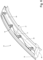
Figures 4 and5 are two different perspective views of the outside of a front pillar covering element of the car inFigure 1 ; -
Figure 6 is a perspective view from the inside of the covering element inFigures 4 and5 ; -
Figure 7 is a perspective view of a support structure of the covering element inFigures 4 and5 ; -
Figure 8 is a cross-section view of the covering element inFigures 4 and5 ; and -
Figures 9 and10 are two different cross-section views of the covering element ofFigures 4 and5 mounted on the car inFigure 1 . - In
Figure 1 , the reference number 1 indicates, as a whole, a car comprising a frame, which supports a pair of driven front wheels 2 (i.e., not driving) and a pair of drivingrear wheels 3. In a central position, there is an internal combustion engine, which produces torque that is transmitted to therear driving wheels 3 via a transmission. - The frame is covered by a
body 4 that covers a passenger compartment, which is arranged between thefront wheels 2 and therear wheels 3 and is provided with (at least) two seats each designed to receive a corresponding occupant; i.e., in the passenger compartment, there is always a driver to whom you may add (at least) one passenger (whose presence is, obviously, optional). - The
body 4 comprises, among other things, a front bumper, a front hood 5 (covering a front luggage compartment), awindshield 6 delimiting the passenger compartment at the front, aroof 7 covering the passenger compartment above, arear window 8 delimiting the passenger compartment at the back, a rear hood 9 (covering a rear engine compartment), and a rear bumper. On the side, thebody 4 has two sides that are provided withcorresponding doors 10, each of which is equipped with acorresponding window 11 that can be opened. The body also 4 comprises twofront pillars 12, each of which delimits thewindshield 6 to the side, originates from the waistline (i.e., from the upper outer limit of the closed area from which the glass surfaces extend up high), and ends in theroof 7. - According to what is better illustrated in
Figures 2 and3 , thebody 4 comprises arear spoiler 13 that constitutes a seamless extension of theroof 7 towards the rear of the car; i.e., therear spoiler 13 is arranged behind theroof 7 and is seamlessly connected to the roof 7 (i.e., without appreciable steps or empty spaces). - The
front pillars 12 have the function of supporting (containing) thewindshield 6 to the side and supporting theroof 7 at the front, while therear pillars 14 have the function of supporting (containing) therear window 8 to the side and supporting theroof 7 at the rear. In other words, theroof 7 has four support points: two support points defined by thefront pillars 12 and two support points defined by therear pillars 14. The twofront pillars 12 may directly support the roof 7 (or may be directly connected to the roof 7) or may indirectly support the roof 7 (or may end in a horizontal crossbar on which theroof 7 rests). - According to what is illustrated in
Figures 1 ,2 , and3 , the car 1 comprises two coveringelements 15 of thefront pillars 12; i.e., each coveringelement 15 covers and hides from the outside the correspondingfront pillar 12 so that thefront pillar 12 cannot be seen from the outside. - According to what is illustrated in
Figures 4-8 , each coveringelement 15 covers a correspondingfront pillar 12 on the outside, comprises anouter cover 16 visible from the outside of the car 1, and comprises asupport structure 17, which is glued to theouter cover 16 and is firmly attached to the correspondingfront pillar 12. In other words, in eachcovering element 15, only thesupport structure 17 is directly fixed to the correspondingfront pillar 12 while thecovering element 15 is glued to thesupport structure 17. - According to what is illustrated in
Figures 6 and7 , thesupport structure 17 of each coveringelement 15 comprises multiple eyelets 18 (in particular, four eyelets 18), each of which is engaged by a screw 19 (illustrated inFigure 9 ), which is integral to the correspondingfront pillar 12. According to a preferred embodiment, eachscrew 19 engages a corresponding nut to lock the correspondingfront pillar 12; alternatively, the nut is attached (welded) to the correspondingfront pillar 12, or the correspondingfront pillar 12 has a threaded hole that is engaged by thescrew 19. According to a preferred embodiment, at eachscrew 19 calibrated compensation shims with variable dimensions may be inserted that make it possible to compensate for construction tolerances and, therefore, make it possible to confer the desired position to theouter cover 16. - According to a preferred embodiment illustrated in
Figures 6-10 , each coveringelement 15 comprises three inserts 20 (preferably with the shape of a parallelepiped), each of which is glued to theouter cover 16 next to thesupport structure 17 and consists of an elastically compressible plastic material. In eachcovering element 15, theinserts 20 are compressed and elastically deformed between theouter cover 16 and thecorresponding front pillar 12 to seal any openings existing between theouter cover 16 and the correspondingfront pillar 12; i.e., theinserts 20 are "filling" inserts that can be adapted that seal any openings between theouter cover 16 and the correspondingfront pillar 12. In this way, the presence of theinserts 20 makes it possible to insulate the front pillar 12 (thus, the passenger compartment) from infiltrations of air and humidity and from the passage of external noise. - The
outer cover 16 of each coveringelement 15 has a series of projections 21 (teeth) that are arranged below an edge of thewindshield 6; in particular, theouter cover 16 of each coveringelement 15 has threeprojections 21 arranged at a certain distance from each other. In other words, through theprojections 21 each coveringelement 15 is slotted on one side below an edge of thewindshield 6.Figure 9 illustrates a cross section made outside the projections 21 (that cannot be seen inFigure 9 ) whileFigure 10 illustrates a cross section made at one projection 21 (that is, thus, visible inFigure 10 ). In particular, inFigures 9 and10 , agasket 22 of thewindshield 6 and an adhesive 23 that glues thewindshield 6 to the correspondingfront pillar 12 are also visible. There is oneseal 22, which is closed in a ring on itself and completely surrounds thewindshield 6 on all sides. Theadhesive 23 that is placed between thewindshield 6 and eachfront pillar 12 and is arranged more inside thegasket 22, i.e., is arranged on the opposite side of the coveringelement 15 compared to thegasket 22. - In other words, a
gasket 22 is provided that is placed between thewindshield 6 and eachfront pillar 12 and is shaped so as to create a space configured to receive theprojections 21 of the correspondingouter cover 16. In particular, thegasket 22 has, in cross section, an "L" shape having a short side that connects thewindshield 6 to eachfront pillar 12 and a long side that faces the outside of thewindshield 6, is perpendicular to the short side, and delimits the space configured to receive theprojections 21 of the correspondingouter cover 16. - The presence of the
projections 21 that, projecting from theouter covers 16 of the coveringelements 15 are slotted below thewindshield 6, makes it possible both to ensure a firm mounting (i.e., without weaknesses) of the coveringelements 15, and to disassemble (when necessary) the coveringelements 15 in a relatively simple and quick way without running the risk of undesired breakages or chipping of components. - According to what is illustrated in
Figures 9 and10 , a pair ofgaskets 24 is provided, each of which is mounted (slotted) on a correspondingfront pillar 12 and engages acorresponding side window 11. According to a preferred embodiment, eachgasket 24 is fixed (slotted) to thesupport structure 17 as well of acorresponding covering element 15. - According to what is illustrated in
Figures 9 and10 , eachfront pillar 12 is box-shaped (or empty inside) and consists of twosheets - According to a preferred embodiment, the
outer cover 16 of each coveringelement 15 is made of a moulded plastic material (and externally painted with the desired colour) while thesupport structure 17 of eachcovering element 15 is made of a metal material (alternatively, thesupport structure 17 of eachcovering element 15 could also be made of a moulded plastic material). - The embodiments described herein may be combined between them without departing from the scope of protection of this innovation.
- Numerous advantages are achieved with the car 1 described above.
- In the first place, the car 1 described above makes it possible to have a colour of the
front pillars 12 different to that of the rest of thebody 4. - In addition, the car 1 described above makes it possible to obtain a different colour of the
front pillars 12 in a simple and cost-effective way (especially without requiring thebody 4 to be painted twice) while managing to have an excellent aesthetic result (in certain ways better than what can be obtained by the paint applied to the metal body). - The covering
elements 15 of the car 1 described above ensure a firm mounting (i.e., without weaknesses) and very precise (thanks to the possibility of also using compensation shims that make it possible to compensate for construction tolerances). - The covering
elements 15 of the car 1 described above also ensure excellent hydraulic, pneumatic, and acoustic insulation towards the passenger compartment thanks to the presence of the elasticallycompressible inserts 20 glued to theouter cover 16. -
- 1
- car
- 2
- front wheels
- 3
- rear wheels
- 4
- body
- 5
- front hood
- 6
- windshield
- 7
- roof
- 8
- rear window
- 9
- rear hood
- 10
- doors
- 11
- window
- 12
- front pillars
- 13
- rear spoiler
- 14
- rear pillars
- 15
- covering elements
- 16
- outer cover
- 17
- support structure
- 18
- eyelets
- 19
- screw
- 20
- insert
- 21
- projections
- 22
- gasket
- 23
- adhesive
- 24
- sheet
- 25
- sheet
Claims (15)
- A car (1) comprising:two front wheels (2);two rear wheels (3);a passenger compartment arranged between the front wheels (2) and the rear wheels (3);a body (4) comprising: a windshield (6) delimiting the passenger compartment at the front, a roof (7) covering the passenger compartment at the top, and two front pillars (12), each delimiting the windshield (6) on the sides; andtwo covering elements (15), each of which covers a corresponding front pillar (12) on the outside, comprises an outer cover (16) visible from the outside of the car (1) and comprises a support structure (17), which is glued to the outer cover (16) and is firmly constrained to the corresponding front pillar (12);the car (1) is characterised in that the outer cover (16) of each covering element (15) has a series of projections (21) that are arranged below an edge of the windshield (6) and are arranged at a given distance from each other.
- The car (1) according to claim 1, wherein the support structure (17) of each covering element (15) comprises a plurality of eyelets (18), each engaged by a screw (19), which is integral to the corresponding front pillar (12).
- The car (1) according to claim 2, wherein each screw (19) engages a corresponding nut to lock the corresponding front pillar (12).
- The car (1) according to claim 1, 2 or 3, wherein each covering element (15) comprises at least one insert (20), which is glued to the outer cover (16) beside the support structure (17) and is made of an elastically compressible plastic material.
- The car (1) according to claim 4, wherein, in each covering element (15), the insert (20) has the shape of a parallelepiped.
- The car (1) according to claim 4 or 5, wherein, in each covering element (15), the insert (20) is elastically compressed and deformed between the outer cover (16) and the corresponding front pillar (12) in order to seal possible openings.
- The car (1) according to one of the claims from 1 to 6, wherein the outer cover (16) of each covering element (15) has three projections (21) that are arranged below the edge of the windshield (6).
- The car (1) according to one of the claims from 1 to 7, wherein through the projections (21) each covering element (15) is slotted in one side below the edge of the windshield (6) .
- The car (1) according to one of the claims from 1 to 8 and comprising a first gasket (22) that is placed between the windshield (6) and each front pillar (12) and is shaped to create a space configured to receive the projections (21) of the corresponding outer cover (16).
- The car (1) according to claim 9, wherein the first gasket (22) has, in cross section, an "L" shape having a short side that connects the windshield (6) to each front pillar (12) and a long side that is perpendicular to the short side, faces the outside of the windshield (6) and delimits the space configured to receive the projections (21) of the corresponding outer cover (16).
- The car according to claim 9 or 10, wherein the first seal (22) is single, is closed in a ring on itself and completely surrounds the windshield (6) on all sides.
- The car (1) according to claim 9, 10, or 11 and comprising an adhesive (23) that is placed between the windshield (6) and each front pillar (12) and is arranged more inside the first gasket (22), i.e., is arranged on the opposite side of the covering element (15) compared to the first gasket (22).
- The car (1) according to one of the claims from 1 to 12 and comprising a pair of second gaskets (24), each of which is mounted on a corresponding front pillar (12) and engages a corresponding side window (11).
- The car (1) according to claim 13, wherein each second gasket (24) is also fixed to the support structure (17) of a corresponding covering element (15).
- The car (1) according to one of the claims from 1 to 14, wherein:the outer cover (16) of each covering element (15) is made of a moulded plastic material; andthe support structure (17) of each covering element (15) is made of a metal material.
Applications Claiming Priority (1)
| Application Number | Priority Date | Filing Date | Title |
|---|---|---|---|
| IT102022000002387A IT202200002387A1 (en) | 2022-02-10 | 2022-02-10 | CAR EQUIPPED WITH COVERING ELEMENTS FOR THE FRONT pillars |
Publications (2)
| Publication Number | Publication Date |
|---|---|
| EP4227166A1 true EP4227166A1 (en) | 2023-08-16 |
| EP4227166B1 EP4227166B1 (en) | 2024-11-06 |
Family
ID=81384725
Family Applications (1)
| Application Number | Title | Priority Date | Filing Date |
|---|---|---|---|
| EP23155720.8A Active EP4227166B1 (en) | 2022-02-10 | 2023-02-09 | Car provided with front pillar covering elements |
Country Status (3)
| Country | Link |
|---|---|
| US (1) | US12552328B2 (en) |
| EP (1) | EP4227166B1 (en) |
| IT (1) | IT202200002387A1 (en) |
Families Citing this family (13)
| Publication number | Priority date | Publication date | Assignee | Title |
|---|---|---|---|---|
| CL2022001755S1 (en) * | 2021-12-28 | 2022-09-30 | Car | |
| JP1784478S (en) * | 2022-06-21 | 2024-11-13 | car | |
| USD1021720S1 (en) * | 2022-06-28 | 2024-04-09 | Ford Global Technologies, Llc | Vehicle fender |
| USD1042272S1 (en) * | 2022-09-07 | 2024-09-17 | GM Global Technology Operations LLC | Vehicle fender |
| USD1019497S1 (en) * | 2022-09-12 | 2024-03-26 | GM Global Technology Operations LLC | Vehicle fender |
| USD1050992S1 (en) * | 2022-10-17 | 2024-11-12 | Dr. Ing. H.C. F. Porsche Aktiengesellschaft | Fender for vehicle |
| USD1075604S1 (en) * | 2023-02-06 | 2025-05-20 | Hyundai Motor Company | Fender panel for automobiles |
| USD1048974S1 (en) * | 2023-03-10 | 2024-10-29 | GM Global Technology Operations LLC | Vehicle fender |
| USD1050991S1 (en) * | 2023-03-10 | 2024-11-12 | GM Global Technology Operations LLC | Vehicle fender |
| USD1103046S1 (en) | 2023-04-28 | 2025-11-25 | Aston Martin Lagonda Limited | Diffuser assembly for automobile or replica thereof |
| USD1120810S1 (en) * | 2023-04-28 | 2026-03-31 | Aston Martin Lagonda Limited | Automobile or replica thereof |
| USD1102959S1 (en) * | 2023-06-20 | 2025-11-25 | Ferrari S.P.A. | Car, toy car replica and/or other replica |
| USD1108310S1 (en) * | 2023-10-25 | 2026-01-06 | Nunzio La Vecchia | Automobile |
Citations (7)
| Publication number | Priority date | Publication date | Assignee | Title |
|---|---|---|---|---|
| EP1325827A1 (en) * | 2001-12-18 | 2003-07-09 | Accra Teknik AB | A-pillar and roof side section housing a seal for vehicle of sash-less door type |
| WO2005102781A1 (en) * | 2004-04-20 | 2005-11-03 | Daimlerchrysler Ag | Panel for covering a support element of a motor vehicle |
| DE202017103747U1 (en) * | 2017-06-23 | 2017-08-09 | WKW Erbslöh Automotive GmbH | pillar cover |
| JP2017217979A (en) | 2016-06-06 | 2017-12-14 | 本田技研工業株式会社 | Automobile front pillar structure |
| DE102016218676A1 (en) * | 2016-09-28 | 2018-03-29 | Bayerische Motoren Werke Aktiengesellschaft | motor vehicle |
| GB2566302A (en) | 2017-09-08 | 2019-03-13 | Jaguar Land Rover Ltd | A finisher assembly for a vehicle |
| WO2020022020A1 (en) | 2018-07-25 | 2020-01-30 | 本田技研工業株式会社 | Pillar outer garnish attachment structure |
Family Cites Families (2)
| Publication number | Priority date | Publication date | Assignee | Title |
|---|---|---|---|---|
| JP5685566B2 (en) * | 2012-09-27 | 2015-03-18 | 富士重工業株式会社 | Vehicle pillar structure |
| JP2018069785A (en) * | 2016-10-25 | 2018-05-10 | トヨタ車体株式会社 | Vehicular cabin front part structure |
-
2022
- 2022-02-10 IT IT102022000002387A patent/IT202200002387A1/en unknown
-
2023
- 2023-01-25 US US18/159,563 patent/US12552328B2/en active Active
- 2023-02-09 EP EP23155720.8A patent/EP4227166B1/en active Active
Patent Citations (7)
| Publication number | Priority date | Publication date | Assignee | Title |
|---|---|---|---|---|
| EP1325827A1 (en) * | 2001-12-18 | 2003-07-09 | Accra Teknik AB | A-pillar and roof side section housing a seal for vehicle of sash-less door type |
| WO2005102781A1 (en) * | 2004-04-20 | 2005-11-03 | Daimlerchrysler Ag | Panel for covering a support element of a motor vehicle |
| JP2017217979A (en) | 2016-06-06 | 2017-12-14 | 本田技研工業株式会社 | Automobile front pillar structure |
| DE102016218676A1 (en) * | 2016-09-28 | 2018-03-29 | Bayerische Motoren Werke Aktiengesellschaft | motor vehicle |
| DE202017103747U1 (en) * | 2017-06-23 | 2017-08-09 | WKW Erbslöh Automotive GmbH | pillar cover |
| GB2566302A (en) | 2017-09-08 | 2019-03-13 | Jaguar Land Rover Ltd | A finisher assembly for a vehicle |
| WO2020022020A1 (en) | 2018-07-25 | 2020-01-30 | 本田技研工業株式会社 | Pillar outer garnish attachment structure |
Also Published As
| Publication number | Publication date |
|---|---|
| US12552328B2 (en) | 2026-02-17 |
| EP4227166B1 (en) | 2024-11-06 |
| IT202200002387A1 (en) | 2023-08-10 |
| US20230249751A1 (en) | 2023-08-10 |
Similar Documents
| Publication | Publication Date | Title |
|---|---|---|
| EP4227166B1 (en) | Car provided with front pillar covering elements | |
| US4978164A (en) | Modular vehicle body structure | |
| EP1621384B1 (en) | Rear vehicle door | |
| US20190337575A1 (en) | Body structure for a battery-operated motor vehicle | |
| DE102008038647B4 (en) | Vehicle surface component with a solar cell arrangement | |
| EP1325862A2 (en) | Modular vehicle roof | |
| KR20120088877A (en) | Improved vehicle seal system, and/or method of making the same | |
| US7086693B1 (en) | Glass roof assembly and method of retrofitting a vehicle | |
| US20070182217A1 (en) | Transparent vehicle roof | |
| US10363970B2 (en) | Vehicle pillar structure | |
| US20180126832A1 (en) | Vehicle with moonroof and panoramic glass | |
| WO2021142414A1 (en) | Multi-panel removable roof system | |
| US20030047963A1 (en) | Hatchback for an automobile | |
| US10864806B2 (en) | Door for vehicle | |
| KR20200101569A (en) | Door for vehicle | |
| CN1332822C (en) | Sliding window for vehicle | |
| US20170253278A1 (en) | Motor vehicle body | |
| EP2799265B1 (en) | Door frame module for a modularly structured motor vehicle door and modularly structured motor vehicle door comprising such a door frame module | |
| RU2668022C1 (en) | Structural roof and vehicle supplied with the similar structural roofs | |
| US20060152043A1 (en) | Plastics material elongate member forming part of a roof structure, a roof structure member, a roof arch, a roof frame, and a roof module for a motor vehicle | |
| US10160501B1 (en) | Roof panel reinforcement | |
| AU9191698A (en) | Device for vehicles and method for manufacturing the device | |
| CN118046967B (en) | Passenger cabin structure with explosion-proof floor assembly and vehicle | |
| EP0378359A1 (en) | Glass mounting system | |
| EP1960253B1 (en) | Hatch frame for vehicle |
Legal Events
| Date | Code | Title | Description |
|---|---|---|---|
| PUAI | Public reference made under article 153(3) epc to a published international application that has entered the european phase |
Free format text: ORIGINAL CODE: 0009012 |
|
| STAA | Information on the status of an ep patent application or granted ep patent |
Free format text: STATUS: THE APPLICATION HAS BEEN PUBLISHED |
|
| AK | Designated contracting states |
Kind code of ref document: A1 Designated state(s): AL AT BE BG CH CY CZ DE DK EE ES FI FR GB GR HR HU IE IS IT LI LT LU LV MC ME MK MT NL NO PL PT RO RS SE SI SK SM TR |
|
| STAA | Information on the status of an ep patent application or granted ep patent |
Free format text: STATUS: REQUEST FOR EXAMINATION WAS MADE |
|
| 17P | Request for examination filed |
Effective date: 20231107 |
|
| RBV | Designated contracting states (corrected) |
Designated state(s): AL AT BE BG CH CY CZ DE DK EE ES FI FR GB GR HR HU IE IS IT LI LT LU LV MC ME MK MT NL NO PL PT RO RS SE SI SK SM TR |
|
| GRAP | Despatch of communication of intention to grant a patent |
Free format text: ORIGINAL CODE: EPIDOSNIGR1 |
|
| STAA | Information on the status of an ep patent application or granted ep patent |
Free format text: STATUS: GRANT OF PATENT IS INTENDED |
|
| INTG | Intention to grant announced |
Effective date: 20240605 |
|
| GRAS | Grant fee paid |
Free format text: ORIGINAL CODE: EPIDOSNIGR3 |
|
| GRAA | (expected) grant |
Free format text: ORIGINAL CODE: 0009210 |
|
| STAA | Information on the status of an ep patent application or granted ep patent |
Free format text: STATUS: THE PATENT HAS BEEN GRANTED |
|
| AK | Designated contracting states |
Kind code of ref document: B1 Designated state(s): AL AT BE BG CH CY CZ DE DK EE ES FI FR GB GR HR HU IE IS IT LI LT LU LV MC ME MK MT NL NO PL PT RO RS SE SI SK SM TR |
|
| REG | Reference to a national code |
Ref country code: GB Ref legal event code: FG4D |
|
| REG | Reference to a national code |
Ref country code: CH Ref legal event code: EP |
|
| REG | Reference to a national code |
Ref country code: DE Ref legal event code: R096 Ref document number: 602023000898 Country of ref document: DE |
|
| REG | Reference to a national code |
Ref country code: IE Ref legal event code: FG4D |
|
| REG | Reference to a national code |
Ref country code: LT Ref legal event code: MG9D |
|
| REG | Reference to a national code |
Ref country code: NL Ref legal event code: MP Effective date: 20241106 |
|
| PG25 | Lapsed in a contracting state [announced via postgrant information from national office to epo] |
Ref country code: HR Free format text: LAPSE BECAUSE OF FAILURE TO SUBMIT A TRANSLATION OF THE DESCRIPTION OR TO PAY THE FEE WITHIN THE PRESCRIBED TIME-LIMIT Effective date: 20241106 Ref country code: IS Free format text: LAPSE BECAUSE OF FAILURE TO SUBMIT A TRANSLATION OF THE DESCRIPTION OR TO PAY THE FEE WITHIN THE PRESCRIBED TIME-LIMIT Effective date: 20250306 Ref country code: PT Free format text: LAPSE BECAUSE OF FAILURE TO SUBMIT A TRANSLATION OF THE DESCRIPTION OR TO PAY THE FEE WITHIN THE PRESCRIBED TIME-LIMIT Effective date: 20250306 |
|
| PG25 | Lapsed in a contracting state [announced via postgrant information from national office to epo] |
Ref country code: FI Free format text: LAPSE BECAUSE OF FAILURE TO SUBMIT A TRANSLATION OF THE DESCRIPTION OR TO PAY THE FEE WITHIN THE PRESCRIBED TIME-LIMIT Effective date: 20241106 Ref country code: NL Free format text: LAPSE BECAUSE OF FAILURE TO SUBMIT A TRANSLATION OF THE DESCRIPTION OR TO PAY THE FEE WITHIN THE PRESCRIBED TIME-LIMIT Effective date: 20241106 |
|
| REG | Reference to a national code |
Ref country code: AT Ref legal event code: MK05 Ref document number: 1739045 Country of ref document: AT Kind code of ref document: T Effective date: 20241106 |
|
| PG25 | Lapsed in a contracting state [announced via postgrant information from national office to epo] |
Ref country code: BG Free format text: LAPSE BECAUSE OF FAILURE TO SUBMIT A TRANSLATION OF THE DESCRIPTION OR TO PAY THE FEE WITHIN THE PRESCRIBED TIME-LIMIT Effective date: 20241106 |
|
| PG25 | Lapsed in a contracting state [announced via postgrant information from national office to epo] |
Ref country code: ES Free format text: LAPSE BECAUSE OF FAILURE TO SUBMIT A TRANSLATION OF THE DESCRIPTION OR TO PAY THE FEE WITHIN THE PRESCRIBED TIME-LIMIT Effective date: 20241106 |
|
| PG25 | Lapsed in a contracting state [announced via postgrant information from national office to epo] |
Ref country code: NO Free format text: LAPSE BECAUSE OF FAILURE TO SUBMIT A TRANSLATION OF THE DESCRIPTION OR TO PAY THE FEE WITHIN THE PRESCRIBED TIME-LIMIT Effective date: 20250206 |
|
| PG25 | Lapsed in a contracting state [announced via postgrant information from national office to epo] |
Ref country code: AT Free format text: LAPSE BECAUSE OF FAILURE TO SUBMIT A TRANSLATION OF THE DESCRIPTION OR TO PAY THE FEE WITHIN THE PRESCRIBED TIME-LIMIT Effective date: 20241106 Ref country code: LV Free format text: LAPSE BECAUSE OF FAILURE TO SUBMIT A TRANSLATION OF THE DESCRIPTION OR TO PAY THE FEE WITHIN THE PRESCRIBED TIME-LIMIT Effective date: 20241106 Ref country code: GR Free format text: LAPSE BECAUSE OF FAILURE TO SUBMIT A TRANSLATION OF THE DESCRIPTION OR TO PAY THE FEE WITHIN THE PRESCRIBED TIME-LIMIT Effective date: 20250207 |
|
| PG25 | Lapsed in a contracting state [announced via postgrant information from national office to epo] |
Ref country code: PL Free format text: LAPSE BECAUSE OF FAILURE TO SUBMIT A TRANSLATION OF THE DESCRIPTION OR TO PAY THE FEE WITHIN THE PRESCRIBED TIME-LIMIT Effective date: 20241106 |
|
| PG25 | Lapsed in a contracting state [announced via postgrant information from national office to epo] |
Ref country code: RS Free format text: LAPSE BECAUSE OF FAILURE TO SUBMIT A TRANSLATION OF THE DESCRIPTION OR TO PAY THE FEE WITHIN THE PRESCRIBED TIME-LIMIT Effective date: 20250206 |
|
| PG25 | Lapsed in a contracting state [announced via postgrant information from national office to epo] |
Ref country code: SM Free format text: LAPSE BECAUSE OF FAILURE TO SUBMIT A TRANSLATION OF THE DESCRIPTION OR TO PAY THE FEE WITHIN THE PRESCRIBED TIME-LIMIT Effective date: 20241106 |
|
| PG25 | Lapsed in a contracting state [announced via postgrant information from national office to epo] |
Ref country code: DK Free format text: LAPSE BECAUSE OF FAILURE TO SUBMIT A TRANSLATION OF THE DESCRIPTION OR TO PAY THE FEE WITHIN THE PRESCRIBED TIME-LIMIT Effective date: 20241106 |
|
| PG25 | Lapsed in a contracting state [announced via postgrant information from national office to epo] |
Ref country code: EE Free format text: LAPSE BECAUSE OF FAILURE TO SUBMIT A TRANSLATION OF THE DESCRIPTION OR TO PAY THE FEE WITHIN THE PRESCRIBED TIME-LIMIT Effective date: 20241106 |
|
| PG25 | Lapsed in a contracting state [announced via postgrant information from national office to epo] |
Ref country code: RO Free format text: LAPSE BECAUSE OF FAILURE TO SUBMIT A TRANSLATION OF THE DESCRIPTION OR TO PAY THE FEE WITHIN THE PRESCRIBED TIME-LIMIT Effective date: 20241106 |
|
| PG25 | Lapsed in a contracting state [announced via postgrant information from national office to epo] |
Ref country code: SK Free format text: LAPSE BECAUSE OF FAILURE TO SUBMIT A TRANSLATION OF THE DESCRIPTION OR TO PAY THE FEE WITHIN THE PRESCRIBED TIME-LIMIT Effective date: 20241106 |
|
| PG25 | Lapsed in a contracting state [announced via postgrant information from national office to epo] |
Ref country code: CZ Free format text: LAPSE BECAUSE OF FAILURE TO SUBMIT A TRANSLATION OF THE DESCRIPTION OR TO PAY THE FEE WITHIN THE PRESCRIBED TIME-LIMIT Effective date: 20241106 |
|
| REG | Reference to a national code |
Ref country code: DE Ref legal event code: R097 Ref document number: 602023000898 Country of ref document: DE |
|
| PG25 | Lapsed in a contracting state [announced via postgrant information from national office to epo] |
Ref country code: SE Free format text: LAPSE BECAUSE OF FAILURE TO SUBMIT A TRANSLATION OF THE DESCRIPTION OR TO PAY THE FEE WITHIN THE PRESCRIBED TIME-LIMIT Effective date: 20241106 |
|
| PLBE | No opposition filed within time limit |
Free format text: ORIGINAL CODE: 0009261 |
|
| STAA | Information on the status of an ep patent application or granted ep patent |
Free format text: STATUS: NO OPPOSITION FILED WITHIN TIME LIMIT |
|
| PG25 | Lapsed in a contracting state [announced via postgrant information from national office to epo] |
Ref country code: MC Free format text: LAPSE BECAUSE OF FAILURE TO SUBMIT A TRANSLATION OF THE DESCRIPTION OR TO PAY THE FEE WITHIN THE PRESCRIBED TIME-LIMIT Effective date: 20241106 |
|
| 26N | No opposition filed |
Effective date: 20250807 |
|
| PG25 | Lapsed in a contracting state [announced via postgrant information from national office to epo] |
Ref country code: LU Free format text: LAPSE BECAUSE OF NON-PAYMENT OF DUE FEES Effective date: 20250209 |
|
| REG | Reference to a national code |
Ref country code: BE Ref legal event code: MM Effective date: 20250228 |
|
| PG25 | Lapsed in a contracting state [announced via postgrant information from national office to epo] |
Ref country code: BE Free format text: LAPSE BECAUSE OF NON-PAYMENT OF DUE FEES Effective date: 20250228 |
|
| PG25 | Lapsed in a contracting state [announced via postgrant information from national office to epo] |
Ref country code: IE Free format text: LAPSE BECAUSE OF NON-PAYMENT OF DUE FEES Effective date: 20250209 |
|
| PGFP | Annual fee paid to national office [announced via postgrant information from national office to epo] |
Ref country code: DE Payment date: 20260220 Year of fee payment: 4 |
|
| PGFP | Annual fee paid to national office [announced via postgrant information from national office to epo] |
Ref country code: IT Payment date: 20260228 Year of fee payment: 4 |
|
| PGFP | Annual fee paid to national office [announced via postgrant information from national office to epo] |
Ref country code: FR Payment date: 20260227 Year of fee payment: 4 |