EP4227164A1 - A vehicle camera arrangement, a vehicle camera module and a vehicle camera mounting bracket - Google Patents
A vehicle camera arrangement, a vehicle camera module and a vehicle camera mounting bracket Download PDFInfo
- Publication number
- EP4227164A1 EP4227164A1 EP22156797.7A EP22156797A EP4227164A1 EP 4227164 A1 EP4227164 A1 EP 4227164A1 EP 22156797 A EP22156797 A EP 22156797A EP 4227164 A1 EP4227164 A1 EP 4227164A1
- Authority
- EP
- European Patent Office
- Prior art keywords
- vehicle camera
- holding
- camera module
- mounting bracket
- hook
- Prior art date
- Legal status (The legal status is an assumption and is not a legal conclusion. Google has not performed a legal analysis and makes no representation as to the accuracy of the status listed.)
- Granted
Links
Images


Classifications
-
- B—PERFORMING OPERATIONS; TRANSPORTING
- B60—VEHICLES IN GENERAL
- B60R—VEHICLES, VEHICLE FITTINGS, OR VEHICLE PARTS, NOT OTHERWISE PROVIDED FOR
- B60R11/00—Arrangements for holding or mounting articles, not otherwise provided for
- B60R11/04—Mounting of cameras operative during drive; Arrangement of controls thereof relative to the vehicle
-
- B—PERFORMING OPERATIONS; TRANSPORTING
- B60—VEHICLES IN GENERAL
- B60R—VEHICLES, VEHICLE FITTINGS, OR VEHICLE PARTS, NOT OTHERWISE PROVIDED FOR
- B60R11/00—Arrangements for holding or mounting articles, not otherwise provided for
- B60R2011/0001—Arrangements for holding or mounting articles, not otherwise provided for characterised by position
- B60R2011/0003—Arrangements for holding or mounting articles, not otherwise provided for characterised by position inside the vehicle
- B60R2011/0026—Windows, e.g. windscreen
Definitions
- the present disclosure relates to a vehicle camera module and a vehicle camera mounting bracket, and to a vehicle camera arrangement comprising the vehicle camera module and the vehicle camera mounting bracket.
- vehicle environment detection systems comprise one or more sensors such as for example radar sensor, LIDAR sensors, ultrasonic sensors and digital camera devices. These are used for collecting data used for safety arrangements as well as for driver assistance systems.
- a camera device is adapted to collect images of the surroundings, and may be used to identify landmarks.
- a camera module is mounted to a camera mounting bracket that in turn is mounted to a vehicle.
- the camera module comprises a housing, a lens assembly and a PCB to which an image sensor and associated components are mounted.
- a vehicle camera module that comprises a housing with a rear portion and a front portion that is adapted to face a vehicle windscreen, and a lens assembly that at least partly is accommodated in the housing.
- the lens assembly extends along a first extension and comprises a lens aperture that is closer to the front portion than to the rear portion.
- the housing comprises a first holding section and a second holding section which holding sections protrude away from the first extension.
- the housing further comprises at least one holding rail extending between the rear portion and the front portion.
- the housing to be attached to another item, such as a camera mounting bracket.
- a secure attachment is enabled, where the holding sections and said at least one holding rail can be integrated into the housing.
- the holding sections extend along a second extension that runs perpendicular to a vertical plane running along the first extension.
- the holding sections are arranged along a line which will enable an uncomplicated mounting to another item, such as a camera mounting bracket.
- each holding section comprises a corresponding inner part and outer part.
- Each inner part is closer to the vertical plane than the corresponding outer part.
- each inner part has a largest cross-section area that falls below a largest cross-section area of the corresponding outer part in a corresponding plane perpendicular to the second extension.
- the outer parts will provide locking along the second extension.
- the housing further comprises at least one guiding rail that extends between the rear portion and the front portion. In this way, an increased stability is provided.
- a vehicle camera mounting bracket comprising a main plate with a longitudinal extension, a first main side that is adapted to be attached to a windscreen, and a second main side, opposite the first main side.
- the mounting bracket comprises a first holding arrangement and a second holding arrangement, the holding arrangements mainly extending parallel to the longitudinal extension and extending from the second main side.
- Each holding arrangement comprises a first hook-shaped receiving portion and a second hook-shaped receiving portion.
- the receiving portions are adapted to receive and releasably retain holding parts of a vehicle camera module.
- the vehicle camera mounting bracket further comprises at least one resilient member that extends from the second main side.
- each holding arrangement comprises a corresponding guiding portion that is adapted to guide guiding rails of a vehicle camera module. This way, mounting of a vehicle camera module to the vehicle camera mounting bracket is simplified.
- each holding arrangement comprises a corresponding groove extending along its holding arrangement.
- the grooves are adapted to guide guide protrusions of a vehicle camera module towards the corresponding second hook-shaped receiving portion.
- the second hook-shaped receiving portions are resilient. In this way, holding rails of a vehicle camera module can be engaged in a retaining manner.
- Figure 1 schematically shows a cut-open part of a vehicle 10, where the vehicle 10 comprises a vehicle camera arrangement 300 attached to a vehicle windscreen 11.
- the vehicle camera arrangement 300 is arranged for capturing images of the surroundings outside the vehicle 10 by means of a certain field of view 12.
- the vehicle camera arrangement 300 can also, or alternatively, be arranged for capturing images of a driver 13, where these images, which may include eye movements, for example can be used for detecting a degree of driver drowsiness.
- the vehicle camera arrangement 300 comprises a vehicle camera module 100 and a vehicle camera mounting bracket 200, and the present disclosure is directed to the vehicle camera arrangement 300 as well as to the vehicle camera module 100 and the vehicle camera mounting bracket 200 separately.
- Figure 2A shows a schematic perspective front view of a vehicle camera module 100 according to a first example
- Figure 2B shows details of a holding section 106
- Figure 3 shows a schematic top view of the vehicle camera module 100
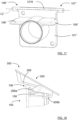
- Figure 4 shows a schematic front view of the vehicle camera module 100
- Figure 5 shows a schematic side view of the vehicle camera module 100.
- the vehicle camera module 100 comprises a housing 101 with a rear portion 102 and a front portion 103 that is adapted to face the vehicle windscreen 11.
- the vehicle camera module 100 further comprises a lens assembly 104 that at least partly is accommodated in the housing 101, and where the lens assembly 104 extends along a first extension L1 and comprises a lens aperture 105 that is closer to the front portion 103 than to the rear portion 102.
- an image sensor 117 is accommodated in the housing 101, where the image sensor 117 comprises an imaging surface 118 that is adapted to capture images that are transferred via the lens assembly 104.
- the first extension L1 runs perpendicular to the imaging surface 118, where a front-rear direction runs along the first extension L1 from the image sensor 117 towards the lens assembly 104.
- the housing 101 comprises a first holding section 106 and a second holding section 107 which holding sections 106, 107 protrude away from the first extension L1, where the housing 101 further comprises at least one holding rail 108, 109 extending between the rear portion 102 and the front portion 103.
- the holding rail 108, 109 extend in the rear to front direction.
- the housing 101 to be attached to another item, such as a camera mounting bracket that will be described later.
- a secure attachment is enabled, where the holding sections 106, 107 and said at least one holding rail 108, 109 can be integrated into the housing 101.
- the holding sections 106, 107 extend along a second extension L2 that runs perpendicular to a vertical plane P running along the first extension L1, the second extension L2 running in a left-right direction.
- An up-down direction runs perpendicular to the front-rear direction and the left-right direction.
- each holding section 106, 107 comprises a corresponding inner part 110a, 111a and outer part 110b, 111b, where each inner part 110a, 111a is closer to the vertical plane P than the corresponding outer part 110b, 111b.
- each inner part 110a, 111a has a largest cross-section area A1 that falls below a largest cross-section area A2 of the corresponding outer part 110b, 111b in a corresponding plane P1, P2 perpendicular to the second extension L2.
- Figure 2B shows the first holding section 106 as a separate part, it can of course be integrated with the housing as for example depicted in Figure 2A .
- the outer parts 110b, 111b thus a having a larger dimension, will provide a secure locking along the second extension L2 when the vehicle camera module 100 is mounted to another item.
- the outer parts 110b, 111b provide locking along the second extension L2. The locking depends on how the bracket is designed.
- each holding rail 108, 109 comprises a corresponding guide protrusion 114, 115.
- the intended function of the guide protrusions 114, 115 will be discussed more later.
- the housing 101 further comprises at least one guiding rail 112, 113 that extends between the rear portion 102 and the front portion 103. In this way, an increased stability is provided.
- the vehicle camera module 100 is adapted to be mounted to a vehicle camera mounting bracket 200 which now will be described more in detail.
- Figure 6 shows a schematic perspective back view of a vehicle camera mounting bracket according to a first example
- Figure 7 shows a schematic side view of the vehicle camera mounting bracket 200.
- the vehicle camera mounting bracket 200 comprises a main plate 201 with a longitudinal extension E, a first main side 202 that is adapted to be attached to a windscreen 11, and a second main side 203, opposite the first main side 202.
- the mounting bracket 200 comprises a first holding arrangement 204 and a second holding arrangement 205, the holding arrangements 204, 205 mainly extending parallel to the longitudinal extension E and extending from the second main side 203.
- each holding arrangement 204, 205 comprises a first hook-shaped receiving portion 206a, 207a and a second hook-shaped receiving portion 206b, 207b, where the receiving portions 206a, 207a; 206b, 207b are adapted to receive and releasably retain holding parts 106, 107 and holding rails 108, 109 of a vehicle camera module 101 according to the above.
- the first hook-shaped receiving portions 206a, 207a can engage the holding parts 106, 107 according to the above.
- the first hook-shaped receiving portions 206a, 207a comprises a first outer hook-shaped receiving portion 206a and a second outer hook-shaped receiving portion 207a, the first outer hook-shaped receiving portion 206a being adapted to engage the first holding part 106, and the second outer hook-shaped receiving portion 207a being adapted to engage the second holding part 107.
- the second hook-shaped receiving portions 206b, 207b comprises a first inner hook-shaped receiving portion 206b and a second inner hook-shaped receiving portion 207b, the first inner hook-shaped receiving portion 206b being adapted to engage and guide a first holding rail 108 and the second inner hook-shaped receiving portion 207b being adapted to engage and guide a second holding rail 109.
- the second hook-shaped receiving portions 206b, 207b are resilient, such that the holding rails 108, 109 can be engaged in a retaining manner.
- an inner portion is adapted be closer to a windscreen 11 than an outer portion.
- the vehicle camera mounting bracket 300 further comprises at least one resilient member 209, 210 that extends from the second main side 203.
- there is a first resilient member 209 and a second resilient member where, during mounting of the vehicle camera module 100 to the vehicle camera mounting bracket 200, a first inner part 110a of the first holding part 106 is adapted to press the first resilient member 209 towards the second main side 203, and where a second inner part 111a of the second holding part 107 is adapted to press the second resilient member 210 towards the second main side 203.
- the vehicle camera mounting bracket 300 further comprises one or more limiting ridges 215, 216 that extend from the second main side 203 and are adapted to limit the extent to which the resilient members 209, 210 can be pressed towards the second main side 203. In this manner, the resilient members 209, 210 are prevented from being deformed during mounting.
- each holding arrangement 204, 205 comprises a corresponding guiding portion 211, 212 that is adapted to guide guiding rails of a vehicle camera module.
- first guiding portion 211 and a second guiding portion 212 there is a first guiding portion 211 and a second guiding portion 212, where the first guiding portion 211 is adapted to engage and guide a first guiding rail 112, and where the second guiding portion 212 is adapted to engage and guide a second guiding rail 113.
- the guiding rails 112, 113 are comprised in the housing 101 of the vehicle camera module 100 according to the above. This way, mounting of the vehicle camera module 100 to the vehicle camera mounting bracket 300 is simplified.
- each holding arrangement 204, 205 comprises a corresponding groove 213, 214 extending along its holding arrangement 204, 205, the grooves 204, 205 being adapted to guide guide protrusions of a vehicle camera module towards the corresponding second hook-shaped receiving portion 206b, 207b.
- the first holding arrangement 204 comprises a first groove 213 and the second holding arrangement 205 comprises a second groove 214.
- the first groove 213 is adapted to engage and guide a first guide protrusion 114
- the second groove 214 is adapted to engage and guide a second guide protrusion 115.
- the grooves 204, 205 have the same shape.
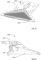
- the vehicle camera arrangement 300 is formed as shown in Figure 8 that shows a schematic perspective front view of a vehicle camera arrangement according to a first example, Figure 9 that shows a schematic perspective back view of the vehicle camera arrangement, and Figure 10 that shows a schematic side view of the vehicle camera arrangement.
- the vehicle camera arrangement 300 comprises the vehicle camera module 100 according to the above and the vehicle camera mounting bracket 200 according to the above, where the first hook-shaped receiving portions 206a, 207a have received a corresponding holding section 106, 107, and where the second hook-shaped receiving portions 206b, 207b have received a corresponding holding rail 108, 109.
- said resilient member 209, 210 presses against at least one holding section 106, 107 such that the holding sections 106, 107 are retained in the first hook-shaped receiving portions 206a, 207a.
- the first resilient member 209 presses against the first inner part 110a of the first holding part 106
- the second resilient member 210 presses against the second inner part 111a of the second holding part 107.
- the vehicle camera module 100 is securely retained in the vehicle camera mounting bracket 200, and in particular the holding sections 106, 107 are securely retained in the first hook-shaped receiving portions 206a, 207a.
- the second hook-shaped receiving portions 206b, 207b resiliently press against the holding rails 108, 109.
- Figure 11 shows a perspective front view of an alternative vehicle camera arrangement illustrates alternative grooves.
- Figure 12 - Figure 14 illustrate a second example of a vehicle camera arrangement, where Figure 12 shows a schematic perspective front view of a vehicle camera module 100' according to the second example, Figure 13 shows a schematic perspective back view of a vehicle camera mounting bracket 200' according to the second example, and Figure 14 shows a schematic side view of a camera arrangement according to the second example.
- the inner parts 110a', 111a' are comprised in a common rod 1116 that runs along the second extension L2. This provides increased stability.
- the housing 101' further comprises a wedge-shaped guide portion 1120 that has a dimension that increases from the front portion 103 to the rear portion 102. This facilitates insertion in the bracket.
- the vehicle camera mounting bracket 200' further comprises at least one wedge-shaped guide portion 1221, 1222 that extends from the second main side 203' and is adapted to guide the wedge-shaped guide portion 1120 of the vehicle camera module 100'. This means that insertion in the bracket is facilitated since the housing 101' can be easily guided into the correct position when mounted to the camera mounting bracket 200'.
- the above parts can be used in combination with, or instead of, the guiding portions 211, 212 and the guiding rails 112, 113 described above.
- each corresponding grove 1314 comprises a corresponding bulge 1330 that is adapted to get in retaining contact with a corresponding holding rail of a vehicle camera module. This means that each bulge 1330 will press against a corresponding holding rail 108', 109' of the camera module 100'.
- the camera module 100' is secured against the mounting bracket 200' both in the up-down direction and in the left-right direction.
- Figure 17 shows a schematic perspective front view of a vehicle camera module housing part according to a third example.
- the holding sections 106", 107" are constituted by a common rod 1216 that runs along the second extension L2.
- FIG. 18 shows a schematic side view of a vehicle camera arrangement at a first mounting step
- Figure 19 shows a schematic side view of a vehicle camera arrangement at a second mounting step
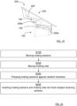
- Figure 20 shows a flowchart for methods according to the present disclosure.
- the present disclosure thus relates to a method for mounting a vehicle camera module 100 according to the above, to a vehicle camera mounting bracket according to the above.
- the method comprises moving S100 the holding sections 106, 107 towards the first hook-shaped receiving portions 206a, 207a, moving S200 the holding rails 108, 109 towards the second hook-shaped receiving portions 206b, 207b and pressing S300 the holding sections 106, 107 against the resilient members 209, 210 such that the resilient members 209, 210 admit passage of the holding sections 106, 107 as indicated in Figure 18 .
- the method further comprises inserting S400 the holding sections 106, 107 and holding rails 108, 109 into the corresponding hook-shaped receiving portions 206a, 207a; 206b, 207b such that the resilient members 209, 210 press against the holding sections 106, 107 to be releasably retained in the first hook-shaped receiving portions 206a, 207a as indicated in Figure 19 .
- the vehicle camera arrangement 1300 can further be equipped with a light trap 1223 as shown in Figure 15 that shows a schematic perspective front view of a vehicle camera module 101' with a light trap 1223 and Figure 16 that shows a schematic perspective rear view of a vehicle camera module 101' with a light trap 1223.
- the light trap 1223 is attached to the vehicle camera mounting bracket 200' such that the vehicle camera mounting bracket 200' is equipped with the light trap 1223.
- the mounting direction of the vehicle camera module 101' will allow the lens assembly to enter an opening in the light trap 1223.
Landscapes
- Engineering & Computer Science (AREA)
- Mechanical Engineering (AREA)
- Fittings On The Vehicle Exterior For Carrying Loads, And Devices For Holding Or Mounting Articles (AREA)
Abstract
Description
- The present disclosure relates to a vehicle camera module and a vehicle camera mounting bracket, and to a vehicle camera arrangement comprising the vehicle camera module and the vehicle camera mounting bracket.
- Many vehicle environment detection systems comprise one or more sensors such as for example radar sensor, LIDAR sensors, ultrasonic sensors and digital camera devices. These are used for collecting data used for safety arrangements as well as for driver assistance systems. A camera device is adapted to collect images of the surroundings, and may be used to identify landmarks.
- For a digital camera device, that can be in the form of, or comprised in, a vehicle imaging system, a camera module is mounted to a camera mounting bracket that in turn is mounted to a vehicle. The camera module comprises a housing, a lens assembly and a PCB to which an image sensor and associated components are mounted.
- It is an object of the present disclosure to provide means for a secure, efficient and reliable mounting of the camera module to the camera mounting bracket and thus to a vehicle.
- Said object is achieved by means of a vehicle camera module that comprises a housing with a rear portion and a front portion that is adapted to face a vehicle windscreen, and a lens assembly that at least partly is accommodated in the housing. The lens assembly extends along a first extension and comprises a lens aperture that is closer to the front portion than to the rear portion. The housing comprises a first holding section and a second holding section which holding sections protrude away from the first extension. The housing further comprises at least one holding rail extending between the rear portion and the front portion.
- This enables the housing to be attached to another item, such as a camera mounting bracket. By means of the holding sections and said at least one holding rail, a secure attachment is enabled, where the holding sections and said at least one holding rail can be integrated into the housing.
- According to some aspects, the holding sections extend along a second extension that runs perpendicular to a vertical plane running along the first extension.
- In this way, the holding sections are arranged along a line which will enable an uncomplicated mounting to another item, such as a camera mounting bracket.
- According to some aspects, each holding section comprises a corresponding inner part and outer part. Each inner part is closer to the vertical plane than the corresponding outer part.
- According to some aspects, each inner part has a largest cross-section area that falls below a largest cross-section area of the corresponding outer part in a corresponding plane perpendicular to the second extension.
- This will provide a secure locking along the second extension when the vehicle camera module is mounted to another item. In particular, the outer parts will provide locking along the second extension.
- According to some aspects, the housing further comprises at least one guiding rail that extends between the rear portion and the front portion. In this way, an increased stability is provided.
- Said object is also achieved by means of a vehicle camera mounting bracket comprising a main plate with a longitudinal extension, a first main side that is adapted to be attached to a windscreen, and a second main side, opposite the first main side. The mounting bracket comprises a first holding arrangement and a second holding arrangement, the holding arrangements mainly extending parallel to the longitudinal extension and extending from the second main side. Each holding arrangement comprises a first hook-shaped receiving portion and a second hook-shaped receiving portion. The receiving portions are adapted to receive and releasably retain holding parts of a vehicle camera module.
- This means that the first hook-shaped receiving portions can engage the holding parts according to the above
- According to some aspects, the vehicle camera mounting bracket further comprises at least one resilient member that extends from the second main side.
- According to some aspects, each holding arrangement comprises a corresponding guiding portion that is adapted to guide guiding rails of a vehicle camera module. This way, mounting of a vehicle camera module to the vehicle camera mounting bracket is simplified.
- According to some aspects, each holding arrangement comprises a corresponding groove extending along its holding arrangement.
- The grooves are adapted to guide guide protrusions of a vehicle camera module towards the corresponding second hook-shaped receiving portion.
- According to some aspects, the second hook-shaped receiving portions are resilient. In this way, holding rails of a vehicle camera module can be engaged in a retaining manner.
- This object is also achieved by means of vehicle camera arrangements comprising the vehicle camera module and the vehicle camera mounting bracket according to the above, and also methods, which all are associated with the above advantages.
- The present disclosure will now be described more in detail with reference to the appended drawings, where:
- Figure 1
- shows a schematic cut-open part of a vehicle with a camera device;
- Figure 2A
- shows a schematic perspective front view of a vehicle camera module according to a first example;
- Figure 2B
- shows details of a holding section;
- Figure 3
- shows a schematic top view of the vehicle camera module;
- Figure 4
- shows a schematic front view of the vehicle camera module;
- Figure 5
- shows a schematic side view of the vehicle camera module;
- Figure 6
- shows a schematic perspective back view of a vehicle camera mounting bracket according to a first example;
- Figure 7
- shows a schematic side view of the vehicle camera mounting bracket;
- Figure 8
- shows a schematic perspective front view of a vehicle camera arrangement according to a first example;
- Figure 9
- shows a schematic perspective back view of the vehicle camera arrangement;
- Figure 10
- shows a schematic side view of the vehicle camera arrangement;
- Figure 11
- shows a schematic perspective front view of an alternative vehicle camera arrangement;
- Figure 12
- shows a schematic perspective front view of a vehicle camera module according to a second example;
- Figure 13
- shows a schematic perspective back view of a vehicle camera mounting bracket according to a second example;
- Figure 14
- shows a schematic side view of a camera arrangement according to the second example;
- Figure 15
- shows a schematic perspective front view of a vehicle camera module with a light trap;
- Figure 16
- shows a schematic perspective rear view of a vehicle camera module with a light trap;
- Figure 17
- shows a schematic perspective front view of a vehicle camera module housing according to a third example;
- Figure 18
- shows a schematic side view of a vehicle camera arrangement at a first mounting step;
- Figure 19
- shows a schematic side view of a vehicle camera arrangement at a second mounting step; and
- Figure 20
- shows a flowchart for methods according to the present disclosure.
- Aspects of the present disclosure will now be described more fully hereinafter with reference to the accompanying drawings. The different devices, systems, computer programs and methods disclosed herein can, however, be realized in many different forms and should not be construed as being limited to the aspects set forth herein. Like numbers in the drawings refer to like elements throughout.
- The terminology used herein is for describing aspects of the disclosure only and is not intended to limit the invention. As used herein, the singular forms "a", "an" and "the" are intended to include the plural forms as well, unless the context clearly indicates otherwise.
-
Figure 1 schematically shows a cut-open part of avehicle 10, where thevehicle 10 comprises avehicle camera arrangement 300 attached to avehicle windscreen 11. Thevehicle camera arrangement 300 is arranged for capturing images of the surroundings outside thevehicle 10 by means of a certain field ofview 12. Thevehicle camera arrangement 300 can also, or alternatively, be arranged for capturing images of adriver 13, where these images, which may include eye movements, for example can be used for detecting a degree of driver drowsiness. - As shown in
Figure 8 - Figure 10 , thevehicle camera arrangement 300 comprises avehicle camera module 100 and a vehiclecamera mounting bracket 200, and the present disclosure is directed to thevehicle camera arrangement 300 as well as to thevehicle camera module 100 and the vehiclecamera mounting bracket 200 separately. - In the following, a first example the
vehicle camera module 100 will be described with reference toFigure 2 - Figure 5 , and then a corresponding vehiclecamera mounting bracket 200 will be described with reference toFigure 6 andFigure 7 . -
Figure 2A shows a schematic perspective front view of avehicle camera module 100 according to a first example,Figure 2B shows details of aholding section 106,Figure 3 shows a schematic top view of thevehicle camera module 100,Figure 4 shows a schematic front view of thevehicle camera module 100, andFigure 5 shows a schematic side view of thevehicle camera module 100. - The
vehicle camera module 100 comprises ahousing 101 with arear portion 102 and afront portion 103 that is adapted to face thevehicle windscreen 11. Thevehicle camera module 100 further comprises alens assembly 104 that at least partly is accommodated in thehousing 101, and where thelens assembly 104 extends along a first extension L1 and comprises alens aperture 105 that is closer to thefront portion 103 than to therear portion 102. - According to some aspects, an
image sensor 117 is accommodated in thehousing 101, where theimage sensor 117 comprises animaging surface 118 that is adapted to capture images that are transferred via thelens assembly 104. According to some aspects, the first extension L1 runs perpendicular to theimaging surface 118, where a front-rear direction runs along the first extension L1 from theimage sensor 117 towards thelens assembly 104. - According to the present disclosure, the
housing 101 comprises afirst holding section 106 and asecond holding section 107 which holdingsections housing 101 further comprises at least one holdingrail rear portion 102 and thefront portion 103. According to some aspects, the holdingrail - This enables the
housing 101 to be attached to another item, such as a camera mounting bracket that will be described later. By means of the holdingsections rail sections rail housing 101. - According to some aspects, the holding
sections Figure 2A ,Figure 8 andFigure 12 . The vertical plane P divides thelens assembly 104 into two parts that according to some aspects are symmetrical. In this way, the holdingsections - According to some aspects, each holding
section inner part outer part inner part outer part Figure 2B , eachinner part outer part Figure 2B shows thefirst holding section 106 as a separate part, it can of course be integrated with the housing as for example depicted inFigure 2A . - The
outer parts vehicle camera module 100 is mounted to another item. In particular, theouter parts - According to some aspects, each holding
rail corresponding guide protrusion guide protrusions - According to some aspects, the
housing 101 further comprises at least one guidingrail rear portion 102 and thefront portion 103. In this way, an increased stability is provided. - The
vehicle camera module 100 is adapted to be mounted to a vehiclecamera mounting bracket 200 which now will be described more in detail.Figure 6 shows a schematic perspective back view of a vehicle camera mounting bracket according to a first example, andFigure 7 shows a schematic side view of the vehiclecamera mounting bracket 200. - The vehicle
camera mounting bracket 200 comprises amain plate 201 with a longitudinal extension E, a firstmain side 202 that is adapted to be attached to awindscreen 11, and a secondmain side 203, opposite the firstmain side 202. The mountingbracket 200 comprises afirst holding arrangement 204 and asecond holding arrangement 205, the holdingarrangements main side 203. - In accordance with the present disclosure, each holding
arrangement receiving portion receiving portion portions parts rails vehicle camera module 101 according to the above. - This means that the first hook-shaped
receiving portions parts receiving portions receiving portion 206a and a second outer hook-shapedreceiving portion 207a, the first outer hook-shapedreceiving portion 206a being adapted to engage the first holdingpart 106, and the second outer hook-shapedreceiving portion 207a being adapted to engage thesecond holding part 107. The second hook-shaped receivingportions receiving portion 206b and a second inner hook-shapedreceiving portion 207b, the first inner hook-shapedreceiving portion 206b being adapted to engage and guide afirst holding rail 108 and the second inner hook-shapedreceiving portion 207b being adapted to engage and guide asecond holding rail 109. According to some aspects, the second hook-shaped receivingportions rails - In this context, an inner portion is adapted be closer to a
windscreen 11 than an outer portion. - According to some aspects, the vehicle
camera mounting bracket 300 further comprises at least oneresilient member main side 203. Here, there is a firstresilient member 209 and a second resilient member, where, during mounting of thevehicle camera module 100 to the vehiclecamera mounting bracket 200, a firstinner part 110a of the first holdingpart 106 is adapted to press the firstresilient member 209 towards the secondmain side 203, and where a secondinner part 111a of thesecond holding part 107 is adapted to press the secondresilient member 210 towards the secondmain side 203. - According to some aspects, the vehicle
camera mounting bracket 300 further comprises one or more limitingridges main side 203 and are adapted to limit the extent to which theresilient members main side 203. In this manner, theresilient members - According to some aspects, each holding
arrangement corresponding guiding portion first guiding portion 211 and asecond guiding portion 212, where thefirst guiding portion 211 is adapted to engage and guide afirst guiding rail 112, and where thesecond guiding portion 212 is adapted to engage and guide asecond guiding rail 113. The guiding rails 112, 113 are comprised in thehousing 101 of thevehicle camera module 100 according to the above. This way, mounting of thevehicle camera module 100 to the vehiclecamera mounting bracket 300 is simplified. - According to some aspects, each holding
arrangement corresponding groove arrangement grooves receiving portion first holding arrangement 204 comprises afirst groove 213 and thesecond holding arrangement 205 comprises asecond groove 214. Thefirst groove 213 is adapted to engage and guide afirst guide protrusion 114, and thesecond groove 214 is adapted to engage and guide asecond guide protrusion 115. In this example, thegrooves - When the
vehicle camera module 100 is mounted to the vehiclecamera mounting bracket 200, thevehicle camera arrangement 300 is formed as shown inFigure 8 that shows a schematic perspective front view of a vehicle camera arrangement according to a first example,Figure 9 that shows a schematic perspective back view of the vehicle camera arrangement, andFigure 10 that shows a schematic side view of the vehicle camera arrangement. - The
vehicle camera arrangement 300 comprises thevehicle camera module 100 according to the above and the vehiclecamera mounting bracket 200 according to the above, where the first hook-shapedreceiving portions corresponding holding section portions rail - According to some aspects, said
resilient member holding section sections receiving portions resilient member 209 presses against the firstinner part 110a of the first holdingpart 106, and the secondresilient member 210 presses against the secondinner part 111a of thesecond holding part 107. In this manner, thevehicle camera module 100 is securely retained in the vehiclecamera mounting bracket 200, and in particular the holdingsections receiving portions - According to some aspects, the second hook-shaped receiving
portions rails -
Figure 11 shows a perspective front view of an alternative vehicle camera arrangement illustrates alternative grooves. There is an alternativecamera mounting bracket 300a where afirst groove 213a is flat and asecond groove 214a is V-shaped, where theguide protrusions respective groove -
Figure 12 - Figure 14 illustrate a second example of a vehicle camera arrangement, whereFigure 12 shows a schematic perspective front view of a vehicle camera module 100' according to the second example,Figure 13 shows a schematic perspective back view of a vehicle camera mounting bracket 200' according to the second example, andFigure 14 shows a schematic side view of a camera arrangement according to the second example. - According to some aspects, the
inner parts 110a', 111a' are comprised in acommon rod 1116 that runs along the second extension L2. This provides increased stability. - According to some aspects, the housing 101' further comprises a wedge-shaped
guide portion 1120 that has a dimension that increases from thefront portion 103 to therear portion 102. This facilitates insertion in the bracket. - According to some aspects, the vehicle camera mounting bracket 200' further comprises at least one wedge-shaped
guide portion guide portion 1120 of the vehicle camera module 100'. This means that insertion in the bracket is facilitated since the housing 101' can be easily guided into the correct position when mounted to the camera mounting bracket 200'. - The above parts can be used in combination with, or instead of, the guiding
portions rails - According to some aspects, each corresponding
grove 1314 comprises acorresponding bulge 1330 that is adapted to get in retaining contact with a corresponding holding rail of a vehicle camera module. This means that eachbulge 1330 will press against a corresponding holding rail 108', 109' of the camera module 100'. - Here, the camera module 100' is secured against the mounting bracket 200' both in the up-down direction and in the left-right direction.
-
Figure 17 shows a schematic perspective front view of a vehicle camera module housing part according to a third example. Here, according to some aspects, the holdingsections 106", 107" are constituted by acommon rod 1216 that runs along the second extension L2. - The mounting of the
vehicle camera module 100 to the vehiclecamera mounting bracket 200 will now be described with reference toFigure 18 that shows a schematic side view of a vehicle camera arrangement at a first mounting step,Figure 19 that shows a schematic side view of a vehicle camera arrangement at a second mounting step, andFigure 20 that shows a flowchart for methods according to the present disclosure. - The present disclosure thus relates to a method for mounting a
vehicle camera module 100 according to the above, to a vehicle camera mounting bracket according to the above. The method comprises moving S100 the holdingsections receiving portions rails portions sections resilient members resilient members sections Figure 18 . The method further comprises inserting S400 the holdingsections rails receiving portions resilient members sections receiving portions Figure 19 . - The present disclosure is not limited to the examples above, but may vary freely within the scope of the appended claims. For example, the
vehicle camera arrangement 1300 can further be equipped with alight trap 1223 as shown inFigure 15 that shows a schematic perspective front view of a vehicle camera module 101' with alight trap 1223 andFigure 16 that shows a schematic perspective rear view of a vehicle camera module 101' with alight trap 1223. - The
light trap 1223 is attached to the vehicle camera mounting bracket 200' such that the vehicle camera mounting bracket 200' is equipped with thelight trap 1223. The mounting direction of the vehicle camera module 101' will allow the lens assembly to enter an opening in thelight trap 1223.
Claims (15)
- A vehicle camera module (100) that comprises a housing (101) with a rear portion (102) and a front portion (103) that is adapted to face a vehicle windscreen, and a lens assembly (104) that at least partly is accommodated in the housing (101), and where the lens assembly (104) extends along a first extension (L1) and comprises a lens aperture (105) that is closer to the front portion (103) than to the rear portion (104), characterized in that- the housing (101) comprises a first holding section (106) and a second holding section (107) which holding sections (106, 107) protrude away from the first extension (L1),- the housing (101) further comprises at least one holding rail (108, 109) extending between the rear portion (102) and the front portion (103).
- The vehicle camera module (100) according to claim 1, wherein the holding sections (106, 107) extend along a second extension (L2) that runs perpendicular to a vertical plane (P) running along the first extension (L1).
- The vehicle camera module (100) according to claim 2, wherein each holding section (106, 107) comprises a corresponding inner part (110a, 111a) and outer part (110b, 111b), where each inner part (110a, 111a) is closer to the vertical plane (P) than the corresponding outer part (110b, 111b) .
- The vehicle camera module (100) according to claim 3, wherein each inner part (110a, 111a) has a largest cross-section area (A1) that falls below a largest cross-section area (A2) of the corresponding outer part (110b, 111b) in a corresponding plane (P1, P2) perpendicular to the second extension (L2).
- The vehicle camera module (100) according to any one of the previous claims, wherein each holding rail (108, 109) comprises a corresponding guide protrusion (114, 115).
- The vehicle camera module (100) according to any one of the previous claims, wherein the housing (101) further comprises at least one guiding rail (112, 113) that extends between the rear portion (102) and the front portion (103).
- A vehicle camera mounting bracket (200) comprising a main plate (201) with a longitudinal extension (E), a first main side (202) that is adapted to be attached to a windscreen (11), and a second main side (203), opposite the first main side (202), where the mounting bracket (200) comprises a first holding arrangement (204) and a second holding arrangement (205), the holding arrangements (204, 205) mainly extending parallel to the longitudinal extension (E) and extending from the second main side (203), characterized in that each holding arrangement (204, 205) comprises a first hook-shaped receiving portion (206a, 207a) and a second hook-shaped receiving portion (206b, 207b), the receiving portions (206a, 207a; 206b, 207b) being adapted to receive and releasably retain holding parts of a vehicle camera module.
- The vehicle camera mounting bracket (200) according to claim 7, further comprising at least one resilient member (209, 210) that extends from the second main side (203).
- The vehicle camera mounting bracket (200) according to any one of the claims 7 or 8, wherein each holding arrangement (204, 205) comprises a corresponding guiding portion (211, 212) that is adapted to guide guiding rails of a vehicle camera module.
- The vehicle camera mounting bracket (200) according to any one of the claims 7-9, wherein each holding arrangement (204, 205) comprises a corresponding groove (213, 214) extending along its holding arrangement (204, 205), the grooves (213, 214) being adapted to guide guide protrusions of a vehicle camera module towards the corresponding second hook-shaped receiving portion (206b, 207b).
- The vehicle camera mounting bracket (200') according to claim 10, wherein each corresponding groove (1314) comprises a corresponding bulge (1330) that is adapted to get in retaining contact with a corresponding holding rail of a vehicle camera module.
- The vehicle camera mounting bracket (200) according to any one of the claims 7-11, wherein the second hook-shaped receiving portions (206b, 207b) are resilient.
- A vehicle camera arrangement (300) comprising the vehicle camera module according to any one of the claims 1-6 and the vehicle camera mounting bracket according to any one of the claims 7-12, where the first hook-shaped receiving portions (206a, 207a) have received a corresponding holding section (106, 107), and where the second hook-shaped receiving portions (206b, 207b) have received a corresponding holding rail (108, 109).
- The vehicle camera arrangement (300) according to claim 13, wherein said resilient member (209, 210) presses against at least one holding section (106, 107) such that the holding sections (106, 107) are retained in the first hook-shaped receiving portions (206a, 207a).
- A method for mounting a vehicle camera module (100), according to any one of the claims 1-6, to a vehicle camera mounting bracket, according to any one of the claims 7-12, where the method comprises:moving (S100) the holding sections (106, 107) towards the first hook-shaped receiving portions (206a, 207a);moving (S200) the holding rails (108, 109) towards the second hook-shaped receiving portions (206b, 207b);pressing (S300) the holding sections (106, 107) against the resilient members (209, 210) such that the resilient members (209, 210) admit passage of the holding sections (106, 107);inserting (S400) the holding sections (106, 107) and holding rails (108, 109) into the corresponding hook-shaped receiving portions (206a, 207a; 206b, 207b) such that the resilient members (209, 210) press against the holding sections (106, 107) to be releasably retained in the first hook-shaped receiving portions (206a, 207a).
Priority Applications (2)
| Application Number | Priority Date | Filing Date | Title |
|---|---|---|---|
| EP22156797.7A EP4227164B1 (en) | 2022-02-15 | 2022-02-15 | A vehicle camera arrangement, a vehicle camera module and a vehicle camera mounting bracket |
| PCT/EP2023/053750 WO2023156451A1 (en) | 2022-02-15 | 2023-02-15 | A vehicle camera arrangement, a vehicle camera module and a vehicle camera mounting bracket |
Applications Claiming Priority (1)
| Application Number | Priority Date | Filing Date | Title |
|---|---|---|---|
| EP22156797.7A EP4227164B1 (en) | 2022-02-15 | 2022-02-15 | A vehicle camera arrangement, a vehicle camera module and a vehicle camera mounting bracket |
Publications (2)
| Publication Number | Publication Date |
|---|---|
| EP4227164A1 true EP4227164A1 (en) | 2023-08-16 |
| EP4227164B1 EP4227164B1 (en) | 2025-01-29 |
Family
ID=80682965
Family Applications (1)
| Application Number | Title | Priority Date | Filing Date |
|---|---|---|---|
| EP22156797.7A Active EP4227164B1 (en) | 2022-02-15 | 2022-02-15 | A vehicle camera arrangement, a vehicle camera module and a vehicle camera mounting bracket |
Country Status (2)
| Country | Link |
|---|---|
| EP (1) | EP4227164B1 (en) |
| WO (1) | WO2023156451A1 (en) |
Citations (6)
| Publication number | Priority date | Publication date | Assignee | Title |
|---|---|---|---|---|
| JP2013186278A (en) * | 2012-03-08 | 2013-09-19 | Honda Motor Co Ltd | Camera unit |
| EP2965949A1 (en) * | 2014-07-10 | 2016-01-13 | Toyota Jidosha Kabushiki Kaisha | Attachment structure for in-vehicle camera |
| EP3527429A1 (en) * | 2018-02-15 | 2019-08-21 | Aptiv Technologies Limited | Module and support structure assembly |
| US10556553B2 (en) * | 2018-05-15 | 2020-02-11 | Veoneer Us, Inc. | Vehicle camera mounting interfaces |
| EP3770021A1 (en) * | 2019-07-25 | 2021-01-27 | Nifco Inc. | Bracket for in-vehicle device and holding device for in-vehicle device |
| WO2021038201A1 (en) * | 2019-08-23 | 2021-03-04 | Pilkington Group Limited | Windscreen |
-
2022
- 2022-02-15 EP EP22156797.7A patent/EP4227164B1/en active Active
-
2023
- 2023-02-15 WO PCT/EP2023/053750 patent/WO2023156451A1/en not_active Ceased
Patent Citations (6)
| Publication number | Priority date | Publication date | Assignee | Title |
|---|---|---|---|---|
| JP2013186278A (en) * | 2012-03-08 | 2013-09-19 | Honda Motor Co Ltd | Camera unit |
| EP2965949A1 (en) * | 2014-07-10 | 2016-01-13 | Toyota Jidosha Kabushiki Kaisha | Attachment structure for in-vehicle camera |
| EP3527429A1 (en) * | 2018-02-15 | 2019-08-21 | Aptiv Technologies Limited | Module and support structure assembly |
| US10556553B2 (en) * | 2018-05-15 | 2020-02-11 | Veoneer Us, Inc. | Vehicle camera mounting interfaces |
| EP3770021A1 (en) * | 2019-07-25 | 2021-01-27 | Nifco Inc. | Bracket for in-vehicle device and holding device for in-vehicle device |
| WO2021038201A1 (en) * | 2019-08-23 | 2021-03-04 | Pilkington Group Limited | Windscreen |
Also Published As
| Publication number | Publication date |
|---|---|
| EP4227164B1 (en) | 2025-01-29 |
| WO2023156451A1 (en) | 2023-08-24 |
Similar Documents
| Publication | Publication Date | Title |
|---|---|---|
| US11603049B2 (en) | Vehicular camera with thermally conductive material disposed between and contacting stacked PCBs | |
| US11809072B2 (en) | Vehicle camera holding device | |
| US8944705B1 (en) | Camera unit | |
| US11275227B2 (en) | Camera for vehicle vision system with replaceable lens | |
| JP6678124B2 (en) | In-vehicle imaging device | |
| US20250116841A1 (en) | Method for assembling imager assembly for vehicular camera | |
| US6531959B1 (en) | Position detecting device | |
| CN103608722B (en) | Camera system for vehicle | |
| US11945375B2 (en) | Onboard camera holding method, onboard camera, bracket | |
| CN112793517A (en) | Sensor mounting structure | |
| CN110371042B (en) | Attachment unit and attachment method for a vehicle component and windshield for a vehicle | |
| EP1069536A2 (en) | Stereo type vehicle monitoring apparatus with fail-safe function | |
| US20150042798A1 (en) | In-vehicle camera | |
| KR102420289B1 (en) | Method, control device and vehicle for detecting at least one object present on a vehicle | |
| CN105936242A (en) | In-vehicle sensor mounting structure | |
| CN105292009A (en) | Attachment structure for in-vehicle camera | |
| JP7566199B2 (en) | Camera unit and passenger monitoring system | |
| KR20170128727A (en) | Apparatus and method for auto-correcting and generating avm image | |
| US20200346589A1 (en) | Telecamera for a vehicle and fastening of a telecamera to the vehicle | |
| CN114731374A (en) | Camera image and sensor fusion for mirror exchange system | |
| EP4227164B1 (en) | A vehicle camera arrangement, a vehicle camera module and a vehicle camera mounting bracket | |
| US11987185B2 (en) | Windscreen | |
| EP3461689B1 (en) | Camera device and method for mounting a camera device for a motor vehicle | |
| JP2022551553A (en) | vehicle camera module | |
| US20240364985A1 (en) | Imaging device |
Legal Events
| Date | Code | Title | Description |
|---|---|---|---|
| PUAI | Public reference made under article 153(3) epc to a published international application that has entered the european phase |
Free format text: ORIGINAL CODE: 0009012 |
|
| STAA | Information on the status of an ep patent application or granted ep patent |
Free format text: STATUS: THE APPLICATION HAS BEEN PUBLISHED |
|
| AK | Designated contracting states |
Kind code of ref document: A1 Designated state(s): AL AT BE BG CH CY CZ DE DK EE ES FI FR GB GR HR HU IE IS IT LI LT LU LV MC MK MT NL NO PL PT RO RS SE SI SK SM TR |
|
| STAA | Information on the status of an ep patent application or granted ep patent |
Free format text: STATUS: REQUEST FOR EXAMINATION WAS MADE |
|
| 17P | Request for examination filed |
Effective date: 20240202 |
|
| RBV | Designated contracting states (corrected) |
Designated state(s): AL AT BE BG CH CY CZ DE DK EE ES FI FR GB GR HR HU IE IS IT LI LT LU LV MC MK MT NL NO PL PT RO RS SE SI SK SM TR |
|
| RAP3 | Party data changed (applicant data changed or rights of an application transferred) |
Owner name: MAGNA ELECTRONICS SWEDEN AB |
|
| RAP3 | Party data changed (applicant data changed or rights of an application transferred) |
Owner name: MAGNA ELECTRONICS SWEDEN AB |
|
| GRAP | Despatch of communication of intention to grant a patent |
Free format text: ORIGINAL CODE: EPIDOSNIGR1 |
|
| STAA | Information on the status of an ep patent application or granted ep patent |
Free format text: STATUS: GRANT OF PATENT IS INTENDED |
|
| INTG | Intention to grant announced |
Effective date: 20240909 |
|
| GRAS | Grant fee paid |
Free format text: ORIGINAL CODE: EPIDOSNIGR3 |
|
| GRAA | (expected) grant |
Free format text: ORIGINAL CODE: 0009210 |
|
| STAA | Information on the status of an ep patent application or granted ep patent |
Free format text: STATUS: THE PATENT HAS BEEN GRANTED |
|
| AK | Designated contracting states |
Kind code of ref document: B1 Designated state(s): AL AT BE BG CH CY CZ DE DK EE ES FI FR GB GR HR HU IE IS IT LI LT LU LV MC MK MT NL NO PL PT RO RS SE SI SK SM TR |
|
| REG | Reference to a national code |
Ref country code: GB Ref legal event code: FG4D |
|
| REG | Reference to a national code |
Ref country code: CH Ref legal event code: EP |
|
| REG | Reference to a national code |
Ref country code: DE Ref legal event code: R096 Ref document number: 602022009901 Country of ref document: DE |
|
| REG | Reference to a national code |
Ref country code: IE Ref legal event code: FG4D |
|
| PGFP | Annual fee paid to national office [announced via postgrant information from national office to epo] |
Ref country code: AT Payment date: 20250417 Year of fee payment: 4 |
|
| REG | Reference to a national code |
Ref country code: NL Ref legal event code: MP Effective date: 20250129 |
|
| PG25 | Lapsed in a contracting state [announced via postgrant information from national office to epo] |
Ref country code: NL Free format text: LAPSE BECAUSE OF FAILURE TO SUBMIT A TRANSLATION OF THE DESCRIPTION OR TO PAY THE FEE WITHIN THE PRESCRIBED TIME-LIMIT Effective date: 20250129 |
|
| PG25 | Lapsed in a contracting state [announced via postgrant information from national office to epo] |
Ref country code: RS Free format text: LAPSE BECAUSE OF FAILURE TO SUBMIT A TRANSLATION OF THE DESCRIPTION OR TO PAY THE FEE WITHIN THE PRESCRIBED TIME-LIMIT Effective date: 20250429 |
|
| PG25 | Lapsed in a contracting state [announced via postgrant information from national office to epo] |
Ref country code: FI Free format text: LAPSE BECAUSE OF FAILURE TO SUBMIT A TRANSLATION OF THE DESCRIPTION OR TO PAY THE FEE WITHIN THE PRESCRIBED TIME-LIMIT Effective date: 20250129 |
|
| PG25 | Lapsed in a contracting state [announced via postgrant information from national office to epo] |
Ref country code: PL Free format text: LAPSE BECAUSE OF FAILURE TO SUBMIT A TRANSLATION OF THE DESCRIPTION OR TO PAY THE FEE WITHIN THE PRESCRIBED TIME-LIMIT Effective date: 20250129 |
|
| PG25 | Lapsed in a contracting state [announced via postgrant information from national office to epo] |
Ref country code: ES Free format text: LAPSE BECAUSE OF FAILURE TO SUBMIT A TRANSLATION OF THE DESCRIPTION OR TO PAY THE FEE WITHIN THE PRESCRIBED TIME-LIMIT Effective date: 20250129 |
|
| REG | Reference to a national code |
Ref country code: LT Ref legal event code: MG9D |
|
| PG25 | Lapsed in a contracting state [announced via postgrant information from national office to epo] |
Ref country code: NO Free format text: LAPSE BECAUSE OF FAILURE TO SUBMIT A TRANSLATION OF THE DESCRIPTION OR TO PAY THE FEE WITHIN THE PRESCRIBED TIME-LIMIT Effective date: 20250429 Ref country code: IS Free format text: LAPSE BECAUSE OF FAILURE TO SUBMIT A TRANSLATION OF THE DESCRIPTION OR TO PAY THE FEE WITHIN THE PRESCRIBED TIME-LIMIT Effective date: 20250529 |
|
| REG | Reference to a national code |
Ref country code: AT Ref legal event code: MK05 Ref document number: 1763158 Country of ref document: AT Kind code of ref document: T Effective date: 20250129 |
|
| PG25 | Lapsed in a contracting state [announced via postgrant information from national office to epo] |
Ref country code: HR Free format text: LAPSE BECAUSE OF FAILURE TO SUBMIT A TRANSLATION OF THE DESCRIPTION OR TO PAY THE FEE WITHIN THE PRESCRIBED TIME-LIMIT Effective date: 20250129 |
|
| PG25 | Lapsed in a contracting state [announced via postgrant information from national office to epo] |
Ref country code: PT Free format text: LAPSE BECAUSE OF FAILURE TO SUBMIT A TRANSLATION OF THE DESCRIPTION OR TO PAY THE FEE WITHIN THE PRESCRIBED TIME-LIMIT Effective date: 20250529 Ref country code: LV Free format text: LAPSE BECAUSE OF FAILURE TO SUBMIT A TRANSLATION OF THE DESCRIPTION OR TO PAY THE FEE WITHIN THE PRESCRIBED TIME-LIMIT Effective date: 20250129 |
|
| PG25 | Lapsed in a contracting state [announced via postgrant information from national office to epo] |
Ref country code: GR Free format text: LAPSE BECAUSE OF FAILURE TO SUBMIT A TRANSLATION OF THE DESCRIPTION OR TO PAY THE FEE WITHIN THE PRESCRIBED TIME-LIMIT Effective date: 20250430 Ref country code: BG Free format text: LAPSE BECAUSE OF FAILURE TO SUBMIT A TRANSLATION OF THE DESCRIPTION OR TO PAY THE FEE WITHIN THE PRESCRIBED TIME-LIMIT Effective date: 20250129 |
|
| PG25 | Lapsed in a contracting state [announced via postgrant information from national office to epo] |
Ref country code: AT Free format text: LAPSE BECAUSE OF FAILURE TO SUBMIT A TRANSLATION OF THE DESCRIPTION OR TO PAY THE FEE WITHIN THE PRESCRIBED TIME-LIMIT Effective date: 20250129 |
|
| PG25 | Lapsed in a contracting state [announced via postgrant information from national office to epo] |
Ref country code: SE Free format text: LAPSE BECAUSE OF FAILURE TO SUBMIT A TRANSLATION OF THE DESCRIPTION OR TO PAY THE FEE WITHIN THE PRESCRIBED TIME-LIMIT Effective date: 20250129 |
|
| REG | Reference to a national code |
Ref country code: CH Ref legal event code: PL |
|
| PG25 | Lapsed in a contracting state [announced via postgrant information from national office to epo] |
Ref country code: SM Free format text: LAPSE BECAUSE OF FAILURE TO SUBMIT A TRANSLATION OF THE DESCRIPTION OR TO PAY THE FEE WITHIN THE PRESCRIBED TIME-LIMIT Effective date: 20250129 |
|
| PG25 | Lapsed in a contracting state [announced via postgrant information from national office to epo] |
Ref country code: DK Free format text: LAPSE BECAUSE OF FAILURE TO SUBMIT A TRANSLATION OF THE DESCRIPTION OR TO PAY THE FEE WITHIN THE PRESCRIBED TIME-LIMIT Effective date: 20250129 |
|
| PG25 | Lapsed in a contracting state [announced via postgrant information from national office to epo] |
Ref country code: MC Free format text: LAPSE BECAUSE OF FAILURE TO SUBMIT A TRANSLATION OF THE DESCRIPTION OR TO PAY THE FEE WITHIN THE PRESCRIBED TIME-LIMIT Effective date: 20250129 |
|
| PG25 | Lapsed in a contracting state [announced via postgrant information from national office to epo] |
Ref country code: LU Free format text: LAPSE BECAUSE OF NON-PAYMENT OF DUE FEES Effective date: 20250215 Ref country code: IT Free format text: LAPSE BECAUSE OF FAILURE TO SUBMIT A TRANSLATION OF THE DESCRIPTION OR TO PAY THE FEE WITHIN THE PRESCRIBED TIME-LIMIT Effective date: 20250129 |
|
| PG25 | Lapsed in a contracting state [announced via postgrant information from national office to epo] |
Ref country code: CH Free format text: LAPSE BECAUSE OF NON-PAYMENT OF DUE FEES Effective date: 20250228 |
|
| PG25 | Lapsed in a contracting state [announced via postgrant information from national office to epo] |
Ref country code: CZ Free format text: LAPSE BECAUSE OF FAILURE TO SUBMIT A TRANSLATION OF THE DESCRIPTION OR TO PAY THE FEE WITHIN THE PRESCRIBED TIME-LIMIT Effective date: 20250129 Ref country code: EE Free format text: LAPSE BECAUSE OF FAILURE TO SUBMIT A TRANSLATION OF THE DESCRIPTION OR TO PAY THE FEE WITHIN THE PRESCRIBED TIME-LIMIT Effective date: 20250129 |
|
| PG25 | Lapsed in a contracting state [announced via postgrant information from national office to epo] |
Ref country code: RO Free format text: LAPSE BECAUSE OF FAILURE TO SUBMIT A TRANSLATION OF THE DESCRIPTION OR TO PAY THE FEE WITHIN THE PRESCRIBED TIME-LIMIT Effective date: 20250129 |
|
| PG25 | Lapsed in a contracting state [announced via postgrant information from national office to epo] |
Ref country code: SK Free format text: LAPSE BECAUSE OF FAILURE TO SUBMIT A TRANSLATION OF THE DESCRIPTION OR TO PAY THE FEE WITHIN THE PRESCRIBED TIME-LIMIT Effective date: 20250129 |
|
| REG | Reference to a national code |
Ref country code: DE Ref legal event code: R097 Ref document number: 602022009901 Country of ref document: DE |
|
| PLBE | No opposition filed within time limit |
Free format text: ORIGINAL CODE: 0009261 |
|
| STAA | Information on the status of an ep patent application or granted ep patent |
Free format text: STATUS: NO OPPOSITION FILED WITHIN TIME LIMIT |
|
| REG | Reference to a national code |
Ref country code: BE Ref legal event code: MM Effective date: 20250228 |
|
| 26N | No opposition filed |
Effective date: 20251030 |
|
| PG25 | Lapsed in a contracting state [announced via postgrant information from national office to epo] |
Ref country code: BE Free format text: LAPSE BECAUSE OF NON-PAYMENT OF DUE FEES Effective date: 20250228 |
|
| PG25 | Lapsed in a contracting state [announced via postgrant information from national office to epo] |
Ref country code: IE Free format text: LAPSE BECAUSE OF NON-PAYMENT OF DUE FEES Effective date: 20250215 |
|
| PGFP | Annual fee paid to national office [announced via postgrant information from national office to epo] |
Ref country code: DE Payment date: 20260217 Year of fee payment: 5 |
|
| PGFP | Annual fee paid to national office [announced via postgrant information from national office to epo] |
Ref country code: FR Payment date: 20260219 Year of fee payment: 5 |
|
| PG25 | Lapsed in a contracting state [announced via postgrant information from national office to epo] |
Ref country code: CY Free format text: LAPSE BECAUSE OF FAILURE TO SUBMIT A TRANSLATION OF THE DESCRIPTION OR TO PAY THE FEE WITHIN THE PRESCRIBED TIME-LIMIT Effective date: 20250129 |
|
| PG25 | Lapsed in a contracting state [announced via postgrant information from national office to epo] |
Ref country code: LT Free format text: LAPSE BECAUSE OF FAILURE TO SUBMIT A TRANSLATION OF THE DESCRIPTION OR TO PAY THE FEE WITHIN THE PRESCRIBED TIME-LIMIT Effective date: 20250129 |
|
| PG25 | Lapsed in a contracting state [announced via postgrant information from national office to epo] |
Ref country code: TR Free format text: LAPSE BECAUSE OF FAILURE TO SUBMIT A TRANSLATION OF THE DESCRIPTION OR TO PAY THE FEE WITHIN THE PRESCRIBED TIME-LIMIT Effective date: 20250129 |