EP4227123A1 - Window assembly - Google Patents
Window assembly Download PDFInfo
- Publication number
- EP4227123A1 EP4227123A1 EP22425004.3A EP22425004A EP4227123A1 EP 4227123 A1 EP4227123 A1 EP 4227123A1 EP 22425004 A EP22425004 A EP 22425004A EP 4227123 A1 EP4227123 A1 EP 4227123A1
- Authority
- EP
- European Patent Office
- Prior art keywords
- gasket
- glazing
- window assembly
- insert
- recess
- Prior art date
- Legal status (The legal status is an assumption and is not a legal conclusion. Google has not performed a legal analysis and makes no representation as to the accuracy of the status listed.)
- Granted
Links
Images

Classifications
-
- B—PERFORMING OPERATIONS; TRANSPORTING
- B60—VEHICLES IN GENERAL
- B60J—WINDOWS, WINDSCREENS, NON-FIXED ROOFS, DOORS, OR SIMILAR DEVICES FOR VEHICLES; REMOVABLE EXTERNAL PROTECTIVE COVERINGS SPECIALLY ADAPTED FOR VEHICLES
- B60J1/00—Windows; Windscreens; Accessories therefor
- B60J1/08—Windows; Windscreens; Accessories therefor arranged at vehicle sides
- B60J1/10—Windows; Windscreens; Accessories therefor arranged at vehicle sides fixedly mounted
-
- B—PERFORMING OPERATIONS; TRANSPORTING
- B60—VEHICLES IN GENERAL
- B60J—WINDOWS, WINDSCREENS, NON-FIXED ROOFS, DOORS, OR SIMILAR DEVICES FOR VEHICLES; REMOVABLE EXTERNAL PROTECTIVE COVERINGS SPECIALLY ADAPTED FOR VEHICLES
- B60J10/00—Sealing arrangements
- B60J10/70—Sealing arrangements specially adapted for windows or windscreens
-
- B—PERFORMING OPERATIONS; TRANSPORTING
- B61—RAILWAYS
- B61D—BODY DETAILS OR KINDS OF RAILWAY VEHICLES
- B61D23/00—Construction of steps for railway vehicles
Definitions
- the present invention refers to a window assembly used, for instance, in a vehicle or building or, for instance, in a train or a car. More especially, the invention could be used, for instance, as a side window installed in a high-speed passenger-train.
- Lateral Cab and body side windows for high capacity means of transportation, for instance, buses, trains, and metro are designed for services in a wide range of environmental and operational conditions.
- a glazing either a single pane laminated safety glass unit (LGU) or a double pane insulated glazing unit (IGU) connected to the main structural vehicle body by a metallic frame.
- LGU laminated safety glass unit
- IGU double pane insulated glazing unit
- the metallic frame is replaced increasingly by an extruded circumferential structural gasket that has structural properties in order to withstand defined static and dynamic loads caused by the operating conditions like, for instance, aerodynamic pressures, inertial forces due to acceleration or impacts/crashes, human loads and different combination of the mentioned actions in the spatial directions.
- the structural gasket presents significant advantages towards traditional solutions based on metallic frames coupling glazing and body structure.
- the main advantages of the structured gasket made of polymeric material are, for instance, the elimination of heavy and expensive parts like the metallic frame itself.
- the main problem of the structural gasket is related to the need of structural consistency of the gasket in transferring of comparable mechanical stress and loads from the glazing to the vehicle body structure and vice versa.
- the window assembly or window of the invention used, for instance, in a vehicle or building or, for instance, in a train or a car, particularly a side window for a high-speed passenger-train or a metro-train, comprises a glazing with one or more panes made of glass, plastic, and/or ceramic material, a window opening provided in a body of, for instance, a vehicle or building, a frame like gasket provided between the glazing and the body and holding the glazing on the body within the window opening and at least one insert for reinforcing the gasket.
- the remarkable advantage of the invention is that, by using the reinforcing insert or inserts, the usual gaskets could be used even in the case of higher operational loads and stresses on the window.
- window assembly of the present invention due to the inserts are lower weight than with standard solution, easier assembly and maintenance of the system glazing/gasket on the vehicle's body, better fitting on the subcomponents with improvement of the water tightness of the system and less design constraint due to a lighter profile of the gasket that is more elastic and, therefore, can fit better the curvature of the glazing, improved overall mechanical strength and fatigue performances
- the window assembly of the invention provides a gasket holding the glazing on the body by receiving an opening edge face, faces or edge of the body of the vehicle or building and an glazing edge face, faces or edge of the glazing whereby at least one insert extends in the gasket to ensure a strong reinforcement of the gasket and, thus, also a reinforced mounting of the glazing on the body.
- the window assembly of the invention may have several inserts, pins or screws arranged along a perimeter or circumference of the gasket for improving the mechanical resistivity of the window assembly against increased mechanical loads effecting on the window assembly.
- the inserts or structural elements of the invention can be inserted with constant or variable step along the whole perimeter or alternatively on a specific zone of the glazing and/or the body of a vehicle or building, in order to be able to adapt the window assembly to the mechanical load acting on the window, particularly in the case of an uneven distribution of the mechanical loads acting on the window.
- the window assembly of the invention can comprise a circumferential body recess of the body of, for instance, a car or train, which is provided between parallel walls of the body, and an engaging portion of the gasket that extends between the walls within the body recess. The insert or the inserts then extend within the engaging portion of the gasket to provide an increased force for mounting the glazing on the body.
- the gasket of the invention can provide a gasket recess for accommodating and holding the glazing edge face or edge of the glazing to ensure the mounting of the glazing on the body together with the required water tightness of the window assembly.
- the window assembly of the invention provides an even gasket bottom of the gasket, wherein a flanged head'of each of the inserts extending between the glazing edge face of the glazing and the gasket bottom of the gasket to ensure the mounting of the insert(s) on the gasket.
- an equalising layer or tape that can be adhesive is arranged between the glazing edge face and the flanged head of the insert to avoid any movement of the insert(s), for instance, in case of vibrations.
- the window assembly of the invention can have a lining layer, a lining tape or washer which is arranged between the flanged head of the insert(s) and the gasket bottom of the gasket recess to ensure a stable seat of the inserts on the gasket for reinforcing the gasket.
- the window assembly of the invention provides an insert extending in a corresponding bore or hole of the gasket which is provided between the gasket bottom of the gasket recess and the engaging portion of the gasket to ensure a stable seat of the insert in the gasket for reinforcing thereof.
- the insert can have a tapered end portion extending in or fitting in a cavity or hollow space of the engaging portion of the gasket, whereby the cavity can be tapered correspondingly to the tapered end portion of the insert to provide a secured seat of the insert in the engaging portion of the gasket.
- the circumferential gasket of the window assembly of the invention comprises an inner wall portion or inner web, an outer wall portion or outer web, and a middle portion, wherein the inner wall portion extends from an inner surface of the inner pane of the glazing to an inner body surface of the body, the outer wall portion of the gasket extends from an outer surface of the outer pane of the glazing to an outer body surface of the body and wherein the middle portion extends between the gasket bottom of the gasket and the opening edge face of the body and between the outer and inner wall portions of the gasket.
- This gasket provides a secure watertight seat of the glazing on the body.
- the window assembly of the invention can provide a bore or hole in the lining layer and a corresponding bore or hole in the middle portion from the gasket bottom of the gasket recess to the engaging portion of the gasket between the walls of the body, whereby the respective insert extends in the bore of the lining layer and in the corresponding bore of the middle portion of the gasket to ensure a secure seat of the insert in the gasket and, accordingly, a corresponding reinforcement of the gasket.
- Fig. 1 shows a schematic section part-view of a window assembly 10 according to a preferred and exemplified embodiment of the invention wherein the window assembly 10 is shown in the assembled state with a glazing 1 mounted in a gasket 4 that extends on an opening edge face 5 or edge of a body 8, for instance, of a vehicle defining a window opening 7 as shown in Fig. 2 .
- the window assembly 10 could be used, for instance, as a side window of a high-speed passenger train.
- the glazing 1 of the window assembly 10 comprises, two glass panes 2, 3 arranged parallel and a circumferential glazing edge face 11 or edge.
- the glazing 1 is arranged within the window opening 7 of the body 8.
- the glazing 1 of the window assembly 10 may be an insulating glazing comprising, for instance, two usually transparent glass panes, an outer glass pane 2 and an inner glass pane 3.
- the glazing 1 is a double pane insulated glazing unit (IGU) coupled to and mounted on the main structural body 8 by the gasket 4.
- the outer and inner glass panes 2 and 3 are separated by a dehydrated gas gap 26 enclosing, for instance, air or a special inert gas.
- the glass panes 2 and 3 can be made of monolithic tempered glass or laminated safety glass.
- a circumferential spacer 27 is arranged and glued in between the inner and outer glass panes 2 and 3. Further, a circumferential sealant 28 is arranged between the outer and inner glass panes 2 and 3. The sealant 28 is flush to the outer and inner glass panes 2 and 3 at the glazing edge face 11 of the glazing 1.
- the outer glass pane 2 or the glazing 1 has an outer surface 2.1 directed to an outside of the corresponding vehicle or building.
- the inner glass pane 3 or the glazing 1 has an inner surface 3.1 directed to an inside of the corresponding vehicle or building.
- the opening edge face 5 of the body 8 is profiled and comprises a circumferential body recess 9 or holding fixture.
- the body recess 9 is defined by an outer wall 51 and an inner wall 52 extending in parallel wherein the outer wall 51 or the body 8 has an outer body surface 53 directed to an environment of the vehicle or building and the inner wall 52 of the body 8 has an inner body surface 54 directed to an inside of the vehicle or building.
- the walls 51 and 52 are flush to the opening edge face 5 of the body 8.
- the window assembly 10 provides at least one insert 6 or several structural elements or inserts 6 in the form of preferably rotational symmetrical pins or screws for reinforcing the gasket 4, wherein the respective insert 6 extends substantially in the gasket 4.
- Each insert 6 comprises a flanged head 62, a cylindrical portion 63, and a tapered end portion 61 wherein the cylindrical portion 63 extends between the flanged head 62 and the tapered end portion 61.
- the cylindrical portion 63 of the insert 6 or screw can be threaded to withstand increased loading conditions. If the cylindrical portion 63 is threaded, the insert 6 can have a bushing fixed to a lining layer 19.
- the insert 6 or inserts are made of composite materials, polymeric or plastic materials and/or preferably metallic materials, for instance, aluminum or stainless steel.
- the window assembly 10 of Fig. 1 comprises a circumferential frame like structural gasket 4 provided between the glazing 1 and the opening edge face 5 or edge of the body 8.
- the gasket 4 couples the glazing 1 to the body 8 and it holds the glazing 1 within the window opening 7 on the body 8 by holding the opening edge face 5 or edge of the body 8 and the glazing edge face 11 or edge of the glazing 1.
- the structural gasket 4 is a separate element made by extrusion or compression molding using polymeric material.
- the structural gasket 4 is duly fitted to the glazing 1 and to the body 8.
- the structural gasket 4 can be symmetrical or unsymmetrical in section.
- the other function of the perimetral structural gasket 4 is to guarantee water tigtheness of the window assembly 10 in the operational conditions and last but not least it provides the usual mandatory requirement of fire/smoke opacity and toxicity compliance, for instance, according to EN 45545.
- the circumferential frame like structural gasket 4 of the window assembly 10 comprises a circumferential gasket recess 14 for accommodating and holding the corresponding circumferential glazing edge face 11 or edge of the glazing 1 wherein the glazing edge face 11 extends within the gasket recess 14 of the gasket 4.
- the gasket recess 14 of the gasket 4 provides a circumferential gasket bottom 15 that is opposed to the glazing edge face 11 or faces of the glazing 1.
- the gasket 4 is made of a polymeric extruded or compression moulded material and it comprises structural elastic properties in order to withstand defined static and dynamic loads on the window assembly 10 or window caused by the operating conditions like, for instance, aerodynamic uniformly distributed pressures up to 3kPa, inertial forces due to acceleration or impacts/crashes up to 5g, human loads and different combination of the mentioned actions in the spatial directions.
- the gasket 4 of the window assembly 10 comprises a circumferential inner wall portion 23 or inner web, a circumferential outer wall portion 24 or outer web, and a middle portion 25.
- the inner wall portion 23 extends from an inner surface 3.1 of the inner pane 3 of the insulating glazing 1 to the inner body surface 54 of the body 8 and presses against these surfaces 3.1 and 54.
- the outer wall portion 24 of the gasket 4 extends from the outer surface 2.1 of the outer pane 2 of the insulating glazing 1 to the outer body surface 53 of the body 8 and it presses against these surfaces 2.1 and 53.
- the middle portion 25 extends between the gasket bottom 15 of the gasket recess 14 of the gasket 4 and the opening edge face 5 of the body 8 and between the inner and outer wall portions 23 and 24 of the gasket 4.
- the gasket 4 comprises an engaging portion 12 that extends between the walls 51 and 52 of the body 8 within the body recess 9 of the body 8 wherein the engaging portion 12 presses against inside surfaces of the walls 51 and 52 of the body 8.
- the engaging portion 12 may comprise one or more tapered cavities 22, three tapered cavities 22 are shown in the embodiment of Fig. 1 , surrounded by corresponding cavity walls 22.1.
- the gasket 4 has a number of bores 20 corresponding to the number of inserts 6 or pins.
- Each of the bores 20 is provided through the middle portion 25 of the gasket 4 between the gasket bottom 15 of the gasket recess 14 and the engaging potion 12 of the gasket 4.
- the inserts 6 or pins extend through the middle portion 25 of the gasket 4 within the bores 20.
- the inserts 6 extending within the engaging portion 12 of the gasket 4.
- the tapered end portion 21 of the respective insert 6 extends in a correspondingly tapered circumferential cavity 22 or hollow space in the middle of the engaging portion 12 of the gasket 4.
- the tapered end portion 21 or insert 6 may press against the cavity walls 22.1 of the cavity 22.
- An equalising layer 18 or tape is arranged between the glazing edge face 11 of the glazing 1 and the flanged head 62 of each of the inserts 6 or pins.
- the equalising layer 18 equalises a thickness of the flanged head 62 of the corresponding insert 6.
- the equalising layer 18 may be adhesive.
- a lining layer 19, lining tape or washer is arranged between the flanged head 62 of each of the inserts 6 or pins and the gasket bottom 15 of the gasket recess 14 of the gasket 4.
- the lining layer 19 may be polymeric and/or metallic.
- the lining layer 19 has through bores 30 or holes corresponding to the bores 20 of the middle portion 25 of the gasket 4. Each of the inserts 6 extending through the corresponding bores 20 and 30 into the engaging portion 12 of the gasket 4.
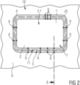
- Fig. 2 shows a schematic and explaining view of the window assembly 10 of Fig. 1 seen from outside which is installed in the body 8 of, for instance, a vehicle like a train.
- a number of inserts 6 or structural elements can be inserted with constant distance or step between each two neighboured inserts 6 as explained and shown in Fig. 2 on left and right sides of a perimeter or circumference of the window assembly 10. Further, inserts 6 may be arranged with variable distance or step as explained and shown in Fig. 2 on a lower side of the window assembly 10. As shown and explained in Fig. 2 , additional inserts 6 could be grouped, for instance, in a specific zone of the perimeter of the window assembly or glazing on an upper side of the window assembly 10.
Landscapes
- Engineering & Computer Science (AREA)
- Mechanical Engineering (AREA)
- Securing Of Glass Panes Or The Like (AREA)
- Window Of Vehicle (AREA)
Abstract
Description
- The present invention refers to a window assembly used, for instance, in a vehicle or building or, for instance, in a train or a car. More especially, the invention could be used, for instance, as a side window installed in a high-speed passenger-train.
- Lateral Cab and body side windows for high capacity means of transportation, for instance, buses, trains, and metro are designed for services in a wide range of environmental and operational conditions. Generally, such windows use a glazing, either a single pane laminated safety glass unit (LGU) or a double pane insulated glazing unit (IGU) connected to the main structural vehicle body by a metallic frame.
- The metallic frame is replaced increasingly by an extruded circumferential structural gasket that has structural properties in order to withstand defined static and dynamic loads caused by the operating conditions like, for instance, aerodynamic pressures, inertial forces due to acceleration or impacts/crashes, human loads and different combination of the mentioned actions in the spatial directions.
- The structural gasket presents significant advantages towards traditional solutions based on metallic frames coupling glazing and body structure. The main advantages of the structured gasket made of polymeric material are, for instance, the elimination of heavy and expensive parts like the metallic frame itself.
- The main problem of the structural gasket is related to the need of structural consistency of the gasket in transferring of comparable mechanical stress and loads from the glazing to the vehicle body structure and vice versa.
- Accordingly, it is an object of the invention to provide a window assembly avoiding the above mentioned problem, particularly, avoiding heavy and stiff structural gaskets in case of increased operational loads on windows.
- This object is solved by the window assembly of the invention as mentioned in
claim 1. Accordingly, the window assembly or window of the invention used, for instance, in a vehicle or building or, for instance, in a train or a car, particularly a side window for a high-speed passenger-train or a metro-train, comprises a glazing with one or more panes made of glass, plastic, and/or ceramic material, a window opening provided in a body of, for instance, a vehicle or building, a frame like gasket provided between the glazing and the body and holding the glazing on the body within the window opening and at least one insert for reinforcing the gasket. - The remarkable advantage of the invention is that, by using the reinforcing insert or inserts, the usual gaskets could be used even in the case of higher operational loads and stresses on the window.
- Further, since otherwise gaskets with increased stiffness would be required to withstand increased loads, the thicker and stiffer profiles of the gasket would not fit properly the curvature of the edge corners of the window. The heavy profiles of gasket could require often that these curved segments of the profiles have to be manufactured separately by injection and/or compression moulding processes resulting in a more complex and expansive gasket and window solution. Also these problems are avoided by the invention since the inserts enable to use small and sufficiently elastic profiles even in the case of higher operational loads.
- Further remarkable advantages of the window assembly of the present invention due to the inserts are lower weight than with standard solution, easier assembly and maintenance of the system glazing/gasket on the vehicle's body, better fitting on the subcomponents with improvement of the water tightness of the system and less design constraint due to a lighter profile of the gasket that is more elastic and, therefore, can fit better the curvature of the glazing, improved overall mechanical strength and fatigue performances
- Preferably, the window assembly of the invention provides a gasket holding the glazing on the body by receiving an opening edge face, faces or edge of the body of the vehicle or building and an glazing edge face, faces or edge of the glazing whereby at least one insert extends in the gasket to ensure a strong reinforcement of the gasket and, thus, also a reinforced mounting of the glazing on the body.
- The window assembly of the invention may have several inserts, pins or screws arranged along a perimeter or circumference of the gasket for improving the mechanical resistivity of the window assembly against increased mechanical loads effecting on the window assembly.
- The inserts or structural elements of the invention can be inserted with constant or variable step along the whole perimeter or alternatively on a specific zone of the glazing and/or the body of a vehicle or building, in order to be able to adapt the window assembly to the mechanical load acting on the window, particularly in the case of an uneven distribution of the mechanical loads acting on the window.
- The window assembly of the invention can comprise a circumferential body recess of the body of, for instance, a car or train, which is provided between parallel walls of the body, and an engaging portion of the gasket that extends between the walls within the body recess. The insert or the inserts then extend within the engaging portion of the gasket to provide an increased force for mounting the glazing on the body.
- The gasket of the invention can provide a gasket recess for accommodating and holding the glazing edge face or edge of the glazing to ensure the mounting of the glazing on the body together with the required water tightness of the window assembly.
- Preferably, the window assembly of the invention provides an even gasket bottom of the gasket, wherein a flanged head'of each of the inserts extending between the glazing edge face of the glazing and the gasket bottom of the gasket to ensure the mounting of the insert(s) on the gasket.
- Preferably, in the invention, an equalising layer or tape that can be adhesive is arranged between the glazing edge face and the flanged head of the insert to avoid any movement of the insert(s), for instance, in case of vibrations.
- The window assembly of the invention can have a lining layer, a lining tape or washer which is arranged between the flanged head of the insert(s) and the gasket bottom of the gasket recess to ensure a stable seat of the inserts on the gasket for reinforcing the gasket.
- Preferably, the window assembly of the invention provides an insert extending in a corresponding bore or hole of the gasket which is provided between the gasket bottom of the gasket recess and the engaging portion of the gasket to ensure a stable seat of the insert in the gasket for reinforcing thereof.
- The insert can have a tapered end portion extending in or fitting in a cavity or hollow space of the engaging portion of the gasket, whereby the cavity can be tapered correspondingly to the tapered end portion of the insert to provide a secured seat of the insert in the engaging portion of the gasket.
- Preferably, the circumferential gasket of the window assembly of the invention comprises an inner wall portion or inner web, an outer wall portion or outer web, and a middle portion, wherein the inner wall portion extends from an inner surface of the inner pane of the glazing to an inner body surface of the body, the outer wall portion of the gasket extends from an outer surface of the outer pane of the glazing to an outer body surface of the body and wherein the middle portion extends between the gasket bottom of the gasket and the opening edge face of the body and between the outer and inner wall portions of the gasket. This gasket provides a secure watertight seat of the glazing on the body.
- The window assembly of the invention can provide a bore or hole in the lining layer and a corresponding bore or hole in the middle portion from the gasket bottom of the gasket recess to the engaging portion of the gasket between the walls of the body, whereby the respective insert extends in the bore of the lining layer and in the corresponding bore of the middle portion of the gasket to ensure a secure seat of the insert in the gasket and, accordingly, a corresponding reinforcement of the gasket.
- Further advantageous embodiments of the invention are mentioned in the
dependent claims 2 to 15. Advantageous embodiments and advantages of the invention could also be derived from the following description of exemplified and preferred embodiments in connection with the drawings: - Fig. 1 a
- schematic section part-view of a window assembly according to a preferred and exemplified embodiment of the invention and seen in the direction of arrow I. in
Fig. 2 ; and - Fig. 2
- a schematic view of the window assembly of
Fig. 1 seen from outside which is installed in the body of, for instance, a vehicle like a train. -
Fig. 1 shows a schematic section part-view of awindow assembly 10 according to a preferred and exemplified embodiment of the invention wherein thewindow assembly 10 is shown in the assembled state with aglazing 1 mounted in a gasket 4 that extends on anopening edge face 5 or edge of abody 8, for instance, of a vehicle defining a window opening 7 as shown inFig. 2 . Thewindow assembly 10 could be used, for instance, as a side window of a high-speed passenger train. - The
glazing 1 of thewindow assembly 10 comprises, twoglass panes glazing edge face 11 or edge. Theglazing 1 is arranged within the window opening 7 of thebody 8. Theglazing 1 of thewindow assembly 10 may be an insulating glazing comprising, for instance, two usually transparent glass panes, anouter glass pane 2 and aninner glass pane 3. Accordingly, theglazing 1 is a double pane insulated glazing unit (IGU) coupled to and mounted on the mainstructural body 8 by the gasket 4. The outer andinner glass panes dehydrated gas gap 26 enclosing, for instance, air or a special inert gas. Theglass panes circumferential spacer 27 is arranged and glued in between the inner andouter glass panes circumferential sealant 28 is arranged between the outer andinner glass panes sealant 28 is flush to the outer andinner glass panes glazing edge face 11 of theglazing 1. Theouter glass pane 2 or theglazing 1 has an outer surface 2.1 directed to an outside of the corresponding vehicle or building. Theinner glass pane 3 or theglazing 1 has an inner surface 3.1 directed to an inside of the corresponding vehicle or building. - The
opening edge face 5 of thebody 8 is profiled and comprises a circumferential body recess 9 or holding fixture. Thebody recess 9 is defined by anouter wall 51 and aninner wall 52 extending in parallel wherein theouter wall 51 or thebody 8 has anouter body surface 53 directed to an environment of the vehicle or building and theinner wall 52 of thebody 8 has aninner body surface 54 directed to an inside of the vehicle or building. Thewalls opening edge face 5 of thebody 8. - The
window assembly 10 provides at least oneinsert 6 or several structural elements orinserts 6 in the form of preferably rotational symmetrical pins or screws for reinforcing the gasket 4, wherein therespective insert 6 extends substantially in the gasket 4. Eachinsert 6 comprises aflanged head 62, acylindrical portion 63, and a tapered end portion 61 wherein thecylindrical portion 63 extends between theflanged head 62 and the tapered end portion 61. Thecylindrical portion 63 of theinsert 6 or screw can be threaded to withstand increased loading conditions. If thecylindrical portion 63 is threaded, theinsert 6 can have a bushing fixed to alining layer 19. Theinsert 6 or inserts are made of composite materials, polymeric or plastic materials and/or preferably metallic materials, for instance, aluminum or stainless steel. - Further, the
window assembly 10 ofFig. 1 comprises a circumferential frame like structural gasket 4 provided between theglazing 1 and theopening edge face 5 or edge of thebody 8. The gasket 4 couples theglazing 1 to thebody 8 and it holds theglazing 1 within the window opening 7 on thebody 8 by holding theopening edge face 5 or edge of thebody 8 and theglazing edge face 11 or edge of theglazing 1. - The structural gasket 4 is a separate element made by extrusion or compression molding using polymeric material. The structural gasket 4 is duly fitted to the
glazing 1 and to thebody 8. The structural gasket 4 can be symmetrical or unsymmetrical in section. - The other function of the perimetral structural gasket 4 is to guarantee water tigtheness of the
window assembly 10 in the operational conditions and last but not least it provides the usual mandatory requirement of fire/smoke opacity and toxicity compliance, for instance, according to EN 45545. - The circumferential frame like structural gasket 4 of the
window assembly 10 comprises a circumferential gasket recess 14 for accommodating and holding the corresponding circumferentialglazing edge face 11 or edge of theglazing 1 wherein theglazing edge face 11 extends within thegasket recess 14 of the gasket 4. The gasket recess 14 of the gasket 4 provides acircumferential gasket bottom 15 that is opposed to theglazing edge face 11 or faces of theglazing 1. - The gasket 4 is made of a polymeric extruded or compression moulded material and it comprises structural elastic properties in order to withstand defined static and dynamic loads on the
window assembly 10 or window caused by the operating conditions like, for instance, aerodynamic uniformly distributed pressures up to 3kPa, inertial forces due to acceleration or impacts/crashes up to 5g, human loads and different combination of the mentioned actions in the spatial directions. - Further, the gasket 4 of the
window assembly 10 according to the invention ofFig. 1 comprises a circumferentialinner wall portion 23 or inner web, a circumferentialouter wall portion 24 or outer web, and amiddle portion 25. Theinner wall portion 23 extends from an inner surface 3.1 of theinner pane 3 of the insulatingglazing 1 to theinner body surface 54 of thebody 8 and presses against these surfaces 3.1 and 54. Theouter wall portion 24 of the gasket 4 extends from the outer surface 2.1 of theouter pane 2 of the insulatingglazing 1 to theouter body surface 53 of thebody 8 and it presses against these surfaces 2.1 and 53. Themiddle portion 25 extends between thegasket bottom 15 of thegasket recess 14 of the gasket 4 and the openingedge face 5 of thebody 8 and between the inner andouter wall portions - The gasket 4 comprises an engaging
portion 12 that extends between thewalls body 8 within thebody recess 9 of thebody 8 wherein the engagingportion 12 presses against inside surfaces of thewalls body 8. The engagingportion 12 may comprise one or moretapered cavities 22, three taperedcavities 22 are shown in the embodiment ofFig. 1 , surrounded by corresponding cavity walls 22.1. - Further, the gasket 4 has a number of
bores 20 corresponding to the number ofinserts 6 or pins. Each of thebores 20 is provided through themiddle portion 25 of the gasket 4 between thegasket bottom 15 of thegasket recess 14 and the engagingpotion 12 of the gasket 4. Accordingly, theinserts 6 or pins extend through themiddle portion 25 of the gasket 4 within thebores 20. Theinserts 6 extending within the engagingportion 12 of the gasket 4. The tapered end portion 21 of therespective insert 6 extends in a correspondingly taperedcircumferential cavity 22 or hollow space in the middle of the engagingportion 12 of the gasket 4. The tapered end portion 21 orinsert 6 may press against the cavity walls 22.1 of thecavity 22. - An equalising
layer 18 or tape is arranged between the glazing edge face 11 of theglazing 1 and theflanged head 62 of each of theinserts 6 or pins. The equalisinglayer 18 equalises a thickness of theflanged head 62 of thecorresponding insert 6. The equalisinglayer 18 may be adhesive. Further, alining layer 19, lining tape or washer is arranged between theflanged head 62 of each of theinserts 6 or pins and thegasket bottom 15 of thegasket recess 14 of the gasket 4. Thelining layer 19 may be polymeric and/or metallic. Thelining layer 19 has throughbores 30 or holes corresponding to thebores 20 of themiddle portion 25 of the gasket 4. Each of theinserts 6 extending through the corresponding bores 20 and 30 into the engagingportion 12 of the gasket 4. -
Fig. 2 shows a schematic and explaining view of thewindow assembly 10 ofFig. 1 seen from outside which is installed in thebody 8 of, for instance, a vehicle like a train. A number ofinserts 6 or structural elements can be inserted with constant distance or step between each two neighbouredinserts 6 as explained and shown inFig. 2 on left and right sides of a perimeter or circumference of thewindow assembly 10. Further, inserts 6 may be arranged with variable distance or step as explained and shown inFig. 2 on a lower side of thewindow assembly 10. As shown and explained inFig. 2 ,additional inserts 6 could be grouped, for instance, in a specific zone of the perimeter of the window assembly or glazing on an upper side of thewindow assembly 10.
Claims (15)
- Window assembly (10) for a vehicle or building, particularly a side window for a high-speed passenger-train, comprisinga glazing, (1) having one or more panes (2, 3) made of glass, plastic, and/or ceramic material, a window opening (7) provided in a body (8) of the vehicle or building,a frame like gasket (4) provided between the glazing (1) and the body (8) and holding the glazing (1) on the body (8) within the window' opening (7), andat least one insert (6) for reinforcing the gasket (4).
- Window assembly (10) according to claim 1, characterized in that:the glazing comprises a glazing edge face (11) or edge;the body (8) comprises: an opening edge face (5) defining the window opening (7) provided in the body (8);the gasket (4) holds the glazing (1) on the body (8) by receiving the opening edge face (5) of the body (8) and the glazing edge face (11) or edge of the glazing (1); andthe at least one insert (6) extends in the gasket (4).
- Window assembly (10) according to claim 1, characterized by several inserts (6) or pins arranged along a perimeter or circumference of the gasket (4).
- Window assembly (10) according to claim 3, characterized in that the opening edge face (5) of the body (8) is profiled and comprises a circumferential body recess (9) for an engaging portion (12) of the gasket (4).
- Window assembly (10) according to claim 4, characterized in that the body recess (9) of the body (8) is provided between parallel walls (51, 52) of the body (8) and
that the engaging portion (12) of the gasket (4) extends between the walls (51, 52) within the body recess (9), the insert (s) (6) extending within the engaging portion (12) of the gasket (4). - Window assembly (10) according to one of the preceding claims, characterized in that the gasket (4) comprises a gasket recess (14) for accommodating and holding the glazing edge face (11) or edge of the glazing (1).
- Window assembly (10) according to claim 6, characterized in that the gasket recess (14) of the gasket (4) provides a circumferential gasket bottom (15), the insert(s) or pin(s) comprising each a flanged head (62) extending between the glazing edge face (11) and the gasket bottom (15) of the gasket recess (14).
- Window assembly (10) according to claim 7, characterized in that an equalising layer (18) or tape is arranged between the glazing edge face (11) and the flanged head (62) of the insert (6) or pin.
- Window assembly (10) according to claim 7 or claim 8, characterized in that a lining layer (13), lining tape or washer is arranged between the flanged head (62) of the insert(s) (6) or pin(s) and the gasket bottom (15) of the gasket recess (14).
- Window assembly (10) according to one of the claims 6 to 9, characterized in that the insert (6) extends in a corresponding bore (20) of the gasket (4) provided between the gasket bottom (15) of the gasket recess (14) and the engaging portion (12) of the gasket (4).
- Window assembly (10) according to one of the claims 4 to 10, characterized in that the insert (6) comprises a tapered end portion (61) extending in a correspondingly cavity (22) or hollow space of the engaging portion (12) of the gasket (4).
- Window assembly (10) according to one of the preceding claims, characterized in that the glazing (1) is an insulating glazing comprising two glass panes (2, 3).
- Window assembly (10) according to claim 12, characterized in that the circumferential gasket (4) comprises an inner wall portion (23) or inner web, an outer wall portion (24) or outer web, and a middle portion (25), wherein the inner wall portion (23) extends from an inner surface (3.1) of the inner pane (3) of the insulating glazing (1) to an inner body surface (53) of the body (8), the outer wall portion (24) of the gasket (4) extends from an outer surface (2.1) of the outer pane (2) of the insulating glazing (1) to an outer body surface (53) of the body (8), and wherein the middle portion (25) extends between the gasket bottom (15) of the gasket recess (14) of the gasket (4) and the opening edge face (5) of the body (8) and between the outer and inner wall portions (24, 23) of the gasket (4).
- Window assembly (10) according to claim 13, characterized in that a bore (30) or hole in a lining layer (19) and a corresponding bore (20) or hole in the middle portion (25) from the gasket bottom (15) of the gasket recess (14) to the engaging portion (12) of the gasket (4) between the walls (51, 52) of the body (8) are provided, wherein the respective insert (6) extends in the bore (30) of the lining layer (19) and in the corresponding bore (20) of the middle portion (25) of the gasket(4).
- Window assembly (10) according to one of the preceding claims, characterized in that the inserts 6 or structural elements are inserted with constant or variable step along the whole perimeter of the window assembly (10) or on a specific zone of the glazing (1) and/or of the body (8) of a vehicle or building.
Priority Applications (4)
| Application Number | Priority Date | Filing Date | Title |
|---|---|---|---|
| EP22425004.3A EP4227123B1 (en) | 2022-02-10 | 2022-02-10 | Window assembly |
| ES22425004T ES3053068T3 (en) | 2022-02-10 | 2022-02-10 | Window assembly |
| PL22425004.3T PL4227123T3 (en) | 2022-02-10 | 2022-02-10 | WINDOW UNIT |
| PCT/EP2023/025055 WO2023151866A1 (en) | 2022-02-10 | 2023-02-07 | Window assembly |
Applications Claiming Priority (1)
| Application Number | Priority Date | Filing Date | Title |
|---|---|---|---|
| EP22425004.3A EP4227123B1 (en) | 2022-02-10 | 2022-02-10 | Window assembly |
Publications (3)
| Publication Number | Publication Date |
|---|---|
| EP4227123A1 true EP4227123A1 (en) | 2023-08-16 |
| EP4227123B1 EP4227123B1 (en) | 2025-06-25 |
| EP4227123C0 EP4227123C0 (en) | 2025-06-25 |
Family
ID=81326298
Family Applications (1)
| Application Number | Title | Priority Date | Filing Date |
|---|---|---|---|
| EP22425004.3A Active EP4227123B1 (en) | 2022-02-10 | 2022-02-10 | Window assembly |
Country Status (4)
| Country | Link |
|---|---|
| EP (1) | EP4227123B1 (en) |
| ES (1) | ES3053068T3 (en) |
| PL (1) | PL4227123T3 (en) |
| WO (1) | WO2023151866A1 (en) |
Citations (4)
| Publication number | Priority date | Publication date | Assignee | Title |
|---|---|---|---|---|
| US2138374A (en) * | 1938-01-18 | 1938-11-29 | Om Edwards Co Inc | Window construction |
| US4591203A (en) * | 1984-04-02 | 1986-05-27 | General Motors Corporation | Modular window assembly |
| US5809707A (en) * | 1996-10-04 | 1998-09-22 | Bargados; Vince | Window guard and replacement system for vehicle windows |
| CN109178002A (en) * | 2018-08-29 | 2019-01-11 | 中车青岛四方机车车辆股份有限公司 | Forms mounting structure and rail vehicle with it |
-
2022
- 2022-02-10 PL PL22425004.3T patent/PL4227123T3/en unknown
- 2022-02-10 ES ES22425004T patent/ES3053068T3/en active Active
- 2022-02-10 EP EP22425004.3A patent/EP4227123B1/en active Active
-
2023
- 2023-02-07 WO PCT/EP2023/025055 patent/WO2023151866A1/en not_active Ceased
Patent Citations (4)
| Publication number | Priority date | Publication date | Assignee | Title |
|---|---|---|---|---|
| US2138374A (en) * | 1938-01-18 | 1938-11-29 | Om Edwards Co Inc | Window construction |
| US4591203A (en) * | 1984-04-02 | 1986-05-27 | General Motors Corporation | Modular window assembly |
| US5809707A (en) * | 1996-10-04 | 1998-09-22 | Bargados; Vince | Window guard and replacement system for vehicle windows |
| CN109178002A (en) * | 2018-08-29 | 2019-01-11 | 中车青岛四方机车车辆股份有限公司 | Forms mounting structure and rail vehicle with it |
Also Published As
| Publication number | Publication date |
|---|---|
| PL4227123T3 (en) | 2025-10-27 |
| EP4227123B1 (en) | 2025-06-25 |
| EP4227123C0 (en) | 2025-06-25 |
| ES3053068T3 (en) | 2026-01-19 |
| WO2023151866A1 (en) | 2023-08-17 |
Similar Documents
| Publication | Publication Date | Title |
|---|---|---|
| US8544798B2 (en) | Window replacement for filling a window frame | |
| EP2238022B1 (en) | Optimized aircraft manhole | |
| US8523110B2 (en) | Door frame component of cast titanium and structural fuselage part | |
| EP3392114B1 (en) | Vehicle door for railway vehicle and railway vehicle comprising the vehicle door | |
| KR101080709B1 (en) | Curtain wall system with combination of aluminum frame and steel structure | |
| US20220010609A1 (en) | Frame assembly | |
| CN104583520A (en) | Integrated window pane and window which comprises such a pane | |
| EP4227123B1 (en) | Window assembly | |
| JPH0662057B2 (en) | Vehicle window | |
| CN105073548B (en) | Door leaf for vehicle | |
| US20040161585A1 (en) | Aircraft structural components | |
| US7367741B2 (en) | Connector element for a glass post and beam construction | |
| KR102650145B1 (en) | A glazing unit, especially for aircraft, that allows the receiving opening to be blocked in the event of damage. | |
| CN121516219A (en) | Asymmetrically connected acrylic laminate windshield | |
| EP4227124A1 (en) | Window assembly | |
| KR20050027062A (en) | Method of fitting flush glazing | |
| JP2008138484A (en) | Multi-layer glass support structure | |
| US20250162289A1 (en) | Glazed assembly for an aircraft, method for manufacturing such a glazed assembly and aircraft comprising such a glazed assembly | |
| US4777772A (en) | Externally insulated window mounting | |
| EP1353816B1 (en) | Method for installing a fixed window and a fixed window | |
| CN216690776U (en) | Carved heat-insulation aluminum profile | |
| CN111891159B (en) | Vehicle window structure | |
| JP6620030B2 (en) | Side door window mounting structure for railway vehicles | |
| JP2000343939A (en) | Vehicle window structure and vehicle window mounting structure | |
| CN214365805U (en) | Built-in type frame structure rolling door fixing section bar |
Legal Events
| Date | Code | Title | Description |
|---|---|---|---|
| PUAI | Public reference made under article 153(3) epc to a published international application that has entered the european phase |
Free format text: ORIGINAL CODE: 0009012 |
|
| STAA | Information on the status of an ep patent application or granted ep patent |
Free format text: STATUS: THE APPLICATION HAS BEEN PUBLISHED |
|
| AK | Designated contracting states |
Kind code of ref document: A1 Designated state(s): AL AT BE BG CH CY CZ DE DK EE ES FI FR GB GR HR HU IE IS IT LI LT LU LV MC MK MT NL NO PL PT RO RS SE SI SK SM TR |
|
| STAA | Information on the status of an ep patent application or granted ep patent |
Free format text: STATUS: REQUEST FOR EXAMINATION WAS MADE |
|
| 17P | Request for examination filed |
Effective date: 20231109 |
|
| RBV | Designated contracting states (corrected) |
Designated state(s): AL AT BE BG CH CY CZ DE DK EE ES FI FR GB GR HR HU IE IS IT LI LT LU LV MC MK MT NL NO PL PT RO RS SE SI SK SM TR |
|
| GRAP | Despatch of communication of intention to grant a patent |
Free format text: ORIGINAL CODE: EPIDOSNIGR1 |
|
| STAA | Information on the status of an ep patent application or granted ep patent |
Free format text: STATUS: GRANT OF PATENT IS INTENDED |
|
| INTG | Intention to grant announced |
Effective date: 20250328 |
|
| GRAS | Grant fee paid |
Free format text: ORIGINAL CODE: EPIDOSNIGR3 |
|
| GRAA | (expected) grant |
Free format text: ORIGINAL CODE: 0009210 |
|
| STAA | Information on the status of an ep patent application or granted ep patent |
Free format text: STATUS: THE PATENT HAS BEEN GRANTED |
|
| AK | Designated contracting states |
Kind code of ref document: B1 Designated state(s): AL AT BE BG CH CY CZ DE DK EE ES FI FR GB GR HR HU IE IS IT LI LT LU LV MC MK MT NL NO PL PT RO RS SE SI SK SM TR |
|
| REG | Reference to a national code |
Ref country code: GB Ref legal event code: FG4D |
|
| REG | Reference to a national code |
Ref country code: CH Ref legal event code: EP |
|
| REG | Reference to a national code |
Ref country code: DE Ref legal event code: R096 Ref document number: 602022016406 Country of ref document: DE |
|
| REG | Reference to a national code |
Ref country code: CH Ref legal event code: EP |
|
| REG | Reference to a national code |
Ref country code: IE Ref legal event code: FG4D |
|
| U01 | Request for unitary effect filed |
Effective date: 20250725 |
|
| U07 | Unitary effect registered |
Designated state(s): AT BE BG DE DK EE FI FR IT LT LU LV MT NL PT RO SE SI Effective date: 20250806 |
|
| PG25 | Lapsed in a contracting state [announced via postgrant information from national office to epo] |
Ref country code: NO Free format text: LAPSE BECAUSE OF FAILURE TO SUBMIT A TRANSLATION OF THE DESCRIPTION OR TO PAY THE FEE WITHIN THE PRESCRIBED TIME-LIMIT Effective date: 20250925 Ref country code: GR Free format text: LAPSE BECAUSE OF FAILURE TO SUBMIT A TRANSLATION OF THE DESCRIPTION OR TO PAY THE FEE WITHIN THE PRESCRIBED TIME-LIMIT Effective date: 20250926 |
|
| PG25 | Lapsed in a contracting state [announced via postgrant information from national office to epo] |
Ref country code: HR Free format text: LAPSE BECAUSE OF FAILURE TO SUBMIT A TRANSLATION OF THE DESCRIPTION OR TO PAY THE FEE WITHIN THE PRESCRIBED TIME-LIMIT Effective date: 20250625 |
|
| PG25 | Lapsed in a contracting state [announced via postgrant information from national office to epo] |
Ref country code: RS Free format text: LAPSE BECAUSE OF FAILURE TO SUBMIT A TRANSLATION OF THE DESCRIPTION OR TO PAY THE FEE WITHIN THE PRESCRIBED TIME-LIMIT Effective date: 20250925 |
|
| PG25 | Lapsed in a contracting state [announced via postgrant information from national office to epo] |
Ref country code: IS Free format text: LAPSE BECAUSE OF FAILURE TO SUBMIT A TRANSLATION OF THE DESCRIPTION OR TO PAY THE FEE WITHIN THE PRESCRIBED TIME-LIMIT Effective date: 20251025 |
|
| PG25 | Lapsed in a contracting state [announced via postgrant information from national office to epo] |
Ref country code: SM Free format text: LAPSE BECAUSE OF FAILURE TO SUBMIT A TRANSLATION OF THE DESCRIPTION OR TO PAY THE FEE WITHIN THE PRESCRIBED TIME-LIMIT Effective date: 20250625 |
|
| REG | Reference to a national code |
Ref country code: ES Ref legal event code: FG2A Ref document number: 3053068 Country of ref document: ES Kind code of ref document: T3 Effective date: 20260119 |
|
| PG25 | Lapsed in a contracting state [announced via postgrant information from national office to epo] |
Ref country code: CZ Free format text: LAPSE BECAUSE OF FAILURE TO SUBMIT A TRANSLATION OF THE DESCRIPTION OR TO PAY THE FEE WITHIN THE PRESCRIBED TIME-LIMIT Effective date: 20250625 |
|
| PG25 | Lapsed in a contracting state [announced via postgrant information from national office to epo] |
Ref country code: SK Free format text: LAPSE BECAUSE OF FAILURE TO SUBMIT A TRANSLATION OF THE DESCRIPTION OR TO PAY THE FEE WITHIN THE PRESCRIBED TIME-LIMIT Effective date: 20250625 |
|
| U20 | Renewal fee for the european patent with unitary effect paid |
Year of fee payment: 5 Effective date: 20260220 |
|
| PGFP | Annual fee paid to national office [announced via postgrant information from national office to epo] |
Ref country code: GB Payment date: 20260324 Year of fee payment: 5 |
|
| PGFP | Annual fee paid to national office [announced via postgrant information from national office to epo] |
Ref country code: ES Payment date: 20260319 Year of fee payment: 5 |
|
| PGFP | Annual fee paid to national office [announced via postgrant information from national office to epo] |
Ref country code: PL Payment date: 20260225 Year of fee payment: 5 |
|
| PLBE | No opposition filed within time limit |
Free format text: ORIGINAL CODE: 0009261 |
|
| STAA | Information on the status of an ep patent application or granted ep patent |
Free format text: STATUS: NO OPPOSITION FILED WITHIN TIME LIMIT |
|
| REG | Reference to a national code |
Ref country code: CH Ref legal event code: L10 Free format text: ST27 STATUS EVENT CODE: U-0-0-L10-L00 (AS PROVIDED BY THE NATIONAL OFFICE) Effective date: 20260507 |
|
| 26N | No opposition filed |
Effective date: 20260326 |