EP4227039B1 - Concrete grinder and concrete grinding apparatus - Google Patents
Concrete grinder and concrete grinding apparatus Download PDFInfo
- Publication number
- EP4227039B1 EP4227039B1 EP22212447.1A EP22212447A EP4227039B1 EP 4227039 B1 EP4227039 B1 EP 4227039B1 EP 22212447 A EP22212447 A EP 22212447A EP 4227039 B1 EP4227039 B1 EP 4227039B1
- Authority
- EP
- European Patent Office
- Prior art keywords
- mounting
- drive
- drive ring
- ring
- concrete
- Prior art date
- Legal status (The legal status is an assumption and is not a legal conclusion. Google has not performed a legal analysis and makes no representation as to the accuracy of the status listed.)
- Active
Links
Images



Classifications
-
- B—PERFORMING OPERATIONS; TRANSPORTING
- B24—GRINDING; POLISHING
- B24B—MACHINES, DEVICES, OR PROCESSES FOR GRINDING OR POLISHING; DRESSING OR CONDITIONING OF ABRADING SURFACES; FEEDING OF GRINDING, POLISHING, OR LAPPING AGENTS
- B24B7/00—Machines or devices designed for grinding plane surfaces on work, including polishing plane glass surfaces; Accessories therefor
- B24B7/10—Single-purpose machines or devices
- B24B7/18—Single-purpose machines or devices for grinding floorings, walls, ceilings or the like
- B24B7/186—Single-purpose machines or devices for grinding floorings, walls, ceilings or the like with disc-type tools
-
- B—PERFORMING OPERATIONS; TRANSPORTING
- B24—GRINDING; POLISHING
- B24B—MACHINES, DEVICES, OR PROCESSES FOR GRINDING OR POLISHING; DRESSING OR CONDITIONING OF ABRADING SURFACES; FEEDING OF GRINDING, POLISHING, OR LAPPING AGENTS
- B24B55/00—Safety devices for grinding or polishing machines; Accessories fitted to grinding or polishing machines for keeping tools or parts of the machine in good working condition
- B24B55/04—Protective covers for the grinding wheel
- B24B55/05—Protective covers for the grinding wheel specially designed for portable grinding machines
- B24B55/052—Protective covers for the grinding wheel specially designed for portable grinding machines with rotating tools
-
- B—PERFORMING OPERATIONS; TRANSPORTING
- B24—GRINDING; POLISHING
- B24B—MACHINES, DEVICES, OR PROCESSES FOR GRINDING OR POLISHING; DRESSING OR CONDITIONING OF ABRADING SURFACES; FEEDING OF GRINDING, POLISHING, OR LAPPING AGENTS
- B24B7/00—Machines or devices designed for grinding plane surfaces on work, including polishing plane glass surfaces; Accessories therefor
- B24B7/20—Machines or devices designed for grinding plane surfaces on work, including polishing plane glass surfaces; Accessories therefor characterised by a special design with respect to properties of the material of non-metallic articles to be ground
- B24B7/22—Machines or devices designed for grinding plane surfaces on work, including polishing plane glass surfaces; Accessories therefor characterised by a special design with respect to properties of the material of non-metallic articles to be ground for grinding inorganic material, e.g. stone, ceramics, porcelain
Definitions
- the invention relates to the technical field of concrete grinding equipment, in particular to a concrete grinder and a concrete grinding apparatus.
- a concrete grinder is a common specialized tool in the field of building finishing and decoration, which is mainly used to grind and polish the rough surfaces of concrete, cement pavements, cast-in-place floors, walls and the like. Due to the unevenness of the surfaces, they need to be ground by concrete grinders.
- a concrete grinder comprises a main body, wherein a grinding disk is rotatably connected with the main body, a dust-proof cover is mounted on the outer wall of the main body, the dust-proof cover is a brush ring or a rubber ring, and the lower surface of the dust-proof cover is flush with that of the grinding disk which is positioned within the dust-proof cover.
- the dust-proof cover is synchronously pressed against the ground, so that the dust-proof cover blocks gravels or dust to reduce pollution in the working environment when the grinding disk works on the ground.
- DE 89 14 346 U1 relates to a motorized tool that can be driven into a rotational movement for removing material from a surface, and which has a tool opening and can be connected to a suction device on a transportable drive unit.
- the suction device contains slots which simultaneously extend in the longitudinal and circumferential directions.
- the tool comprises a protective wall, which comprises holes for screws that are simultaneously received and guided in the corresponding slots in the suction device for longitudinal adjustment of the suction device.
- EP 2 186 600 A1 discloses a grinder having a drive shaft mounted in a gear neck, and a concrete grinding wheel detachably attached at the drive shaft and provided with a funnel-shaped extraction hood that covers the concrete grinding wheel.
- the extraction hood is fastened in the region of a central opening of the gear neck by a holding device.
- the holding device has a height adjustment device with which the extraction hood is height-adjustably directly or indirectly guided and fixed in an axial direction of the drive shaft with respect to the gear neck.
- the invention provides a concrete grinder and a concrete grinding apparatus so as to improve the precision of the concrete grinder.
- the invention provides a concrete grinder, which adopts the following technical scheme:
- a concrete grinder comprising a main body, wherein a grinding disk is rotatably connected with the lower end of the main body, a drive ring is coaxially connected with the outer wall of the main body, the drive ring and the grinding disk are coaxially mounted, a dust-proof cover is coaxially mounted at the lower end of the drive ring, a plurality of drive blocks are disposed on the outer wall of the main body, a plurality of drive grooves for sliding the drive blocks are formed on the inner wall of the drive ring, the drive grooves are in one-to-one correspondence with the drive blocks, one end of the drive grooves is upward while the other end is downward, and the drive ring is equipped with an adjusting assembly for locking the position of the drive ring.
- the adjusting assembly when the grinding disk is worn, the adjusting assembly is opened and the drive ring is pushed, so that the drive blocks slide in the drive grooves, the drive ring drives the dust-proof cover to move in the extending direction of the drive grooves and the dust-proof cover moves along the axial direction of the drive ring.
- the adjusting assembly is closed to lock the position of the drive ring and the position of the dust-proof cover is readjusted, whereby the deformation of the dust-proof cover is reduced, the main body and the grinding disk are less likely to incline and the precision of the concrete grinder is improved.
- the adjusting assembly comprises a mounting base and a mounting band, wherein the mounting base is disposed on the outer wall of the drive ring, a retractable cavity is formed inside the mounting base, the mounting band passes through the mounting base and fits tightly around the outer wall of the drive ring, both ends of the mounting band are positioned in the retractable cavity, an adjusting bolt is disposed in the retractable cavity, an adjusting threaded hole for threaded connection of the adjusting bolt is formed on the wall of the retractable cavity, the adjusting threaded hole penetrates the outer wall of the mounting base, one end of the adjusting bolt protrudes out of the mounting base and is connected with a force-applying member, and at least one deformable groove is formed on the drive ring.
- the force-applying member is rotated to drive the adjusting bolt to rotate, so that the adjusting bolt rotates around its own axis, moves in the adjusting threaded hole, and pulls two ends of the mounting band to tighten the mounting band inside the retractable cavity. Then the mounting band tightens the drive ring and the deformable grooves facilitate deformation, so that the inner wall of the drive ring presses against the outer wall of the main body, thereby completing the locking of the drive ring.
- all the drive grooves extend in an inclined manner and are inclined in the circumferential direction of the drive ring.
- the drive ring presses against the main body and is not likely to rotate, so that the drive ring is less likely to move and the stability of the drive ring is improved.
- an anti-drop ring and a limiting boss are coaxially disposed on the outer wall of the drive ring, and the two ends of the mounting band along the axial direction of the drive ring respectively press against the anti-drop ring and the limiting boss.
- the mounting band is positioned between the anti-drop ring and the limiting boss, so that the mounting band is not likely to separate from the drive ring and the stability of the mounting band can be improved.
- the limiting boss is positioned at one end of the drive ring close to the ground, a socket for mounting the dust-proof cover is coaxially formed on the limiting boss, a mounting ring is mounted on the outer wall of the end of the dust-proof cover away from the ground, mounting bolts are connected in a threaded manner to the end of the limiting boss facing the ground” and an abutment head for pressing the mounting ring against the socket is disposed on the mounting bolts.
- the dust-proof cover when the dust-proof cover needs to be mounted, the dust-proof cover is pushed to be insert into the socket. Then the mounting ring is inserted into the socket, and the mounting bolts are all screwed so as to be in threaded connection with the limiting boss until the abutment heads are pressed against the mounting ring, so that the dust-proof cover is not likely to separate from the drive ring and is user-friendly in terms of mounting and operation.
- a plurality of stiffeners are disposed on the wall of the socket.
- the formation of the socket is not likely to influence the integral strength of the drive ring, and the integral strength of the drive ring is improved instead.
- the invention provides a concrete grinding apparatus, which adopts the following technical scheme:
- a concrete grinding apparatus comprising a concrete grinder and a bracket connected thereto, wherein at least two sliding wheels are mounted at the bottom of the bracket, the bracket is equipped with a mounting frame extending horizontally, the mounting frame is equipped with limiting members, a lifting plate having limiting grooves is disposed on the main body, the limiting members are inserted in the limiting grooves in a sliding manner, the extending direction of the limiting grooves is the same as the axial direction of the drive ring, the mounting frame is in threaded connection with a locking bolt which is used for pressing the lifting plate against the mounting frame, and the axial direction of the locking bolt is perpendicular to the extending direction of the limiting grooves.
- the main body is mounted on the mounting frame, wherein the bracket is pushed and the sliding wheels are turned, so that the concrete grinder can be operated in a user-friendly way.
- the dust-proof cover is adjusted by taking the above steps to allow the lower surface of the dust-proof cover to be flush with the lower surface of the grinding disk, the locking bolt is screwed so as not to press against the lifting plate, the main body is pulled to drive the lifting plate to move, the limiting members slide in the limiting grooves until the grinding disk is flush with and presses against the ground, and the locking bolt presses the lifting plate against the mounting frame, so that the main body is lifted or lowered, thus making it easy to operate the concrete grinder and improving the precision of the concrete grinder.
- the mounting frame is equipped with a supporting wheel for pressing against the ground.
- the stability of the bracket is improved, wherein the concrete grinder is not likely to incline even if it is pressed forward and downward in the actual grinding process, so that the operation of the grinding disk is not prone to be affected and the precision of the concrete grinder is improved.
- the mounting frame is in threaded connection with an anti-drop bolt, the axial direction of the anti-drop bolt is the same as the extending direction of the limiting grooves, and the lower end of the anti-drop bolt presses against the upper surface of the lifting plate.
- the anti-drop bolt when the main body has been lifted or lowered, the anti-drop bolt is screwed so as to move on the mounting frame until the anti-drop bolt is pressed against the lifting plate, wherein the main body and the lifting plate are not likely to move upward even if the concrete grinder is pressed forward and downward in the actual grinding process, so that the precision of the concrete grinder is improved.
- the supporting wheel comprises a supporting base and a wheel body, wherein the wheel body is rotatably connected to the supporting base, a lifting threaded rod is rotatably connected to the supporting base, and the lifting threaded rod is in threaded connection with the mounting frame.
- the lifting threaded rod when the supporting wheel is ready to be mounted, the lifting threaded rod is rotated so as to be in threaded connection with the mounting frame, and the lifting threaded rod is rotated so that the height of the supporting wheel is easy to adjust and the mounting frame is kept in a horizontal state.
- the embodiments of the invention disclose a concrete grinder.
- a concrete grinder comprising a main body 1, wherein a grinding disk 11 is rotatably connected to the lower surface of the main body 1, the grinding disk 11 and the main body 1 have a common axis, and the lower cross-section of the body 1 is circular according the embodiments of the invention.
- a drive ring 2 is rotatably fitted around the outer wall of the main body 1, the drive ring 2 and the grinding disk 11 have a common axis, a plurality of drive blocks 22 are fixed to the outer wall of the main body 1, three drive blocks 22 are adopted in the embodiments of the invention, three drive grooves 21 are formed on the inner wall of the drive ring 2, the drive grooves 21 are in one-to-one correspondence with the drive blocks 22, and the drive grooves 21 extend along the outer wall of the drive ring 2.
- One end of the drive grooves 21 starts from the upper surface of the drive ring 2 while the other end of the drive grooves 21 is close to the lower end of the drive ring 2, and all the drive grooves 21 extend in the same direction.
- An adjusting assembly 3 is mounted around the drive ring 2 for locking the position of the drive ring 2
- a dust-proof cover 23 is coaxially mounted at the lower surface of the drive ring 2
- the grinding disk 11 is positioned within the dust-proof cover 23.
- all the drive grooves 21 extend obliquely in the circumferential direction of the drive ring 2.
- the adjusting assembly 3 When the grinding disk 11 is worn, the adjusting assembly 3 is opened, the drive ring 2 is turned around its own axis, and the drive blocks 22 slide in the drive grooves 21. Then the drive ring 2 moves along its own axis and forces the dust-proof cover 23 to move, and the adjusting assembly 3 is closed when the lower surface of the dust-proof cover 23 is flush with that of the grinding disk 11, thereby completing the adjustment of the dust-proof cover 23. Therefore, in the above process, additional pressure applied to the main body 1 is reduced, so that the main body 1 and the grinding disk 11 are not prone to incline under the pressure, thus preventing the grinding precision of the grinding disk 11 from being affected and improving the operating precision of the concrete grinder.
- inclined drive grooves 21 stabilize the drive ring 2 more than vertical drive grooves 21, wherein the positions of the drive ring 2 and the dust-proof cover 23 can be locked only by limiting the movement of the drive ring 2 along its own axis, thereby preventing the drive ring 2 from moving the dust-proof cover 23 along its own axis in normal conditions.
- the adjusting assembly 3 comprises a mounting base 31, a mounting band 32, an adjusting bolt 33 and a force-applying member 34.
- the mounting base 31 is fixed to the outer wall of the drive ring 2, and a retractable cavity 35 is formed inside the mounting base 31, wherein the retractable cavity 35 extends along the diameter of the drive ring 2, and a through groove 36 which passes through the outer wall of the mounting base 31 is formed in each of the two opposite walls of the retractable cavity 35.
- the mounting band 32 is tightly fitted around the drive ring 2, wherein the inner wall of the mounting band 32 is pressed against the outer wall of the drive ring 2, and both ends of the mounting band 32 pass through the through grooves 36 and extend into the retractable cavity 35.
- the adjusting bolt 33 passes through the front and the rear ends of the mounting band 32, which are stacked with each other, and a mounting block 37 is disposed on the adjusting bolt 33, which is used for pressing the mounting band 32 against the head of the adjusting bolt 33.
- An adjusting threaded hole 38 which penetrates the wall of the retractable cavity 35 is formed on the outer wall of the mounting base 31, wherein the adjusting threaded hole 38 extends along the radial direction of the drive ring 2 and the adjusting bolt 33 is in threaded connection to the adjusting threaded hole 38.
- One end of the adjusting bolt 33 protrudes out of the mounting base 31 through the adjusting threaded hole 38, and the force-applying member 34 is fixed to the said end of the adjusting bolt 33.
- Three deformable grooves 39 are formed on the inner wall of the drive ring 2, which pass through the outer wall of the drive ring 2 and extend along the axial direction of the drive ring 2.
- the force-applying member 34 is turned to rotate the adjusting bolt 33 around its own axis, the adjusting bolt 33 works threadedly with the adjusting threaded hole 38 to move the adjusting bolt 33 away from the drive ring 2.
- both ends of the mounting band 32 are strained by the adjusting bolt 33, so that the mounting band 32 which passes through the through grooves 36 draws towards the inside of the retractable cavity 35 and tightens the outer wall of the drive ring 2, whereby the deformable grooves 39 are deformed to bring the two opposite walls of the deformable grooves 39 closer to each other.
- the inner wall of the drive ring 2 is tightly pressed against the outer wall of the main body 1, so that the drive ring 2 is not prone to rotate around its own axis and to move.
- the outer wall of the drive ring 2 is coaxially connected with an anti-drop ring 4 and a limiting boss 5, wherein the anti-drop ring 4 is positioned above the limiting boss 5, the mounting band 32 is positioned between the anti-drop ring 4 and the limiting boss 5, and the anti-drop ring 4 and the limiting boss 5 are fitted respectively against the upper and lower ends of the mounting band 32, so that the mounting band 32 is not prone to separate from the drive ring 2, thereby increasing the stability of the mounting band 32 and improving the clamping effect of the mounting band 32 on the drive ring 2 as well.
- deformable grooves 39 also extend through the anti-drop ring 4, so that the anti-drop ring 4 is less likely to influence the deformation of the drive ring 2.
- the lower surface of the limiting boss 5 is flush with that of the drive ring 2, and a socket 51 is formed on both the lower surfaces of the limiting boss 5 and the drive ring 2, wherein the socket 51 is ring-shaped and shares the axis with the drive ring 2.
- a mounting ring 52 is coaxially fixed to the outer wall at the upper end of the dust-proof cover 23, which is fitted into the socket 51 together with the mounting ring 52.
- a plurality of mounting threaded holes 53 are formed on the lower surface of the limiting boss 5, and mounting bolts 54 are connected into the mounting threaded holes 53 in a threaded manner, wherein the mounting bolts 54 are circumferentially positioned around the axis of the drive ring 2 as the center, the mounting bolts 54 and the drive ring 2 have a common axial direction, and the bolt head of the mounting bolts 54 is an abutment head 55.
- a plurality of stiffeners 56 are fixed onto the wall of the socket 51, which are circumferentially positioned around the axis of the drive ring 2, and the two ends of the stiffener 56 are respectively connected to the two opposite walls of the socket 51, so as to enhance the overall strength of the drive ring 2, wherein the presence of the socket 51 is not likely to affect the overall strength of the drive ring 2.
- the principle of embodying a concrete grinder is as follows: when the grinding disk 11 is worn, firstly, the force-applying member 34 is loosened to rotate the adjusting bolt 33 around its own axis which is threadedly connected inside the adjusting threaded hole 38, thereby enabling the adjusting bolt 33 to move the two ends of the mounting band 32 towards the drive ring 2 and loosening the mounting band 32. So far, the deformable grooves 39 return to the natural status, and the force-applying member 34 is pulled to drive the adjusting bolt 33, the mounting band 32 and the drive ring 2 to rotate around the axis of the drive ring 2. Then the drive blocks 22 slide in the drive grooves 21, so that the drive ring 2 drives the dust-proof cover 23 to move along the axial direction of the drive ring 2 due to the obliqueness of the drive grooves 21.
- the force-applying member 34 is tightened to move the adjusting bolt 33 in a direction away from the drive ring 2 and to draw the mounting band 32 which passes through the through groove 36 towards the inside of the retractable cavity 35, so that the outer wall of the drive ring 2 is tightened to deform the deformable grooves 39 and the inner wall of the drive ring is pressed against the outer wall of the main body 1, thereby completing the locking of the drive ring 2.
- the embodiments of the invention also disclose a concrete grinding apparatus.
- a concrete grinding apparatus comprising a concrete grinder defined in the above embodiments and a bracket 6 connected thereto, wherein the bracket 6 is vertically mounted, two sliding wheels 61 are mounted at the bottom of the bracket 6, a mounting frame 7 which comprises two parallel mounting rods 71 is fixed to the bracket 6 and extends horizontally, a connecting rod 72 connects the two mounting rods 71 to form an "H" shape between the mounting rods 71 and the connecting rod 72 in the embodiments, and the main body 1 is mounted between the two mounting rods 71.
- the two opposite sides of the main body 1 respectively correspond to the two mounting rods 71, and the main body 1 is bolted to lifting plates 8 comprising a horizontal plate 81 in a horizontal state and a vertical plate 82 in a vertical state, wherein the horizontal plate 81 is connected with the main body and the vertical plate 82 is positioned at the side of one mounting rod 71 far away from the other mounting rod 71, the mounting rod 71 is bolted with a placement member 9 which is equipped with two limiting members 91 integrally, the vertical plate 82 is fitted adjacent to the placement member 9, and two limiting grooves 83 are vertically formed on the vertical plate 82.
- the mounting rod 71 is connected horizontally to a locking bolt 101 in a threaded manner which passes through the placement member 9, and a sliding groove 84 is formed on the vertical plate 82 and is positioned between the two limiting grooves 83.
- the upper surface of the mounting rod 71 is equipped with an anti-drop threaded hole 711 penetrating the lower surface of the mounting rod 71, and the anti-drop threaded hole is internally connected with an anti-drop bolt 102 in a threaded manner, wherein the anti-drop bolt 102 is vertically mounted and the lower surface of the anti-drop bolt 102 presses against the upper surface of the horizontal plate 81.
- a supporting wheel 103 comprising a supporting base 104 and a wheel body 105 is mounted on the lower end of the connecting rod 72 , wherein the wheel body 105 is rotatably connected to the supporting base 104, the upper end of the supporting base 104 is rotatably connected to a lifting threaded rod 106 which is vertically mounted, and the lifting threaded rod 106 is in threaded connection with the connecting rod 72, thereby making it convenient for workers to mount the supporting wheel 103 on the connecting rod 72.
- the lifting threaded rod 106 is rotated to force the supporting base 104 to move in a vertical direction, which makes it convenient to adjust the horizontal height of the supporting wheel 103, so that the bracket 6 and the mounting frame 7 are kept stable.
- the supporting wheel 103 is positioned between the two sliding wheels 61 to form a triangle, and in the actual grinding process, even if the concrete grinder is pressed downward and forward, it is not likely to incline and to influence the operation of the grinding disk 11, thereby further improving the precision of the concrete grinder.
- the principle of embodying a concrete grinding apparatus is as follows: after the grinding disk 11 is worn and separates from the ground, the above procedure is taken to adjust the dust-proof cover 23, and the locking bolt 101 is then unscrewed so that the bolt head of the locking bolt 101 moves away from the vertical plate 82. Then the main body 1 is moved downward to press the grinding disk 11 against the ground. And then the limiting members 91 slide in the limiting grooves 83, and the locking bolt 101 slides in the sliding groove 84.
- the locking bolt 101 is tightened so as to be in threaded connection with the mounting rod 71 and to press against the vertical plate 82, and the vertical plate 82 is pressed tightly on the mounting rod 71, thereby completing the adjustment of the position of the main body 1, making it convenient for workers to push the bracket 6 to operate the concrete grinder horizontally on the ground and improving the precision of the concrete grinder.
- the anti-drop bolt 102 is rotated so as to move inside the anti-drop threaded hole 711 until the lower end of the anti-drop bolt 102 presses against the upper surface of the horizontal plate 81, so that in the actual grinding process the anti-drop bolt 102 presses against the main body 1 and the lifting plate 8 to prevent them from shifting upward even if the concrete grinder is pressed downward and forward, thereby further improving the precision of the concrete grinder.
Landscapes
- Engineering & Computer Science (AREA)
- Mechanical Engineering (AREA)
- Chemical & Material Sciences (AREA)
- Ceramic Engineering (AREA)
- Inorganic Chemistry (AREA)
- Grinding-Machine Dressing And Accessory Apparatuses (AREA)
- Finish Polishing, Edge Sharpening, And Grinding By Specific Grinding Devices (AREA)
Description
- The invention relates to the technical field of concrete grinding equipment, in particular to a concrete grinder and a concrete grinding apparatus.
- A concrete grinder is a common specialized tool in the field of building finishing and decoration, which is mainly used to grind and polish the rough surfaces of concrete, cement pavements, cast-in-place floors, walls and the like. Due to the unevenness of the surfaces, they need to be ground by concrete grinders.
- According to the related technology, a concrete grinder comprises a main body, wherein a grinding disk is rotatably connected with the main body, a dust-proof cover is mounted on the outer wall of the main body, the dust-proof cover is a brush ring or a rubber ring, and the lower surface of the dust-proof cover is flush with that of the grinding disk which is positioned within the dust-proof cover. When the grinding disk is pressed against the ground, the dust-proof cover is synchronously pressed against the ground, so that the dust-proof cover blocks gravels or dust to reduce pollution in the working environment when the grinding disk works on the ground.
- However, in the grinding process of a concrete grinder, it is necessary to keep the lower surface of the grinding disk parallel to the ground, and the grinding disk of the concrete grinder is prone to wear after running for a certain period of time so that the lower surface of the grinding disk is not flush with that of the dust-proof cover. Workers need to press and put pressure on the main body to press the lower surface of the dust-proof cover against the ground and to even deform the dust-proof cover, so that the grinding disk can be pressed against the ground. In the above process, due to the different degrees of the pressure by the two hands, the main body and the grinding disk can be easily inclined, thus affecting the precision of the concrete grinder.
-
DE 89 14 346 U1 relates to a motorized tool that can be driven into a rotational movement for removing material from a surface, and which has a tool opening and can be connected to a suction device on a transportable drive unit. The suction device contains slots which simultaneously extend in the longitudinal and circumferential directions. The tool comprises a protective wall, which comprises holes for screws that are simultaneously received and guided in the corresponding slots in the suction device for longitudinal adjustment of the suction device. -
EP 2 186 600 A1 - The invention is set out in the appended set of claims.
- The invention provides a concrete grinder and a concrete grinding apparatus so as to improve the precision of the concrete grinder.
- In a first aspect, the invention provides a concrete grinder, which adopts the following technical scheme:
- A concrete grinder, comprising a main body, wherein a grinding disk is rotatably connected with the lower end of the main body, a drive ring is coaxially connected with the outer wall of the main body, the drive ring and the grinding disk are coaxially mounted, a dust-proof cover is coaxially mounted at the lower end of the drive ring, a plurality of drive blocks are disposed on the outer wall of the main body, a plurality of drive grooves for sliding the drive blocks are formed on the inner wall of the drive ring, the drive grooves are in one-to-one correspondence with the drive blocks, one end of the drive grooves is upward while the other end is downward, and the drive ring is equipped with an adjusting assembly for locking the position of the drive ring.
- According to the above technical scheme, when the grinding disk is worn, the adjusting assembly is opened and the drive ring is pushed, so that the drive blocks slide in the drive grooves, the drive ring drives the dust-proof cover to move in the extending direction of the drive grooves and the dust-proof cover moves along the axial direction of the drive ring. When the lower surface of the dust-proof cover is flush with that of the grinding disk, the adjusting assembly is closed to lock the position of the drive ring and the position of the dust-proof cover is readjusted, whereby the deformation of the dust-proof cover is reduced, the main body and the grinding disk are less likely to incline and the precision of the concrete grinder is improved.
- Optionally, the adjusting assembly comprises a mounting base and a mounting band, wherein the mounting base is disposed on the outer wall of the drive ring, a retractable cavity is formed inside the mounting base, the mounting band passes through the mounting base and fits tightly around the outer wall of the drive ring, both ends of the mounting band are positioned in the retractable cavity, an adjusting bolt is disposed in the retractable cavity, an adjusting threaded hole for threaded connection of the adjusting bolt is formed on the wall of the retractable cavity, the adjusting threaded hole penetrates the outer wall of the mounting base, one end of the adjusting bolt protrudes out of the mounting base and is connected with a force-applying member, and at least one deformable groove is formed on the drive ring.
- According to the above technical scheme, when the drive ring needs to be locked, the force-applying member is rotated to drive the adjusting bolt to rotate, so that the adjusting bolt rotates around its own axis, moves in the adjusting threaded hole, and pulls two ends of the mounting band to tighten the mounting band inside the retractable cavity. Then the mounting band tightens the drive ring and the deformable grooves facilitate deformation, so that the inner wall of the drive ring presses against the outer wall of the main body, thereby completing the locking of the drive ring.
- Optionally, all the drive grooves extend in an inclined manner and are inclined in the circumferential direction of the drive ring.
- According to the above technical scheme, when the mounting band is tightened, the drive ring presses against the main body and is not likely to rotate, so that the drive ring is less likely to move and the stability of the drive ring is improved.
- Optionally, an anti-drop ring and a limiting boss are coaxially disposed on the outer wall of the drive ring, and the two ends of the mounting band along the axial direction of the drive ring respectively press against the anti-drop ring and the limiting boss.
- According to the above technical scheme, the mounting band is positioned between the anti-drop ring and the limiting boss, so that the mounting band is not likely to separate from the drive ring and the stability of the mounting band can be improved.
- Optionally, the limiting boss is positioned at one end of the drive ring close to the ground, a socket for mounting the dust-proof cover is coaxially formed on the limiting boss, a mounting ring is mounted on the outer wall of the end of the dust-proof cover away from the ground, mounting bolts are connected in a threaded manner to the end of the limiting boss facing the ground" and an abutment head for pressing the mounting ring against the socket is disposed on the mounting bolts.
- According to the above technical scheme, when the dust-proof cover needs to be mounted, the dust-proof cover is pushed to be insert into the socket. Then the mounting ring is inserted into the socket, and the mounting bolts are all screwed so as to be in threaded connection with the limiting boss until the abutment heads are pressed against the mounting ring, so that the dust-proof cover is not likely to separate from the drive ring and is user-friendly in terms of mounting and operation.
- Optionally, a plurality of stiffeners are disposed on the wall of the socket.
- According to the above technical scheme, the formation of the socket is not likely to influence the integral strength of the drive ring, and the integral strength of the drive ring is improved instead.
- In a second aspect, the invention provides a concrete grinding apparatus, which adopts the following technical scheme:
- A concrete grinding apparatus, comprising a concrete grinder and a bracket connected thereto, wherein at least two sliding wheels are mounted at the bottom of the bracket, the bracket is equipped with a mounting frame extending horizontally, the mounting frame is equipped with limiting members, a lifting plate having limiting grooves is disposed on the main body, the limiting members are inserted in the limiting grooves in a sliding manner, the extending direction of the limiting grooves is the same as the axial direction of the drive ring, the mounting frame is in threaded connection with a locking bolt which is used for pressing the lifting plate against the mounting frame, and the axial direction of the locking bolt is perpendicular to the extending direction of the limiting grooves.
- According to the above technical scheme, the main body is mounted on the mounting frame, wherein the bracket is pushed and the sliding wheels are turned, so that the concrete grinder can be operated in a user-friendly way.
- When the grinding disk is worn, the dust-proof cover is adjusted by taking the above steps to allow the lower surface of the dust-proof cover to be flush with the lower surface of the grinding disk, the locking bolt is screwed so as not to press against the lifting plate, the main body is pulled to drive the lifting plate to move, the limiting members slide in the limiting grooves until the grinding disk is flush with and presses against the ground, and the locking bolt presses the lifting plate against the mounting frame, so that the main body is lifted or lowered, thus making it easy to operate the concrete grinder and improving the precision of the concrete grinder.
- Optionally, the mounting frame is equipped with a supporting wheel for pressing against the ground.
- According to the above technical scheme, the stability of the bracket is improved, wherein the concrete grinder is not likely to incline even if it is pressed forward and downward in the actual grinding process, so that the operation of the grinding disk is not prone to be affected and the precision of the concrete grinder is improved.
- Optionally, the mounting frame is in threaded connection with an anti-drop bolt, the axial direction of the anti-drop bolt is the same as the extending direction of the limiting grooves, and the lower end of the anti-drop bolt presses against the upper surface of the lifting plate.
- According to the above technical scheme, when the main body has been lifted or lowered, the anti-drop bolt is screwed so as to move on the mounting frame until the anti-drop bolt is pressed against the lifting plate, wherein the main body and the lifting plate are not likely to move upward even if the concrete grinder is pressed forward and downward in the actual grinding process, so that the precision of the concrete grinder is improved.
- Optionally, the supporting wheel comprises a supporting base and a wheel body, wherein the wheel body is rotatably connected to the supporting base, a lifting threaded rod is rotatably connected to the supporting base, and the lifting threaded rod is in threaded connection with the mounting frame.
- According to the above technical scheme, when the supporting wheel is ready to be mounted, the lifting threaded rod is rotated so as to be in threaded connection with the mounting frame, and the lifting threaded rod is rotated so that the height of the supporting wheel is easy to adjust and the mounting frame is kept in a horizontal state.
- In conclusion, the present invention has the following beneficial effects:
- 1. With the presence of the main body, the grinding disk, the drive ring, the dust-proof cover, the drive blocks, the drive grooves and the adjusting assembly, the position of the dust-proof cover is easy to readjust, so that the deformation of the dust-proofing cover is reduced when it is pressed, thereby preventing the main body and the grinding disk from inclining and improving the precision of the concrete grinder;
- 2. With the presence of the anti-drop ring and the limiting boss, the stability of the mounting band is improved;
- 3. With the presence of the socket, the mounting ring, the mounting bolts and the abutment heads, the dust-proof cover is easy to mount;
- 4. With the presence of the stiffeners, the stability of the drive ring is improved;
- 5. With the presence of the bracket, the sliding wheels, the mounting frame, the limiting members, the lifting plate, the limiting grooves and the locking bolt, the concrete grinder is easy to operate and the precision of the concrete grinder is improved;
- 6. With the presence of the supporting wheel, the precision of the concrete grinder is improved;
- 7. With the presence of the anti-drop bolt, the stability of the main body is improved and the precision of the concrete grinder is further improved;
- 8. With the presence of the lifting threaded rod, the supporting wheel is easy to mount and adjust.
-
-
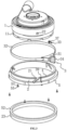
FIG. 1 is a schematic diagram of the overall structure of the embodiments of the present invention; -
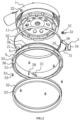
FIG. 2 is an exploded view of the whole concrete grinder in the embodiments of the present invention; -
FIG. 3 is an exploded view of the drive grooves, the drive blocks, the drive ring and the deformable grooves in the embodiments of the present invention; -
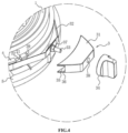
FIG. 4 is an exploded view of the adjusting assembly in the embodiments of the present invention; -
FIG. 5 is an exploded view of the lifting plate, the placement member, the anti-drop bolt, and the locking bolt in the embodiments of the present invention; -
FIG. 6 is a schematic diagram of the structure of the supporting wheel in the embodiments of the present invention. - Reference numerals: 1. main body; 11. grinding disk; 2. drive ring; 21. drive groove; 22. drive block; 23. dust-proof cover; 3. adjusting assembly; 31. mounting base; 32. mounting band; 33. adjusting bolt; 34. force-applying member; 35. retractable cavity; 36. through groove; 37. mounting block; 38. adjusting threaded hole; 39. deformable groove; 4. anti-drop ring; 5. limiting boss; 51. socket; 52. mounting ring; 53. mounting threaded hole; 54. mounting bolt; 55. abutment head; 56. stiffener; 6. bracket; 61. sliding wheel; 7. mounting frame; 71. mounting rod; 711. anti-drop threaded hole; 72. connecting rod; 8. lifting plate; 81. horizontal plate; 82. vertical plate; 83. limiting groove; 84. sliding groove; 9. placement member; 91. limiting member; 101. locking bolt; 102. anti-drop bolt; 103. supporting wheel; 104. supporting base; 105. wheel body; 106. lifting threaded rod.
- The present invention is described in further detail below with reference to
FIGS. 1-6 . - The embodiments of the invention disclose a concrete grinder.
- As shown in
FIGS. 1 and2 , a concrete grinder, comprising a main body 1, wherein a grindingdisk 11 is rotatably connected to the lower surface of the main body 1, the grindingdisk 11 and the main body 1 have a common axis, and the lower cross-section of the body 1 is circular according the embodiments of the invention. Adrive ring 2 is rotatably fitted around the outer wall of the main body 1, thedrive ring 2 and the grindingdisk 11 have a common axis, a plurality of drive blocks 22 are fixed to the outer wall of the main body 1, three drive blocks 22 are adopted in the embodiments of the invention, three drivegrooves 21 are formed on the inner wall of thedrive ring 2, thedrive grooves 21 are in one-to-one correspondence with the drive blocks 22, and thedrive grooves 21 extend along the outer wall of thedrive ring 2. - One end of the
drive grooves 21 starts from the upper surface of thedrive ring 2 while the other end of thedrive grooves 21 is close to the lower end of thedrive ring 2, and all thedrive grooves 21 extend in the same direction. An adjustingassembly 3 is mounted around thedrive ring 2 for locking the position of thedrive ring 2, a dust-proof cover 23 is coaxially mounted at the lower surface of thedrive ring 2, and the grindingdisk 11 is positioned within the dust-proof cover 23. - As shown in
FIGS. 2 and3 , all thedrive grooves 21 extend obliquely in the circumferential direction of thedrive ring 2. - When the grinding
disk 11 is worn, the adjustingassembly 3 is opened, thedrive ring 2 is turned around its own axis, and the drive blocks 22 slide in thedrive grooves 21. Then thedrive ring 2 moves along its own axis and forces the dust-proof cover 23 to move, and the adjustingassembly 3 is closed when the lower surface of the dust-proof cover 23 is flush with that of the grindingdisk 11, thereby completing the adjustment of the dust-proof cover 23. Therefore, in the above process, additional pressure applied to the main body 1 is reduced, so that the main body 1 and the grindingdisk 11 are not prone to incline under the pressure, thus preventing the grinding precision of the grindingdisk 11 from being affected and improving the operating precision of the concrete grinder. - It should be noted that
inclined drive grooves 21 stabilize thedrive ring 2 more thanvertical drive grooves 21, wherein the positions of thedrive ring 2 and the dust-proof cover 23 can be locked only by limiting the movement of thedrive ring 2 along its own axis, thereby preventing thedrive ring 2 from moving the dust-proof cover 23 along its own axis in normal conditions. - As shown in
FIGS. 3 and4 , the adjustingassembly 3 comprises a mountingbase 31, a mountingband 32, an adjustingbolt 33 and a force-applyingmember 34. - The mounting
base 31 is fixed to the outer wall of thedrive ring 2, and aretractable cavity 35 is formed inside the mountingbase 31, wherein theretractable cavity 35 extends along the diameter of thedrive ring 2, and a throughgroove 36 which passes through the outer wall of the mountingbase 31 is formed in each of the two opposite walls of theretractable cavity 35. - The mounting
band 32 is tightly fitted around thedrive ring 2, wherein the inner wall of the mountingband 32 is pressed against the outer wall of thedrive ring 2, and both ends of the mountingband 32 pass through the throughgrooves 36 and extend into theretractable cavity 35. - The adjusting
bolt 33 passes through the front and the rear ends of the mountingband 32, which are stacked with each other, and a mountingblock 37 is disposed on the adjustingbolt 33, which is used for pressing the mountingband 32 against the head of the adjustingbolt 33. - An adjusting threaded
hole 38 which penetrates the wall of theretractable cavity 35 is formed on the outer wall of the mountingbase 31, wherein the adjusting threadedhole 38 extends along the radial direction of thedrive ring 2 and the adjustingbolt 33 is in threaded connection to the adjusting threadedhole 38. - One end of the adjusting
bolt 33 protrudes out of the mountingbase 31 through the adjusting threadedhole 38, and the force-applyingmember 34 is fixed to the said end of the adjustingbolt 33. - Three
deformable grooves 39 are formed on the inner wall of thedrive ring 2, which pass through the outer wall of thedrive ring 2 and extend along the axial direction of thedrive ring 2. - When the
drive ring 2 needs to be locked, the force-applyingmember 34 is turned to rotate the adjustingbolt 33 around its own axis, the adjustingbolt 33 works threadedly with the adjusting threadedhole 38 to move the adjustingbolt 33 away from thedrive ring 2. Then both ends of the mountingband 32 are strained by the adjustingbolt 33, so that the mountingband 32 which passes through the throughgrooves 36 draws towards the inside of theretractable cavity 35 and tightens the outer wall of thedrive ring 2, whereby thedeformable grooves 39 are deformed to bring the two opposite walls of thedeformable grooves 39 closer to each other. Then the inner wall of thedrive ring 2 is tightly pressed against the outer wall of the main body 1, so that thedrive ring 2 is not prone to rotate around its own axis and to move. - Similarly, when the
drive ring 2 needs to be unlocked, only the force-applyingmember 34 needs to be rotated to loosen the mountingband 32, thus simplifying the unlocking process. In the meantime, after the unlocking is completed, the force-applyingmember 34 is pulled to rotate the adjustingbolt 33, the mountingbase 31 and thedrive ring 2 around the axis of thedrive ring 2, thereby enabling the rotation of thedrive ring 2. Workers can complete the adjusting process with only one hand, which is user-friendly for them. - The outer wall of the
drive ring 2 is coaxially connected with ananti-drop ring 4 and a limitingboss 5, wherein theanti-drop ring 4 is positioned above the limitingboss 5, the mountingband 32 is positioned between theanti-drop ring 4 and the limitingboss 5, and theanti-drop ring 4 and the limitingboss 5 are fitted respectively against the upper and lower ends of the mountingband 32, so that the mountingband 32 is not prone to separate from thedrive ring 2, thereby increasing the stability of the mountingband 32 and improving the clamping effect of the mountingband 32 on thedrive ring 2 as well. - It should be noted that the
deformable grooves 39 also extend through theanti-drop ring 4, so that theanti-drop ring 4 is less likely to influence the deformation of thedrive ring 2. - As shown in
FIGS. 2 and3 , the lower surface of the limitingboss 5 is flush with that of thedrive ring 2, and asocket 51 is formed on both the lower surfaces of the limitingboss 5 and thedrive ring 2, wherein thesocket 51 is ring-shaped and shares the axis with thedrive ring 2. A mountingring 52 is coaxially fixed to the outer wall at the upper end of the dust-proof cover 23, which is fitted into thesocket 51 together with the mountingring 52. A plurality of mounting threadedholes 53 are formed on the lower surface of the limitingboss 5, and mountingbolts 54 are connected into the mounting threadedholes 53 in a threaded manner, wherein the mountingbolts 54 are circumferentially positioned around the axis of thedrive ring 2 as the center, the mountingbolts 54 and thedrive ring 2 have a common axial direction, and the bolt head of the mountingbolts 54 is anabutment head 55. - When the dust-
proof cover 23 drives the mountingring 52 into thesocket 51, all the mountingbolts 54 are screwed to be connected with the mounting threadedholes 53 in a threaded way until the abutment heads 55 of the mountingbolts 54 are pressed against the lower surface of the mountingring 52, so that the mountingring 52 is pressed tightly against the inside of thesocket 51, thereby completing the installation of the dust-proof cover 23. It is convenient for workers to make installation or replacement. - A plurality of
stiffeners 56 are fixed onto the wall of thesocket 51, which are circumferentially positioned around the axis of thedrive ring 2, and the two ends of thestiffener 56 are respectively connected to the two opposite walls of thesocket 51, so as to enhance the overall strength of thedrive ring 2, wherein the presence of thesocket 51 is not likely to affect the overall strength of thedrive ring 2. - According to the embodiment of the invention, the principle of embodying a concrete grinder is as follows: when the grinding
disk 11 is worn, firstly, the force-applyingmember 34 is loosened to rotate the adjustingbolt 33 around its own axis which is threadedly connected inside the adjusting threadedhole 38, thereby enabling the adjustingbolt 33 to move the two ends of the mountingband 32 towards thedrive ring 2 and loosening the mountingband 32. So far, thedeformable grooves 39 return to the natural status, and the force-applyingmember 34 is pulled to drive the adjustingbolt 33, the mountingband 32 and thedrive ring 2 to rotate around the axis of thedrive ring 2. Then the drive blocks 22 slide in thedrive grooves 21, so that thedrive ring 2 drives the dust-proof cover 23 to move along the axial direction of thedrive ring 2 due to the obliqueness of thedrive grooves 21. - Then, after the lower surface of the dust-
proof cover 23 is flush with that of the grindingdisk 11, the force-applyingmember 34 is tightened to move the adjustingbolt 33 in a direction away from thedrive ring 2 and to draw the mountingband 32 which passes through the throughgroove 36 towards the inside of theretractable cavity 35, so that the outer wall of thedrive ring 2 is tightened to deform thedeformable grooves 39 and the inner wall of the drive ring is pressed against the outer wall of the main body 1, thereby completing the locking of thedrive ring 2. - According to the above procedure, additional pressure applied to the main body 1 is reduced in the process of adjusting the height of the dust-
proof cover 23, so that the main body 1 and the grindingdisk 11 are not likely to incline and the precision of the concrete grinder can be improved. - The embodiments of the invention also disclose a concrete grinding apparatus.
- As shown in
FIGS. 1 and5 , a concrete grinding apparatus, comprising a concrete grinder defined in the above embodiments and abracket 6 connected thereto, wherein thebracket 6 is vertically mounted, two slidingwheels 61 are mounted at the bottom of thebracket 6, a mountingframe 7 which comprises twoparallel mounting rods 71 is fixed to thebracket 6 and extends horizontally, a connectingrod 72 connects the two mountingrods 71 to form an "H" shape between the mountingrods 71 and the connectingrod 72 in the embodiments, and the main body 1 is mounted between the two mountingrods 71. - The two opposite sides of the main body 1 respectively correspond to the two mounting
rods 71, and the main body 1 is bolted to liftingplates 8 comprising ahorizontal plate 81 in a horizontal state and avertical plate 82 in a vertical state, wherein thehorizontal plate 81 is connected with the main body and thevertical plate 82 is positioned at the side of one mountingrod 71 far away from the other mountingrod 71, the mountingrod 71 is bolted with a placement member 9 which is equipped with two limitingmembers 91 integrally, thevertical plate 82 is fitted adjacent to the placement member 9, and two limitinggrooves 83 are vertically formed on thevertical plate 82. - The mounting
rod 71 is connected horizontally to alocking bolt 101 in a threaded manner which passes through the placement member 9, and a slidinggroove 84 is formed on thevertical plate 82 and is positioned between the two limitinggrooves 83. - The upper surface of the mounting
rod 71 is equipped with an anti-drop threaded hole 711 penetrating the lower surface of the mountingrod 71, and the anti-drop threaded hole is internally connected with ananti-drop bolt 102 in a threaded manner, wherein theanti-drop bolt 102 is vertically mounted and the lower surface of theanti-drop bolt 102 presses against the upper surface of thehorizontal plate 81. - As shown in
FIGS. 1 and6 , a supportingwheel 103 comprising a supportingbase 104 and awheel body 105 is mounted on the lower end of the connectingrod 72 , wherein thewheel body 105 is rotatably connected to the supportingbase 104, the upper end of the supportingbase 104 is rotatably connected to a lifting threadedrod 106 which is vertically mounted, and the lifting threadedrod 106 is in threaded connection with the connectingrod 72, thereby making it convenient for workers to mount the supportingwheel 103 on the connectingrod 72. - In the meantime, after the supporting
wheel 103 is mounted, the lifting threadedrod 106 is rotated to force the supportingbase 104 to move in a vertical direction, which makes it convenient to adjust the horizontal height of the supportingwheel 103, so that thebracket 6 and the mountingframe 7 are kept stable. The supportingwheel 103 is positioned between the two slidingwheels 61 to form a triangle, and in the actual grinding process, even if the concrete grinder is pressed downward and forward, it is not likely to incline and to influence the operation of the grindingdisk 11, thereby further improving the precision of the concrete grinder. - According to the embodiments of the invention, the principle of embodying a concrete grinding apparatus is as follows: after the grinding
disk 11 is worn and separates from the ground, the above procedure is taken to adjust the dust-proof cover 23, and thelocking bolt 101 is then unscrewed so that the bolt head of thelocking bolt 101 moves away from thevertical plate 82. Then the main body 1 is moved downward to press the grindingdisk 11 against the ground. And then the limitingmembers 91 slide in the limitinggrooves 83, and thelocking bolt 101 slides in the slidinggroove 84. - After the position of the main body 1 is locked, the locking
bolt 101 is tightened so as to be in threaded connection with the mountingrod 71 and to press against thevertical plate 82, and thevertical plate 82 is pressed tightly on the mountingrod 71, thereby completing the adjustment of the position of the main body 1, making it convenient for workers to push thebracket 6 to operate the concrete grinder horizontally on the ground and improving the precision of the concrete grinder. - In the meantime, after the vertical height of the main body 1 is adjusted, the
anti-drop bolt 102 is rotated so as to move inside the anti-drop threaded hole 711 until the lower end of theanti-drop bolt 102 presses against the upper surface of thehorizontal plate 81, so that in the actual grinding process theanti-drop bolt 102 presses against the main body 1 and thelifting plate 8 to prevent them from shifting upward even if the concrete grinder is pressed downward and forward, thereby further improving the precision of the concrete grinder. - The foregoing are all preferred embodiments of the present invention, which are not intended to limit the scope of protection of the present invention. Therefore, all equivalent changes made according to the structure, shape, and principle of the invention shall be included in the scope of protection of the invention.
Claims (10)
- A concrete grinder, comprising a main body (1), wherein the lower end of the main body (1) is rotatably connected with a grinding disk (11), the outer wall of the main body is rotatably connected with a drive ring (2), the drive ring (2) and the grinding disk (11) are coaxially mounted, a plurality of drive grooves (21) are formed on the inner wall of the drive ring (2), one end of the drive grooves (21) is upward while the other end is downward, and the drive ring (2) is equipped with an adjusting assembly (3) for locking the position of the drive ring (2),
characterized by further comprising:a dust-proof cover (23) coaxially mounted at the lower end of the drive ring, anda plurality of drive blocks (22) disposed on the outer wall of the main body (1),wherein the plurality of drive grooves (21) is adapted for sliding the drive blocks (22), the drive grooves (21) are in one-to-one correspondence with the drive blocks (22). - The concrete grinder of claim 1, wherein the adjusting assembly (3) comprises a mounting base (31) and a mounting band (32), the mounting base (31) is mounted on the outer wall of the drive ring (2), a retractable cavity (35) is formed in the mounting base, the mounting band (32) passes through the mounting base (31) and fits tightly against the outer wall of the drive ring (2), both ends of the mounting band (32) are positioned in the retractable cavity (35), an adjusting bolt (33) is mounted in the retractable cavity (35), both ends of the mounting band (32) are disposed on the adjusting bolt (33), an adjusting threaded hole (38) for the threaded connection of the adjusting bolt (33) is formed on the wall of the retractable cavity (35), the adjusting threaded hole (38) passes through the outer wall of the mounting base (31), one end of the adjusting bolt (33) protrudes out of the mounting base (31) and is connected with a force-applying member (34), and at least one deformable groove (39) is formed on the drive ring (2).
- The concrete grinder of claim 2, wherein all the drive grooves (21) extend in an inclined manner and are inclined to the same side around the circumferential direction of the drive ring (2).
- The concrete grinder of claim 3, wherein an anti-drop ring (4) and a limiting boss (5) coaxially are mounted on the outer wall of the drive ring (2), and the two ends of the mounting band (32) are respectively pressed against the anti-drop ring (4) and the limiting boss (5) along the axial direction of the drive ring (2).
- The concrete grinder of claim 4, wherein the limiting boss (5) is disposed at the end of the drive ring (2) close to the ground, a socket (51) for inserting the dust-proof cover (23) is coaxially formed on the limiting boss (5), and a mounting ring (52) is mounted on the outer wall of the end of the dust-proof cover (23) far away from the ground, mounting bolts (54) are in threaded connection with the end of the limiting boss (5) facing the ground, and an abutment head (55) for pressing the mounting ring (52) against the socket (51) is disposed on the mounting bolts (54).
- The concrete grinder of claim 5, wherein a plurality of stiffeners (56) are disposed on the wall of the socket (51).
- A concrete grinding apparatus, comprising a concrete grinder of any one of claims 1-6, and a bracket (6) connected thereto, wherein at least two sliding wheels (61) are mounted at the bottom of the bracket (6), a mounting frame (7) with a horizontal extending is mounted on the bracket (7), limiting members (91) are mounted on the mounting frame (7), a lifting plate (8) is mounted on the main body (1), limiting grooves (83) are formed on the lifting plate (8), the limiting members (91) are inserted in the limiting grooves (83) in a sliding manner, the extending directions of the limiting grooves (83) are the same as the axial direction of the drive ring (2), the mounting frame (7) is in threaded connection with a locking bolt (101) used for pressing the lifting plate (8) against the mounting frame (7), and the axial direction of the locking bolt (101) is perpendicular to the extending direction of the limiting grooves (83).
- The concrete grinding apparatus of claim 7, wherein the mounting frame (7) is equipped with a supporting wheel (103) for pressing against the ground.
- The concrete grinding apparatus of claim 7, wherein the mounting frame (7) is in threaded connection with an anti-drop bolt (102), the axial direction of the anti-drop bolt (102) is the same as the extending direction of the limiting grooves (83), and the lower end of the anti-drop bolt is pressed against the upper surface of the lifting plate (8).
- The concrete grinding apparatus of claim 8, wherein the supporting wheel (103) comprises a supporting base (104) and a wheel body (105), the wheel body (105) is rotatably connected to the supporting base (104), a lifting threaded rod (106) is rotatably connected to the supporting base (102), and the lifting threaded rod (106) is in threaded connection with the mounting frame (7).
Applications Claiming Priority (1)
| Application Number | Priority Date | Filing Date | Title |
|---|---|---|---|
| CN202210062697.XA CN114346792B (en) | 2022-01-19 | 2022-01-19 | Rough polishing machine and rough polishing device |
Publications (4)
| Publication Number | Publication Date |
|---|---|
| EP4227039A2 EP4227039A2 (en) | 2023-08-16 |
| EP4227039A3 EP4227039A3 (en) | 2023-10-18 |
| EP4227039B1 true EP4227039B1 (en) | 2024-08-07 |
| EP4227039C0 EP4227039C0 (en) | 2024-08-07 |
Family
ID=81090446
Family Applications (1)
| Application Number | Title | Priority Date | Filing Date |
|---|---|---|---|
| EP22212447.1A Active EP4227039B1 (en) | 2022-01-19 | 2022-12-09 | Concrete grinder and concrete grinding apparatus |
Country Status (2)
| Country | Link |
|---|---|
| EP (1) | EP4227039B1 (en) |
| CN (1) | CN114346792B (en) |
Families Citing this family (2)
| Publication number | Priority date | Publication date | Assignee | Title |
|---|---|---|---|---|
| CN119526162B (en) * | 2025-01-21 | 2025-05-06 | 中建五局(烟台)建设工程有限公司 | A grinding device for large-area epoxy floor construction |
| CN120439145B (en) * | 2025-07-10 | 2025-11-04 | 福建兴翼智能装备股份有限公司 | A quick-release grinding head grinding machine and its working method |
Family Cites Families (8)
| Publication number | Priority date | Publication date | Assignee | Title |
|---|---|---|---|---|
| DE8914346U1 (en) * | 1989-12-06 | 1990-01-25 | Festo AG & Co, 73734 Esslingen | Tool that can be driven by a motor to produce a rotary movement |
| EP2186600B1 (en) * | 2008-11-12 | 2011-11-02 | Collomix Rühr-und Mischgeräte GmbH | Surface grinder, especially concrete grinder |
| CN101776301A (en) * | 2010-02-09 | 2010-07-14 | 浙江工业大学 | Spiral ascending mechanism for side-suction type environment-friendly stove |
| JP7033972B2 (en) * | 2018-03-20 | 2022-03-11 | 株式会社東京精密 | Polishing equipment |
| CN211890280U (en) * | 2019-12-19 | 2020-11-10 | 深圳市永鑫达电子塑胶有限公司 | Dustproof polishing machine |
| CN212444446U (en) * | 2020-06-23 | 2021-02-02 | 刘金杨 | A wall grinding device |
| CN214351350U (en) * | 2021-02-07 | 2021-10-08 | 上海麟瑞建筑工程有限公司 | Grinding machine |
| CN214723149U (en) * | 2021-03-31 | 2021-11-16 | 河南华中建筑设计院有限公司 | Wall grinding device for construction with dust absorption function |
-
2022
- 2022-01-19 CN CN202210062697.XA patent/CN114346792B/en active Active
- 2022-12-09 EP EP22212447.1A patent/EP4227039B1/en active Active
Also Published As
| Publication number | Publication date |
|---|---|
| CN114346792B (en) | 2022-09-20 |
| EP4227039A2 (en) | 2023-08-16 |
| EP4227039C0 (en) | 2024-08-07 |
| EP4227039A3 (en) | 2023-10-18 |
| CN114346792A (en) | 2022-04-15 |
Similar Documents
| Publication | Publication Date | Title |
|---|---|---|
| EP4227039A2 (en) | Concrete grinder and concrete grinding apparatus | |
| WO2021208388A1 (en) | Floor grinding machine | |
| CN111872766B (en) | Building wall levels grinding device | |
| CN210690500U (en) | Regulation formula gas chromatograph | |
| CN215541399U (en) | Paint sand mill | |
| CN113414673A (en) | Motor end cover forming and processing device and processing method thereof | |
| CN215036532U (en) | Auxiliary grinding wheel dismounting mechanism and machine tool | |
| CN220592660U (en) | Aluminum profile cutting fracture processing device | |
| CN208179226U (en) | Process the belt sander of windscreen wiper actuating arm aluminium diecasting | |
| CN114700135B (en) | Cone crusher with stepless adjustment of eccentricity | |
| CN213164512U (en) | A floor grinder that is easy to support and operate | |
| CN116214305A (en) | Grinding removal device and removal method for municipal manhole cover | |
| CN223894421U (en) | A wear-resistant ceramic composite metal slurry pump for mineral processing | |
| CN210337470U (en) | Multi-adaptive portable tire changer | |
| CN209648384U (en) | The vertical sleeping outer arc grinding machine of brake shoe for drum brake | |
| CN202861926U (en) | Grade level grinding machine | |
| CN223917585U (en) | Polishing and grinding device for producing stainless steel strip | |
| CN113561029A (en) | Grinding device is used in maintenance of building engineering machine tool accessory | |
| CN214924990U (en) | Directional chute mechanism of airport pavement cutting machine | |
| CN223776105U (en) | Rotary cutting hydraulic press | |
| CN223553709U (en) | Land trimming device | |
| CN223947634U (en) | An adjustable grinding head | |
| CN217860335U (en) | Flexible polishing device | |
| CN220921765U (en) | Top plate putty polishing tool | |
| CN121491842A (en) | A large-area diamond abrasion wear-resistant floor polishing equipment |
Legal Events
| Date | Code | Title | Description |
|---|---|---|---|
| PUAI | Public reference made under article 153(3) epc to a published international application that has entered the european phase |
Free format text: ORIGINAL CODE: 0009012 |
|
| STAA | Information on the status of an ep patent application or granted ep patent |
Free format text: STATUS: REQUEST FOR EXAMINATION WAS MADE |
|
| 17P | Request for examination filed |
Effective date: 20221212 |
|
| AK | Designated contracting states |
Kind code of ref document: A2 Designated state(s): AL AT BE BG CH CY CZ DE DK EE ES FI FR GB GR HR HU IE IS IT LI LT LU LV MC ME MK MT NL NO PL PT RO RS SE SI SK SM TR |
|
| PUAL | Search report despatched |
Free format text: ORIGINAL CODE: 0009013 |
|
| AK | Designated contracting states |
Kind code of ref document: A3 Designated state(s): AL AT BE BG CH CY CZ DE DK EE ES FI FR GB GR HR HU IE IS IT LI LT LU LV MC ME MK MT NL NO PL PT RO RS SE SI SK SM TR |
|
| RIC1 | Information provided on ipc code assigned before grant |
Ipc: B24B 55/05 20060101ALI20230912BHEP Ipc: B28D 1/18 20060101ALI20230912BHEP Ipc: B24B 55/04 20060101ALI20230912BHEP Ipc: B24B 7/22 20060101ALI20230912BHEP Ipc: B24B 7/18 20060101AFI20230912BHEP |
|
| GRAP | Despatch of communication of intention to grant a patent |
Free format text: ORIGINAL CODE: EPIDOSNIGR1 |
|
| STAA | Information on the status of an ep patent application or granted ep patent |
Free format text: STATUS: GRANT OF PATENT IS INTENDED |
|
| INTG | Intention to grant announced |
Effective date: 20240402 |
|
| GRAS | Grant fee paid |
Free format text: ORIGINAL CODE: EPIDOSNIGR3 |
|
| GRAA | (expected) grant |
Free format text: ORIGINAL CODE: 0009210 |
|
| STAA | Information on the status of an ep patent application or granted ep patent |
Free format text: STATUS: THE PATENT HAS BEEN GRANTED |
|
| AK | Designated contracting states |
Kind code of ref document: B1 Designated state(s): AL AT BE BG CH CY CZ DE DK EE ES FI FR GB GR HR HU IE IS IT LI LT LU LV MC ME MK MT NL NO PL PT RO RS SE SI SK SM TR |
|
| REG | Reference to a national code |
Ref country code: GB Ref legal event code: FG4D |
|
| REG | Reference to a national code |
Ref country code: CH Ref legal event code: EP |
|
| REG | Reference to a national code |
Ref country code: IE Ref legal event code: FG4D |
|
| REG | Reference to a national code |
Ref country code: DE Ref legal event code: R096 Ref document number: 602022005167 Country of ref document: DE |
|
| U01 | Request for unitary effect filed |
Effective date: 20240905 |
|
| U07 | Unitary effect registered |
Designated state(s): AT BE BG DE DK EE FI FR IT LT LU LV MT NL PT RO SE SI Effective date: 20240930 |
|
| U20 | Renewal fee for the european patent with unitary effect paid |
Year of fee payment: 3 Effective date: 20241120 |
|
| PG25 | Lapsed in a contracting state [announced via postgrant information from national office to epo] |
Ref country code: NO Free format text: LAPSE BECAUSE OF FAILURE TO SUBMIT A TRANSLATION OF THE DESCRIPTION OR TO PAY THE FEE WITHIN THE PRESCRIBED TIME-LIMIT Effective date: 20241107 |
|
| PG25 | Lapsed in a contracting state [announced via postgrant information from national office to epo] |
Ref country code: GR Free format text: LAPSE BECAUSE OF FAILURE TO SUBMIT A TRANSLATION OF THE DESCRIPTION OR TO PAY THE FEE WITHIN THE PRESCRIBED TIME-LIMIT Effective date: 20241108 Ref country code: PL Free format text: LAPSE BECAUSE OF FAILURE TO SUBMIT A TRANSLATION OF THE DESCRIPTION OR TO PAY THE FEE WITHIN THE PRESCRIBED TIME-LIMIT Effective date: 20240807 |
|
| PG25 | Lapsed in a contracting state [announced via postgrant information from national office to epo] |
Ref country code: IS Free format text: LAPSE BECAUSE OF FAILURE TO SUBMIT A TRANSLATION OF THE DESCRIPTION OR TO PAY THE FEE WITHIN THE PRESCRIBED TIME-LIMIT Effective date: 20241207 |
|
| PG25 | Lapsed in a contracting state [announced via postgrant information from national office to epo] |
Ref country code: HR Free format text: LAPSE BECAUSE OF FAILURE TO SUBMIT A TRANSLATION OF THE DESCRIPTION OR TO PAY THE FEE WITHIN THE PRESCRIBED TIME-LIMIT Effective date: 20240807 |
|
| PG25 | Lapsed in a contracting state [announced via postgrant information from national office to epo] |
Ref country code: RS Free format text: LAPSE BECAUSE OF FAILURE TO SUBMIT A TRANSLATION OF THE DESCRIPTION OR TO PAY THE FEE WITHIN THE PRESCRIBED TIME-LIMIT Effective date: 20241107 Ref country code: ES Free format text: LAPSE BECAUSE OF FAILURE TO SUBMIT A TRANSLATION OF THE DESCRIPTION OR TO PAY THE FEE WITHIN THE PRESCRIBED TIME-LIMIT Effective date: 20240807 |
|
| PG25 | Lapsed in a contracting state [announced via postgrant information from national office to epo] |
Ref country code: RS Free format text: LAPSE BECAUSE OF FAILURE TO SUBMIT A TRANSLATION OF THE DESCRIPTION OR TO PAY THE FEE WITHIN THE PRESCRIBED TIME-LIMIT Effective date: 20241107 Ref country code: PL Free format text: LAPSE BECAUSE OF FAILURE TO SUBMIT A TRANSLATION OF THE DESCRIPTION OR TO PAY THE FEE WITHIN THE PRESCRIBED TIME-LIMIT Effective date: 20240807 Ref country code: NO Free format text: LAPSE BECAUSE OF FAILURE TO SUBMIT A TRANSLATION OF THE DESCRIPTION OR TO PAY THE FEE WITHIN THE PRESCRIBED TIME-LIMIT Effective date: 20241107 Ref country code: IS Free format text: LAPSE BECAUSE OF FAILURE TO SUBMIT A TRANSLATION OF THE DESCRIPTION OR TO PAY THE FEE WITHIN THE PRESCRIBED TIME-LIMIT Effective date: 20241207 Ref country code: HR Free format text: LAPSE BECAUSE OF FAILURE TO SUBMIT A TRANSLATION OF THE DESCRIPTION OR TO PAY THE FEE WITHIN THE PRESCRIBED TIME-LIMIT Effective date: 20240807 Ref country code: GR Free format text: LAPSE BECAUSE OF FAILURE TO SUBMIT A TRANSLATION OF THE DESCRIPTION OR TO PAY THE FEE WITHIN THE PRESCRIBED TIME-LIMIT Effective date: 20241108 Ref country code: ES Free format text: LAPSE BECAUSE OF FAILURE TO SUBMIT A TRANSLATION OF THE DESCRIPTION OR TO PAY THE FEE WITHIN THE PRESCRIBED TIME-LIMIT Effective date: 20240807 |
|
| PG25 | Lapsed in a contracting state [announced via postgrant information from national office to epo] |
Ref country code: SM Free format text: LAPSE BECAUSE OF FAILURE TO SUBMIT A TRANSLATION OF THE DESCRIPTION OR TO PAY THE FEE WITHIN THE PRESCRIBED TIME-LIMIT Effective date: 20240807 |
|
| PG25 | Lapsed in a contracting state [announced via postgrant information from national office to epo] |
Ref country code: CZ Free format text: LAPSE BECAUSE OF FAILURE TO SUBMIT A TRANSLATION OF THE DESCRIPTION OR TO PAY THE FEE WITHIN THE PRESCRIBED TIME-LIMIT Effective date: 20240807 |
|
| PG25 | Lapsed in a contracting state [announced via postgrant information from national office to epo] |
Ref country code: SK Free format text: LAPSE BECAUSE OF FAILURE TO SUBMIT A TRANSLATION OF THE DESCRIPTION OR TO PAY THE FEE WITHIN THE PRESCRIBED TIME-LIMIT Effective date: 20240807 |
|
| U1N | Appointed representative for the unitary patent procedure changed after the registration of the unitary effect |
Representative=s name: METIDA; LT |
|
| PLBE | No opposition filed within time limit |
Free format text: ORIGINAL CODE: 0009261 |
|
| STAA | Information on the status of an ep patent application or granted ep patent |
Free format text: STATUS: NO OPPOSITION FILED WITHIN TIME LIMIT |
|
| PG25 | Lapsed in a contracting state [announced via postgrant information from national office to epo] |
Ref country code: MC Free format text: LAPSE BECAUSE OF FAILURE TO SUBMIT A TRANSLATION OF THE DESCRIPTION OR TO PAY THE FEE WITHIN THE PRESCRIBED TIME-LIMIT Effective date: 20240807 |
|
| 26N | No opposition filed |
Effective date: 20250508 |
|
| PG25 | Lapsed in a contracting state [announced via postgrant information from national office to epo] |
Ref country code: IE Free format text: LAPSE BECAUSE OF NON-PAYMENT OF DUE FEES Effective date: 20241209 |
|
| U20 | Renewal fee for the european patent with unitary effect paid |
Year of fee payment: 4 Effective date: 20251219 |
|
| PG25 | Lapsed in a contracting state [announced via postgrant information from national office to epo] |
Ref country code: CY Free format text: LAPSE BECAUSE OF FAILURE TO SUBMIT A TRANSLATION OF THE DESCRIPTION OR TO PAY THE FEE WITHIN THE PRESCRIBED TIME-LIMIT Effective date: 20240807 |
|
| PG25 | Lapsed in a contracting state [announced via postgrant information from national office to epo] |
Ref country code: TR Free format text: LAPSE BECAUSE OF FAILURE TO SUBMIT A TRANSLATION OF THE DESCRIPTION OR TO PAY THE FEE WITHIN THE PRESCRIBED TIME-LIMIT Effective date: 20240807 |
|
| PG25 | Lapsed in a contracting state [announced via postgrant information from national office to epo] |
Ref country code: HU Free format text: LAPSE BECAUSE OF FAILURE TO SUBMIT A TRANSLATION OF THE DESCRIPTION OR TO PAY THE FEE WITHIN THE PRESCRIBED TIME-LIMIT; INVALID AB INITIO Effective date: 20221209 |
|
| PG25 | Lapsed in a contracting state [announced via postgrant information from national office to epo] |
Ref country code: ME Free format text: LAPSE BECAUSE OF FAILURE TO SUBMIT A TRANSLATION OF THE DESCRIPTION OR TO PAY THE FEE WITHIN THE PRESCRIBED TIME-LIMIT Effective date: 20240807 |
|
| REG | Reference to a national code |
Ref country code: CH Ref legal event code: H13 Free format text: ST27 STATUS EVENT CODE: U-0-0-H10-H13 (AS PROVIDED BY THE NATIONAL OFFICE) Effective date: 20260723 |