EP4227022A1 - Bulk dual phase soft magnetic components having three-dimensional magnetic flux and manufacturing methods - Google Patents
Bulk dual phase soft magnetic components having three-dimensional magnetic flux and manufacturing methods Download PDFInfo
- Publication number
- EP4227022A1 EP4227022A1 EP23150157.8A EP23150157A EP4227022A1 EP 4227022 A1 EP4227022 A1 EP 4227022A1 EP 23150157 A EP23150157 A EP 23150157A EP 4227022 A1 EP4227022 A1 EP 4227022A1
- Authority
- EP
- European Patent Office
- Prior art keywords
- particles
- core
- powder material
- powder
- reactive
- Prior art date
- Legal status (The legal status is an assumption and is not a legal conclusion. Google has not performed a legal analysis and makes no representation as to the accuracy of the status listed.)
- Pending
Links
Images

Classifications
-
- H—ELECTRICITY
- H01—ELECTRIC ELEMENTS
- H01F—MAGNETS; INDUCTANCES; TRANSFORMERS; SELECTION OF MATERIALS FOR THEIR MAGNETIC PROPERTIES
- H01F41/00—Apparatus or processes specially adapted for manufacturing or assembling magnets, inductances or transformers; Apparatus or processes specially adapted for manufacturing materials characterised by their magnetic properties
- H01F41/02—Apparatus or processes specially adapted for manufacturing or assembling magnets, inductances or transformers; Apparatus or processes specially adapted for manufacturing materials characterised by their magnetic properties for manufacturing cores, coils, or magnets
- H01F41/0253—Apparatus or processes specially adapted for manufacturing or assembling magnets, inductances or transformers; Apparatus or processes specially adapted for manufacturing materials characterised by their magnetic properties for manufacturing cores, coils, or magnets for manufacturing permanent magnets
-
- H—ELECTRICITY
- H01—ELECTRIC ELEMENTS
- H01F—MAGNETS; INDUCTANCES; TRANSFORMERS; SELECTION OF MATERIALS FOR THEIR MAGNETIC PROPERTIES
- H01F1/00—Magnets or magnetic bodies characterised by the magnetic materials therefor; Selection of materials for their magnetic properties
- H01F1/01—Magnets or magnetic bodies characterised by the magnetic materials therefor; Selection of materials for their magnetic properties of inorganic materials
- H01F1/03—Magnets or magnetic bodies characterised by the magnetic materials therefor; Selection of materials for their magnetic properties of inorganic materials characterised by their coercivity
- H01F1/12—Magnets or magnetic bodies characterised by the magnetic materials therefor; Selection of materials for their magnetic properties of inorganic materials characterised by their coercivity of soft-magnetic materials
- H01F1/14—Magnets or magnetic bodies characterised by the magnetic materials therefor; Selection of materials for their magnetic properties of inorganic materials characterised by their coercivity of soft-magnetic materials metals or alloys
- H01F1/20—Magnets or magnetic bodies characterised by the magnetic materials therefor; Selection of materials for their magnetic properties of inorganic materials characterised by their coercivity of soft-magnetic materials metals or alloys in the form of particles, e.g. powder
-
- B—PERFORMING OPERATIONS; TRANSPORTING
- B22—CASTING; POWDER METALLURGY
- B22F—WORKING METALLIC POWDER; MANUFACTURE OF ARTICLES FROM METALLIC POWDER; MAKING METALLIC POWDER; APPARATUS OR DEVICES SPECIALLY ADAPTED FOR METALLIC POWDER
- B22F1/00—Metallic powder; Treatment of metallic powder, e.g. to facilitate working or to improve properties
- B22F1/16—Metallic particles coated with a non-metal
-
- B—PERFORMING OPERATIONS; TRANSPORTING
- B22—CASTING; POWDER METALLURGY
- B22F—WORKING METALLIC POWDER; MANUFACTURE OF ARTICLES FROM METALLIC POWDER; MAKING METALLIC POWDER; APPARATUS OR DEVICES SPECIALLY ADAPTED FOR METALLIC POWDER
- B22F3/00—Manufacture of workpieces or articles from metallic powder characterised by the manner of compacting or sintering; Apparatus specially adapted therefor ; Presses and furnaces
- B22F3/10—Sintering only
- B22F3/1039—Sintering only by reaction
-
- B—PERFORMING OPERATIONS; TRANSPORTING
- B22—CASTING; POWDER METALLURGY
- B22F—WORKING METALLIC POWDER; MANUFACTURE OF ARTICLES FROM METALLIC POWDER; MAKING METALLIC POWDER; APPARATUS OR DEVICES SPECIALLY ADAPTED FOR METALLIC POWDER
- B22F7/00—Manufacture of composite layers, workpieces, or articles, comprising metallic powder, by sintering the powder, with or without compacting wherein at least one part is obtained by sintering or compression
- B22F7/02—Manufacture of composite layers, workpieces, or articles, comprising metallic powder, by sintering the powder, with or without compacting wherein at least one part is obtained by sintering or compression of composite layers
-
- B—PERFORMING OPERATIONS; TRANSPORTING
- B22—CASTING; POWDER METALLURGY
- B22F—WORKING METALLIC POWDER; MANUFACTURE OF ARTICLES FROM METALLIC POWDER; MAKING METALLIC POWDER; APPARATUS OR DEVICES SPECIALLY ADAPTED FOR METALLIC POWDER
- B22F7/00—Manufacture of composite layers, workpieces, or articles, comprising metallic powder, by sintering the powder, with or without compacting wherein at least one part is obtained by sintering or compression
- B22F7/06—Manufacture of composite layers, workpieces, or articles, comprising metallic powder, by sintering the powder, with or without compacting wherein at least one part is obtained by sintering or compression of composite workpieces or articles from parts, e.g. to form tipped tools
-
- H—ELECTRICITY
- H01—ELECTRIC ELEMENTS
- H01F—MAGNETS; INDUCTANCES; TRANSFORMERS; SELECTION OF MATERIALS FOR THEIR MAGNETIC PROPERTIES
- H01F1/00—Magnets or magnetic bodies characterised by the magnetic materials therefor; Selection of materials for their magnetic properties
- H01F1/0018—Diamagnetic or paramagnetic materials, i.e. materials with low susceptibility and no hysteresis
-
- H—ELECTRICITY
- H01—ELECTRIC ELEMENTS
- H01F—MAGNETS; INDUCTANCES; TRANSFORMERS; SELECTION OF MATERIALS FOR THEIR MAGNETIC PROPERTIES
- H01F1/00—Magnets or magnetic bodies characterised by the magnetic materials therefor; Selection of materials for their magnetic properties
- H01F1/01—Magnets or magnetic bodies characterised by the magnetic materials therefor; Selection of materials for their magnetic properties of inorganic materials
- H01F1/03—Magnets or magnetic bodies characterised by the magnetic materials therefor; Selection of materials for their magnetic properties of inorganic materials characterised by their coercivity
- H01F1/12—Magnets or magnetic bodies characterised by the magnetic materials therefor; Selection of materials for their magnetic properties of inorganic materials characterised by their coercivity of soft-magnetic materials
- H01F1/14—Magnets or magnetic bodies characterised by the magnetic materials therefor; Selection of materials for their magnetic properties of inorganic materials characterised by their coercivity of soft-magnetic materials metals or alloys
- H01F1/147—Alloys characterised by their composition
-
- H—ELECTRICITY
- H01—ELECTRIC ELEMENTS
- H01F—MAGNETS; INDUCTANCES; TRANSFORMERS; SELECTION OF MATERIALS FOR THEIR MAGNETIC PROPERTIES
- H01F41/00—Apparatus or processes specially adapted for manufacturing or assembling magnets, inductances or transformers; Apparatus or processes specially adapted for manufacturing materials characterised by their magnetic properties
- H01F41/02—Apparatus or processes specially adapted for manufacturing or assembling magnets, inductances or transformers; Apparatus or processes specially adapted for manufacturing materials characterised by their magnetic properties for manufacturing cores, coils, or magnets
-
- H—ELECTRICITY
- H01—ELECTRIC ELEMENTS
- H01F—MAGNETS; INDUCTANCES; TRANSFORMERS; SELECTION OF MATERIALS FOR THEIR MAGNETIC PROPERTIES
- H01F41/00—Apparatus or processes specially adapted for manufacturing or assembling magnets, inductances or transformers; Apparatus or processes specially adapted for manufacturing materials characterised by their magnetic properties
- H01F41/02—Apparatus or processes specially adapted for manufacturing or assembling magnets, inductances or transformers; Apparatus or processes specially adapted for manufacturing materials characterised by their magnetic properties for manufacturing cores, coils, or magnets
- H01F41/0253—Apparatus or processes specially adapted for manufacturing or assembling magnets, inductances or transformers; Apparatus or processes specially adapted for manufacturing materials characterised by their magnetic properties for manufacturing cores, coils, or magnets for manufacturing permanent magnets
- H01F41/0266—Moulding; Pressing
-
- H—ELECTRICITY
- H02—GENERATION; CONVERSION OR DISTRIBUTION OF ELECTRIC POWER
- H02K—DYNAMO-ELECTRIC MACHINES
- H02K1/00—Details of the magnetic circuit
- H02K1/02—Details of the magnetic circuit characterised by the magnetic material
-
- B—PERFORMING OPERATIONS; TRANSPORTING
- B22—CASTING; POWDER METALLURGY
- B22F—WORKING METALLIC POWDER; MANUFACTURE OF ARTICLES FROM METALLIC POWDER; MAKING METALLIC POWDER; APPARATUS OR DEVICES SPECIALLY ADAPTED FOR METALLIC POWDER
- B22F1/00—Metallic powder; Treatment of metallic powder, e.g. to facilitate working or to improve properties
- B22F1/14—Treatment of metallic powder
-
- B—PERFORMING OPERATIONS; TRANSPORTING
- B22—CASTING; POWDER METALLURGY
- B22F—WORKING METALLIC POWDER; MANUFACTURE OF ARTICLES FROM METALLIC POWDER; MAKING METALLIC POWDER; APPARATUS OR DEVICES SPECIALLY ADAPTED FOR METALLIC POWDER
- B22F2998/00—Supplementary information concerning processes or compositions relating to powder metallurgy
-
- B—PERFORMING OPERATIONS; TRANSPORTING
- B33—ADDITIVE MANUFACTURING TECHNOLOGY
- B33Y—ADDITIVE MANUFACTURING, i.e. MANUFACTURING OF THREE-DIMENSIONAL [3D] OBJECTS BY ADDITIVE DEPOSITION, ADDITIVE AGGLOMERATION OR ADDITIVE LAYERING, e.g. BY 3D PRINTING, STEREOLITHOGRAPHY OR SELECTIVE LASER SINTERING
- B33Y70/00—Materials specially adapted for additive manufacturing
- B33Y70/10—Composites of different types of material, e.g. mixtures of ceramics and polymers or mixtures of metals and biomaterials
-
- C—CHEMISTRY; METALLURGY
- C22—METALLURGY; FERROUS OR NON-FERROUS ALLOYS; TREATMENT OF ALLOYS OR NON-FERROUS METALS
- C22C—ALLOYS
- C22C2202/00—Physical properties
- C22C2202/02—Magnetic
Definitions
- the present disclosure relates generally to multi-material powder metallurgy, and more particularly, a bulk dual phase soft magnetic component having a three-dimensional magnetic flux and manufacturing methods.
- Electric machines such as electric motors and generators
- motors and generators may use high power density and high efficiency components for a variety of applications.
- motors and generators may be used in automobile, aviation, robotic, and/or appliance applications.
- the power density of these electric machines may depend in part on machine size, thermal management, rotor speed, and/or magnetic utilization.
- the power density of electric machines may be influenced by increasing magnetic utilization.
- conventional radial flux machines use rotors and stators which often contain soft magnetic laminates.
- a number of laminates are typically coated by an electrical insulator and then stacked and bonded, forming each rotor or stator and providing a two-dimensional magnetic flux within each laminate plane.
- a bulk component having a three-dimensional flux is highly desirable, as it may exhibit a higher power density while having a more compact size.
- the process of "selective nitriding" can involve selectively masking areas on the surface of a ferromagnetic (i.e., magnetic) component containing an iron alloy in an initial ferrite or martensite phase and applying nitrogen gas to the ferromagnetic component.
- the ferrite or martensite phase iron alloy located on the surface of the component at the unmasked areas can be transformed through austenitization by the nitrogen gas into a paramagnetic (i.e., non-magnetic) austenite phase iron alloy, while the ferromagnetic nature of the component's surface at the masked areas can be left substantially unaltered.
- selective nitriding may, in some instances, may lead to merely imparting two-dimensional magnetic flux on the surface of the component, thereby impacting power density and efficiency of the machine.
- selective nitriding is employed to impart a three-dimensional magnetic flux
- a relatively long processing time may be required, as time must be provided for nitrogen gas to diffuse through the bulk component.
- these component generally exhibit high eddy current loss due to low resistivity.
- first, second, and third may be used interchangeably to distinguish one component from another and are not intended to signify location or importance of the individual components.
- integral As used herein, the terms "integral”, “unitary”, “monolithic”, or “bulk” as used to describe a structure refers to the structure being formed integrally of a continuous material or group of materials with no seams, connections joints, or the like.
- the integral, unitary structures described herein may be formed through additive manufacturing to have the described structure, or alternatively through a casting process, etc.
- additive manufacturing refers generally to manufacturing technology in which components are manufactured in a layer-by-layer manner.
- An exemplary additive manufacturing machine may be configured to utilize any desired additive manufacturing technology.
- a bulk dual phase soft magnetic component can be formed by combining a first powder material with a second powder material to form a component structure and performing powder consolidation on the component structure.
- the first powder material may contain a plurality of first particles.
- Each of the first particles may include a first core and a reactive coating.
- the second powder material may contain a plurality of second particles.
- Each second particle may include a second core and a non-reactive coating.
- each first core may be generally ferromagnetic and contain an iron alloy in an initial phase (e.g., ferrite phase, martensite phase, or a duplex structure of both ferrite and martensite phases).
- each second core may be generally ferromagnetic and contain an iron alloy in a maintained ferrite phase or martensite phase.
- the plurality of first particles may be consolidated with the plurality of second particles and nitrogen from each reactive coating may diffuse into each respective first core. The nitrogen may react with the first core and austenitize the iron alloy from its initial ferrite or martensite phase into a final austenite phase, which may result in the first cores becoming generally paramagnetic.
- the non-reactive coating may allow the second cores to maintain their ferromagnetic properties and maintain the ferrite phase of the iron alloy within the second cores.
- the component structure may form a bulk dual phase soft magnetic component containing one or more magnetic regions and one or more non-magnetic regions.
- a plurality of first particles can be combined with a plurality second particles to form a bulk dual phase soft magnetic components and/or powder combinations (such as for being used to form bulk dual phase soft magnetic components).
- first particles and second particles can thereby reduce flux leakage by having first particles loaded in the component structure at desired magnetic regions and second particles loaded in the component structure at desired non-magnetic regions, thereby increasing magnetic saturation of bulk dual phase components.
- Such bulk dual phase soft magnetic components may provide, for example, higher saturation flux density and/or lower eddy current loss in electrical components.
- the bulk dual phase soft magnetic components disclosed herein may have a three-dimensional magnetic flux flow direction from the isotropic structure of the parts. That is, the localized magnetic and non-magnetic regions can reduce flux losses due to the relatively low and high magnetic permeability of the different regions with respect to one another.
- the magnetic regions can constrain the path of magnetic flux while the non-magnetic regions can enable the path for magnetic flux.
- Resulting bulk dual phase soft magnetic components can be used in axial and/or transverse flux machines, such as for stators in motors and generators for automobile, aviation, robotic, and/or appliance applications with improved continuous and peak power outputs, power density, power factor, and/or efficiency.
- FIGS. 1-3 and FIG. 7 schematically illustrate a powder combination 10 and constituents thereof.
- the powder combination 10 can generally include a plurality of first particles 21, such as from first powder material 20, and a plurality of second particles 31, such as from second powder material 30.
- the plurality of first particles 21 and the plurality of second particles 31 may be combined to produce the powder combination 10 in a variety of configurations.
- “combination” refers to any combination of the plurality of first particles 21 and the plurality of second particles 31, whether or not the plurality of first particles 21 and the plurality of second particles 31 are adjacent one another in respective regions or directly mixed with one another, and whether or not the combination of the plurality of first particles 21 and the plurality of second particles 31 is symmetrical.
- the plurality of first particles 21 and the plurality of second particles 31 may be located within their own respective regions adjacent to one another, such as is illustrated in FIG. 1 . That is, individual particles of the first powder material 20 and individual particles of the second powder material may have little or negligible direct mixing with one another such that respective groups of the plurality of first particles 21 and the plurality of second particles 31 are merely adj acent to one another within the powder combination 10, or anything therebetween.
- the plurality of first particles 21 and the plurality of second particles 31 may comprise a partial mixing, wherein both the plurality of first particles 21 and the plurality of second particles 31 are partially mixed within the powder combination 10.
- the powder combination 10 may essentially comprise a heterogeneous combination of the plurality of first particles 21 and a plurality of second particles 31, wherein different regions are comprised of the same respective types of particles.
- the powder combination 10 may comprise, at a minimum, two distinct regions wherein one comprises the plurality of first particles 21 and the other comprises the plurality of second particles 31.
- multiple regions may be present of the respective plurality of first particles 21 and plurality of second particles 31 such as through layering, stacking, or other variations, either symmetrically or asymmetrically.
- Each first particle of the plurality of first particles 21 generally comprises a first core 22 and a reactive coating 23.
- Each first core 22 can generally comprise any material susceptible to austenitizing, such as materials having a high-saturation of iron.
- each first core 22 may comprise an iron alloy in an initial phase (e.g., ferrite or martensite). Examples of such iron alloys may include, as alloying elements in addition to iron, chromium, manganese, or a combination thereof.
- the composition of iron alloy in the initial phase is not limited and may include virtually any iron alloy susceptible to austenitization.
- Each first particle of the plurality of first particles 21 can further comprise a reactive coating 23 around the first core 22.
- a reactive coating is a coating material that comprises a nitrogen compound having the ability to react with and austenitize the first core 22 during powder consolidation.
- reactive nitrogen compounds may include various nitrides, such as silicon nitride, chromium nitride, iron nitride, aluminum nitride, titanium nitride, or a combination thereof.
- the reactive nitrogen compound is preferably selected to further impart the plurality of first particles 21 with electrically insulative properties, such as to produce a reactive coating 23 that has an electrical resistance at least 50%, 75%, or 100% greater than the electrical resistance of the first core 22.
- the reactive nitrogen compound may include silicon nitride.
- Each first particle of the plurality of first particles 21 may comprise a variety of overall shapes, sizes, and combinations.
- each first particle may generally comprise a particle size, wherein particle size refers to the largest dimension across an individual particle, of 0.001 mm to 0.5 mm, such as 0.01 mm to 0.4 mm, such as 0.1 mm to 0.3 mm, such as 0.1 mm to 0.25 mm.
- the plurality of first particles 21 may comprise substantially similar particle sizes or may comprise a variety of different particle sizes such as through a multimodal distribution of various particle sizes.
- the reactive coating 23 can comprise a variety of different thicknesses.
- the reactive coating 23 may have an average thickness of 0.001 mm to 0.01 mm, such as 0.005 to 0.009 mm.
- one or more reactive coatings 23 may comprise a substantially uniform thickness around the entire surface of one or more of the respective first particles.
- one or more reactive coating 23 may comprise a non-uniform thickness around one or more of the respective first particles, such as wherein the thickness of the reactive coating 23 varies at different locations across the respective first particle. Such uniformities or variations in thickness may be an intended design selection or merely an acceptable byproduct of a particular manufacturing process.
- each reactive coating 23 may comprise substantially the same thicknesses or may comprise a variety of different thicknesses.
- first particles 21 with relatively large particle sizes generally include reactive coatings 23 with relatively larger thicknesses, as more nitrogen is required in the reactive coatings 23 to austenitize relatively large first cores 22.
- each first particle of the plurality of first particles 21 may be substantially spherical. In such embodiments, the particle size may therefore equate to the diameter of the spherical particle. In some embodiments, each first particle may be non-spherical such as by having asymmetrical geometries. In some embodiments, each first particle may comprise a plurality of different shapes, such as a combination of spherical and asymmetrical particles. Moreover, the plurality of first particles 21 may comprise substantially the same shape, or may comprise a variety of different shapes.
- the plurality of first particles 21 can be provided as a first powder material 20.
- the first powder material 20 can comprise a plurality of first particles 21 and optionally one or more additional additives.
- the plurality of first particles 21 can be uniform, distinct, or a combination thereof.
- the optional one or more additional additives may comprise any material that may be utilized in powder metallurgy such as, for example, one or more powder consolidating agents (e.g., sintering agents).
- the first powder material 20 can comprise a plurality of first particles 21 that are substantially uniform with one another, or may comprise a plurality of first particles 21 that comprise one or more variations in one or more measurements and/or properties between individual first particles.
- the first powder material 20 may comprise a plurality of first particles 21 that all comprise substantially the same composition (i.e., similar compositions in the first cores 22 and the reactive coatings 23).
- the plurality first particles 21 may comprise some particles having a first core 22 of a first size, shape, and composition, and some particles having a first core 22 of a second size, shape, and composition, wherein at least one of the size, shape, and composition parameters are different between the first cores 22.
- the plurality of first particles 21 may comprise some particles having a reactive coating 23 of a first size, shape, and composition, and some particles having a reactive coating 23 of a second size, shape, and composition, wherein at least one of the size, shape, and composition parameters are different between the reactive coatings 23. It should thus be appreciated that a first powder material 20 may comprise a plurality of first particles 21 of the same or different compositions and/or properties within the scope of the embodiments disclosed herein.
- the powder combination 10 further comprises a plurality of second particles 31, such as from a second powder material 30.
- each second particle of the plurality of second particles 31 generally comprises a second core 32 and a non-reactive coating 33.
- Each second core 32 can generally comprise any material that is ferromagnetic, without regard to whether or not the material is susceptible to austenitization.
- the composition of iron alloy in a maintained ferrite or martensite phase is not limited, and may include virtually any ferromagnetic material, such as pure iron and ferromagnetic iron-containing alloys.
- Each second particle of the plurality of second particles 31 can further comprise a non-reactive coating 33 around the second core 32.
- the non-reactive coating 33 can comprise any material that electrically insulates the second core 32, such as by having an electrical resistance at least 50%, 75%, or 100% greater than the electrical resistance of the second core 32.
- the non-reactive coatings 33 do not contain a reactive nitrogen compound and do not react with their respective core during powder consolidation, as compared to the reactive coatings 23.
- the non-reactive coating 33 may comprise any non-reactive ceramic material.
- the non-reactive coating 33 around the second core 32 may, for example, similarly limit eddy current loss of a component formed by the methods such as those disclosed herein.
- Each second particle of the plurality of second particles 31 may comprise a variety of overall shapes, sizes, and combinations.
- each second particle may generally comprise particle size, wherein particle size refers to the largest dimension across an individual particle, of 0.001 mm to 0.5 mm, such as 0.01 such as 0.4 mm, such as 0.1 mm to 0.3 mm, such as 0.1 mm to 0.25 mm.
- the plurality of second particles 31 may comprise substantially similar particle sizes or may comprise a variety of different particle sizes such as through a multimodal distribution of various particle sizes.
- the non-reactive coating 33 can comprise a variety of different thicknesses.
- the non-reactive coating 33 may have a thickness of 0.001 mm to 0.01 mm, such as 0.005 to 0.009 mm.
- one or more reactive coatings 23 may comprise a substantially uniform thickness around the entire surface of one or more of the respective second particles.
- one or more non-reactive coating 33 may comprise a non-uniform thickness around one or more of the respective second particles, such as wherein the thickness of the non-reactive coating 33 varies at different locations across the respective second particle. Such uniformities or variations in thickness may be an intended design selection or merely an acceptable byproduct of a particular manufacturing process.
- each non-reactive coating 33 may comprise substantially thicknesses or may comprise a variety of different thicknesses.
- each second particle of the plurality of second particles 31 may be substantially spherical. In some embodiments, each second particle may be non-spherical such as by having asymmetrical geometries. In some embodiments, each second particle may comprise a plurality of different shapes, such as a combination of spherical and asymmetrical particles. Moreover, the plurality of second particles 31 may comprise substantially the same shape, or may comprise a variety of different shapes.
- the plurality of second particles 31 can be provided as a second powder material 30.
- the second powder material 30 can comprise a plurality of second particles 31 and optionally one or more additional additives.
- the plurality of second particles 31 can be uniform, distinct, or a combination thereof.
- the optional one or more additional additives may comprise any material that may be utilized in powder metallurgy such as, for example, one or more powder consolidating agents (e.g., sintering agents).
- the second powder material 30 can comprise a plurality of second particles 31 that are substantially uniform with one another, or may comprise a plurality of second particles 31 that comprise one or more variations in one or more measurements and/or properties between individual second particles.
- the second powder material 30 may comprise a plurality of second particles 31 that all comprise substantially the same composition (i.e., similar compositions in the second cores 32 and the non-reactive coatings 33).
- the plurality second particles 31 may comprise some particles having a second core 32 of a first size, shape, and composition, and some particles having a second core 32 of a second size, shape, and composition, wherein at least one of the size, shape, and composition parameters are different between the second cores 32.
- the plurality of second particles 31 may comprise some particles having a non-reactive coating 33 of a first size, shape, and composition, and some particles having a non-reactive coating 33 of a second size, shape, and composition, wherein at least one of the size, shape, and composition parameters are different between the non-reactive coatings 33. It should thus be appreciated that a second powder material 30 may comprise a plurality of second particles 31 of the same or different compositions and/or properties within the scope of the embodiments disclosed herein.
- the first powder material 20 may comprise a plurality of first particles 21 that are each coated with a reactive coating 23 (as described herein) and a non-reactive coating 33 as described herein.
- a reactive coating 23 may overly each first core 22, and a non-reactive coating 33 may overly each reactive coating 23.
- the reactive coating 23 may include a reactive nitrogen compound that does not substantially limit the eddy current loss of each first core 22, such as chromium nitride or iron nitride. Therefore, a non-reactive coating 33 as described herein may be employed, overlying each reactive coating 23 with a non-reactive ceramic material to limit the eddy current loss of the plurality of first particles 21.
- the first powder material 20 and the second powder material 30 may be combined, such as to form a powder combination 10 ( FIG. 1 ) and/or a component structure 50 ( FIG. 5 ).
- combine, combined, and variants thereof refers to any collective positioning of a plurality of particles, such as by combining them into a powder, combining them into a component shape, or otherwise combining the plurality of particles (e.g., in respective regions), either directly or indirectly.
- a plurality of first particles 21 may be directly combined with a plurality of second particles 31
- a first powder material 20 may be combined with a second powder material 30, or a combination thereof.
- the combined plurality of first particles 21 and plurality of second particles 31 may further be consolidated.
- an unbonded component structure 50 may be formed comprising a plurality of first particles 21 and plurality of second particles 31.
- the component structure 50 may further be consolidated to join the plurality first particles 21 and plurality of second particles 31 so as to ultimately produce a bulk dual phase soft magnetic component 100.
- the powder consolidation may occur sequentially with the combining process, may occur simultaneously with the combining process, or combinations thereof.
- Combining the plurality of first particles 21 and plurality of second particles 31 to form a component structure 50 may occur through a variety of suitable mechanisms.
- the plurality of first particles 21 and plurality of second particles 31 are powder consolidated using a solid state powder consolidation process.
- Suitable solid state powder consolidation processes may include hot compaction, hot pressing, sintering, hot isostatic pressing, spark plasma sintering, brazing, powder extrusion, powder forging, powder rolling, thermal spraying, and thermal spraying.
- a plurality of first particles 21 and plurality of second particles 31 are sintered via the application of heat below the melting points of the plurality of first particles 21 and plurality of second particles 31.
- the solid state powder consolidating process may be performed at a temperature from 900°C to 1450°C, such as 1000°C to 1300°C, such as 1100°C to 1300°C, such as 1200°C to 1300°C.
- the bulk dual phase soft magnetic component 100 preferably has its temperature reduced at a relatively high cooling rate to prevent decomposition of the final austenite phase in the first cores 22 back into its initial ferrite or martensite phase, which may significantly increase the magnetic saturation flux density.
- the solubility of nitrogen into the iron alloys 24 of the first cores 22 is at its highest.
- non-solid state consolidation methods such as, for example, selective laser sintering can operate at temperatures greatly exceeding 1450°C in order to liquify/make molten the metal alloy being powder consolidated. At such high temperatures, the solubility of nitrogen in the molten metal alloy is poor.
- some additive manufacturing process may be employed, such as binder jetting.
- the plurality of first particles 21 and plurality of second particles 31 may be combined into molds, such as molds of a component structure 50.
- the plurality of first particles 21 and plurality of second particles 31 may be combined together before, during and/or after being loaded into one or more molds which define the component structure 50.
- the combined plurality of first particles 21 and plurality of second particles 31 in the mold can, for example, subsequently be pressed and/or heated to form a bulk dual phase soft magnetic component 100 as illustrated in FIG. 6 .
- each first core 22 of the plurality of first particles 21 may be ferromagnetic and contain an iron alloy in an initial ferrite or martensite phase. Moreover, prior to hear treatment, each first particle 21 may include a reactive coating 23.
- nitrogen may diffuse from one or more reactive coating 23 into their respective first cores 22, resulting in the one or more reactive coating 23 becoming nitrogen-depleted insulative coatings 26.
- the diffusion of nitrogen into the one or more first cores 22 may austenitize the iron alloy in an initial ferrite or martensite phase into a final austenite phase, which may result in the one or more first cores 22 becoming paramagnetic.
- each second core 32 may maintain its ferromagnetic properties before, during, and after powder consolidation, and may contain an iron alloy in a maintained ferrite or martensite phase.
- a bulk dual phase soft magnetic component 100 can be produced.
- the bulk dual phase soft magnetic component 100 can thereby comprise a component that has a microstructure with one or more non-magnetic regions 110 and one or more magnetic regions 120.
- the plurality of non-magnetic regions 110 may be formed via the plurality first particles 21.
- the plurality of magnetic regions 120 may be formed via the plurality of second particles 31.
- nitrogen-depleted insulative coating 26 and the non-reactive coating 33 may combine to form an insulation network within the bulk dual phase soft magnetic component 100.
- the insulation network can extend throughout the bulk dual phase soft magnetic component 100, including between the magnetic and non-magnetic regions.
- the insulation network can provide electrically insulative properties to the overall bulk dual phase soft magnetic components 100, even in light of the various magnetic and non-magnetic properties.
- the various regions and properties may be relatively distributed throughout the bulk dual phase soft magnetic component 100 as a result of the initial loading of the plurality of first particles 21 and plurality of second particles 31.
- bulk dual phase soft magnetic components 100 as disclosed herein may be monolithic and may have higher saturation flux density and/or lower eddy current loss.
- the bulk dual phase soft magnetic components 100 disclosed herein may have a three dimensional magnetic flux flow direction from the isotropic structure of the parts. For example, based in part on the level of mixing of the plurality of first particles 21 and plurality of second particles 31, the three dimensional magnetic flux may vary in direction and value across different regions of the bulk dual phase soft magnetic component 100.
- the bulk dual phase soft magnetic component 100 may thereby be tailored to obtain the desired respective magnetic flux properties across its shape and surface by maintaining the respective plurality of first particles 21 and plurality of second particles 31 in respective regions with.
- a first part of the bulk dual phase soft magnetic component 100 may comprise the plurality of first particles 21 while a second part of the bulk dual phase soft magnetic component 100 may comprise the plurality of second particles 31.
- the first part of the bulk dual phase soft magnetic component 100 will have a different magnetic flux flow direction and value with respect to the second part of the bulk dual phase soft magnetic component 100.
- multiple permutations of the different regions may be strategically located about the bulk dual phase soft magnetic component 100. These regions may vary in concentration of the respective plurality of first particles 21 and plurality of second particles 31, either wholly or partially, to produce a highly tailorable bulk dual phase soft magnetic component 100 with highly tailorable variations of three dimensional magnetic flux flow direction(s) and value(s).
- the localized magnetic and non-magnetic regions can reduce flux losses due to the relatively low and high magnetic permeability of the different regions with respect to one another.
- the magnetic regions can constrain the path of magnetic flux while the non-magnetic regions can enable the path for magnetic flux.
- the method 200 may optionally comprise producing the plurality of first particles 21 in step 202 and/or producing the plurality of second particles 31 in step 204. Such production may be achieved throughout any suitable means and be dependent on the specific type of plurality of first particles 21 and plurality of second particles 31.
- producing the plurality of first particles 21 in step 202 may comprise coating each first core 22 with reactive coatings 23.
- producing the plurality of second particles 31 in step 204 may comprise coating each second core 32 with a non-reactive coating 33.
- the method 200 may not comprise the explicit steps of producing the plurality of first particles 21 in step 202 and/or producing the plurality of second particles 31 in step 204.
- the plurality of first particles 21 and/or the plurality of second particles 31 may already be provided through other suitable means.
- Combining the plurality of first particles 21 and the plurality of second particles 31 may be achieved through any suitable mechanism such as molds and/or other powder metallurgy manufacturing techniques as described herein.
- the plurality of first particles 21 and the plurality of second particles 31 may be combined in a single step or through a plurality of iterations.
- the plurality of first particles 21 and the plurality of second particles 31 may be combined in step 210 as a powder combination 10 being placed into a mold to thereby fill the mold in a single step.
- the plurality of first particles 21 may be disposed in a first region that is vertically adjacent a plurality of second particles 31 disposed in a second region (such as illustrated in FIG. 6 ).
- the method 200 may further comprise powder consolidating the component structure 50 in step 220.
- powder consolidation in step 220 can comprise any application of heat and/or pressure that facilitates the formation of a bulk dual phase soft magnetic component 100 such as by solid state sintering the plurality of first particles 21 and the plurality of second particles 31 to form the component structure 50.
- powder consolidation in step 220 can occur for a variety of different times and through a variety of different techniques as described herein.
- the first core of each of the plurality of first particles is ferromagnetic and comprises an iron alloy in an initial ferrite or martensite phase.
- first core or each of the plurality of first particles, the second core of each of the plurality of second particles, or both have a particle size of 0.001 mm to 0.25 mm.
Landscapes
- Engineering & Computer Science (AREA)
- Power Engineering (AREA)
- Manufacturing & Machinery (AREA)
- Chemical & Material Sciences (AREA)
- Mechanical Engineering (AREA)
- Dispersion Chemistry (AREA)
- Composite Materials (AREA)
- Materials Engineering (AREA)
- Chemical Kinetics & Catalysis (AREA)
- Electromagnetism (AREA)
- Physics & Mathematics (AREA)
- Powder Metallurgy (AREA)
- Soft Magnetic Materials (AREA)
Abstract
Description
- The present disclosure relates generally to multi-material powder metallurgy, and more particularly, a bulk dual phase soft magnetic component having a three-dimensional magnetic flux and manufacturing methods.
- Electrical machines, such as electric motors and generators, may use high power density and high efficiency components for a variety of applications. For example, such motors and generators may be used in automobile, aviation, robotic, and/or appliance applications. The power density of these electric machines may depend in part on machine size, thermal management, rotor speed, and/or magnetic utilization.
- The power density of electric machines may be influenced by increasing magnetic utilization. For instance, conventional radial flux machines use rotors and stators which often contain soft magnetic laminates. Specifically, a number of laminates are typically coated by an electrical insulator and then stacked and bonded, forming each rotor or stator and providing a two-dimensional magnetic flux within each laminate plane. However, a bulk component having a three-dimensional flux is highly desirable, as it may exhibit a higher power density while having a more compact size.
- For example, the process of "selective nitriding" can involve selectively masking areas on the surface of a ferromagnetic (i.e., magnetic) component containing an iron alloy in an initial ferrite or martensite phase and applying nitrogen gas to the ferromagnetic component. The ferrite or martensite phase iron alloy located on the surface of the component at the unmasked areas can be transformed through austenitization by the nitrogen gas into a paramagnetic (i.e., non-magnetic) austenite phase iron alloy, while the ferromagnetic nature of the component's surface at the masked areas can be left substantially unaltered. However, selective nitriding may, in some instances, may lead to merely imparting two-dimensional magnetic flux on the surface of the component, thereby impacting power density and efficiency of the machine. Moreover, in instances where selective nitriding is employed to impart a three-dimensional magnetic flux, a relatively long processing time may be required, as time must be provided for nitrogen gas to diffuse through the bulk component. Furthermore, even when bulk components are formed having a three-dimensional flux using methods such as those described above, these component generally exhibit high eddy current loss due to low resistivity.
- Accordingly, alternative processes for increasing magnetic utilization, such as through forming a bulk dual phase soft magnetic component having a three-dimensional magnetic flux, would be welcomed in the art.
- A full and enabling disclosure of the present disclosure, including the best mode thereof, directed to one of ordinary skill in the art, is set forth in the specification, which makes reference to the appended figures, in which:
-
Fig. 1 illustrates a powder combination in accordance with one or more exemplary aspects of the present disclosure; -
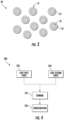
Fig. 2 illustrates a first powder material in accordance with one or more exemplary aspects of the present disclosure; -
Fig. 3 illustrates a second powder material in accordance with one or more exemplary aspects of the present disclosure; -
Fig. 4 illustrates a method for manufacturing a bulk dual phase soft magnetic component in accordance with one or more exemplary aspects of the present disclosure; -
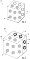
Fig. 5 illustrates a component structure comprising a powder combination in accordance with one or more exemplary aspects of the present disclosure; -
Fig. 6 illustrates a bulk dual phase soft magnetic component formed from a component structure in accordance with one or more exemplary aspects of the present disclosure; and -
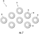
Fig. 7 illustrates another embodiment of the first powder material in accordance with one or more exemplary aspects of the present disclosure. - Repeat use of reference characters in the present specification and drawings is intended to represent the same or analogous features or elements of the present disclosure.
- Reference will now be made in detail to present embodiments of the disclosure, one or more examples of which are illustrated in the accompanying drawings. The detailed description uses numerical and letter designations to refer to features in the drawings. Like or similar designations in the drawings and description have been used to refer to like or similar parts of the disclosure.
- The word "exemplary" is used herein to mean "serving as an example, instance, or illustration." Any implementation described herein as "exemplary" is not necessarily to be construed as preferred or advantageous over other implementations. Additionally, unless specifically identified otherwise, all embodiments described herein should be considered exemplary.
- As used herein, the terms "first", "second", and "third" may be used interchangeably to distinguish one component from another and are not intended to signify location or importance of the individual components.
- The singular forms "a", "an", and "the" include plural references unless the context clearly dictates otherwise.
- Here and throughout the specification and claims, range limitations are combined and interchanged, such ranges are identified and include all the sub-ranges contained therein unless context or language indicates otherwise. For example, all ranges disclosed herein are inclusive of the endpoints, and the endpoints are independently combinable with each other.
- As used herein, "combination", "combinations" and the like are used to describe any collection of different materials, whether or not said materials are adjacent one another, interspersed, or partially mixed and whether or not the combination of different materials is symmetrical.
- As used herein, the terms "integral", "unitary", "monolithic", or "bulk" as used to describe a structure refers to the structure being formed integrally of a continuous material or group of materials with no seams, connections joints, or the like. The integral, unitary structures described herein may be formed through additive manufacturing to have the described structure, or alternatively through a casting process, etc.
- As used herein, the term "additive manufacturing" refers generally to manufacturing technology in which components are manufactured in a layer-by-layer manner. An exemplary additive manufacturing machine may be configured to utilize any desired additive manufacturing technology.
- The present disclosure is generally related to a bulk dual phase soft magnetic component having a three-dimensional magnetic flux and methods for making the same. A bulk dual phase soft magnetic component can be formed by combining a first powder material with a second powder material to form a component structure and performing powder consolidation on the component structure. Specifically, the first powder material may contain a plurality of first particles. Each of the first particles may include a first core and a reactive coating. The second powder material may contain a plurality of second particles. Each second particle may include a second core and a non-reactive coating.
- Prior to powder consolidation, each first core may be generally ferromagnetic and contain an iron alloy in an initial phase (e.g., ferrite phase, martensite phase, or a duplex structure of both ferrite and martensite phases). Moreover, each second core may be generally ferromagnetic and contain an iron alloy in a maintained ferrite phase or martensite phase. During powder consolidation, the plurality of first particles may be consolidated with the plurality of second particles and nitrogen from each reactive coating may diffuse into each respective first core. The nitrogen may react with the first core and austenitize the iron alloy from its initial ferrite or martensite phase into a final austenite phase, which may result in the first cores becoming generally paramagnetic. Further, the non-reactive coating may allow the second cores to maintain their ferromagnetic properties and maintain the ferrite phase of the iron alloy within the second cores. Upon consolidation, the component structure may form a bulk dual phase soft magnetic component containing one or more magnetic regions and one or more non-magnetic regions.
- In this regard, a plurality of first particles can be combined with a plurality second particles to form a bulk dual phase soft magnetic components and/or powder combinations (such as for being used to form bulk dual phase soft magnetic components).
- As disclosed herein, the combination of first particles and second particles can thereby reduce flux leakage by having first particles loaded in the component structure at desired magnetic regions and second particles loaded in the component structure at desired non-magnetic regions, thereby increasing magnetic saturation of bulk dual phase components. Such bulk dual phase soft magnetic components may provide, for example, higher saturation flux density and/or lower eddy current loss in electrical components. Moreover, the bulk dual phase soft magnetic components disclosed herein may have a three-dimensional magnetic flux flow direction from the isotropic structure of the parts. That is, the localized magnetic and non-magnetic regions can reduce flux losses due to the relatively low and high magnetic permeability of the different regions with respect to one another. For instance, the magnetic regions can constrain the path of magnetic flux while the non-magnetic regions can enable the path for magnetic flux. Resulting bulk dual phase soft magnetic components can be used in axial and/or transverse flux machines, such as for stators in motors and generators for automobile, aviation, robotic, and/or appliance applications with improved continuous and peak power outputs, power density, power factor, and/or efficiency.
- Referring now to the drawings, wherein identical numerals indicate the same elements throughout the figures,
FIGS. 1-3 andFIG. 7 schematically illustrate apowder combination 10 and constituents thereof. Thepowder combination 10 can generally include a plurality offirst particles 21, such as fromfirst powder material 20, and a plurality ofsecond particles 31, such as fromsecond powder material 30. - With specific reference to
FIG. 1 , it should be appreciated that the plurality offirst particles 21 and the plurality ofsecond particles 31 may be combined to produce thepowder combination 10 in a variety of configurations. As defined from above, and now with further specific reference to thepowder combination 10, "combination" refers to any combination of the plurality offirst particles 21 and the plurality ofsecond particles 31, whether or not the plurality offirst particles 21 and the plurality ofsecond particles 31 are adjacent one another in respective regions or directly mixed with one another, and whether or not the combination of the plurality offirst particles 21 and the plurality ofsecond particles 31 is symmetrical. - For example, the plurality of
first particles 21 and the plurality ofsecond particles 31 may be located within their own respective regions adjacent to one another, such as is illustrated inFIG. 1 . That is, individual particles of thefirst powder material 20 and individual particles of the second powder material may have little or negligible direct mixing with one another such that respective groups of the plurality offirst particles 21 and the plurality ofsecond particles 31 are merely adj acent to one another within thepowder combination 10, or anything therebetween. Alternatively, the plurality offirst particles 21 and the plurality ofsecond particles 31 may comprise a partial mixing, wherein both the plurality offirst particles 21 and the plurality ofsecond particles 31 are partially mixed within thepowder combination 10. - Thus, in some embodiments, the
powder combination 10 may essentially comprise a heterogeneous combination of the plurality offirst particles 21 and a plurality ofsecond particles 31, wherein different regions are comprised of the same respective types of particles. In such embodiments, thepowder combination 10 may comprise, at a minimum, two distinct regions wherein one comprises the plurality offirst particles 21 and the other comprises the plurality ofsecond particles 31. In further embodiments, multiple regions may be present of the respective plurality offirst particles 21 and plurality ofsecond particles 31 such as through layering, stacking, or other variations, either symmetrically or asymmetrically. - Referring now to
FIG. 2 , afirst powder material 20 containing a plurality offirst particles 21 is shown. Each first particle of the plurality offirst particles 21 generally comprises afirst core 22 and areactive coating 23. Eachfirst core 22 can generally comprise any material susceptible to austenitizing, such as materials having a high-saturation of iron. In some embodiments, eachfirst core 22 may comprise an iron alloy in an initial phase (e.g., ferrite or martensite). Examples of such iron alloys may include, as alloying elements in addition to iron, chromium, manganese, or a combination thereof. However, the composition of iron alloy in the initial phase is not limited and may include virtually any iron alloy susceptible to austenitization. - Each first particle of the plurality of
first particles 21 can further comprise areactive coating 23 around thefirst core 22. For purposes of the present disclosure, a reactive coating is a coating material that comprises a nitrogen compound having the ability to react with and austenitize thefirst core 22 during powder consolidation. For example, reactive nitrogen compounds may include various nitrides, such as silicon nitride, chromium nitride, iron nitride, aluminum nitride, titanium nitride, or a combination thereof. However, to limit eddy current loss, the reactive nitrogen compound is preferably selected to further impart the plurality offirst particles 21 with electrically insulative properties, such as to produce areactive coating 23 that has an electrical resistance at least 50%, 75%, or 100% greater than the electrical resistance of thefirst core 22. For instance, the reactive nitrogen compound may include silicon nitride. - Each first particle of the plurality of
first particles 21 may comprise a variety of overall shapes, sizes, and combinations. For example, in some embodiments, each first particle may generally comprise a particle size, wherein particle size refers to the largest dimension across an individual particle, of 0.001 mm to 0.5 mm, such as 0.01 mm to 0.4 mm, such as 0.1 mm to 0.3 mm, such as 0.1 mm to 0.25 mm. The plurality offirst particles 21 may comprise substantially similar particle sizes or may comprise a variety of different particle sizes such as through a multimodal distribution of various particle sizes. - The
reactive coating 23 can comprise a variety of different thicknesses. For example, in some embodiments, thereactive coating 23 may have an average thickness of 0.001 mm to 0.01 mm, such as 0.005 to 0.009 mm. In some embodiments, one or morereactive coatings 23 may comprise a substantially uniform thickness around the entire surface of one or more of the respective first particles. In some embodiments, one or morereactive coating 23 may comprise a non-uniform thickness around one or more of the respective first particles, such as wherein the thickness of thereactive coating 23 varies at different locations across the respective first particle. Such uniformities or variations in thickness may be an intended design selection or merely an acceptable byproduct of a particular manufacturing process. Additionally, eachreactive coating 23 may comprise substantially the same thicknesses or may comprise a variety of different thicknesses. However,first particles 21 with relatively large particle sizes generally includereactive coatings 23 with relatively larger thicknesses, as more nitrogen is required in thereactive coatings 23 to austenitize relatively largefirst cores 22. - In some embodiments, each first particle of the plurality of
first particles 21 may be substantially spherical. In such embodiments, the particle size may therefore equate to the diameter of the spherical particle. In some embodiments, each first particle may be non-spherical such as by having asymmetrical geometries. In some embodiments, each first particle may comprise a plurality of different shapes, such as a combination of spherical and asymmetrical particles. Moreover, the plurality offirst particles 21 may comprise substantially the same shape, or may comprise a variety of different shapes. - In some embodiments, the plurality of
first particles 21 can be provided as afirst powder material 20. Thefirst powder material 20 can comprise a plurality offirst particles 21 and optionally one or more additional additives. The plurality offirst particles 21 can be uniform, distinct, or a combination thereof. The optional one or more additional additives may comprise any material that may be utilized in powder metallurgy such as, for example, one or more powder consolidating agents (e.g., sintering agents). - The
first powder material 20 can comprise a plurality offirst particles 21 that are substantially uniform with one another, or may comprise a plurality offirst particles 21 that comprise one or more variations in one or more measurements and/or properties between individual first particles. For example, in some embodiments thefirst powder material 20 may comprise a plurality offirst particles 21 that all comprise substantially the same composition (i.e., similar compositions in thefirst cores 22 and the reactive coatings 23). In some embodiments, the pluralityfirst particles 21 may comprise some particles having afirst core 22 of a first size, shape, and composition, and some particles having afirst core 22 of a second size, shape, and composition, wherein at least one of the size, shape, and composition parameters are different between thefirst cores 22. Likewise, the plurality offirst particles 21 may comprise some particles having areactive coating 23 of a first size, shape, and composition, and some particles having areactive coating 23 of a second size, shape, and composition, wherein at least one of the size, shape, and composition parameters are different between thereactive coatings 23. It should thus be appreciated that afirst powder material 20 may comprise a plurality offirst particles 21 of the same or different compositions and/or properties within the scope of the embodiments disclosed herein. - Referring now to
FIGS. 1 and3 , thepowder combination 10 further comprises a plurality ofsecond particles 31, such as from asecond powder material 30. - Referring now to
FIG. 3 , each second particle of the plurality ofsecond particles 31 generally comprises asecond core 32 and anon-reactive coating 33. Eachsecond core 32 can generally comprise any material that is ferromagnetic, without regard to whether or not the material is susceptible to austenitization. In other words, the composition of iron alloy in a maintained ferrite or martensite phase is not limited, and may include virtually any ferromagnetic material, such as pure iron and ferromagnetic iron-containing alloys. - Each second particle of the plurality of
second particles 31 can further comprise anon-reactive coating 33 around thesecond core 32. Thenon-reactive coating 33 can comprise any material that electrically insulates thesecond core 32, such as by having an electrical resistance at least 50%, 75%, or 100% greater than the electrical resistance of thesecond core 32. For purposes of the present disclosure, thenon-reactive coatings 33 do not contain a reactive nitrogen compound and do not react with their respective core during powder consolidation, as compared to thereactive coatings 23. For example, in some embodiments, thenon-reactive coating 33 may comprise any non-reactive ceramic material. Thenon-reactive coating 33 around thesecond core 32 may, for example, similarly limit eddy current loss of a component formed by the methods such as those disclosed herein. - Each second particle of the plurality of
second particles 31 may comprise a variety of overall shapes, sizes, and combinations. For example, in some embodiments, each second particle may generally comprise particle size, wherein particle size refers to the largest dimension across an individual particle, of 0.001 mm to 0.5 mm, such as 0.01 such as 0.4 mm, such as 0.1 mm to 0.3 mm, such as 0.1 mm to 0.25 mm. The plurality ofsecond particles 31 may comprise substantially similar particle sizes or may comprise a variety of different particle sizes such as through a multimodal distribution of various particle sizes. - The
non-reactive coating 33 can comprise a variety of different thicknesses. For example, in some embodiments, thenon-reactive coating 33 may have a thickness of 0.001 mm to 0.01 mm, such as 0.005 to 0.009 mm. In some embodiments, one or morereactive coatings 23 may comprise a substantially uniform thickness around the entire surface of one or more of the respective second particles. In some embodiments, one or morenon-reactive coating 33 may comprise a non-uniform thickness around one or more of the respective second particles, such as wherein the thickness of thenon-reactive coating 33 varies at different locations across the respective second particle. Such uniformities or variations in thickness may be an intended design selection or merely an acceptable byproduct of a particular manufacturing process. Additionally, eachnon-reactive coating 33 may comprise substantially thicknesses or may comprise a variety of different thicknesses. - In some embodiments, each second particle of the plurality of
second particles 31 may be substantially spherical. In some embodiments, each second particle may be non-spherical such as by having asymmetrical geometries. In some embodiments, each second particle may comprise a plurality of different shapes, such as a combination of spherical and asymmetrical particles. Moreover, the plurality ofsecond particles 31 may comprise substantially the same shape, or may comprise a variety of different shapes. - In some embodiments, the plurality of
second particles 31 can be provided as asecond powder material 30. Thesecond powder material 30 can comprise a plurality ofsecond particles 31 and optionally one or more additional additives. The plurality ofsecond particles 31 can be uniform, distinct, or a combination thereof. The optional one or more additional additives may comprise any material that may be utilized in powder metallurgy such as, for example, one or more powder consolidating agents (e.g., sintering agents). - The
second powder material 30 can comprise a plurality ofsecond particles 31 that are substantially uniform with one another, or may comprise a plurality ofsecond particles 31 that comprise one or more variations in one or more measurements and/or properties between individual second particles. For example, in some embodiments thesecond powder material 30 may comprise a plurality ofsecond particles 31 that all comprise substantially the same composition (i.e., similar compositions in thesecond cores 32 and the non-reactive coatings 33). In some embodiments, the pluralitysecond particles 31 may comprise some particles having asecond core 32 of a first size, shape, and composition, and some particles having asecond core 32 of a second size, shape, and composition, wherein at least one of the size, shape, and composition parameters are different between thesecond cores 32. Likewise, the plurality ofsecond particles 31 may comprise some particles having anon-reactive coating 33 of a first size, shape, and composition, and some particles having anon-reactive coating 33 of a second size, shape, and composition, wherein at least one of the size, shape, and composition parameters are different between thenon-reactive coatings 33. It should thus be appreciated that asecond powder material 30 may comprise a plurality ofsecond particles 31 of the same or different compositions and/or properties within the scope of the embodiments disclosed herein. - In another embodiment, as shown in
FIG. 7 , thefirst powder material 20 may comprise a plurality offirst particles 21 that are each coated with a reactive coating 23 (as described herein) and anon-reactive coating 33 as described herein. For instance, areactive coating 23 may overly eachfirst core 22, and anon-reactive coating 33 may overly eachreactive coating 23. In such embodiments, thereactive coating 23 may include a reactive nitrogen compound that does not substantially limit the eddy current loss of eachfirst core 22, such as chromium nitride or iron nitride. Therefore, anon-reactive coating 33 as described herein may be employed, overlying eachreactive coating 23 with a non-reactive ceramic material to limit the eddy current loss of the plurality offirst particles 21. - With reference now to
FIGS. 1-3 and5 , thefirst powder material 20 and thesecond powder material 30 may be combined, such as to form a powder combination 10 (FIG. 1 ) and/or a component structure 50 (FIG. 5 ). As used herein, combine, combined, and variants thereof refers to any collective positioning of a plurality of particles, such as by combining them into a powder, combining them into a component shape, or otherwise combining the plurality of particles (e.g., in respective regions), either directly or indirectly. For instance, a plurality offirst particles 21 may be directly combined with a plurality ofsecond particles 31, afirst powder material 20 may be combined with asecond powder material 30, or a combination thereof. - As will be appreciated herein, the combined plurality of
first particles 21 and plurality ofsecond particles 31 may further be consolidated. For example, anunbonded component structure 50 may be formed comprising a plurality offirst particles 21 and plurality ofsecond particles 31. Thecomponent structure 50 may further be consolidated to join the pluralityfirst particles 21 and plurality ofsecond particles 31 so as to ultimately produce a bulk dual phase softmagnetic component 100. As will become appreciated herein, the powder consolidation may occur sequentially with the combining process, may occur simultaneously with the combining process, or combinations thereof. - Combining the plurality of
first particles 21 and plurality ofsecond particles 31 to form acomponent structure 50 may occur through a variety of suitable mechanisms. However, in one embodiment, the plurality offirst particles 21 and plurality ofsecond particles 31 are powder consolidated using a solid state powder consolidation process. Suitable solid state powder consolidation processes may include hot compaction, hot pressing, sintering, hot isostatic pressing, spark plasma sintering, brazing, powder extrusion, powder forging, powder rolling, thermal spraying, and thermal spraying. For example, in one aspect, a plurality offirst particles 21 and plurality ofsecond particles 31 are sintered via the application of heat below the melting points of the plurality offirst particles 21 and plurality ofsecond particles 31. For example, the solid state powder consolidating process may be performed at a temperature from 900°C to 1450°C, such as 1000°C to 1300°C, such as 1100°C to 1300°C, such as 1200°C to 1300°C. Upon powder consolidation, the bulk dual phase softmagnetic component 100 preferably has its temperature reduced at a relatively high cooling rate to prevent decomposition of the final austenite phase in thefirst cores 22 back into its initial ferrite or martensite phase, which may significantly increase the magnetic saturation flux density. - Within the temperature ranges generally employed in solid state powder consolidation, the solubility of nitrogen into the iron alloys 24 of the
first cores 22 is at its highest. Conversely, non-solid state consolidation methods such as, for example, selective laser sintering can operate at temperatures greatly exceeding 1450°C in order to liquify/make molten the metal alloy being powder consolidated. At such high temperatures, the solubility of nitrogen in the molten metal alloy is poor. However, some additive manufacturing process may be employed, such as binder jetting. - For example, in some instances, the plurality of
first particles 21 and plurality ofsecond particles 31 may be combined into molds, such as molds of acomponent structure 50. In such examples, the plurality offirst particles 21 and plurality ofsecond particles 31 may be combined together before, during and/or after being loaded into one or more molds which define thecomponent structure 50. The combined plurality offirst particles 21 and plurality ofsecond particles 31 in the mold can, for example, subsequently be pressed and/or heated to form a bulk dual phase softmagnetic component 100 as illustrated inFIG. 6 . - Prior to powder consolidation as described herein, each
first core 22 of the plurality offirst particles 21 may be ferromagnetic and contain an iron alloy in an initial ferrite or martensite phase. Moreover, prior to hear treatment, eachfirst particle 21 may include areactive coating 23. - In one embodiment, nitrogen may diffuse from one or more
reactive coating 23 into their respectivefirst cores 22, resulting in the one or morereactive coating 23 becoming nitrogen-depletedinsulative coatings 26. Moreover, the diffusion of nitrogen into the one or morefirst cores 22 may austenitize the iron alloy in an initial ferrite or martensite phase into a final austenite phase, which may result in the one or morefirst cores 22 becoming paramagnetic. Conversely, eachsecond core 32 may maintain its ferromagnetic properties before, during, and after powder consolidation, and may contain an iron alloy in a maintained ferrite or martensite phase. - As a result of combining the plurality of
first particles 21 and plurality ofsecond particles 31, and subsequent and/or simultaneous powder consolidation, a bulk dual phase softmagnetic component 100 can be produced. The bulk dual phase softmagnetic component 100 can thereby comprise a component that has a microstructure with one or morenon-magnetic regions 110 and one or moremagnetic regions 120. For example, the plurality ofnon-magnetic regions 110 may be formed via the pluralityfirst particles 21. Additionally, the plurality ofmagnetic regions 120 may be formed via the plurality ofsecond particles 31. Moreover, nitrogen-depletedinsulative coating 26 and thenon-reactive coating 33 may combine to form an insulation network within the bulk dual phase softmagnetic component 100. The insulation network can extend throughout the bulk dual phase softmagnetic component 100, including between the magnetic and non-magnetic regions. Thus, the insulation network can provide electrically insulative properties to the overall bulk dual phase softmagnetic components 100, even in light of the various magnetic and non-magnetic properties. The various regions and properties may be relatively distributed throughout the bulk dual phase softmagnetic component 100 as a result of the initial loading of the plurality offirst particles 21 and plurality ofsecond particles 31. As a result, bulk dual phase softmagnetic components 100 as disclosed herein may be monolithic and may have higher saturation flux density and/or lower eddy current loss. - Moreover, the bulk dual phase soft
magnetic components 100 disclosed herein may have a three dimensional magnetic flux flow direction from the isotropic structure of the parts. For example, based in part on the level of mixing of the plurality offirst particles 21 and plurality ofsecond particles 31, the three dimensional magnetic flux may vary in direction and value across different regions of the bulk dual phase softmagnetic component 100. The bulk dual phase softmagnetic component 100 may thereby be tailored to obtain the desired respective magnetic flux properties across its shape and surface by maintaining the respective plurality offirst particles 21 and plurality ofsecond particles 31 in respective regions with. For example, a first part of the bulk dual phase softmagnetic component 100 may comprise the plurality offirst particles 21 while a second part of the bulk dual phase softmagnetic component 100 may comprise the plurality ofsecond particles 31. As a result, the first part of the bulk dual phase softmagnetic component 100 will have a different magnetic flux flow direction and value with respect to the second part of the bulk dual phase softmagnetic component 100. Depending on the design for the bulk dual phase softmagnetic component 100, multiple permutations of the different regions may be strategically located about the bulk dual phase softmagnetic component 100. These regions may vary in concentration of the respective plurality offirst particles 21 and plurality ofsecond particles 31, either wholly or partially, to produce a highly tailorable bulk dual phase softmagnetic component 100 with highly tailorable variations of three dimensional magnetic flux flow direction(s) and value(s). In sum, the localized magnetic and non-magnetic regions can reduce flux losses due to the relatively low and high magnetic permeability of the different regions with respect to one another. For instance, the magnetic regions can constrain the path of magnetic flux while the non-magnetic regions can enable the path for magnetic flux. - The bulk dual phase soft
magnetic component 100 can comprise one or more of a variety of different potential components. For example, the bulk dual phase softmagnetic component 100 may comprise one or more components of axial and/or transverse flux machines, such as for stators in motors and generators for automobile, aviation, robotic, and/or appliance applications with improved continuous and peak power outputs, power density, power factor, and/or efficiency. - With additional reference now to
FIG. 4 , amethod 200 is illustrated for manufacturing a bulk dual phase softmagnetic component 100. - In some embodiments, the
method 200 may optionally comprise producing the plurality offirst particles 21 instep 202 and/or producing the plurality ofsecond particles 31 instep 204. Such production may be achieved throughout any suitable means and be dependent on the specific type of plurality offirst particles 21 and plurality ofsecond particles 31. For example, producing the plurality offirst particles 21 instep 202 may comprise coating eachfirst core 22 withreactive coatings 23. Likewise, producing the plurality ofsecond particles 31 instep 204 may comprise coating eachsecond core 32 with anon-reactive coating 33. - A wide variety of coating methods may be employed in producing the plurality of
first particles 21 and the plurality ofsecond particles 31. Such techniques include, but are not limited to, metallurgical methods including powder mixing and mechanical milling, and chemical methods, such as chemical vapor deposition processes, iron plasma deposition, and other conventional application processes known to those skilled in the art. - In some embodiments, the
method 200 may not comprise the explicit steps of producing the plurality offirst particles 21 instep 202 and/or producing the plurality ofsecond particles 31 instep 204. For example, the plurality offirst particles 21 and/or the plurality ofsecond particles 31 may already be provided through other suitable means. - The
method 200 can thereby either further comprise, or initially comprise, combining the plurality offirst particles 21 and the plurality ofsecond particles 31 to form acomponent structure 50 instep 210. - Combining the plurality of
first particles 21 and the plurality ofsecond particles 31 may be achieved through any suitable mechanism such as molds and/or other powder metallurgy manufacturing techniques as described herein. The plurality offirst particles 21 and the plurality ofsecond particles 31 may be combined in a single step or through a plurality of iterations. For example, the plurality offirst particles 21 and the plurality ofsecond particles 31 may be combined instep 210 as apowder combination 10 being placed into a mold to thereby fill the mold in a single step. For example, the plurality offirst particles 21 may be disposed in a first region that is vertically adjacent a plurality ofsecond particles 31 disposed in a second region (such as illustrated inFIG. 6 ). Such placement may occur through selective loading of a mold, additively manufacturing via different powder materials, or any other suitable technique. In some embodiments, the plurality offirst particles 21 and the plurality ofsecond particles 31 may be combined in a plurality of iterations, such as by disposing one or more layers (not illustrated) of the plurality offirst particles 21 and then one or more layers of the plurality ofsecond particles 31, and/or disposing varying respective concentrations of the plurality offirst particles 21 and the plurality ofsecond particles 31. - The
method 200 may further comprise powder consolidating thecomponent structure 50 instep 220. As discussed above, powder consolidation instep 220 can comprise any application of heat and/or pressure that facilitates the formation of a bulk dual phase softmagnetic component 100 such as by solid state sintering the plurality offirst particles 21 and the plurality ofsecond particles 31 to form thecomponent structure 50. Furthermore, powder consolidation instep 220 can occur for a variety of different times and through a variety of different techniques as described herein. - In some embodiments, powder consolidating the
component structure 50 instep 220 may occur subsequent to combining the plurality offirst particles 21 and the plurality ofsecond particles 31 instep 210. For example, if the plurality offirst particles 21 and the plurality ofsecond particles 31 are combined instep 210 by loading the plurality offirst particles 21 and the plurality ofsecond particles 31 into a mold to form thecomponent structure 50, thecomponent structure 50 may subsequently be heat treated instep 220 to produce a bulk dual phase softmagnetic component 100. - While
method 200 is illustrated as at least comprisingsteps 210 andsteps 220, it should be appreciated thatmethod 200 may further comprise one or more additional manufacturing steps within the scope of the present disclosure. For example,method 200 may further include one or more processing, treating, or finishing steps to the plurality offirst particles 21, the plurality ofsecond particles 31, thecomponent structure 50, and/or the bulk dual phase softmagnetic component 100. - This written description uses examples to disclose the present disclosure, including the best mode, and also to enable any person skilled in the art to practice the disclosure, including making and using any devices or systems and performing any incorporated methods. The patentable scope of the disclosure is defined by the claims, and may include other examples that occur to those skilled in the art. Such other examples are intended to be within the scope of the claims if they include structural elements that do not differ from the literal language of the claims, or if they include equivalent structural elements with insubstantial differences from the literal languages of the claims.
- Further aspects are provided by the subject matter of the following clauses:
A method for manufacturing a bulk dual phase soft magnetic component, the method comprising: combining a first powder material with a second powder material to form a component structure, wherein the first powder material comprises a plurality of first particles each comprising a first core and a reactive coating, and wherein the second powder material comprises a plurality of second particles each comprising a second core and a non-reactive coating; and, consolidating the component structure to join the plurality of first particles with the plurality of second particles. - The method of any clause herein, wherein consolidating the component structure is performed at a temperature of 900°C to 1450°C.
- The method of any clause herein, wherein, prior to consolidating the component structure, the first core of each of the plurality of first particles is ferromagnetic and comprises an iron alloy in an initial ferrite or martensite phase.
- The method of any clause herein, wherein the iron alloy comprises chromium, manganese, or a combination thereof.
- The method of any clause herein, wherein, subsequent to powder consolidating the component structure, each the first core of each of the plurality of first particles is paramagnetic and comprises an iron alloy in a final austenite phase.
- The method of any clause herein, wherein the first core of each of the plurality of first particles, the second core of each of the plurality of second particles, or both have a particle size of 0.001 mm to 0.5 mm.
- The method of any clause herein, wherein the first core or each of the plurality of first particles, the second core of each of the plurality of second particles, or both have a particle size of 0.001 mm to 0.25 mm.
- The method of any clause herein, wherein the reactive coating comprises a reactive nitrogen compound.
- The method of any clause herein, wherein the non-reactive coating comprises a non-reactive ceramic material.
- The method of any clause herein, wherein the reactive coating comprises silicon nitride.
- The method of any clause herein, wherein the reactive coating, the non-reactive coating, or both have a thickness of 0.001 mm to 0.01 mm.
- The method of any clause herein, wherein combining the first powder material with the second powder material comprises: loading the first powder material and the second powder material into a mold.
- The method of any clause herein, further comprising: prior to combining the first powder material with the second powder material, coating the first core or each of the plurality of first particles with the reactive coating.
- The method of any clause herein, further comprising: prior to combining the first powder material with the second powder material, coating the second core of each of the plurality of second particles with the non-reactive coating.
- The method of any clause herein, wherein the bulk dual phase soft magnetic component comprises one or more magnetic regions and one or more non-magnetic regions.
- The method of any clause herein, wherein the bulk dual phase soft magnetic component comprises an insulation network that extends throughout the one or more magnetic regions and the one or more non-magnetic regions.
- A bulk dual phase soft magnetic component comprising: a plurality of first particles powder consolidated with a plurality of second particles; wherein each of the plurality of first particles comprise a first core and a nitrogen-depleted insulative coating; wherein each of the plurality of second particles comprise a second core and a non-reactive coating; and wherein the bulk dual phase soft magnetic component comprises one or more magnetic regions and one or more non-magnetic regions, and wherein the bulk dual phase soft magnetic component comprises a three-dimensional magnetic flux flow direction.
- The bulk dual phase soft magnetic component of any clause herein, wherein the first core of each of the plurality of first particles is paramagnetic and comprises an iron alloy in a final austenite phase; and wherein, the second core of each of the plurality of second particles is ferromagnetic and comprises an iron alloy in a maintained ferrite or martensite phase.
- The bulk dual phase soft magnetic component of any clause herein, wherein the bulk dual phase soft magnetic component further comprises an insulation network that extends throughout the one or more magnetic regions and the one or more non-magnetic regions.
- The bulk dual phase soft magnetic component of any clause herein, wherein the non-reactive coating comprises a non-reactive ceramic material.
Claims (15)
- A method for manufacturing a bulk dual phase soft magnetic component (200, 100), the method comprising:combining a first powder material (20) with a second powder material (30) to form a component structure (210, 50), wherein the first powder material (20) comprises a plurality of first particles (21) each comprising a first core (22) and a reactive coating (23), and wherein the second powder material (30) comprises a plurality of second particles (31) each comprising a second core (32) and a non-reactive coating (33); and,consolidating the component structure (50, 220) to join the plurality of first particles (21) with the plurality of second particles (31).
- The method of claim 1, wherein powder consolidating the component structure (50, 220) is performed at a temperature of 900°C to 1450°C.
- The method according to any of the preceding claims, wherein, prior to powder consolidating the component structure (50, 220), each first core (22) is ferromagnetic and comprises an iron alloy in an initial ferrite phase.
- The method of claim 3, wherein the iron alloy comprises chromium, manganese, or a combination thereof.
- The method according to any of the preceding claims, wherein, subsequent to powder consolidating the component structure (50, 220), each first core (22) is paramagnetic and comprises an iron alloy in a final austenite phase.
- The method according to any of the preceding claims, wherein each first core (22), each second core (32), or both have a particle diameter of 0.001 mm to 0.5 mm.
- The method according to any of the preceding claims, wherein each first core (22), each second core (32), or both have a particle diameter of 0.001 mm to 0.25 mm.
- The method according to any of the preceding claims, wherein each reactive coating (23) comprises a reactive nitrogen compound.
- The method of claim 8, wherein the reactive nitrogen compound comprises silicon nitride.
- The method according to any of the preceding claims, wherein each non-reactive coating (33) comprises a non-reactive ceramic material.
- The method according to any of the preceding claims, wherein each reactive coating (23), each non-reactive coating (33), or both have a thickness of 0.001 mm to 0.01 mm.
- The method of according to any of the preceding claims, wherein combining the first powder material (20) with the second powder material (30, 210) comprises:
loading the first powder material (20) and the second powder material (30) into a mold. - The method according to any of the preceding claims, further comprising:
prior to combining the first powder material (20) with the second powder material (30), coating each first core (22) with the reactive coating (23) and coating each second core (32) with the non-reactive coating (33). - The method according to any of the preceding claims, wherein the bulk dual phase soft magnetic component (200, 100) comprises one or more magnetic regions and one or more non-magnetic regions.
- The method of claim 14, wherein the bulk dual phase soft magnetic component (200, 100) comprises an insulation network that extends throughout the one or more magnetic regions and the one or more non-magnetic regions.
Applications Claiming Priority (1)
| Application Number | Priority Date | Filing Date | Title |
|---|---|---|---|
| US17/670,824 US12347593B2 (en) | 2022-02-14 | 2022-02-14 | Bulk dual phase soft magnetic components having three-dimensional magnetic flux and manufacturing methods |
Publications (1)
| Publication Number | Publication Date |
|---|---|
| EP4227022A1 true EP4227022A1 (en) | 2023-08-16 |
Family
ID=84799720
Family Applications (1)
| Application Number | Title | Priority Date | Filing Date |
|---|---|---|---|
| EP23150157.8A Pending EP4227022A1 (en) | 2022-02-14 | 2023-01-03 | Bulk dual phase soft magnetic components having three-dimensional magnetic flux and manufacturing methods |
Country Status (3)
| Country | Link |
|---|---|
| US (2) | US12347593B2 (en) |
| EP (1) | EP4227022A1 (en) |
| CN (1) | CN116598113A (en) |
Families Citing this family (1)
| Publication number | Priority date | Publication date | Assignee | Title |
|---|---|---|---|---|
| JP2025125416A (en) * | 2024-02-15 | 2025-08-27 | 株式会社デンソー | Rotating electric machine core, armature and rotating electric machine |
Citations (3)
| Publication number | Priority date | Publication date | Assignee | Title |
|---|---|---|---|---|
| US20080258102A1 (en) * | 2007-04-17 | 2008-10-23 | Fuji Electric Device Technology Co., Ltd. | Powder magnetic core and the method of manufacturing the same |
| WO2018128656A1 (en) * | 2017-01-06 | 2018-07-12 | General Electric Company | Core-shell alloy powder for additive manufacturing, an additive manufacturing method and an additively manufactured precipitation dispersion strengthened alloy component |
| CN110014144A (en) * | 2019-02-20 | 2019-07-16 | 益阳市再超粉末冶金有限公司 | A kind of powder metallurgy antifriction material for automobile gearbox |
Family Cites Families (34)
| Publication number | Priority date | Publication date | Assignee | Title |
|---|---|---|---|---|
| JPH04214205A (en) * | 1990-12-12 | 1992-08-05 | Fuji Electric Co Ltd | Thin-film magnetic head and its production |
| JP4399751B2 (en) | 1998-07-27 | 2010-01-20 | 日立金属株式会社 | Composite magnetic member, method for manufacturing ferromagnetic portion of composite magnetic member, and method for forming nonmagnetic portion of composite magnetic member |
| US6675460B2 (en) | 2001-10-03 | 2004-01-13 | Delphi Technologies, Inc. | Method of making a powder metal rotor for a synchronous reluctance machine |
| US6889419B2 (en) | 2002-04-16 | 2005-05-10 | Delphi Technologies, Inc. | Method of making a composite electric machine component of a desired magnetic pattern |
| US20050019558A1 (en) * | 2003-07-24 | 2005-01-27 | Amitabh Verma | Coated ferromagnetic particles, method of manufacturing and composite magnetic articles derived therefrom |
| JP2005085967A (en) | 2003-09-08 | 2005-03-31 | Fuji Electric Holdings Co Ltd | Composite magnetic particles and composite magnetic materials |
| JP4761835B2 (en) | 2005-01-25 | 2011-08-31 | 株式会社ダイヤメット | Mg-containing iron oxide coated iron powder |
| JP4707054B2 (en) | 2005-08-03 | 2011-06-22 | 住友電気工業株式会社 | Soft magnetic material, method for producing soft magnetic material, dust core, and method for producing dust core |
| US8273407B2 (en) * | 2006-01-30 | 2012-09-25 | Bergendahl Albert S | Systems and methods for forming magnetic nanocomposite materials |
| JP2007254768A (en) * | 2006-03-20 | 2007-10-04 | Aisin Seiki Co Ltd | SOFT MAGNETIC POWDER MATERIAL, ITS MANUFACTURING METHOD, SOFT MAGNETIC MOLDED BODY, ITS MANUFACTURING METHOD |
| CN101790765B (en) | 2007-08-30 | 2012-07-18 | 住友电气工业株式会社 | Soft magnetic material, dust core, method for producing soft magnetic material, and method for producing dust core |
| JP2009130286A (en) | 2007-11-27 | 2009-06-11 | Mitsubishi Materials Corp | High strength and high resistivity composite soft magnetic material manufacturing method and electromagnetic circuit component |
| JP5065960B2 (en) | 2008-03-28 | 2012-11-07 | 株式会社東芝 | High-frequency magnetic material and method for producing the same. |
| JP5482097B2 (en) | 2009-10-26 | 2014-04-23 | Tdk株式会社 | Soft magnetic material, dust core and method for manufacturing the same |
| US8840800B2 (en) | 2011-08-31 | 2014-09-23 | Kabushiki Kaisha Toshiba | Magnetic material, method for producing magnetic material, and inductor element |
| JP2013135071A (en) | 2011-12-26 | 2013-07-08 | Nissan Motor Co Ltd | Rare earth magnet compact and low temperature solidifying molding method |
| US9634549B2 (en) | 2013-10-31 | 2017-04-25 | General Electric Company | Dual phase magnetic material component and method of forming |
| US10673288B2 (en) | 2013-10-31 | 2020-06-02 | General Electric Company | Method for forming a nitrogenation barrier and machine formed using a body having the nitrogenation barrier |
| US10229776B2 (en) | 2013-10-31 | 2019-03-12 | General Electric Company | Multi-phase magnetic component and method of forming |
| US10229777B2 (en) | 2013-10-31 | 2019-03-12 | General Electric Company | Graded magnetic component and method of forming |
| US20150147217A1 (en) * | 2013-11-27 | 2015-05-28 | General Electric Company | Nanocomposite permanent magnets and method of making |
| KR102229915B1 (en) | 2014-02-10 | 2021-03-18 | 가부시키가이샤 닛신 세이훈 구루프혼샤 | Method for manufacturing magnetic particles |
| GB2545243B (en) | 2015-12-10 | 2017-12-13 | Rolls Royce Plc | Method of manufacturing a magnetically graded material |
| US9803139B1 (en) | 2016-06-24 | 2017-10-31 | General Electric Company | Process for removing aluminum-silicon coatings from metallic structures, and related processes for preparing magnetic components |
| US10748687B2 (en) * | 2018-03-12 | 2020-08-18 | General Electric Company | Methods of making a component with variable magnetization and related components |
| JP2019192868A (en) * | 2018-04-27 | 2019-10-31 | セイコーエプソン株式会社 | Insulator coating soft magnetic powder, dust core, magnetic element, electronic apparatus, and moving body |
| US10931157B2 (en) | 2018-05-07 | 2021-02-23 | General Electric Company | Unitary structure having magnetic and non-magnetic phases |
| US10937576B2 (en) | 2018-07-25 | 2021-03-02 | Kabushiki Kaisha Toshiba | Flaky magnetic metal particles, pressed powder material, rotating electric machine, motor, and generator |
| US11705258B2 (en) * | 2018-10-10 | 2023-07-18 | Powdermet, Inc. | High frequency low loss magnetic core and method of manufacture |
| US20200207022A1 (en) | 2018-12-31 | 2020-07-02 | Palo Alto Research Center Incorporated | Additive manufacturing device that applies a field to provide directional control of functional material |
| US10916269B2 (en) | 2019-02-19 | 2021-02-09 | Western Digital Technologies, Inc. | Magnet for motor of magnetic storage device |
| CN110164677B (en) | 2019-06-11 | 2020-11-06 | 莱芜职业技术学院 | Preparation of iron-based soft magnetic composite material wire for 3D printing |
| WO2021035117A1 (en) | 2019-08-21 | 2021-02-25 | Ut-Battelle, Llc | Indirect additive manufacturing process for fabricating bonded soft magnets |
| US12278031B2 (en) | 2019-11-11 | 2025-04-15 | Carpenter Technology Corporation | Soft magnetic composite materials and methods and powders for producing the same |
-
2022
- 2022-02-14 US US17/670,824 patent/US12347593B2/en active Active
-
2023
- 2023-01-03 EP EP23150157.8A patent/EP4227022A1/en active Pending
- 2023-02-13 CN CN202310106334.6A patent/CN116598113A/en active Pending
-
2025
- 2025-06-18 US US19/241,455 patent/US20250316410A1/en active Pending
Patent Citations (3)
| Publication number | Priority date | Publication date | Assignee | Title |
|---|---|---|---|---|
| US20080258102A1 (en) * | 2007-04-17 | 2008-10-23 | Fuji Electric Device Technology Co., Ltd. | Powder magnetic core and the method of manufacturing the same |
| WO2018128656A1 (en) * | 2017-01-06 | 2018-07-12 | General Electric Company | Core-shell alloy powder for additive manufacturing, an additive manufacturing method and an additively manufactured precipitation dispersion strengthened alloy component |
| CN110014144A (en) * | 2019-02-20 | 2019-07-16 | 益阳市再超粉末冶金有限公司 | A kind of powder metallurgy antifriction material for automobile gearbox |
Also Published As
| Publication number | Publication date |
|---|---|
| US20230260686A1 (en) | 2023-08-17 |
| CN116598113A (en) | 2023-08-15 |
| US12347593B2 (en) | 2025-07-01 |
| US20250316410A1 (en) | 2025-10-09 |
Similar Documents
| Publication | Publication Date | Title |
|---|---|---|
| JP7749750B2 (en) | motor | |
| Wu et al. | Toward additively manufactured electrical machines: Opportunities and challenges | |
| CN110459376B (en) | Monolithic structure with magnetic and non-magnetic phases | |
| US10229776B2 (en) | Multi-phase magnetic component and method of forming | |
| US20250316410A1 (en) | Reduced Common Mode Voltage Pulse Width Modulation Switching Scheme with Capacitor Voltage Balancing for a Multilevel Power Converter | |
| US20200149147A1 (en) | Structures Utilizing a Structured Magnetic Material and Methods for Making | |
| US12597811B2 (en) | Method of heat-treating additively manufactured ferromagnetic components | |
| EP3231889B1 (en) | Method of forming multi-phase magnetic component | |
| CN107230543B (en) | Graded magnetic assembly and method of forming | |
| EP3771560A1 (en) | Method of heat-treating additively-manufactured ferromagnetic components | |
| Lemieux et al. | Optimizing soft magnetic composites for power frequency applications and power-trains | |
| US12087483B2 (en) | Dual phase soft magnetic particle combinations, components and manufacturing methods |
Legal Events
| Date | Code | Title | Description |
|---|---|---|---|
| PUAI | Public reference made under article 153(3) epc to a published international application that has entered the european phase |
Free format text: ORIGINAL CODE: 0009012 |
|
| STAA | Information on the status of an ep patent application or granted ep patent |
Free format text: STATUS: THE APPLICATION HAS BEEN PUBLISHED |
|
| AK | Designated contracting states |
Kind code of ref document: A1 Designated state(s): AL AT BE BG CH CY CZ DE DK EE ES FI FR GB GR HR HU IE IS IT LI LT LU LV MC ME MK MT NL NO PL PT RO RS SE SI SK SM TR |
|
| STAA | Information on the status of an ep patent application or granted ep patent |
Free format text: STATUS: REQUEST FOR EXAMINATION WAS MADE |
|
| 17P | Request for examination filed |
Effective date: 20240209 |
|
| RBV | Designated contracting states (corrected) |
Designated state(s): AL AT BE BG CH CY CZ DE DK EE ES FI FR GB GR HR HU IE IS IT LI LT LU LV MC ME MK MT NL NO PL PT RO RS SE SI SK SM TR |
|
| STAA | Information on the status of an ep patent application or granted ep patent |
Free format text: STATUS: EXAMINATION IS IN PROGRESS |
|
| 17Q | First examination report despatched |
Effective date: 20251216 |