EP4227011A2 - Method for manufacturing electrode and classification system - Google Patents
Method for manufacturing electrode and classification system Download PDFInfo
- Publication number
- EP4227011A2 EP4227011A2 EP22210766.6A EP22210766A EP4227011A2 EP 4227011 A2 EP4227011 A2 EP 4227011A2 EP 22210766 A EP22210766 A EP 22210766A EP 4227011 A2 EP4227011 A2 EP 4227011A2
- Authority
- EP
- European Patent Office
- Prior art keywords
- mesh screen
- electrode material
- classifier
- electrode
- breakage
- Prior art date
- Legal status (The legal status is an assumption and is not a legal conclusion. Google has not performed a legal analysis and makes no representation as to the accuracy of the status listed.)
- Granted
Links
Images



Classifications
-
- B—PERFORMING OPERATIONS; TRANSPORTING
- B07—SEPARATING SOLIDS FROM SOLIDS; SORTING
- B07B—SEPARATING SOLIDS FROM SOLIDS BY SIEVING, SCREENING, SIFTING OR BY USING GAS CURRENTS; SEPARATING BY OTHER DRY METHODS APPLICABLE TO BULK MATERIAL, e.g. LOOSE ARTICLES FIT TO BE HANDLED LIKE BULK MATERIAL
- B07B1/00—Sieving, screening, sifting, or sorting solid materials using networks, gratings, grids, or the like
- B07B1/18—Drum screens
- B07B1/20—Stationary drums with moving interior agitators
-
- B—PERFORMING OPERATIONS; TRANSPORTING
- B02—CRUSHING, PULVERISING, OR DISINTEGRATING; PREPARATORY TREATMENT OF GRAIN FOR MILLING
- B02C—CRUSHING, PULVERISING, OR DISINTEGRATING IN GENERAL; MILLING GRAIN
- B02C19/00—Other disintegrating devices or methods
- B02C19/0056—Other disintegrating devices or methods specially adapted for specific materials not otherwise provided for
-
- B—PERFORMING OPERATIONS; TRANSPORTING
- B02—CRUSHING, PULVERISING, OR DISINTEGRATING; PREPARATORY TREATMENT OF GRAIN FOR MILLING
- B02C—CRUSHING, PULVERISING, OR DISINTEGRATING IN GENERAL; MILLING GRAIN
- B02C23/00—Auxiliary methods or auxiliary devices or accessories specially adapted for crushing or disintegrating not provided for in preceding groups or not specially adapted to apparatus covered by a single preceding group
- B02C23/08—Separating or sorting of material, associated with crushing or disintegrating
- B02C23/16—Separating or sorting of material, associated with crushing or disintegrating with separator defining termination of crushing or disintegrating zone, e.g. screen denying egress of oversize material
-
- B—PERFORMING OPERATIONS; TRANSPORTING
- B07—SEPARATING SOLIDS FROM SOLIDS; SORTING
- B07B—SEPARATING SOLIDS FROM SOLIDS BY SIEVING, SCREENING, SIFTING OR BY USING GAS CURRENTS; SEPARATING BY OTHER DRY METHODS APPLICABLE TO BULK MATERIAL, e.g. LOOSE ARTICLES FIT TO BE HANDLED LIKE BULK MATERIAL
- B07B1/00—Sieving, screening, sifting, or sorting solid materials using networks, gratings, grids, or the like
- B07B1/42—Drive mechanisms, regulating or controlling devices, or balancing devices, specially adapted for screens
-
- B—PERFORMING OPERATIONS; TRANSPORTING
- B07—SEPARATING SOLIDS FROM SOLIDS; SORTING
- B07B—SEPARATING SOLIDS FROM SOLIDS BY SIEVING, SCREENING, SIFTING OR BY USING GAS CURRENTS; SEPARATING BY OTHER DRY METHODS APPLICABLE TO BULK MATERIAL, e.g. LOOSE ARTICLES FIT TO BE HANDLED LIKE BULK MATERIAL
- B07B1/00—Sieving, screening, sifting, or sorting solid materials using networks, gratings, grids, or the like
- B07B1/46—Constructional details of screens in general; Cleaning or heating of screens
-
- B—PERFORMING OPERATIONS; TRANSPORTING
- B07—SEPARATING SOLIDS FROM SOLIDS; SORTING
- B07B—SEPARATING SOLIDS FROM SOLIDS BY SIEVING, SCREENING, SIFTING OR BY USING GAS CURRENTS; SEPARATING BY OTHER DRY METHODS APPLICABLE TO BULK MATERIAL, e.g. LOOSE ARTICLES FIT TO BE HANDLED LIKE BULK MATERIAL
- B07B13/00—Grading or sorting solid materials by dry methods, not otherwise provided for; Sorting articles otherwise than by indirectly controlled devices
- B07B13/14—Details or accessories
- B07B13/18—Control
-
- H—ELECTRICITY
- H01—ELECTRIC ELEMENTS
- H01M—PROCESSES OR MEANS, e.g. BATTERIES, FOR THE DIRECT CONVERSION OF CHEMICAL ENERGY INTO ELECTRICAL ENERGY
- H01M4/00—Electrodes
- H01M4/02—Electrodes composed of, or comprising, active material
- H01M4/04—Processes of manufacture in general
-
- H—ELECTRICITY
- H01—ELECTRIC ELEMENTS
- H01M—PROCESSES OR MEANS, e.g. BATTERIES, FOR THE DIRECT CONVERSION OF CHEMICAL ENERGY INTO ELECTRICAL ENERGY
- H01M4/00—Electrodes
- H01M4/02—Electrodes composed of, or comprising, active material
- H01M4/04—Processes of manufacture in general
- H01M4/0402—Methods of deposition of the material
- H01M4/0409—Methods of deposition of the material by a doctor blade method, slip-casting or roller coating
-
- B—PERFORMING OPERATIONS; TRANSPORTING
- B07—SEPARATING SOLIDS FROM SOLIDS; SORTING
- B07B—SEPARATING SOLIDS FROM SOLIDS BY SIEVING, SCREENING, SIFTING OR BY USING GAS CURRENTS; SEPARATING BY OTHER DRY METHODS APPLICABLE TO BULK MATERIAL, e.g. LOOSE ARTICLES FIT TO BE HANDLED LIKE BULK MATERIAL
- B07B13/00—Grading or sorting solid materials by dry methods, not otherwise provided for; Sorting articles otherwise than by indirectly controlled devices
- B07B13/14—Details or accessories
- B07B13/16—Feed or discharge arrangements
-
- H—ELECTRICITY
- H01—ELECTRIC ELEMENTS
- H01M—PROCESSES OR MEANS, e.g. BATTERIES, FOR THE DIRECT CONVERSION OF CHEMICAL ENERGY INTO ELECTRICAL ENERGY
- H01M4/00—Electrodes
- H01M4/02—Electrodes composed of, or comprising, active material
- H01M4/04—Processes of manufacture in general
- H01M4/0402—Methods of deposition of the material
- H01M4/0404—Methods of deposition of the material by coating on electrode collectors
-
- H—ELECTRICITY
- H01—ELECTRIC ELEMENTS
- H01M—PROCESSES OR MEANS, e.g. BATTERIES, FOR THE DIRECT CONVERSION OF CHEMICAL ENERGY INTO ELECTRICAL ENERGY
- H01M4/00—Electrodes
- H01M4/02—Electrodes composed of, or comprising, active material
- H01M4/13—Electrodes for accumulators with non-aqueous electrolyte, e.g. for lithium-accumulators; Processes of manufacture thereof
- H01M4/139—Processes of manufacture
-
- Y—GENERAL TAGGING OF NEW TECHNOLOGICAL DEVELOPMENTS; GENERAL TAGGING OF CROSS-SECTIONAL TECHNOLOGIES SPANNING OVER SEVERAL SECTIONS OF THE IPC; TECHNICAL SUBJECTS COVERED BY FORMER USPC CROSS-REFERENCE ART COLLECTIONS [XRACs] AND DIGESTS
- Y02—TECHNOLOGIES OR APPLICATIONS FOR MITIGATION OR ADAPTATION AGAINST CLIMATE CHANGE
- Y02E—REDUCTION OF GREENHOUSE GAS [GHG] EMISSIONS, RELATED TO ENERGY GENERATION, TRANSMISSION OR DISTRIBUTION
- Y02E60/00—Enabling technologies; Technologies with a potential or indirect contribution to GHG emissions mitigation
- Y02E60/10—Energy storage using batteries
Definitions
- JP 2014-102967 A discloses a filter for filtering a slurry for forming an active material layer.
- lithium cobalt oxide is represented by "LiCoO2”
- doping with a trace element, substitution with a trace element, etc. can be allowed.
- the mesh screen 120 has a tubular outer shape.
- the mesh screen 120 may have, for example, a cylindrical outer shape.
- the mesh screen 120 is located inside the body portion 111.
- the axis of the mesh screen 120 may coincide with the axis of the body portion 111.
- the blades 130 are connected to the rotor 140. Rotation of the shaft 151 causes the blades 130 to rotate along the inner peripheral surface of the mesh screen 120.
- an impact is applied to the mesh screen 120.
- this impact may break the mesh screen 120.
- the classifier 100 continues to operate after the mesh screen 120 is broken, the coarse particles 12 (specific foreign matter) may enter the first discharge portion 113 (non-defective side).
- the detector 200 may include, for example, a sound sensor (not shown) and an analyzer (not shown).
- the sound sensor measures the operation sound of the classifier 100.
- the analyzer collects and analyzes data on the operation sound.
- the analyzer may analyze, for example, the frequency of the operation sound.
- the analyzer may decompose the data on the operation sound into frequency components by, for example, Fast Fourier Transformation (FFT).
- FFT Fast Fourier Transformation
- the controller 300 can control the operation and cooperation of each device. For example, the controller 300 may stop operation of the classifier 100 when the detector 200 detects breakage of the mesh screen 120. For example, the controller 300 may determine that the electrode material contained in the classifier 100 is defective when the detector 200 detects breakage of the mesh screen 120. For example, the controller 300 may cause the electrode material contained in the classifier 100 to be discharged into the second discharge portion 114 (defective side) when the detector 200 detects breakage of the mesh screen 120.
- FIG. 4 is a schematic flowchart of a method for manufacturing an electrode according to the embodiment.
- the “method for manufacturing an electrode according to the embodiment” is sometimes simply referred to as the “manufacturing method.”
- the manufacturing method includes "(a) preparation of electrode material,” “(b) dry classification,” and “(c) manufacturing of electrode.”
- the manufacturing method includes preparing an electrode material.
- the electrode material contains active material powder.
- the electrode material may consist of, for example, active material powder.
- the electrode material may contain an additional component(s).
- the electrode material may contain, in addition to the active material powder, at least one selected from the group consisting of an electrically conductive material, a solid electrolyte, a binder, and an additive.
- the electrode material containing an additional component(s) such as a binder can also be referred to as "electrode mixture.”
- the electrode material may be prepared by mixing at least one selected from the group consisting of an electrically conductive material, a solid electrolyte, a binder, and an additive with the active material powder.
- the electrode material may be prepared by simple dry mixing.
- the active material powder and other material(s) may be compounded by mechanochemical treatment etc.
- the electrode material with a reduced content of specific foreign matter can be manufactured by the dry classification.
- the content of the magnetic matter in the electrode material is 4 ppm or less by mass fraction.
- the magnetic matter can include, for example, Fe, iron oxide, and SUS-derived components.
- the SUS-derived components may include, for example, Ni, chromium (Cr), and manganese (Mn).
- the content of the magnetic matter may be, for example, 2.2 ppm or less, 1.9 ppm or less, 1.8 ppm or less, or 1.3 ppm or less.
- the content of the magnetic matter may be zero.
- the magnetic matter can be quantified by the following procedure.
- Cu can be quantified by the following procedure. It should be noted that "1 ppm" can be the detection limit in this procedure.
- the manufacturing method includes manufacturing an electrode by using the electrode material subjected to the dry classification.
- the manufacturing method may include, for example, preparing a paint.
- the paint contains the electrode material.
- the electrode material in a dry state may be used as it is as the paint.
- wet powder may be prepared by mixing the electrode material and a solvent.
- the wet powder may contain, for example, granules (agglomerate of granulated particles).
- the solvent is liquid.
- the solvent can facilitate particle agglomeration of the wet powder.
- the solvent may contain, for example, water and an organic solvent.
- the solvent may contain a component that can dissolve the binder.
- the solvent may contain, for example, at least one selected from the group consisting of water, butyl butyrate, and NMP
- the manufacturing method may include, for example, coating a surface of a base material with the paint. Any desired coating method can be used in the manufacturing method.
- a first coating method and a second coating method, which will be described later, are merely by way of example.
- coating may be continuously performed by a roll-to-roll method. Such continuous coating is expected to improve productivity.
- the base material may be, for example, in the form of a sheet.
- the base material may be, for example, an electrode current collector.
- the base material may contain, for example, metal foil.
- the metal foil may contain, for example, at least one selected from the group consisting of aluminum (Al), Cu, Ni, titanium (Ti), Cr, and Fe.
- the base material may be, for example, Al foil or Cu foil.
- the base material may have a thickness of, for example, 5 ⁇ m to 50 ⁇ m, or 10 ⁇ m to 30 ⁇ m.
- FIG. 5 is a schematic view illustrating the first coating method.
- the first coating method is similar to liquid film transfer.
- a paint 20 may be, for example, wet powder.
- the paint 20 may have a solid content of, for example, 70% to 90%.
- a first roll 2101, a second roll 2102, and a third roll 2103 may be arranged side by side in the horizontal direction.
- the rotation axes of the rolls are parallel.
- the arrow shown in each roll indicates the rotational direction of that roll.
- first gap AB between the first roll 2101 and the second roll 2102.
- second gap BC between the second roll 2102 and the third roll 2103.
- the paint 20 is supplied into the first gap AB.
- An active material layer 32 is formed as the paint 20 is leveled in the first gap AB.
- the second roll 2102 transports the active material layer 32 into the second gap BC.
- the third roll 2103 transports a base material 31.
- the active material layer 32 is transferred to the base material 31 in the second gap BC. That is, an electrode 30 including the active material layer 32 and the base material 31 can be manufactured.
- FIG. 6 is a schematic view illustrating the second coating method. Electrostatic coating is performed in the second coating method.
- the paint 20 may be, for example, dry powder.
- the paint 20 may have a solid content of, for example, 90% to 100%.
- the rotation axes of a first roll 2201, a second roll 2202, and a third roll 2203 are parallel.
- the third roll 2203 may be located vertically above the first roll 2201.
- a power supply 2204 forms an electric field between the first roll 2201 and the third roll 2203.
- the first roll 2201 is provided with a magnet.
- the paint 20 is supplied to a container 2205.
- the paint 20 may be stirred in the container 2205.
- a ferromagnetic material may be mixed with the paint 20 in the container 2205.
- the paint 20 is attracted to the first roll 2201 by a magnetic force F1 from the first roll 2201.
- the first roll 2201 transports the paint 20.
- a substantially constant amount of the paint 20 is supplied into the gap between the first roll 2201 and the third roll 2203 as a squeegee 2206 scrapes off a part of the paint 20.
- the second roll 2202 transports the base material 31.
- the base material 31 is supplied into the gap between the first roll 2201 and the third roll 2203.
- An electric field is formed in the gap between the first roll 2201 and the third roll 2203 so that an electrostatic force F2 acting on the paint 20 is greater than the magnetic force F1 acting on the paint 20.
- the paint 20 is separated from the first roll 2201 by the electrostatic force F2.
- the paint 20 then flies toward the third roll 2203 due to the electrostatic force F2.
- the base material 31 is supported on the surface of the third roll 2203.
- the active material layer 32 can be formed as the paint 20 adheres to the surface of the base material 31. That is, the electrode 30 including the active material layer 32 and the base material 31 can be manufactured.
- the electrode (primary sheet) can be manufactured in the manner described above.
- the paint (active material layer) contains a solvent
- the electrode may be dried.
- the active material layer may be fixed to the base material by, for example, applying either or both of pressure and heat to the active material layer.
- the electrode may also be compressed to a predetermined thickness according to the battery design.
- the electrode may be cut into a predetermined planar shape according to the battery design.
- the active material layer may be formed only on one surface of the base material.
- the active material layer may be formed on both front and back surfaces of the base material.
- the active material layer may have a thickness of, for example, 10 ⁇ m to 1000 ⁇ m.
- the active material layer may have a thickness of, for example, 50 ⁇ m to 200 ⁇ m.
- the active material layer contains the electrode material. That is, the electrode includes the electrode material.
- the electrode material contains the active material powder.
- the content of the magnetic matter in the electrode material can also be 4 ppm or less.
- the content of Cu in the electrode material can also be 1 ppm or less.
- wet powder was produced by mixing the active material powder, the electrically conductive material, the binder, and the solvent in a planetary mixer. A three roll mill was prepared. The wet powder was kneaded by the three roll mill. The solid content of the wet powder was 75% or more.
- An electrode was manufactured by the first coating method (see FIG. 5 ).
- a test battery including electrodes was also manufactured.
- the test battery was a small laminated battery.
- a test battery was manufactured in a manner similar to that of Manufacturing Example 1 except that magnetic separation of the active material powder was performed before production of the wet powder. The content of specific foreign matter in the active material powder was measured after the magnetic separation. The results are shown in Table 2 below.
- a test battery was manufactured in a manner similar to that of Manufacturing Example 1 except that dry classification of the active material powder was performed before production of the wet powder. The content of specific foreign matter in the active material powder was measured after the dry classification. The results are shown in Table 2 below.
- test batteries (N1 to N4) were manufactured in each manufacturing example. A self-discharge test was performed on each test battery. The results are shown in Table 2 below. In Table 2, “OK” means that the voltage drop was 0.7 mV or less, and, and “NG” means that the voltage drop was more than 0.7 mV.
- a classification system was prepared.
- the classification system included a classifier and a detector.
- the detector was configured to detect breakage of a mesh screen by monitoring either or both of the operation sound of the classifier and the torque of a motor.
Landscapes
- Engineering & Computer Science (AREA)
- Manufacturing & Machinery (AREA)
- Chemical & Material Sciences (AREA)
- Chemical Kinetics & Catalysis (AREA)
- Electrochemistry (AREA)
- General Chemical & Material Sciences (AREA)
- Food Science & Technology (AREA)
- Battery Electrode And Active Subsutance (AREA)
- Combined Means For Separation Of Solids (AREA)
Abstract
Description
- This application claims priority to
Japanese Patent Application No. 2022-007047 filed on January 20, 2022 - The present disclosure relates to methods for manufacturing an electrode, classification systems, electrode materials, and electrodes.
-
Japanese Unexamined Patent Application Publication No. 2014-102967 JP 2014-102967 A - In the related art, an electrode is manufactured by application of a liquid paint. That is, a slurry is prepared by mixing an electrode material and a solvent. The electrode material can contain a binder, an electrically conductive material, etc. in addition to active material powder. An electrode is manufactured by coating a surface of a base material with the slurry.
- The solvent can dissolve the binder. The solvent also serves as a dispersion media for solid particles. The solvent can include, for example, an organic solvent. It is desired from the standpoint of, for example, manufacturing cost, environmental loads, etc. to reduce solvent usage associated with electrode manufacturing. Therefore, a process that does not use slurry has also been proposed. For example, a powder paint is prepared by mixing active material powder and a binder. The powder paint is wet powder or dry powder. An electrode can be manufactured by coating a surface of a base material with the powder paint.
- The active material powder is an agglomerate of active material particles. Active material particles cause electrode reactions. The active material powder ideally consists of active material particles. However, the active material powder can also contain a trace of foreign matter. Foreign matter is unintended impurities. Foreign matter contains metal. Foreign matter is considered to be generated by, for example, wear of equipment for producing active material powder. Foreign matter is in the form of particles. Foreign matter in the electrode may adversely affect battery performance. Such an influence of foreign matter tends to occur particularly when the foreign matter is coarse particles. For example, battery self-discharge may increase.
- Foreign matter can contain magnetic matter. Magnetic matter can include, for example, iron (Fe), iron oxides, and stainless steel (SUS)-derived components. In the related art, after the active material powder is synthesized, magnetic force separation (hereinafter referred to as "magnetic separation") of the active material powder is performed to reduce magnetic matter. However, the separation efficiency of the magnetic separation is not high enough. For example, active material particles such as lithium cobalt oxide can also be magnetic. When active material particles are magnetic, the foreign matter separation efficiency may decrease. This is because the active material particles are also attracted to a magnet. There is also foreign matter that is not magnetic. For example, copper (Cu) is not magnetic. Hereinafter, "foreign matter containing magnetic matter and Cu" is sometimes referred to as "specific foreign matter."
- In the related art, a slurry containing an electrode material is filtered with a filter to reduce specific foreign matter. However, this method cannot be applied to powder paints (wet powder, dry powder).
- The present disclosure provides a method for manufacturing an electrode, a classification system, an electrode material, and an electrode that reduce specific foreign matter (magnetic matter, Cu).
- Technical configurations and functions and effects of the present disclosure will be described below. An action mechanism according to the present specification includes estimation. The action mechanism does not limit the technical scope of the present disclosure.
- 1. In a method for manufacturing an electrode according to a first aspect of the present invention,
- an electrode material containing active material powder is prepared,
- dry classification of the electrode material is performed by a classifier, and an electrode is manufactured by using the electrode material subjected to the dry classification.
- According to the new knowledge of the present disclosure, specific foreign matter (magnetic matter, Cu) is coarse particles. The coarse particles can be separated from the electrode material by the dry classification. The dry classification can have high separation efficiency as compared to the method in which the slurry is filtered with a filter. That is, the specific foreign matter can be reduced as compared to the related art.
- A mesh screen is used in the dry classification. Mesh screens tend to break easily. A broken mesh screen may allow the specific foreign matter to enter an electrode. That is, there is room for improvement in quality stability.
- One possible method to detect breakage of a mesh screen is to monitor a change in electrical resistance of a mesh screen. That is, electrically conductive properties are given to the mesh screen. The electrical resistance of the mesh screen can increase when the mesh screen is broken. Breakage of the mesh screen can therefore be detected by an increase in electrical resistance. However, the electrode material can contain an electrically conductive material. When the electrode material contains an electrically conductive material, breakage of the mesh screen may not be able to be detected.
- Therefore, breakage of the mesh screen is detected by the operation sound of the classifier and the torque of the motor. Breakage of the mesh screen can thus be detected even when the electrode material contains an electrically conductive material. By detecting breakage of the mesh screen, an electrode with a reduced content of specific foreign matter can be stably manufactured. That is, the quality is expected to be stabilized.
- 2. The electrode material may contain an electrically conductive material.
- 3. Performing the dry classification of the electrode material by the classifier may include detecting a frequency component derived from the breakage of the mesh screen by analyzing a frequency of the operation sound.
- 4. Performing the dry classification of the electrode material by the classifier may include determining that the breakage has occurred when the torque falls out of a reference range.
- 5. Manufacturing the electrode by using the electrode material subjected to the dry classification may include
- preparing a paint containing the electrode material, and
- coating a surface of a base material with the paint.
- 6. The paint may have a solid content of 70% to 100% by mass fraction.
- The paint with a solid content of 70% to 100% can be a powder paint (wet powder, dry powder). A liquid paint (slurry) can have a solid content of, for example, 60% or less.
- 7. The classifier may be stopped when it is determined that the breakage has occurred.
The mesh screen may be replaced after stopping the classifier.
Operation of the classifier may be resumed after replacing the mesh screen. - 8. A second aspect of the present invention relates to a classification system that performs dry classification of an electrode material. The classification system includes a classifier and a detector.
The classifier includes a mesh screen, a blade, and a motor. The mesh screen has a tubular outer shape. The mesh screen is electrically insulating. The mesh screen is configured to separate coarse particles from the electrode material. The blade is configured to press the electrode material against the mesh screen. The motor is configured to rotate the blade along an inner peripheral surface of the mesh screen.
The detector is configured to detect breakage of the mesh screen by monitoring either or both of an operation sound of the classifier and torque of the motor. - 9. The detector may be configured to detect a frequency component derived from the breakage by analyzing a frequency of the operation sound.
- 10. The detector may be configured to determine that the breakage has occurred when the torque falls out of a reference range.
- 11. The classification system may further include a controller. The controller may be configured to stop the classifier when the breakage is detected by the detector.
- 12. The detector may be configured to determine that the electrode material contained in the classifier is defective when the breakage is detected.
The detector may be configured to redetermine that the electrode material determined to be defective is non-defective when the electrode material determined to be defective is subjected again to the dry classification. - 13. A third aspect of the present invention relates to an electrode material that includes active material powder. A content of magnetic matter in the active material powder is 4 ppm or less by mass fraction. A content of copper in the active material powder is 1 ppm or less by mass fraction.
- 14. A fourth aspect of the present invention relates to an electrode including the electrode material of the third aspect.
- Features, advantages, and technical and industrial significance of exemplary embodiments of the invention will be described below with reference to the accompanying drawings, in which like signs denote like elements, and wherein:
-
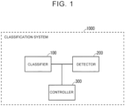
FIG. 1 is a block diagram of a classification system according to an embodiment; -
FIG. 2 is a first schematic sectional view showing an example of a classifier according to the embodiment; -
FIG. 3 is a second schematic sectional view showing an example of the classifier according to the embodiment; -
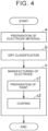
FIG. 4 is a schematic flowchart of a method for manufacturing an electrode according to the embodiment; -
FIG. 5 is a schematic view illustrating a first coating method; and -
FIG. 6 is a schematic view illustrating a second coating method. - Hereinafter, an embodiment of the present disclosure (hereinafter sometimes simply referred to as the "embodiment") and examples of the present disclosure (hereinafter sometimes simply referred to as the "examples") will be described. However, the embodiment and the examples are not intended to limit the technical scope of the present disclosure.
- In the present specification, the terms "comprise," "include," "have," and variations thereof (e.g., "composed of') are open-ended. When any of the open-ended terms is used, it means that additional elements may or may not be included in addition to essential elements. The term "consist of' is closed-ended. However, even when the closed-ended term is used, it does not mean that additional elements such as normally accompanying impurities and elements irrelevant to the technique of the present disclosure are excluded. The term "substantially consist of' is semi-closed-ended. When the semi-closed-ended term is used, it means that it is allowed to add elements that do not substantially affect the basic and novel characteristics of the technique of the present disclosure.
- In the present specification, the words such as "may" and "can" are used in a permissive sense, meaning that "it is possible," rather than in a mandatory sense, meaning "must."
- In the present specification, elements in a singular form can also be plural unless otherwise specified. For example, the term "particle" can mean not only "one particle" but also an "agglomerate of particles (powder, powdery material, or group of particles)."
- In the present specification, the order in which a plurality of steps, actions, operations, etc. included in various methods is performed is not limited to the described order unless otherwise specified. For example, a plurality of steps may proceed in parallel. For example, the order of a plurality of steps may be reversed.
- In the present specification, the numerical ranges such as "m% to n%" are inclusive ranges including their upper and lower limit values unless otherwise specified. That is, "m% to n%" indicates the numerical range of "m% or more and n% or less." Further, "m% or more and n% or less" includes "more than m% and less than n%." A numerical value selected as desired from the numerical range may be set to a new upper limit value or a new lower limit value. For example, a new numerical range may be set by combining a numerical value in the numerical range and a numerical value shown in a different part of the present specification, in a table, in the drawings, etc.
- In the present specification, all numerical values should be interpreted as having the term "about" in front of them. The term "about" can mean, for example, ±5%, ±3%, or ±1%. All numerical values can be approximate values that can vary depending on the manner in which the technique of the present disclosure is used. All numerical values can be expressed in significant figures. A measured value can be an average value of a plurality of measurements. The number of measurements may be three or more, five or more, or ten or more. It is generally expected that the larger the number of measurements, the higher the reliability of the average value. A measured value can be rounded off based on the number of significant figures. A measured value can include an error etc. due to, for example, the detection limit of a measuring device.
- In the present specification, when a compound is represented by a stoichiometric composition formula (e.g., "LiCoO2"), the stoichiometric composition formula is merely a representative example of the compound. The compound may have a non-stoichiometric composition. For example, when lithium cobalt oxide is represented by "LiCoO2," lithium cobalt oxide is not limited to the composition ratio of "Li:Co:O = 1:1:2" and can contain lithium (Li), cobalt (Co), and oxygen (O) at any composition ratio, unless otherwise specified. Moreover, doping with a trace element, substitution with a trace element, etc. can be allowed.
- Geometric terms as used in the present specification (e.g., "parallel," "perpendicular," "orthogonal," etc.) should not be interpreted in a strict sense. For example, the term "parallel" may refer to the state deviating slightly from "parallel" in a strict sense. Geometric terms as used in the present specification may include, for example, tolerances, variations, etc. in terms of design, work, manufacturing, etc. The dimensional relationships in the drawings may not match the actual dimensional relationships. The dimensional relationships (length, width, thickness, etc.) in the drawings may have been changed in order to facilitate understanding of the technique of the present disclosure. Moreover, a part of the configurations may have been omitted.
- The term "electrode" as used in the present specification is a general term for positive and negative electrodes. An electrode may be a positive electrode or a negative electrode. Electrodes can be applied to any desired battery system. In the embodiment, an example in which electrodes are applied to a lithium-ion battery will be described.
- As used in the present specification, "D50" indicates the particle size at which the cumulative frequency reaches 50% in a volume-based particle size distribution when counted from the smallest particle size. Moreover, "D99" indicates the particle size at which the cumulative frequency reaches 99% in a volume-based particle size distribution when counted from the smallest particle size. D50 and D99 can be measured by a laser diffraction method.
- In the present specification, particles have a minor axis and a major axis. The "major axis" refers to the distance between the farthest two points on the contour line of a particle image. The "minor axis" refers to the diameter orthogonally crossing the line segment of the major axis at the midpoint of the line segment. The minor axis is sometimes equal to the major axis.
- The term "solid content" as used in the present specification refers to the total mass fraction of solid components in a paint. A component dissolved in a solvent (e.g., a polymer binder) is regarded as a solid component.
- The term "slurry" as used in the present specification refers to a dispersed system of a solid (powder) in a liquid (solvent). The term "wet powder" refers to a dispersed system of a liquid (solvent) in a solid (powder).
- In the present specification, the "volume resistivity (Ω·cm)" of powder can be measured by, for example, any of the "MCP-PD" series of powder resistivity analyzer made by Nittoseiko Analytech Co., Ltd. (or an equivalent product). The amount of sample is 2.0 g. The measurement load is 20 kN.
-
FIG. 1 is a block diagram of a classification system according to the embodiment. Hereinafter, the "classification system according to the embodiment" is sometimes simply referred to as the "classification system." Aclassification system 1000 includes aclassifier 100 and adetector 200. Theclassification system 1000 may further include, for example, acontroller 300. Theclassifier 100, thedetector 200, and thecontroller 300 may be separate and independent of each other, or may be integrated and indivisible. -
FIG. 2 is a first schematic sectional view showing an example of the classifier according to the embodiment. Theclassifier 100 performs dry classification of an electrode material (powder material 10). Theclassifier 100 includes ahousing 110, amesh screen 120,blades 130, arotor 140, and amotor 150. - The
housing 110 includes abody portion 111, asupply portion 112, afirst discharge portion 113, and asecond discharge portion 114. Thebody portion 111 has a tubular outer shape. Thebody portion 111 may have a cylindrical outer shape. Thebody portion 111 houses themesh screen 120, theblades 130, and therotor 140. Thesupply portion 112 extends so as to guide thepowder material 10 into thebody portion 111. Thefirst discharge portion 113 is located below thebody portion 111.Fine particles 11 are discharged from thefirst discharge portion 113. Thesecond discharge portion 114 is located on the side in the axial direction (Y-axis direction) of thebody portion 111.Coarse particles 12 are discharged from thesecond discharge portion 114. Thesecond discharge portion 114 extends so as to guide thecoarse particles 12 downward. - The
mesh screen 120 has a tubular outer shape. Themesh screen 120 may have, for example, a cylindrical outer shape. Themesh screen 120 is located inside thebody portion 111. The axis of themesh screen 120 may coincide with the axis of thebody portion 111. - The
mesh screen 120 is a mesh sieve. Themesh screen 120 separates thecoarse particles 12 from thepowder material 10. The size of thecoarse particles 12 to be separated can be determined by the mesh size of themesh screen 120. The mesh size of themesh screen 120 can be adjusted so that the coarse particles 12 (specific foreign matter) are not allowed to pass through themesh screen 120 and the fine particles 11 (electrode material) are allowed to pass through themesh screen 120. - The fine particles 11 (electrode material) can have a D99 of less than 50 µm. The
fine particles 11 may have a D99 of, for example, 30 µm to 40 µm. The coarse particles 12 (specific foreign matter) may have a minor axis of, for example, 50 µm or more. The minor axis of thecoarse particles 12 may be, for example, two to 10 times, two to five times, or two to three times the D99 of thefine particles 11. - The
mesh screen 120 is electrically insulating. Themesh screen 120 may be made of, for example, resin. Themesh screen 120 may be composed of, for example, at least one selected from the group consisting of polyester, polyamide, and polyarylate. - The
motor 150 rotates ashaft 151. Theshaft 151 is inserted through therotor 140. Rotation of theshaft 151 causes therotor 140 to rotate. The axes of theshaft 151, therotor 140, and themesh screen 120 may coincide with each other. - The
rotor 140 includes ascrew portion 141. Thescrew portion 141 is located below thesupply portion 112. Thescrew portion 141 spirally extends on the surface of therotor 140 along the rotation axis of therotor 140. As therotor 140 rotates, thescrew portion 141 transports thepowder material 10 into thebody portion 111. - The
blades 130 are connected to therotor 140. Rotation of theshaft 151 causes theblades 130 to rotate along the inner peripheral surface of themesh screen 120. -
FIG. 3 is a second schematic sectional view showing an example of the classifier according to the embodiment. The section ofFIG. 3 is orthogonal to the rotation axis ofshaft 151. Theblades 130 may extend in, for example, a radial pattern from theshaft 151 toward the inner peripheral surface of themesh screen 120. Theblades 130 may be, for example, in the shape of a plate. As theblades 130 move along the inner peripheral surface of themesh screen 120, thepowder material 10 is dispersed onto the inner peripheral surface of themesh screen 120. Thepowder material 10 is also pressed against themesh screen 120. Thefine particles 11 in thepowder material 10 pass through themesh screen 120 and are discharged from thefirst discharge portion 113. Thecoarse particles 12 in thepowder material 10 cannot pass through themesh screen 120. Thecoarse particles 12 move along the inner peripheral surface of themesh screen 120 in the Y-axis direction. Thecoarse particles 12 are discharged from thesecond discharge portion 114. - For example, as the
blades 130 press thepowder material 10 against themesh screen 120, an impact is applied to themesh screen 120. For example, this impact may break themesh screen 120. If theclassifier 100 continues to operate after themesh screen 120 is broken, the coarse particles 12 (specific foreign matter) may enter the first discharge portion 113 (non-defective side). - The
detector 200 detects breakage of themesh screen 120. Thebroken mesh screen 120 can change the operation sound of theclassifier 100. Thebroken mesh screen 120 can change the torque of themotor 150. Thedetector 200 detects breakage of themesh screen 120 by monitoring either or both of the operation sound of theclassifier 100 and the torque of themotor 150. Thedetector 200 may monitor either the operation sound or the torque, or may monitor both the operation sound and the torque. - The
detector 200 may include, for example, a sound sensor (not shown) and an analyzer (not shown). The sound sensor measures the operation sound of theclassifier 100. The analyzer collects and analyzes data on the operation sound. The analyzer may analyze, for example, the frequency of the operation sound. The analyzer may decompose the data on the operation sound into frequency components by, for example, Fast Fourier Transformation (FFT). Of the frequency components thus obtained, the frequency component derived from breakage of themesh screen 120 can be identified. Breakage of themesh screen 120 can be detected by detecting this frequency component. - The
detector 200 may include, for example, a torque sensor. The torque sensor measures the torque of themotor 150. The torque sometimes increases when themesh screen 120 is broken. The torque sometimes decreases when themesh screen 120 is broken. For example, a reference range (lower limit value, upper limit value) may be set for the torque. The torque can change within the reference range during steady operation. The torque may fall out of the reference range when themesh screen 120 is broken. It may be determined that themesh screen 120 is broken when the torque falls out of the reference range. - The
controller 300 can control the operation and cooperation of each device. For example, thecontroller 300 may stop operation of theclassifier 100 when thedetector 200 detects breakage of themesh screen 120. For example, thecontroller 300 may determine that the electrode material contained in theclassifier 100 is defective when thedetector 200 detects breakage of themesh screen 120. For example, thecontroller 300 may cause the electrode material contained in theclassifier 100 to be discharged into the second discharge portion 114 (defective side) when thedetector 200 detects breakage of themesh screen 120. - The defective material may be subjected again to the dry classification. The defective material subjected again to the dry classification may be determined to be a non-defective material.
-
FIG. 4 is a schematic flowchart of a method for manufacturing an electrode according to the embodiment. Hereinafter, the "method for manufacturing an electrode according to the embodiment" is sometimes simply referred to as the "manufacturing method." The manufacturing method includes "(a) preparation of electrode material," "(b) dry classification," and "(c) manufacturing of electrode." - The manufacturing method includes preparing an electrode material. The electrode material contains active material powder. The electrode material may consist of, for example, active material powder. The electrode material may contain an additional component(s). For example, the electrode material may contain, in addition to the active material powder, at least one selected from the group consisting of an electrically conductive material, a solid electrolyte, a binder, and an additive. The electrode material containing an additional component(s) such as a binder can also be referred to as "electrode mixture."
- For example, the electrode material may be prepared by mixing at least one selected from the group consisting of an electrically conductive material, a solid electrolyte, a binder, and an additive with the active material powder. For example, the electrode material may be prepared by simple dry mixing. For example, the active material powder and other material(s) may be compounded by mechanochemical treatment etc.
- The active material powder is a main component of the electrode material. In the electrode material, the active material powder may account for, for example, 50% to 100% by mass fraction. For example, the active material powder may have a D50 of, for example, 1 µm to 30 µm, or 5 µm to 20 µm.
- The active material powder may be, for example, powder of a positive electrode active material. The positive electrode active material may contain, for example, at least one selected from the group consisting of LiCoO2, LiNiO2, LiMnO2, LiMn2O4, Li(NiCoMn)O2, Li(NiCoAl)O2, and LiFePO4. For example, "(NiCoMn)" in "Li(NiCoMn)O2" indicates that the whole of the elements inside the parentheses is 1 in terms of the composition ratio. The individual components of "(NiCoMn)" can be contained at any composition ratio as long as the whole is 1. Li(NiCoMn)O2 may include, for example, Li(Ni1/3CO1/3Mn1/3)O2, Li(Ni0.5Co0.2Mn0.3)O2, and Li(Ni0.8Co0.1Mn0.1)O2.
- The active material powder may be, for example, powder of a negative electrode active material. The negative electrode active material may contain, for example, at least one selected from the group consisting of graphite, soft carbon, hard carbon, silicon, silicon oxide, tin, tin oxide, and Li4Ti5O12.
- The active material powder may be magnetic. For example, active materials containing a transition metal element such as Fe, cobalt (Co), or nickel (Ni) can be magnetic. For example, Li(NiCoMn)O2, Li(NiCoAl)O2, and LiFePO4 can be magnetic.
- The electrically conductive material may be in the form of powder. The electrically conductive material may include, for example, electrically conductive carbon particles and electrically conductive carbon fibers. The electrically conductive material may contain, for example, at least one selected from the group consisting of carbon black, vaporgrown carbon fibers (VGCFs), carbon nanotubes (CNTs), graphene flakes, and graphite. The carbon black may contain, for example, at least one selected from the group consisting of acetylene black, furnace black, channel black, and thermal black. For example, 0.1 parts by mass to 10 parts by mass of the electrically conductive material may be added per 100 parts by mass of the active material powder.
- The solid electrolyte may be in the form of powder. The solid electrolyte may contain, for example, at least one selected from the group consisting of a sulfide solid electrolyte, an oxide solid electrolyte, and a borohydride solid electrolyte. The solid electrolyte may contain, for example, at least one selected from the group consisting of Li2S-P2S5, LiI-Li2S-P2S5, LiBr-Li2S-P2S5, and LiI-LiBr-Li2S-P2S5. For example, 1 parts by volume to 100 parts by volume of the solid electrolyte may be added per 100 parts by volume of the active material powder.
- The binder may be in the form of powder. The binder may contain, for example, at least one selected from the group consisting of polyvinylidene difluoride (PVDF), polytetrafluoroethylene (PTFE), a polyvinylidene difluoride-hexafluoropropylene copolymer (PVDF-HFP), styrene butadiene rubber (SBR), carboxymethyl cellulose (CMC), polyimide (PI), polyamideimide (PAI), and polyacrylic acid (PAA). For example, 0.1 parts by mass to 10 parts by mass of the binder may be added per 100 parts by mass of the active material powder.
- The additive may be in the form of powder. The additive can have any desired function. The additive may contain, for example, lithium phosphate. For example, 0.01 parts by mass to 10 parts by mass of the additive may be added per 100 parts by mass of the active material powder.
- The electrically conductive material can interfere with detection of breakage of the mesh screen by the classifier from a change in electrical resistance. Since the manufacturing method uses the classification system described above, breakage of the mesh screen can also be detected when the electrode material contains the electrically conductive material. The electrically conductive material may have a volume resistivity of, for example, less than 1 × 10² Ω·cm. Table 1 below shows the relationship between the volume resistivity of various materials and whether detection of breakage from a change in electrical resistance is possible. There is a tendency that, when the volume resistivity is less than 1 × 10² Ω·cm, it is difficult to detect breakage from a change in electrical resistance.
Table 1 Material Volume Resistivity (Ω·cm) Detection of Mesh Screen Breakage from Change in Electrical Resistance Positive Electrode Active Material LiFePO4 < 1 × 10² Not Possible Positive Electrode Active Material Li(NiCoMn)O2 > 1 × 10² Possible Negative Electrode Active Material Natural Graphite < 1 Not Possible Electrically Conductive Material Acetylene Black < 1 Not Possible Additive Lithium Phosphate > 1 × 10⁶ Possible - The manufacturing method includes performing dry classification of the electrode material by the classifier. A material to be subjected to the dry classification may be only the active material powder, or may be the electrode mixture. The dry classification of the manufacturing method can be performed by the classification system described above. Coarse particles (specific foreign matter) can be separated from the electrode material by the dry classification. When breakage of the mesh screen is detected while the classifier is in operation, the electrode material contained in the classifier at that time will not be used for electrode manufacturing.
- The electrode material with a reduced content of specific foreign matter (magnetic matter, Cu) can be manufactured by the dry classification. The content of the magnetic matter in the electrode material is 4 ppm or less by mass fraction. The magnetic matter can include, for example, Fe, iron oxide, and SUS-derived components. The SUS-derived components may include, for example, Ni, chromium (Cr), and manganese (Mn). The content of the magnetic matter may be, for example, 2.2 ppm or less, 1.9 ppm or less, 1.8 ppm or less, or 1.3 ppm or less. The content of the magnetic matter may be zero.
- The content of Cu in the electrode material is 1 ppm or less by mass fraction. The content of Cu may be zero.
- The magnetic matter can be quantified by the following procedure.
- (1) N-methyl-2-pyrrolidone (NMP) is prepared as a dispersion medium. The electrode material is prepared as a sample. The sample is dispersed in the dispersion medium by a mixer. A particle dispersion is thus prepared.
- (2) A bar magnet is immersed in the particle dispersion to collect magnetic matter contained in the particle dispersion.
- (3) The bar magnet is removed from the particle dispersion. The magnetic matter attracted to the bar magnet is recovered. The magnetic matter may be recovered using, for example, an adhesive tape.
- (4) The maximum diameter (dmax) of the magnetic matter and the particle count of the magnetic matter are measured using a microscope.
- (5) The volume of the magnetic matter can be obtained by regarding the magnetic matter as spheres with a diameter of dmax. The density of the magnetic matter can be obtained from the composition of the magnetic matter. The mass fraction of the magnetic matter can be obtained from the volume, particle count, and density of the magnetic matter.
- Cu can be quantified by the following procedure. It should be noted that "1 ppm" can be the detection limit in this procedure.
- (1) The electrode material is prepared as a sample. A solution is formed by acid digestion of the sample.
- (2) The solution is filtered to recover the residue and the filtrate.
- (3) The residue is incinerated. After alkali fusion of the ash, acid extraction is performed.
- (4) A sample liquid is prepared by mixing the filtrate obtained in (2) and the extract obtained in (3). The volume of the sample solution is adjusted.
- (5) The sample solution is analyzed by inductively coupled plasma mass spectrometry (ICP-MS). The mass fraction of Cu is thus measured.
- The manufacturing method includes manufacturing an electrode by using the electrode material subjected to the dry classification.
- The manufacturing method may include, for example, preparing a paint. The paint contains the electrode material. For example, the electrode material in a dry state may be used as it is as the paint. For example, wet powder may be prepared by mixing the electrode material and a solvent. The wet powder may contain, for example, granules (agglomerate of granulated particles).
- The solvent is liquid. The solvent can facilitate particle agglomeration of the wet powder. The solvent may contain, for example, water and an organic solvent. The solvent may contain a component that can dissolve the binder. The solvent may contain, for example, at least one selected from the group consisting of water, butyl butyrate, and NMP
- The manufacturing method may include, for example, coating a surface of a base material with the paint. Any desired coating method can be used in the manufacturing method. A first coating method and a second coating method, which will be described later, are merely by way of example. For example, coating may be continuously performed by a roll-to-roll method. Such continuous coating is expected to improve productivity.
- The base material may be, for example, in the form of a sheet. The base material may be, for example, an electrode current collector. The base material may contain, for example, metal foil. The metal foil may contain, for example, at least one selected from the group consisting of aluminum (Al), Cu, Ni, titanium (Ti), Cr, and Fe. The base material may be, for example, Al foil or Cu foil. The base material may have a thickness of, for example, 5 µm to 50 µm, or 10 µm to 30 µm.
-
FIG. 5 is a schematic view illustrating the first coating method. The first coating method is similar to liquid film transfer. In the first coating method, apaint 20 may be, for example, wet powder. Thepaint 20 may have a solid content of, for example, 70% to 90%. - Three rolls are used in the first coating method. For example, a
first roll 2101, asecond roll 2102, and athird roll 2103 may be arranged side by side in the horizontal direction. The rotation axes of the rolls are parallel. The arrow shown in each roll indicates the rotational direction of that roll. - There is a first gap AB between the
first roll 2101 and thesecond roll 2102. There is a second gap BC between thesecond roll 2102 and thethird roll 2103. - The
paint 20 is supplied into the first gap AB. Anactive material layer 32 is formed as thepaint 20 is leveled in the first gap AB. Thesecond roll 2102 transports theactive material layer 32 into the second gap BC. Thethird roll 2103 transports abase material 31. Theactive material layer 32 is transferred to thebase material 31 in the second gap BC. That is, anelectrode 30 including theactive material layer 32 and thebase material 31 can be manufactured. -
FIG. 6 is a schematic view illustrating the second coating method. Electrostatic coating is performed in the second coating method. In the second coating method, thepaint 20 may be, for example, dry powder. Thepaint 20 may have a solid content of, for example, 90% to 100%. - The rotation axes of a
first roll 2201, asecond roll 2202, and athird roll 2203 are parallel. Thethird roll 2203 may be located vertically above thefirst roll 2201. Apower supply 2204 forms an electric field between thefirst roll 2201 and thethird roll 2203. Thefirst roll 2201 is provided with a magnet. - The
paint 20 is supplied to acontainer 2205. Thepaint 20 may be stirred in thecontainer 2205. For example, a ferromagnetic material may be mixed with thepaint 20 in thecontainer 2205. Thepaint 20 is attracted to thefirst roll 2201 by a magnetic force F1 from thefirst roll 2201. Thefirst roll 2201 transports thepaint 20. A substantially constant amount of thepaint 20 is supplied into the gap between thefirst roll 2201 and thethird roll 2203 as asqueegee 2206 scrapes off a part of thepaint 20. - The
second roll 2202 transports thebase material 31. Thebase material 31 is supplied into the gap between thefirst roll 2201 and thethird roll 2203. - An electric field is formed in the gap between the
first roll 2201 and thethird roll 2203 so that an electrostatic force F2 acting on thepaint 20 is greater than the magnetic force F1 acting on thepaint 20. Thepaint 20 is separated from thefirst roll 2201 by the electrostatic force F2. Thepaint 20 then flies toward thethird roll 2203 due to the electrostatic force F2. Thebase material 31 is supported on the surface of thethird roll 2203. Theactive material layer 32 can be formed as thepaint 20 adheres to the surface of thebase material 31. That is, theelectrode 30 including theactive material layer 32 and thebase material 31 can be manufactured. - The electrode (primary sheet) can be manufactured in the manner described above. When the paint (active material layer) contains a solvent, the electrode may be dried. The active material layer may be fixed to the base material by, for example, applying either or both of pressure and heat to the active material layer.
- The electrode may also be compressed to a predetermined thickness according to the battery design. The electrode may be cut into a predetermined planar shape according to the battery design.
- The active material layer may be formed only on one surface of the base material. The active material layer may be formed on both front and back surfaces of the base material. The active material layer may have a thickness of, for example, 10 µm to 1000 µm. The active material layer may have a thickness of, for example, 50 µm to 200 µm.
- The active material layer contains the electrode material. That is, the electrode includes the electrode material. The electrode material contains the active material powder. In the electrode, the content of the magnetic matter in the electrode material can also be 4 ppm or less. In the electrode, the content of Cu in the electrode material can also be 1 ppm or less.
- The following materials were prepared.
- Active material powder: LiFePO4
- Electrically conductive material: carbon nanotubes (CNTs)
- Binder: CMC, SBR
- Solvent: water
- The content of specific foreign matter (magnetic matter, Cu) in the active material powder was measured. The results are shown in Table 2 below.
- Wet powder was produced by mixing the active material powder, the electrically conductive material, the binder, and the solvent in a planetary mixer. A three roll mill was prepared. The wet powder was kneaded by the three roll mill. The solid content of the wet powder was 75% or more.
- An electrode was manufactured by the first coating method (see
FIG. 5 ). A test battery including electrodes was also manufactured. The test battery was a small laminated battery. - A test battery was manufactured in a manner similar to that of Manufacturing Example 1 except that magnetic separation of the active material powder was performed before production of the wet powder. The content of specific foreign matter in the active material powder was measured after the magnetic separation. The results are shown in Table 2 below.
- A test battery was manufactured in a manner similar to that of Manufacturing Example 1 except that dry classification of the active material powder was performed before production of the wet powder. The content of specific foreign matter in the active material powder was measured after the dry classification. The results are shown in Table 2 below.
- Four test batteries (N1 to N4) were manufactured in each manufacturing example. A self-discharge test was performed on each test battery. The results are shown in Table 2 below. In Table 2, "OK" means that the voltage drop was 0.7 mV or less, and, and "NG" means that the voltage drop was more than 0.7 mV.
Table 2 Manufacturing Example 1 Manufacturing Example 2 Manufacturing Example 3 Process of Reducing Foreign Matter No Process Performed Magnetic Separation Dry Classification Content of Specified Foreign Matter Magnetic Matter (ppm)1) 5.2 2.5 1.3 Cu (ppm) 1.4 1.2 ≤ 12) Self-Discharge Test N1 Voltage Drop (mV) 1.24 0.66 0.54 Judgement NG OK OK N2 Voltage Drop (mV) 0.98 0.98 0.66 Judgement NG NG OK N3 Voltage Drop (mV) 1.54 1.02 0.52 Judgement NG NG OK N4 Voltage Drop (mV) 1.10 0.59 0.36 Judgement NG OK OK 1) Mass fraction. The same applies to Table 3.
2) Detection limit or less. The same applies to Table 3. - There is a tendency that the higher the content of the specific foreign matter, the larger the voltage drop. The content of the specific foreign matter was the lowest in Manufacturing Example 3 (dry classification). The voltage drop in the self-discharge test was also the smallest in Manufacturing Example 3.
- A classification system was prepared. The classification system included a classifier and a detector. The detector was configured to detect breakage of a mesh screen by monitoring either or both of the operation sound of the classifier and the torque of a motor.
- In Manufacturing Example 4, the classifier was operated for six hours with the detector not in operation (OFF state). The content of the specific foreign matter was measured for each of the active material powder after one-hour classification, the active material powder after three-hour classification, and the active material powder after six-hour classification. The results are shown in Table 3 below.
- In Manufacturing Example 5, the classifier was operated for six hours with the detector in operation (ON state). When the detector detected breakage of the screen mesh, the classifier was stopped, the active material powder being classified was discharged, and the screen mesh was replaced. The operation of the classifier was resumed after the active material powder and the screen mesh are replaced. The content of the specific foreign matter was measured for each of the active material powder after one-hour classification, the active material powder after three-hour classification, and the active material powder after six-hour classification. The results are shown in Table 3 below.
Table 3 Manufacturing Example 4 Manufacturing Example 5 Detector (detects breakage of mesh screen) OFF ON After 1h Classification Content of Specified Foreign Matter Magnetic Matter (ppm) 1.4 2.2 Cu (ppm) ≤ 1 ≤ 1 After 3h Classification Content of Specified Foreign Matter Magnetic Matter (ppm) 1.9 1.8 Cu (ppm) ≤ 1 ≤ 1 After 6h Classification Content of Specified Foreign Matter Magnetic Matter (ppm) 4.3 1.9 Cu (ppm) 1.1 ≤ 1 - There is a tendency that the quality (content of specific foreign matter) is stabilized over a long period of time by detecting breakage of the screen mesh.
- The embodiment also supports a "method for manufacturing an electrode material."
The method for manufacturing an electrode material includes the following (a) and (b): - (a) preparing an electrode material containing active material powder; and
- (b) manufacturing an electrode material by performing dry classification of the electrode material by a classifier.
- The embodiment and the examples are illustrative in all respects. The embodiment and the examples are not restrictive. The technical scope of the present disclosure includes all modifications that fall within the meaning and scope equivalent to the claims. For example, it is planned from the beginning to extract desired configurations from the embodiment and the examples and combine the extracted configurations as desired.
Performing the dry classification of the electrode material by the classifier includes detecting breakage of the mesh screen by monitoring either or both of an operation sound of the classifier and torque of the motor. Performing the dry classification of the electrode material by the classifier includes stopping using the electrode material contained in the classifier for manufacturing of the electrode when the breakage of the mesh screen is detected.
The above (b) includes detecting breakage of the mesh screen by monitoring either or both of an operation sound of the classifier and torque of the motor.
Claims (14)
- A method for manufacturing an electrode, the method comprising:preparing an electrode material containing active material powder;performing dry classification of the electrode material by a classifier (100); andmanufacturing an electrode by using the electrode material subjected to the dry classification, wherein:the classifier (100) includes a mesh screen (120), a blade (130), and a motor (150);the mesh screen (120) has a tubular outer shape;the mesh screen (120) is electrically insulating;the mesh screen (120) is configured to separate coarse particles (12) from the electrode material;the blade (130) is configured to press the electrode material against the mesh screen (120);the motor (150) is configured to rotate the blade (130) along an inner peripheral surface of the mesh screen (120);performing the dry classification of the electrode material by the classifier (100) includes detecting breakage of the mesh screen (120) by monitoring either or both of an operation sound of the classifier (100) and torque of the motor (150); andperforming the dry classification of the electrode material by the classifier (100) includes stopping using the electrode material contained in the classifier (100) for manufacturing of the electrode (30) when the breakage of the mesh screen (120) is detected.
- The method according to claim 1, wherein the electrode material contains an electrically conductive material.
- The method according to claim 1 or 2, wherein performing the dry classification of the electrode material by the classifier (100) includes detecting a frequency component derived from the breakage by analyzing a frequency of the operation sound.
- The method according to any one of claims 1 to 3, wherein performing the dry classification of the electrode material by the classifier (100) includes determining that the breakage has occurred when the torque falls out of a reference range.
- The method according to any one of claims 1 to 4, wherein:manufacturing the electrode by using the electrode material subjected to the dry classification includespreparing a paint (20) containing the electrode material, andcoating a surface of a base material (31) with the paint (20); andthe paint (20) contains, in addition to the electrode material, at least one selected from the group consisting of an electrically conductive material, a solid electrolyte, a binder, and an additive.
- The method according to claim 5, wherein the paint (20) has a solid content of 70% to 100% by mass fraction.
- The method according to any one of claims 1 to 6, further comprising:stopping the classifier (100) when it is determined that the breakage has occurred;replacing the mesh screen (120) after stopping the classifier (100); andresuming operation of the classifier (100) after replacing the mesh screen (120).
- A classification system for performing dry classification of an electrode material, the classification system comprising:a classifier (100); anda detector (200), wherein:the classifier (100) includes a mesh screen (120), a blade (130), and a motor (150);the mesh screen (120) has a tubular outer shape;the mesh screen is electrically insulating;the mesh screen is configured to separate coarse particles (12) from the electrode material;the blade (130) is configured to press the electrode material against the mesh screen (120);the motor (150) is configured to rotate the blade (130) along an inner peripheral surface of the mesh screen (120); andthe detector (200) is configured to detect breakage of the mesh screen (120) by monitoring either or both of an operation sound of the classifier (100) and torque of the motor (150).
- The classification system according to claim 8, wherein the detector (200) is configured to detect a frequency component derived from the breakage by analyzing a frequency of the operation sound.
- The classification system according to claim 8 or 9, wherein the detector (200) is configured to determine that the breakage has occurred when the torque falls out of a reference range.
- The classification system according to any one of claims 8 to 10, further comprising a controller (300), wherein the controller (300) is configured to stop the classifier (100) when the breakage is detected by the detector (200).
- The classification system according to any one of claims 8 to 11, wherein:the detector (200) is configured to determine that the electrode material contained in the classifier (100) is defective when the breakage is detected; andthe detector (200) is configured to redetermine that the electrode material determined to be defective is non-defective when the electrode material determined to be defective is subjected again to the dry classification.
- An electrode material, comprising active material powder, wherein:a content of magnetic matter in the active material powder is 4 ppm or less by mass fraction; anda content of copper in the active material powder is 1 ppm or less by mass fraction.
- An electrode, comprising the electrode material according to claim 13.
Applications Claiming Priority (1)
| Application Number | Priority Date | Filing Date | Title |
|---|---|---|---|
| JP2022007047A JP7800147B2 (en) | 2022-01-20 | 2022-01-20 | Electrode manufacturing method |
Publications (3)
| Publication Number | Publication Date |
|---|---|
| EP4227011A2 true EP4227011A2 (en) | 2023-08-16 |
| EP4227011A3 EP4227011A3 (en) | 2023-10-18 |
| EP4227011B1 EP4227011B1 (en) | 2026-01-28 |
Family
ID=84370203
Family Applications (1)
| Application Number | Title | Priority Date | Filing Date |
|---|---|---|---|
| EP22210766.6A Active EP4227011B1 (en) | 2022-01-20 | 2022-12-01 | Method for manufacturing electrode and classification system |
Country Status (4)
| Country | Link |
|---|---|
| US (2) | US12103042B2 (en) |
| EP (1) | EP4227011B1 (en) |
| JP (1) | JP7800147B2 (en) |
| CN (1) | CN116460020A (en) |
Families Citing this family (1)
| Publication number | Priority date | Publication date | Assignee | Title |
|---|---|---|---|---|
| WO2025192226A1 (en) * | 2024-03-11 | 2025-09-18 | 出光興産株式会社 | Sulfide solid electrolyte production method and production apparatus |
Citations (1)
| Publication number | Priority date | Publication date | Assignee | Title |
|---|---|---|---|---|
| JP2014102967A (en) | 2012-11-20 | 2014-06-05 | Toyota Motor Corp | Filtration filter of slurry for active material layer formation |
Family Cites Families (33)
| Publication number | Priority date | Publication date | Assignee | Title |
|---|---|---|---|---|
| US2984357A (en) * | 1957-04-08 | 1961-05-16 | Kufferath Josef | Electrically heated screen for separating coarser material from accompanying fines |
| US3620368A (en) * | 1969-06-02 | 1971-11-16 | Dart Ind Inc | Classification of dry polymer beads |
| US3905897A (en) * | 1973-07-09 | 1975-09-16 | Simplicity Eng Co | Material classifying apparatus |
| US5096611A (en) * | 1989-05-25 | 1992-03-17 | Globe-Union Inc. | Process for the production of battery paste |
| DE4324066C2 (en) * | 1993-07-17 | 1995-11-30 | Reimelt Dietrich Kg | Screening device |
| IT1269841B (en) * | 1994-05-27 | 1997-04-15 | Himont Inc | PROCEDURE AND DEVICE FOR THE CLASSIFICATION OF SOLID PARTICLES |
| JP2001243947A (en) | 2000-02-29 | 2001-09-07 | Sony Corp | Method and apparatus for manufacturing lithium ion battery |
| US6679386B2 (en) * | 2001-05-31 | 2004-01-20 | Sizetec, Inc. | Low-density particle sizing apparatus and method |
| US6997325B2 (en) * | 2002-11-13 | 2006-02-14 | M-I L.L.C. | System and process for break detection in porous elements for screening or filtering |
| EP1806185B1 (en) * | 2004-10-18 | 2010-07-07 | Tsukasa Industry Co., Ltd. | Sieve and sifter comprising a sieve breakage detector |
| JP2006278031A (en) * | 2005-03-28 | 2006-10-12 | Mitsubishi Chemicals Corp | Method for producing positive electrode material for lithium secondary battery, positive electrode material for lithium secondary battery, positive electrode for lithium secondary battery and lithium secondary battery using the same |
| JP2008006383A (en) * | 2006-06-29 | 2008-01-17 | Turbo Kogyo Co Ltd | Detection device for screen tear of cylindrical screen type classifier |
| FR2906031B1 (en) * | 2006-09-14 | 2009-01-30 | Omya S A S Soc Par Actions Sim | DEVICE FOR CHARACTERIZING GRANULOMETRY OF POWDERS AND USES THEREOF. |
| JP2008100132A (en) * | 2006-10-17 | 2008-05-01 | Turbo Kogyo Co Ltd | Method and device for inspecting rupture of screen of screen type classifier |
| GB0714391D0 (en) * | 2007-07-24 | 2007-09-05 | Axiom Process Ltd | Vibratory screening apparatus |
| JP2010064049A (en) * | 2008-09-12 | 2010-03-25 | Mitsubishi Chemicals Corp | Vane for classifier, classifier, and method of manufacturing powder |
| JP5670104B2 (en) * | 2009-09-29 | 2015-02-18 | 日本碍子株式会社 | Positive electrode active material and lithium secondary battery |
| US9453091B2 (en) * | 2010-03-17 | 2016-09-27 | Nippon Shokubai Co., Ltd. | Method of producing water absorbent resin |
| KR20120005079A (en) * | 2010-07-08 | 2012-01-16 | 주식회사신화기공 | Vibration damper with damage control system of motor |
| JP2012069517A (en) * | 2010-08-25 | 2012-04-05 | Sumitomo Chemical Co Ltd | Manufacturing method of cathode material powder for fine lithium secondary battery |
| CN102723211B (en) * | 2012-05-08 | 2015-12-16 | 海博瑞恩电子科技无锡有限公司 | A kind of high-performance super capacitor and manufacturing process thereof |
| DE102013101517A1 (en) * | 2013-02-15 | 2014-08-21 | Thyssenkrupp Resource Technologies Gmbh | Classifier and method for operating a classifier |
| EP2778126A1 (en) | 2013-03-15 | 2014-09-17 | Clariant International Ltd. | Lithium transition metal phosphate secondary agglomerates and process for its manufacture |
| JP2015082379A (en) | 2013-10-22 | 2015-04-27 | 株式会社デンソー | Method for manufacturing electrode material, electrode material, electrode for nonaqueous electrolyte secondary batteries, and nonaqueous electrolyte secondary battery |
| US10118198B2 (en) * | 2016-03-09 | 2018-11-06 | Superior Industries, Inc. | Vibratory classifier apparatus |
| CN106000525A (en) * | 2016-07-11 | 2016-10-12 | 成都中牧生物药业有限公司 | Tooth jamming prevention screening and smashing machine |
| JP2018032604A (en) | 2016-08-26 | 2018-03-01 | トヨタ自動車株式会社 | Electrode manufacturing apparatus |
| CN106249772B (en) * | 2016-08-26 | 2018-04-17 | 泉州市汉威机械制造有限公司 | A kind of control method of servo motor |
| EP3659718B1 (en) * | 2018-11-29 | 2021-06-16 | ALLGAIER WERKE GmbH | Method and system for monitoring a filtering machine |
| JP6646130B1 (en) * | 2018-12-07 | 2020-02-14 | 住友化学株式会社 | Lithium secondary battery positive electrode active material precursor, method for producing lithium secondary battery positive electrode active material precursor, and method for producing lithium composite metal compound |
| JP2021150160A (en) * | 2020-03-19 | 2021-09-27 | トヨタ自動車株式会社 | Negative electrode active material, negative electrode, sulfide-based all-solid battery, and manufacturing method for negative electrode |
| JP7201635B2 (en) * | 2020-03-24 | 2023-01-10 | 東海カーボン株式会社 | Negative electrode material for lithium ion secondary battery and method for producing negative electrode material for lithium ion secondary battery |
| CN214865038U (en) * | 2020-11-16 | 2021-11-26 | 内蒙古正时生物科技有限公司 | Earthworm soil screening plant |
-
2022
- 2022-01-20 JP JP2022007047A patent/JP7800147B2/en active Active
- 2022-11-30 US US18/060,024 patent/US12103042B2/en active Active
- 2022-12-01 EP EP22210766.6A patent/EP4227011B1/en active Active
-
2023
- 2023-01-05 CN CN202310013327.1A patent/CN116460020A/en active Pending
-
2024
- 2024-08-21 US US18/810,691 patent/US12583016B2/en active Active
Patent Citations (1)
| Publication number | Priority date | Publication date | Assignee | Title |
|---|---|---|---|---|
| JP2014102967A (en) | 2012-11-20 | 2014-06-05 | Toyota Motor Corp | Filtration filter of slurry for active material layer formation |
Also Published As
| Publication number | Publication date |
|---|---|
| EP4227011A3 (en) | 2023-10-18 |
| US12583016B2 (en) | 2026-03-24 |
| JP2023105977A (en) | 2023-08-01 |
| EP4227011B1 (en) | 2026-01-28 |
| US20240408646A1 (en) | 2024-12-12 |
| JP7800147B2 (en) | 2026-01-16 |
| US12103042B2 (en) | 2024-10-01 |
| US20230226573A1 (en) | 2023-07-20 |
| CN116460020A (en) | 2023-07-21 |
Similar Documents
| Publication | Publication Date | Title |
|---|---|---|
| EP2760070B1 (en) | Slurry composition for use in forming lithium-ion secondary battery electrode, containing cellulose fiber as binder, and lithium-ion secondary battery electrode | |
| CN103891015B (en) | Composite active material for lithium secondary battery and manufacturing method thereof | |
| US6811923B1 (en) | Active material for anode of secondary cell and method for production thereof and non-aqueous electrolyte secondary cell, and recycled electronic functional material and method for recycling electronic functional material | |
| EP4024520A1 (en) | Cobalt-free positive electrode material and preparation method therefor, lithium ion battery positive electrode, and lithium ion battery | |
| WO2014140323A1 (en) | Lithium transition metal phosphate secondary agglomerates and process for its manufacture | |
| EP2778126A1 (en) | Lithium transition metal phosphate secondary agglomerates and process for its manufacture | |
| US12583016B2 (en) | Method for manufacturing electrode, classification system, and, electrode material | |
| EP4625546A1 (en) | Positive electrode active material, positive electrode, secondary battery, and electric device | |
| EP4160743A1 (en) | Positive electrode for non-aqueous electrolyte secondary battery, and non-aqueous electrolyte secondary battery, battery module and battery system using the same | |
| US20240234675A1 (en) | Method of producing electrode | |
| WO1998054773A1 (en) | Method of producing electrode for non-aqueous electrolytic cells | |
| JP2023082871A (en) | Electrode manufacturing method | |
| KR100526225B1 (en) | Positive electrode active material for secondary cell and nonaqueous electrolyte secondary cell using the same, and method for analysis of positive electrode active material for secondary cell | |
| EP4234638B1 (en) | Carbon black, slurry, and lithium ion secondary battery | |
| JP4703524B2 (en) | Method for producing positive electrode active material for secondary battery and method for producing non-aqueous electrolyte secondary battery | |
| JP2011076897A (en) | Negative electrode material for lithium ion secondary battery | |
| JP3927085B2 (en) | Method for analyzing positive electrode active material for secondary battery | |
| CN119118086B (en) | Manganese phosphate-based cathode materials, their preparation methods and applications | |
| EP4450575A1 (en) | Carbon black, slurry and lithium ion secondary battery | |
| CN121726327A (en) | A positive electrode sheet, its preparation method, and a secondary battery | |
| KR100502530B1 (en) | Method of producing an electrode for non-aqueous electrolytic cells | |
| EP4525092A1 (en) | Positive electrode composition, positive electrode, battery, method for manufacturing positive electrode formation coating liquid, method for manufacturing positive electrode, and method for manufacturing battery | |
| JPH1145705A (en) | Manufacture of electrode for nonaqueous electric battery | |
| JP2025104114A (en) | Carbon material dispersion composition, composite slurry, electrode film, secondary battery, and vehicle | |
| TW202135365A (en) | Graphene dispersion, positive electrode paste, and lithium ion battery positive electrode |
Legal Events
| Date | Code | Title | Description |
|---|---|---|---|
| PUAI | Public reference made under article 153(3) epc to a published international application that has entered the european phase |
Free format text: ORIGINAL CODE: 0009012 |
|
| STAA | Information on the status of an ep patent application or granted ep patent |
Free format text: STATUS: REQUEST FOR EXAMINATION WAS MADE |
|
| 17P | Request for examination filed |
Effective date: 20221215 |
|
| AK | Designated contracting states |
Kind code of ref document: A2 Designated state(s): AL AT BE BG CH CY CZ DE DK EE ES FI FR GB GR HR HU IE IS IT LI LT LU LV MC ME MK MT NL NO PL PT RO RS SE SI SK SM TR |
|
| PUAL | Search report despatched |
Free format text: ORIGINAL CODE: 0009013 |
|
| AK | Designated contracting states |
Kind code of ref document: A3 Designated state(s): AL AT BE BG CH CY CZ DE DK EE ES FI FR GB GR HR HU IE IS IT LI LT LU LV MC ME MK MT NL NO PL PT RO RS SE SI SK SM TR |
|
| RIC1 | Information provided on ipc code assigned before grant |
Ipc: H01M 4/139 20100101ALN20230913BHEP Ipc: H01M 4/04 20060101ALI20230913BHEP Ipc: B07B 13/18 20060101ALI20230913BHEP Ipc: B07B 1/20 20060101AFI20230913BHEP |
|
| RIC1 | Information provided on ipc code assigned before grant |
Ipc: B07B 1/20 20060101AFI20250731BHEP Ipc: B07B 13/18 20060101ALI20250731BHEP Ipc: H01M 4/04 20060101ALI20250731BHEP Ipc: H01M 4/139 20100101ALN20250731BHEP |
|
| GRAP | Despatch of communication of intention to grant a patent |
Free format text: ORIGINAL CODE: EPIDOSNIGR1 |
|
| STAA | Information on the status of an ep patent application or granted ep patent |
Free format text: STATUS: GRANT OF PATENT IS INTENDED |
|
| RIC1 | Information provided on ipc code assigned before grant |
Ipc: B07B 1/20 20060101AFI20250804BHEP Ipc: B07B 13/18 20060101ALI20250804BHEP Ipc: H01M 4/04 20060101ALI20250804BHEP Ipc: H01M 4/139 20100101ALN20250804BHEP |
|
| INTG | Intention to grant announced |
Effective date: 20250908 |
|
| GRAS | Grant fee paid |
Free format text: ORIGINAL CODE: EPIDOSNIGR3 |
|
| GRAA | (expected) grant |
Free format text: ORIGINAL CODE: 0009210 |
|
| STAA | Information on the status of an ep patent application or granted ep patent |
Free format text: STATUS: THE PATENT HAS BEEN GRANTED |
|
| AK | Designated contracting states |
Kind code of ref document: B1 Designated state(s): AL AT BE BG CH CY CZ DE DK EE ES FI FR GB GR HR HU IE IS IT LI LT LU LV MC ME MK MT NL NO PL PT RO RS SE SI SK SM TR |
|
| REG | Reference to a national code |
Ref country code: CH Ref legal event code: F10 Free format text: ST27 STATUS EVENT CODE: U-0-0-F10-F00 (AS PROVIDED BY THE NATIONAL OFFICE) Effective date: 20260128 Ref country code: GB Ref legal event code: FG4D |
|
| REG | Reference to a national code |
Ref country code: DE Ref legal event code: R096 Ref document number: 602022029218 Country of ref document: DE |
|
| REG | Reference to a national code |
Ref country code: IE Ref legal event code: FG4D |