EP4226880A1 - Surgical impact driver adaptors for applying directed torque and linear impact loads during surgical procedures - Google Patents
Surgical impact driver adaptors for applying directed torque and linear impact loads during surgical procedures Download PDFInfo
- Publication number
- EP4226880A1 EP4226880A1 EP23156014.5A EP23156014A EP4226880A1 EP 4226880 A1 EP4226880 A1 EP 4226880A1 EP 23156014 A EP23156014 A EP 23156014A EP 4226880 A1 EP4226880 A1 EP 4226880A1
- Authority
- EP
- European Patent Office
- Prior art keywords
- connector
- surgical
- impact driver
- driver adaptor
- adaptor
- Prior art date
- Legal status (The legal status is an assumption and is not a legal conclusion. Google has not performed a legal analysis and makes no representation as to the accuracy of the status listed.)
- Pending
Links
Images





Classifications
-
- A—HUMAN NECESSITIES
- A61—MEDICAL OR VETERINARY SCIENCE; HYGIENE
- A61B—DIAGNOSIS; SURGERY; IDENTIFICATION
- A61B17/00—Surgical instruments, devices or methods
- A61B17/16—Instruments for performing osteoclasis; Drills or chisels for bones; Trepans
- A61B17/1613—Component parts
- A61B17/1633—Sleeves, i.e. non-rotating parts surrounding the bit shaft, e.g. the sleeve forming a single unit with the bit shaft
-
- A—HUMAN NECESSITIES
- A61—MEDICAL OR VETERINARY SCIENCE; HYGIENE
- A61B—DIAGNOSIS; SURGERY; IDENTIFICATION
- A61B17/00—Surgical instruments, devices or methods
- A61B17/04—Surgical instruments, devices or methods for suturing wounds; Holders or packages for needles or suture materials
- A61B17/0401—Suture anchors, buttons or pledgets, i.e. means for attaching sutures to bone, cartilage or soft tissue; Instruments for applying or removing suture anchors
-
- A—HUMAN NECESSITIES
- A61—MEDICAL OR VETERINARY SCIENCE; HYGIENE
- A61B—DIAGNOSIS; SURGERY; IDENTIFICATION
- A61B17/00—Surgical instruments, devices or methods
- A61B17/16—Instruments for performing osteoclasis; Drills or chisels for bones; Trepans
- A61B17/1613—Component parts
- A61B17/1631—Special drive shafts, e.g. flexible shafts
-
- B—PERFORMING OPERATIONS; TRANSPORTING
- B25—HAND TOOLS; PORTABLE POWER-DRIVEN TOOLS; MANIPULATORS
- B25B—TOOLS OR BENCH DEVICES NOT OTHERWISE PROVIDED FOR, FOR FASTENING, CONNECTING, DISENGAGING, OR HOLDING
- B25B21/00—Portable power-driven screw or nut setting or loosening tools; Attachments for drilling apparatus serving the same purpose
- B25B21/007—Attachments for drilling apparatus for screw or nut setting or loosening
-
- B—PERFORMING OPERATIONS; TRANSPORTING
- B25—HAND TOOLS; PORTABLE POWER-DRIVEN TOOLS; MANIPULATORS
- B25B—TOOLS OR BENCH DEVICES NOT OTHERWISE PROVIDED FOR, FOR FASTENING, CONNECTING, DISENGAGING, OR HOLDING
- B25B21/00—Portable power-driven screw or nut setting or loosening tools; Attachments for drilling apparatus serving the same purpose
- B25B21/02—Portable power-driven screw or nut setting or loosening tools; Attachments for drilling apparatus serving the same purpose with means for imparting impact to screwdriver blade or nut socket
-
- B—PERFORMING OPERATIONS; TRANSPORTING
- B25—HAND TOOLS; PORTABLE POWER-DRIVEN TOOLS; MANIPULATORS
- B25B—TOOLS OR BENCH DEVICES NOT OTHERWISE PROVIDED FOR, FOR FASTENING, CONNECTING, DISENGAGING, OR HOLDING
- B25B21/00—Portable power-driven screw or nut setting or loosening tools; Attachments for drilling apparatus serving the same purpose
- B25B21/02—Portable power-driven screw or nut setting or loosening tools; Attachments for drilling apparatus serving the same purpose with means for imparting impact to screwdriver blade or nut socket
- B25B21/026—Impact clutches
-
- B—PERFORMING OPERATIONS; TRANSPORTING
- B25—HAND TOOLS; PORTABLE POWER-DRIVEN TOOLS; MANIPULATORS
- B25B—TOOLS OR BENCH DEVICES NOT OTHERWISE PROVIDED FOR, FOR FASTENING, CONNECTING, DISENGAGING, OR HOLDING
- B25B23/00—Details of, or accessories for, spanners, wrenches, screwdrivers
- B25B23/0007—Connections or joints between tool parts
- B25B23/0035—Connection means between socket or screwdriver bit and tool
-
- A—HUMAN NECESSITIES
- A61—MEDICAL OR VETERINARY SCIENCE; HYGIENE
- A61B—DIAGNOSIS; SURGERY; IDENTIFICATION
- A61B17/00—Surgical instruments, devices or methods
- A61B17/16—Instruments for performing osteoclasis; Drills or chisels for bones; Trepans
- A61B17/1613—Component parts
- A61B17/1622—Drill handpieces
- A61B17/1624—Drive mechanisms therefor
-
- A—HUMAN NECESSITIES
- A61—MEDICAL OR VETERINARY SCIENCE; HYGIENE
- A61B—DIAGNOSIS; SURGERY; IDENTIFICATION
- A61B17/00—Surgical instruments, devices or methods
- A61B17/16—Instruments for performing osteoclasis; Drills or chisels for bones; Trepans
- A61B17/1613—Component parts
- A61B17/1626—Control means; Display units
-
- A—HUMAN NECESSITIES
- A61—MEDICAL OR VETERINARY SCIENCE; HYGIENE
- A61B—DIAGNOSIS; SURGERY; IDENTIFICATION
- A61B17/00—Surgical instruments, devices or methods
- A61B17/16—Instruments for performing osteoclasis; Drills or chisels for bones; Trepans
- A61B17/1613—Component parts
- A61B17/1628—Motors; Power supplies
-
- A—HUMAN NECESSITIES
- A61—MEDICAL OR VETERINARY SCIENCE; HYGIENE
- A61B—DIAGNOSIS; SURGERY; IDENTIFICATION
- A61B17/00—Surgical instruments, devices or methods
- A61B17/56—Surgical instruments or methods for treatment of bones or joints; Devices specially adapted therefor
- A61B17/58—Surgical instruments or methods for treatment of bones or joints; Devices specially adapted therefor for osteosynthesis, e.g. bone plates, screws or setting implements
- A61B17/88—Osteosynthesis instruments; Methods or means for implanting or extracting internal or external fixation devices
- A61B17/8875—Screwdrivers, spanners or wrenches
-
- A—HUMAN NECESSITIES
- A61—MEDICAL OR VETERINARY SCIENCE; HYGIENE
- A61B—DIAGNOSIS; SURGERY; IDENTIFICATION
- A61B17/00—Surgical instruments, devices or methods
- A61B2017/00477—Coupling
- A61B2017/00486—Adaptors for coupling parts with incompatible geometries
-
- A—HUMAN NECESSITIES
- A61—MEDICAL OR VETERINARY SCIENCE; HYGIENE
- A61B—DIAGNOSIS; SURGERY; IDENTIFICATION
- A61B17/00—Surgical instruments, devices or methods
- A61B17/04—Surgical instruments, devices or methods for suturing wounds; Holders or packages for needles or suture materials
- A61B17/0401—Suture anchors, buttons or pledgets, i.e. means for attaching sutures to bone, cartilage or soft tissue; Instruments for applying or removing suture anchors
- A61B2017/0403—Dowels
-
- A—HUMAN NECESSITIES
- A61—MEDICAL OR VETERINARY SCIENCE; HYGIENE
- A61B—DIAGNOSIS; SURGERY; IDENTIFICATION
- A61B17/00—Surgical instruments, devices or methods
- A61B17/04—Surgical instruments, devices or methods for suturing wounds; Holders or packages for needles or suture materials
- A61B17/0401—Suture anchors, buttons or pledgets, i.e. means for attaching sutures to bone, cartilage or soft tissue; Instruments for applying or removing suture anchors
- A61B2017/0409—Instruments for applying suture anchors
-
- A—HUMAN NECESSITIES
- A61—MEDICAL OR VETERINARY SCIENCE; HYGIENE
- A61B—DIAGNOSIS; SURGERY; IDENTIFICATION
- A61B17/00—Surgical instruments, devices or methods
- A61B17/04—Surgical instruments, devices or methods for suturing wounds; Holders or packages for needles or suture materials
- A61B17/0401—Suture anchors, buttons or pledgets, i.e. means for attaching sutures to bone, cartilage or soft tissue; Instruments for applying or removing suture anchors
- A61B2017/044—Suture anchors, buttons or pledgets, i.e. means for attaching sutures to bone, cartilage or soft tissue; Instruments for applying or removing suture anchors with a threaded shaft, e.g. screws
-
- A—HUMAN NECESSITIES
- A61—MEDICAL OR VETERINARY SCIENCE; HYGIENE
- A61B—DIAGNOSIS; SURGERY; IDENTIFICATION
- A61B90/00—Instruments, implements or accessories specially adapted for surgery or diagnosis and not covered by any of the groups A61B1/00 - A61B50/00, e.g. for luxation treatment or for protecting wound edges
- A61B90/03—Automatic limiting or abutting means, e.g. for safety
- A61B2090/031—Automatic limiting or abutting means, e.g. for safety torque limiting
-
- B—PERFORMING OPERATIONS; TRANSPORTING
- B23—MACHINE TOOLS; METAL-WORKING NOT OTHERWISE PROVIDED FOR
- B23B—TURNING; BORING
- B23B23/00—Tailstocks; Centres
-
- B—PERFORMING OPERATIONS; TRANSPORTING
- B25—HAND TOOLS; PORTABLE POWER-DRIVEN TOOLS; MANIPULATORS
- B25B—TOOLS OR BENCH DEVICES NOT OTHERWISE PROVIDED FOR, FOR FASTENING, CONNECTING, DISENGAGING, OR HOLDING
- B25B13/00—Spanners; Wrenches
- B25B13/46—Spanners; Wrenches of the ratchet type, for providing a free return stroke of the handle
- B25B13/461—Spanners; Wrenches of the ratchet type, for providing a free return stroke of the handle with concentric driving and driven member
- B25B13/466—Spanners; Wrenches of the ratchet type, for providing a free return stroke of the handle with concentric driving and driven member the ratchet parts engaging in an axial direction
-
- B—PERFORMING OPERATIONS; TRANSPORTING
- B25—HAND TOOLS; PORTABLE POWER-DRIVEN TOOLS; MANIPULATORS
- B25B—TOOLS OR BENCH DEVICES NOT OTHERWISE PROVIDED FOR, FOR FASTENING, CONNECTING, DISENGAGING, OR HOLDING
- B25B23/00—Details of, or accessories for, spanners, wrenches, screwdrivers
- B25B23/14—Arrangement of torque limiters or torque indicators in wrenches or screwdrivers
- B25B23/141—Mechanical overload release couplings
Definitions
- This disclosure relates to the field of surgery, and more particularly to surgical impact driver adaptors for use when performing various surgical procedures.
- Some surgical procedures require implanting one or more suture anchors within bone. Multiple surgical tools are typically required to prepare a bone hole and insert a suture anchor into the bone hole for suture anchors that require impaction loads.
- An exemplary surgical impact driver adaptor may include, inter alia, a first connector adapted to receive a rotational force, a second connector, and an outer locking sleeve that includes a proximal end portion configured to interface with a boss of the first connector and a distal end portion configured to interface with the second connector.
- An anvil coupling includes a proximal end portion received within an inner bore of the boss of the first connector. The anvil coupling is substantially housed within the boss and the outer locking sleeve.
- the boss of the first connector provides a hammer feature, and the proximal end portion of the anvil coupling provides an anvil feature that is configured to mate with and engage the hammer feature.
- a disengagement spring is configured to bias the anvil feature and the hammer feature apart, thereby disengaging the second connector from receiving the rotational force until an axial force that exceeds a predefined threshold is applied to the first connector.
- An exemplary surgical method may include, inter alia, limiting a transfer of a rotational force from a powered surgical instrument to a surgical device until a sufficient axial force is applied to an impact driver adaptor from the powered surgical instrument during a surgical procedure.
- This disclosure is directed to surgical impact driver adaptors that may be connected between a powered surgical instrument and a driven surgical device when performing surgical procedures, such as those involving the implantation of a surgical implant into bone, for example.
- the surgical impact driver adaptors may limit a transfer of a rotational force from the powered surgical instrument to the surgical device until a sufficient axial force is applied to the impact driver adaptor from the powered surgical instrument.
- An exemplary surgical impact driver adaptor may include, inter alia, a first connector adapted to receive a rotational force, a second connector, and an outer locking sleeve that includes a proximal end portion configured to interface with a boss of the first connector and a distal end portion configured to interface with the second connector.
- An anvil coupling includes a proximal end portion received within an inner bore of the boss of the first connector. The anvil coupling is substantially housed within the boss and the outer locking sleeve.
- the boss of the first connector provides a hammer feature, and the proximal end portion of the anvil coupling provides an anvil feature that is configured to mate with and engage the hammer feature.
- a disengagement spring is configured to bias the anvil feature and the hammer feature apart, thereby disengaging the second connector from receiving the rotational force until an axial force that exceeds a predefined threshold is applied to the first connector
- Another exemplary impact driver adaptor may include, inter alia, a first connector adapted to receive a rotational force, a rotational component operably coupled to the first connector, and an engagement assembly configured to disengage the rotational component from receiving the rotational force until an axial force that exceeds a predefined threshold is applied to the first connector.
- a first connector of a surgical impact driver adaptor is configured to receive a rotational force from a powered surgical instrument.
- a rotational component of a surgical impact driver adaptor is configured to connect to a surgical device.
- a rotational component of a surgical impact drive adaptor is a drive shaft.
- a rotational component of a surgical impact driver adaptor is a second connector.
- an engagement assembly of a surgical impact driver adaptor includes a rear clutch cylinder, a front clutch cylinder, and a disengagement spring that is configured to bias the rear clutch cylinder and the front clutch cylinder apart until an axial force exceeds a predefined threshold.
- a rear clutch cylinder includes a first set of teeth that are configured to engage and mesh with a second set of teeth of a front clutch cylinder.
- a ramp is established at each location where a first set of teeth engage a second set of teeth.
- a rotational component of a surgical impact driver adaptor is a drive shaft that is fixedly secured to a front clutch cylinder and free to rotate relative to a rear clutch cylinder.
- a spring is arranged between a cap of a first connector and a rear clutch cylinder of a surgical impact driver adaptor.
- the spring is configured to dampen linear impact loads created by an axial force.
- an engagement assembly of a surgical impact driver adaptor includes a hammer feature provided by a first connector, an anvil feature provided by an anvil coupling, and a disengagement spring that is configured to bias the hammer feature and the anvil feature apart until an axial force exceeds a predefined threshold.
- a hammer feature includes a first set of teeth that are configured to engage and mesh with a second set of teeth of an anvil feature.
- a ramp is established at each location where a first set of teeth engage a second set of teeth.
- a rotational component of a surgical impact driver adaptor is a second connector that is operably coupled to an anvil coupling.
- an engagement assembly of a surgical impact driver adaptor includes an engagement device having a wave disk configuration.
- An exemplary surgical method may include, inter alia, limiting a transfer of a rotational force from a powered surgical instrument to a surgical device until a sufficient axial force is applied to an impact driver adaptor from the powered surgical instrument during a surgical procedure.
- a powered surgical instrument utilized in a surgical method is a surgical drill.
- a surgical device utilized in a surgical method is a surgical drill bit or a surgical implant inserter.
- Figure 1 schematically illustrates a surgical system 10 that can be utilized for performing various surgical procedures.
- the surgical system 10 may be used to prepare a bone for receiving a surgical implant, such as a suture anchor or an interference screw, and for implanting the surgical implant within the prepared bone.
- a surgical implant such as a suture anchor or an interference screw
- the surgical system 10 may be utilized to perform various other surgical procedures within the scope of this disclosure.
- the surgical system 10 may include a powered surgical instrument 12 and a surgical device 14 that can be selectively driven (e.g., rotated) by the powered surgical instrument 12.
- the powered surgical instrument 12 is a surgical drill that is configured to create axial and rotational forces for driving the surgical device 14 during a surgical procedure.
- the axial forces may create linear impact loads and the rotational forces may create torque loads for driving the surgical device 14.
- the surgical system 10 may additionally include an impact driver adaptor 22.
- the impact driver adaptor 22 may be connected between the powered surgical instrument 12 and the surgical device 14 for transferring the axial and rotational forces created by the powered surgical instrument 12 to the surgical device 14.
- the impact driver adaptor 22 may provide for a more controlled power transfer from the powered surgical instrument 12 to the surgical device 14 by limiting the torque applied to the surgical device 14 until an axial force of a sufficient threshold is applied from the powered surgical instrument 12 to the impact driver adaptor 22. Material fatigue and implant insertion site morbidity may be reduced by controlling power transfer from the powered surgical instrument 12 to the surgical device 14 in this way.
- FIGS 4 , 5 , and 6 illustrate an exemplary impact driver adaptor 22 that may be utilized as part of the surgical system 10 of Figure 1 .
- the impact driver adaptor 22 may include, among various other components, a first connector 24, an outer sheath 26, an engagement assembly 28, a drive shaft 30, and a front cap 32.
- the impact driver adaptor 22 extends along a longitudinal axis A between a first or proximal portion 34 and a second or distal portion 36.
- the first connector 24 is located at the proximal portion 34 of the impact driver adaptor 22, and a distal end of the drive shaft 30 establish the distal portion 36 of the impact driver adaptor 22.
- the overall dimensions of the impact driver adaptor 22 are not intended to limit this disclosure.
- the engagement assembly 28 may include a rear clutch cylinder 44, a front clutch cylinder 46, and a disengagement spring 48.
- the rear clutch cylinder 44 may include one or more pins 50 that may be received within corresponding slots 52 formed through the outer sheath 26. In an embodiment, four pins 50 and four corresponding slots 52 may be provided. However, other configurations are also possible.
- the pin(s) 50 may slide within the slot(s) 52 to guide axial translation of the rear clutch cylinder 44 along the longitudinal axis A during use of the impact driver adaptor 22 as part of the surgical system 10.
- the drive shaft 30 may extend through the rear clutch cylinder 44 without being fixedly secured thereto.
- the rear clutch cylinder 44 is therefore free to rotate relative to the drive shaft 30.
- the front clutch cylinder 46 may be fixedly secured (e.g., welded or bonded) to the drive shaft 30.
- the impact driver adaptor 22 may additionally include a spring 58.
- the spring 58 is a separate component from the disengagement spring 48 and may be housed within the outer sheath 26.
- the spring 58 may be positioned between the cap 38 and the rear clutch cylinder 44, for example.
- the spring 58 may function as a dampening mechanism for smoothing the axial force 56 that is applied to the impact driver adaptor 22 from the powered surgical instrument 12. Dampening linear impact loads in this manner provides the user with more control during operation, thereby reducing implant insertion site morbidity.
- the disengagement spring 48 and the spring 58 are both coil springs.
- other types of springs may also be suitable and are further contemplated within the scope of this disclosure.
- the powered surgical instrument 12 may apply the rotational force 54 to the first connector 24, thereby causing the outer sheath 26 and the rear clutch cylinder 44 to begin rotating about the longitudinal axis A.
- the front clutch cylinder 46 and the drive shaft 30 remain stationary at this stage of the operation.
- the powered surgical instrument 12 may begin applying the axial force 56 to the impact drive adaptor 22. Once the axial force 56 exceeds a predefined threshold, the biasing force of the disengagement spring 48 is overcome, thereby allowing the rear clutch cylinder 44 to engage the front clutch cylinder 46 and thus begin rotating the drive shaft 30. The rotational torque of the drive shaft 30 may then begin driving the surgical device 14.
- the magnitude of the axial force 56 may further depend on the drive mechanism used to connect the drive shaft 30 to the surgical device 14. For example, hexalobe drive mechanisms may provide a relatively low amount of axial force 56, hex drive mechanisms may provide a relatively large amount of axial force 56, and torx drive mechanisms may provide an amount of axial force 56 that is between that provided by the hexalobe and hex mechanisms.
- the engagement assembly 28 of the impact driver adaptor 22 may include mating features that allow the rear clutch cylinder 44 to engage the front clutch cylinder 46 for rotating the drive shaft 30.
- the rear clutch cylinder 44 may include a first set of teeth 60 that are dimensioned to engage and mesh with a second set of teeth 62 of the front clutch cylinder 46 for enabling rotation of the drive shaft 30.
- the first set of teeth 60 may be provided at an outer cylindrical surface 64 of the rear clutch cylinder 44
- the second set of teeth 62 may be provided at an outer cylindrical surface 66 of the front clutch cylinder 46 (see, e.g., Figure 7 ).
- Each set of teeth 60, 62 may include two or more teeth that are circumferentially spaced apart from one another along one of the outer cylindrical surfaces 64, 66.
- the total number of teeth provide in each set 60, 62 may depend on various factors, including but not limited to the desired torque limit of the impact driver adaptor 22.
- the first and second set of teeth 60, 62 may each include a sawtooth-like geometry. However, other geometries, such as rectangular profiles, for example, may alternatively be utilized.
- a ramp 68 may be established at each location where the first set of teeth 60 engage the second set of teeth 62.
- Each ramp 68 may extend at an angle ⁇ relative to an axis 69 that is parallel to the longitudinal axis A. In an embodiment, the angle is ⁇ between about 2 degrees and about 60 degrees.
- the angle ⁇ of the ramp 68 is another factor that can vary depending on design specific parameters such as the desired torque limit of the impact driver adaptor 22.
- the actual amount of the angle ⁇ may vary depending on the amount of rotary impact that is desired for a specific application.
- the angle ⁇ could be about 60 degrees (less rotation relative to axial impact) when drilling to create bone tunnels, could be about 10 degrees when inserting suture anchors of tougher materials (e.g., PEEK), could be about 2 degrees when inserting metallic suture anchors or interference screws, or could be about 30 degrees when inserting biocomposite suture anchors.
- the rotary impact transferred to the surgical device may further be controlled based on the drive mechanism used to connect the drive shaft 30 to the surgical device 14.
- hexalobe drive mechanisms may provide a relatively high amount of rotary impact
- hex drive mechanisms may provide a relatively low amount of rotary impact
- torx drive mechanisms may provide an amount of rotary impact that is between that provided by the hexalobe and hex mechanisms.
- FIGs 8 , 9 , and 10 illustrate another exemplary impact driver adaptor 122 that may be used as part of the surgical system 10 of Figure 1 .
- the design of the impact driver adaptor 122 is structurally different from that of the impact driver adaptor 22. Among other differences, the impact driver adaptor 122 provides a smaller longitudinal footprint compared to the impact driver adaptor 22. Nevertheless, like the impact driver adaptor 22, the impact driver adaptor 122 is configured to function to limit the torque applied to the surgical device 14 until an axial force of a sufficient magnitude is applied from the powered surgical instrument 12 to the impact driver adaptor 122.
- the impact driver adaptor 122 may include, among various other components, a first connector 70, an outer locking sheath 72, an anvil coupling 74, and a second connector 76.
- the impact driver adaptor 122 extends along a longitudinal axis A between a first or proximal portion 134 and a second or distal portion 136.
- the first connector 70 is located at the proximal portion 134 of the impact driver adaptor 122
- the second connector 76 is located at the distal portion 136 of the impact driver adaptor 122.
- the overall dimensions of the impact driver adaptor 122 are not intended to limit this disclosure.
- the first connector 70, the outer locking sheath 72, the anvil coupling 74, and the second connector 76 may be arranged in a coaxial relationship relative to one another along the longitudinal axis A.
- the second connector 76 is configured to coupling the surgical device 14 to the impact driver adaptor 122.
- the second connector 76 is configured as a quick connect coupling.
- other types of connectors are alternatively contemplated within the scope of this disclosure for coupling the surgical device 14 to the impact driver adaptor 122.
- the first connector 70 may include a boss 78 having an inner bore 80.
- the inner bore 80 may be sized to accommodate a proximal portion 82 of the anvil coupling 74.
- the outer locking sheath 72 may include a tapered cylindrical tubular body that extends between a proximal end portion 84 and a distal end portion 86.
- the proximal end portion 84 is configured to interface with the boss 78 of the first connector 70
- the distal end portion 86 is configured to interface with both a distal portion 88 of the anvil coupling 74 and the second connector 76.
- the proximal end portion 84 of the outer locking sheath 72 is movably secured relative to the boss 78 of the first connector 70.
- a hammer feature 94 may be provided by the boss 78 of the first connector 70.
- the hammer feature 94 is configured to interface with a corresponding anvil feature 95 of the proximal portion 82 of the anvil coupling 74 for establishing an engagement assembly 65 (see Figures 10-11 ) of the impact driver adaptor 122.
- a disengagement spring 96 may be housed within the outer locking sleeve 72.
- the disengagement spring 96 may be positioned between a distal flange 98 of the boss 78 and an inner diameter flange 89 of the outer locking sleeve 72.
- the disengagement spring 96 may bias the anvil coupling 74 in a direction away from the hammer feature 94 (e.g., distally).
Landscapes
- Health & Medical Sciences (AREA)
- Engineering & Computer Science (AREA)
- Surgery (AREA)
- Life Sciences & Earth Sciences (AREA)
- Mechanical Engineering (AREA)
- Heart & Thoracic Surgery (AREA)
- General Health & Medical Sciences (AREA)
- Biomedical Technology (AREA)
- Orthopedic Medicine & Surgery (AREA)
- Medical Informatics (AREA)
- Molecular Biology (AREA)
- Animal Behavior & Ethology (AREA)
- Nuclear Medicine, Radiotherapy & Molecular Imaging (AREA)
- Public Health (AREA)
- Veterinary Medicine (AREA)
- Dentistry (AREA)
- Oral & Maxillofacial Surgery (AREA)
- Rheumatology (AREA)
- Surgical Instruments (AREA)
Abstract
Description
- This disclosure relates to the field of surgery, and more particularly to surgical impact driver adaptors for use when performing various surgical procedures.
- Some surgical procedures require implanting one or more suture anchors within bone. Multiple surgical tools are typically required to prepare a bone hole and insert a suture anchor into the bone hole for suture anchors that require impaction loads.
- This disclosure is directed to impact driver adaptors that may be connected between a powered surgical instrument and a driven surgical device when performing surgical procedures, such as those involving the implantation of a surgical implant into bone, for example.
- An exemplary surgical impact driver adaptor may include, inter alia, a first connector adapted to receive a rotational force, a second connector, and an outer locking sleeve that includes a proximal end portion configured to interface with a boss of the first connector and a distal end portion configured to interface with the second connector. An anvil coupling includes a proximal end portion received within an inner bore of the boss of the first connector. The anvil coupling is substantially housed within the boss and the outer locking sleeve. The boss of the first connector provides a hammer feature, and the proximal end portion of the anvil coupling provides an anvil feature that is configured to mate with and engage the hammer feature. A disengagement spring is configured to bias the anvil feature and the hammer feature apart, thereby disengaging the second connector from receiving the rotational force until an axial force that exceeds a predefined threshold is applied to the first connector.
- Another exemplary surgical impact driver adaptor may include, inter alia, a first connector adapted to receive a rotational force, a rotational component operably coupled to the first connector, and an engagement assembly configured to disengage the rotational component from receiving the rotational force until an axial force that exceeds a predefined threshold is applied to the first connector.
- An exemplary surgical method may include, inter alia, limiting a transfer of a rotational force from a powered surgical instrument to a surgical device until a sufficient axial force is applied to an impact driver adaptor from the powered surgical instrument during a surgical procedure.
-
-
Figure 1 illustrates an exemplary surgical system for performing surgical procedures. -
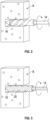
Figure 2 schematically illustrates use of the surgical system ofFigure 1 for preparing a hole in a bone. -
Figure 3 schematically illustrates use of the surgical system ofFigure 1 for implanting a surgical implant into a prepared bone. -
Figure 4 is a perspective view of an exemplary impact driver adaptor. -
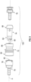
Figure 5 is an exploded view of the impact drive adaptor ofFigure 4 . -
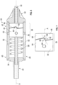
Figure 6 is a partial cross-sectional view of the impact driver adaptor ofFigure 4 . -
Figure 7 illustrates exemplary mating features of an engagement assembly of the impact driver adaptor ofFigure 4 . -
Figure 8 is a perspective view of another exemplary impact driver adaptor. -
Figure 9 is an exploded view of the impact drive adaptor ofFigure 8 . -
Figure 10 is a partial cross-sectional view of the impact driver adaptor ofFigure 8 . -
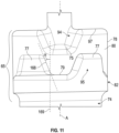
Figure 11 illustrates exemplary mating features of an engagement assembly of the impact driver adaptor ofFigure 8 . -
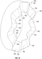
Figure 12 illustrates an exemplary engagement device that can be incorporated into an engagement assembly of an impact driver adaptor. - This disclosure is directed to surgical impact driver adaptors that may be connected between a powered surgical instrument and a driven surgical device when performing surgical procedures, such as those involving the implantation of a surgical implant into bone, for example. During surgical procedures, the surgical impact driver adaptors may limit a transfer of a rotational force from the powered surgical instrument to the surgical device until a sufficient axial force is applied to the impact driver adaptor from the powered surgical instrument. These and other features of this disclosure are described in further detail below.
- An exemplary surgical impact driver adaptor may include, inter alia, a first connector adapted to receive a rotational force, a second connector, and an outer locking sleeve that includes a proximal end portion configured to interface with a boss of the first connector and a distal end portion configured to interface with the second connector. An anvil coupling includes a proximal end portion received within an inner bore of the boss of the first connector. The anvil coupling is substantially housed within the boss and the outer locking sleeve. The boss of the first connector provides a hammer feature, and the proximal end portion of the anvil coupling provides an anvil feature that is configured to mate with and engage the hammer feature. A disengagement spring is configured to bias the anvil feature and the hammer feature apart, thereby disengaging the second connector from receiving the rotational force until an axial force that exceeds a predefined threshold is applied to the first connector
- Another exemplary impact driver adaptor may include, inter alia, a first connector adapted to receive a rotational force, a rotational component operably coupled to the first connector, and an engagement assembly configured to disengage the rotational component from receiving the rotational force until an axial force that exceeds a predefined threshold is applied to the first connector.
- In a further embodiment, a first connector of a surgical impact driver adaptor is configured to receive a rotational force from a powered surgical instrument.
- In a further embodiment, a rotational component of a surgical impact driver adaptor is configured to connect to a surgical device.
- In a further embodiment, a rotational component of a surgical impact drive adaptor is a drive shaft.
- In a further embodiment, a rotational component of a surgical impact driver adaptor is a second connector.
- In a further embodiment, an engagement assembly of a surgical impact driver adaptor includes a rear clutch cylinder, a front clutch cylinder, and a disengagement spring that is configured to bias the rear clutch cylinder and the front clutch cylinder apart until an axial force exceeds a predefined threshold.
- In a further embodiment, a rear clutch cylinder includes a first set of teeth that are configured to engage and mesh with a second set of teeth of a front clutch cylinder.
- In a further embodiment, a ramp is established at each location where a first set of teeth engage a second set of teeth.
- In a further embodiment, a rotational component of a surgical impact driver adaptor is a drive shaft that is fixedly secured to a front clutch cylinder and free to rotate relative to a rear clutch cylinder.
- In a further embodiment, a spring is arranged between a cap of a first connector and a rear clutch cylinder of a surgical impact driver adaptor. The spring is configured to dampen linear impact loads created by an axial force.
- In a further embodiment, an engagement assembly of a surgical impact driver adaptor includes a hammer feature provided by a first connector, an anvil feature provided by an anvil coupling, and a disengagement spring that is configured to bias the hammer feature and the anvil feature apart until an axial force exceeds a predefined threshold.
- In a further embodiment, a hammer feature includes a first set of teeth that are configured to engage and mesh with a second set of teeth of an anvil feature.
- In a further embodiment, a ramp is established at each location where a first set of teeth engage a second set of teeth.
- In a further embodiment, a rotational component of a surgical impact driver adaptor is a second connector that is operably coupled to an anvil coupling.
- In a further embodiment, a second connector of a surgical impact drive adaptor is a quick connect coupling.
- In a further embodiment, an engagement assembly of a surgical impact driver adaptor includes an engagement device having a wave disk configuration.
- An exemplary surgical method may include, inter alia, limiting a transfer of a rotational force from a powered surgical instrument to a surgical device until a sufficient axial force is applied to an impact driver adaptor from the powered surgical instrument during a surgical procedure.
- In a further embodiment, a powered surgical instrument utilized in a surgical method is a surgical drill.
- In a further embodiment, a surgical device utilized in a surgical method is a surgical drill bit or a surgical implant inserter.
-
Figure 1 schematically illustrates asurgical system 10 that can be utilized for performing various surgical procedures. For example, thesurgical system 10 may be used to prepare a bone for receiving a surgical implant, such as a suture anchor or an interference screw, and for implanting the surgical implant within the prepared bone. However, thesurgical system 10 may be utilized to perform various other surgical procedures within the scope of this disclosure. - The
surgical system 10 may include a poweredsurgical instrument 12 and asurgical device 14 that can be selectively driven (e.g., rotated) by the poweredsurgical instrument 12. In an embodiment, the poweredsurgical instrument 12 is a surgical drill that is configured to create axial and rotational forces for driving thesurgical device 14 during a surgical procedure. The axial forces may create linear impact loads and the rotational forces may create torque loads for driving thesurgical device 14. - In an embodiment, the
surgical device 14 is a drill bit that may be driven by the poweredsurgical instrument 12 in order to prepare ahole 18 in a bone B (seeFigure 2 ). The bone B could be any bone of the human musculoskeletal system. - In another embodiment, the
surgical device 14 is an implant inserter that may be driven by the poweredsurgical instrument 12 in order to implant asurgical implant 20 into thehole 18 formed in the bone B (seeFigure 3 ). Thesurgical implant 20 could be a suture anchor, an interference screw, or any other implantable surgical device. - The
surgical system 10 may additionally include animpact driver adaptor 22. Theimpact driver adaptor 22 may be connected between the poweredsurgical instrument 12 and thesurgical device 14 for transferring the axial and rotational forces created by the poweredsurgical instrument 12 to thesurgical device 14. As discussed in greater detail below, theimpact driver adaptor 22 may provide for a more controlled power transfer from the poweredsurgical instrument 12 to thesurgical device 14 by limiting the torque applied to thesurgical device 14 until an axial force of a sufficient threshold is applied from the poweredsurgical instrument 12 to theimpact driver adaptor 22. Material fatigue and implant insertion site morbidity may be reduced by controlling power transfer from the poweredsurgical instrument 12 to thesurgical device 14 in this way. -
Figures 4 ,5 , and6 illustrate an exemplaryimpact driver adaptor 22 that may be utilized as part of thesurgical system 10 ofFigure 1 . Theimpact driver adaptor 22 may include, among various other components, afirst connector 24, anouter sheath 26, anengagement assembly 28, adrive shaft 30, and afront cap 32. Theimpact driver adaptor 22 extends along a longitudinal axis A between a first orproximal portion 34 and a second ordistal portion 36. Thefirst connector 24 is located at theproximal portion 34 of theimpact driver adaptor 22, and a distal end of thedrive shaft 30 establish thedistal portion 36 of theimpact driver adaptor 22. The overall dimensions of theimpact driver adaptor 22 are not intended to limit this disclosure. - The
first connector 24 is configured for coupling theimpact driver adaptor 22 to the poweredsurgical instrument 12. In an embodiment, thefirst connector 24 is configured as a Hudson connector. However, other types of connectors are alternatively contemplated within the scope of this disclosure for coupling theimpact driver adaptor 22 to the poweredsurgical instrument 12. - The
outer sheath 26 may include a cylindrical, tubular body that extends between aproximal end portion 40 and adistal end portion 42. Acap 38 of thefirst connector 24 may be fixedly secured (e.g., welded, bonded, etc.) to theproximal end portion 40 of theouter sheath 26, and thefront cap 32 may be fixedly connected (e.g., welded, bonded, etc.) to thedistal end portion 42 of theouter sheath 26. When theimpact driver adaptor 22 is assembled, theengagement assembly 28 and portions of thedrive shaft 30 are substantially housed within theouter sheath 26, and thefront cap 32 axially constrains theengagement assembly 28 within theouter sheath 26. - The
first connector 24, theouter sheath 26, theengagement assembly 28, thedrive shaft 30, and thefront cap 32 may be coaxial relative to one another, and at least a portion of thedrive shaft 30 may be circumscribed by each of thefirst connector 24, theouter sheath 26, theengagement assembly 28, and thefront cap 32. Thedrive shaft 30 may extend entirely through theouter sheath 26 and thefront cap 32 to a location that is distally beyond thefront cap 32 for connecting to thesurgical device 14. Although not shown, thedrive shaft 30 could include a second connector, such as a quick connect device, for example, for coupling thesurgical device 14 to theimpact driver adaptor 22. - The
engagement assembly 28 may include a rearclutch cylinder 44, a frontclutch cylinder 46, and adisengagement spring 48. The rearclutch cylinder 44 may include one ormore pins 50 that may be received within correspondingslots 52 formed through theouter sheath 26. In an embodiment, fourpins 50 and fourcorresponding slots 52 may be provided. However, other configurations are also possible. The pin(s) 50 may slide within the slot(s) 52 to guide axial translation of the rearclutch cylinder 44 along the longitudinal axis A during use of theimpact driver adaptor 22 as part of thesurgical system 10. - The
drive shaft 30 may extend through the rearclutch cylinder 44 without being fixedly secured thereto. The rearclutch cylinder 44 is therefore free to rotate relative to thedrive shaft 30. The frontclutch cylinder 46 may be fixedly secured (e.g., welded or bonded) to thedrive shaft 30. - The disengagement spring 48 (best shown in
Figure 5 ) may be received about a portion of thedrive shaft 30 that is disposed between the rearclutch cylinder 44 and the frontclutch cylinder 46. Thedisengagement spring 48 may extend between respective bearing surfaces of the rearclutch cylinder 44 and the frontclutch cylinder 46 and is adapted to bias the rearclutch cylinder 44 in a direction away from the front clutch cylinder 46 (e.g., in the proximal direction) Therefore, in a default position of theimpact driver adaptor 22, thedrive shaft 30 is disengaged from arotational force 54 applied from the poweredsurgical instrument 12 until anaxial force 56 exceeding a predefined threshold is applied by the poweredsurgical instrument 12 for overcoming the biasing force of thedisengagement spring 48. Once the biasing force is overcome by theaxial force 56, the rearclutch cylinder 44 may engage the frontclutch cylinder 46 to begin rotating thedrive shaft 30. - In an embodiment, the
rotational force 54 is applied circumferentially about the longitudinal axis A, and theaxial force 56 is applied in a direction along the longitudinal axis A (seeFigure 4 ). Theaxial force 56 may alternatively be referred to as a normal force or a linear force. Theaxial force 56 may create a linear impact load for driving thesurgical device 14, and therotational force 54 may create a torque load for driving thesurgical device 14. - The
impact driver adaptor 22 may additionally include aspring 58. Thespring 58 is a separate component from thedisengagement spring 48 and may be housed within theouter sheath 26. Thespring 58 may be positioned between thecap 38 and the rearclutch cylinder 44, for example. Thespring 58 may function as a dampening mechanism for smoothing theaxial force 56 that is applied to theimpact driver adaptor 22 from the poweredsurgical instrument 12. Dampening linear impact loads in this manner provides the user with more control during operation, thereby reducing implant insertion site morbidity. - In an embodiment, the
disengagement spring 48 and thespring 58 are both coil springs. However, other types of springs may also be suitable and are further contemplated within the scope of this disclosure. - During uses of the
impact driver adaptor 22, the poweredsurgical instrument 12 may apply therotational force 54 to thefirst connector 24, thereby causing theouter sheath 26 and the rearclutch cylinder 44 to begin rotating about the longitudinal axis A. The frontclutch cylinder 46 and thedrive shaft 30 remain stationary at this stage of the operation. - As operation continues, the powered
surgical instrument 12 may begin applying theaxial force 56 to theimpact drive adaptor 22. Once theaxial force 56 exceeds a predefined threshold, the biasing force of thedisengagement spring 48 is overcome, thereby allowing the rearclutch cylinder 44 to engage the frontclutch cylinder 46 and thus begin rotating thedrive shaft 30. The rotational torque of thedrive shaft 30 may then begin driving thesurgical device 14. - The magnitude of the
axial force 56 necessary for overcoming the predefined threshold may vary depending on the desired application and could be between about 2 pounds (lbs.) and about 40 pounds (lbs.). In this disclosure, the term "about" means that the expressed quantities or ranges need not be exact but may be approximated and/or larger or smaller, reflecting acceptable tolerances, conversion factors, measurement error, etc. For example, theaxial force 56 could be about 2 lbs. when thesurgical device 14 is a drill bit, could be about 10 lbs. when thesurgical device 14 is a suture anchor inserter for inserting a PEEK/metallic suture anchor, or could be between about 20 lbs. and about 40 lbs. when thesurgical device 14 is a suture anchor inserter for inserting a biocomposite suture anchor. - The magnitude of the
axial force 56 may further depend on the drive mechanism used to connect thedrive shaft 30 to thesurgical device 14. For example, hexalobe drive mechanisms may provide a relatively low amount ofaxial force 56, hex drive mechanisms may provide a relatively large amount ofaxial force 56, and torx drive mechanisms may provide an amount ofaxial force 56 that is between that provided by the hexalobe and hex mechanisms. - Referring now primarily to
Figures 5-7 , theengagement assembly 28 of theimpact driver adaptor 22 may include mating features that allow the rearclutch cylinder 44 to engage the frontclutch cylinder 46 for rotating thedrive shaft 30. For example, the rearclutch cylinder 44 may include a first set ofteeth 60 that are dimensioned to engage and mesh with a second set ofteeth 62 of the frontclutch cylinder 46 for enabling rotation of thedrive shaft 30. The first set ofteeth 60 may be provided at an outercylindrical surface 64 of the rearclutch cylinder 44, and the second set ofteeth 62 may be provided at an outercylindrical surface 66 of the front clutch cylinder 46 (see, e.g.,Figure 7 ). - Each set of
teeth cylindrical surfaces impact driver adaptor 22. - The first and second set of
teeth - As best illustrated in
Figure 7 , aramp 68 may be established at each location where the first set ofteeth 60 engage the second set ofteeth 62. Eachramp 68 may extend at an angle α relative to anaxis 69 that is parallel to the longitudinal axis A. In an embodiment, the angle is α between about 2 degrees and about 60 degrees. In general, the lower the angle α of theramp 68, the higher the amount of torque that can be transferred by theimpact driver adaptor 22. Therefore, the angle α of theramp 68 is another factor that can vary depending on design specific parameters such as the desired torque limit of theimpact driver adaptor 22. - The actual amount of the angle α may vary depending on the amount of rotary impact that is desired for a specific application. For example, the angle α could be about 60 degrees (less rotation relative to axial impact) when drilling to create bone tunnels, could be about 10 degrees when inserting suture anchors of tougher materials (e.g., PEEK), could be about 2 degrees when inserting metallic suture anchors or interference screws, or could be about 30 degrees when inserting biocomposite suture anchors.
- The rotary impact transferred to the surgical device may further be controlled based on the drive mechanism used to connect the
drive shaft 30 to thesurgical device 14. For example, hexalobe drive mechanisms may provide a relatively high amount of rotary impact, hex drive mechanisms may provide a relatively low amount of rotary impact, and torx drive mechanisms may provide an amount of rotary impact that is between that provided by the hexalobe and hex mechanisms. -
Figures 8 ,9 , and10 illustrate another exemplaryimpact driver adaptor 122 that may be used as part of thesurgical system 10 ofFigure 1 . The design of theimpact driver adaptor 122 is structurally different from that of theimpact driver adaptor 22. Among other differences, theimpact driver adaptor 122 provides a smaller longitudinal footprint compared to theimpact driver adaptor 22. Nevertheless, like theimpact driver adaptor 22, theimpact driver adaptor 122 is configured to function to limit the torque applied to thesurgical device 14 until an axial force of a sufficient magnitude is applied from the poweredsurgical instrument 12 to theimpact driver adaptor 122. - The
impact driver adaptor 122 may include, among various other components, afirst connector 70, anouter locking sheath 72, ananvil coupling 74, and asecond connector 76. Theimpact driver adaptor 122 extends along a longitudinal axis A between a first orproximal portion 134 and a second ordistal portion 136. Thefirst connector 70 is located at theproximal portion 134 of theimpact driver adaptor 122, and thesecond connector 76 is located at thedistal portion 136 of theimpact driver adaptor 122. The overall dimensions of theimpact driver adaptor 122 are not intended to limit this disclosure. Thefirst connector 70, theouter locking sheath 72, theanvil coupling 74, and thesecond connector 76 may be arranged in a coaxial relationship relative to one another along the longitudinal axis A. - The
first connector 70 is configured for coupling theimpact driver adaptor 122 to the poweredsurgical instrument 12. In an embodiment, thefirst connector 70 is configured as a Hudson connector. However, other types of connectors are alternatively contemplated within the scope of this disclosure for coupling theimpact driver adaptor 122 to the poweredsurgical instrument 12. - The
second connector 76 is configured to coupling thesurgical device 14 to theimpact driver adaptor 122. In an embodiment, thesecond connector 76 is configured as a quick connect coupling. However, other types of connectors are alternatively contemplated within the scope of this disclosure for coupling thesurgical device 14 to theimpact driver adaptor 122. - The
first connector 70 may include aboss 78 having aninner bore 80. Theinner bore 80 may be sized to accommodate aproximal portion 82 of theanvil coupling 74. - The
outer locking sheath 72 may include a tapered cylindrical tubular body that extends between aproximal end portion 84 and adistal end portion 86. Theproximal end portion 84 is configured to interface with theboss 78 of thefirst connector 70, and thedistal end portion 86 is configured to interface with both adistal portion 88 of theanvil coupling 74 and thesecond connector 76. In an embodiment, theproximal end portion 84 of theouter locking sheath 72 is movably secured relative to theboss 78 of thefirst connector 70. When theimpact driver adaptor 122 is assembled, theanvil coupling 74 is substantially housed within theboss 78 of the first connector and theouter locking sheath 72. - A shaft 90 (see
Figure 9 ) may extend from theproximal portion 82 of theanvil coupling 74. Theshaft 90 may be received within a passage 92 (seeFigure 10 ) of thefirst connector 70. Thepassage 92 may connect to theinner bore 80. - A
hammer feature 94 may be provided by theboss 78 of thefirst connector 70. Thehammer feature 94 is configured to interface with acorresponding anvil feature 95 of theproximal portion 82 of theanvil coupling 74 for establishing an engagement assembly 65 (seeFigures 10-11 ) of theimpact driver adaptor 122. - A disengagement spring 96 (see
Figure 10 ) may be housed within theouter locking sleeve 72. Thedisengagement spring 96 may be positioned between adistal flange 98 of theboss 78 and aninner diameter flange 89 of theouter locking sleeve 72. Thedisengagement spring 96 may bias theanvil coupling 74 in a direction away from the hammer feature 94 (e.g., distally). Therefore, in a default position of theimpact driver adaptor 122, the anvil coupling 74 (and thus the second connector 76) is disengaged from arotational force 154 applied from the poweredsurgical instrument 12 to thefirst connector 70 until a sufficientaxial force 156 is applied by the poweredsurgical instrument 12 for overcoming the biasing force of thedisengagement spring 96. Once the biasing force is overcome by theaxial force 156, thehammer feature 94 may engage theanvil feature 95 and begin rotating the anvil coupling 74 (and thus thesecond connector 76 and any surgical device connected thereto). - In an embodiment, as best shown in
Figure 8 , therotational force 154 is applied circumferentially about the longitudinal axis A, and theaxial force 156 is applied in a direction along the longitudinal axis A. Theaxial force 156 may create a linear impact load for driving thesurgical device 14, and therotational force 154 may create a torque load for driving thesurgical device 14. - During use of the
impact driver adaptor 122, the poweredsurgical instrument 12 may apply therotational force 154 to thefirst connector 70, thereby rotating thefirst connector 70 about the longitudinal axis A relative to the other subcomponents of theimpact driver adaptor 122. Theouter locking sheath 72, theanvil coupling 74, and thesecond connector 76 each remain stationary at this stage of the operation. - As operation continues, the powered
surgical instrument 12 will begin applying theaxial force 156 to theimpact drive adaptor 122. Once theaxial force 156 exceeds a predefined threshold, the biasing force of thedisengagement spring 96 is overcome, thereby allowing theanvil coupling 74 to travel proximally and permit theanvil feature 95 and thehammer feature 94 to engage one another and begin rotating theanvil coupling 74. The rotational torque from the poweredsurgical instrument 12 may then be transferred through theanvil coupling 74 and thesecond connector 76 for driving thesurgical device 14. - Referring now primarily to
Figures 10-11 , thehammer feature 94 and theanvil feature 95 may each include mating features for allowing thefirst connector 70 and theanvil coupling 74 to operably engage one another. For example, thehammer feature 94 may include a first set ofteeth 75 that are dimensioned to engage and mesh with a second set ofteeth 77 of theanvil feature 95 for enabling rotation of theanvil coupling 74. The first set ofteeth 75 may protrude from afloor 97 of theboss 78, and the second set ofteeth 77 may protrude from aplanar face 79 of theproximal portion 82 of theanvil coupling 74. - Each set of
teeth teeth 75 may be circumferentially spaced from one another along a planar face established by thefloor 97, and the teeth of the second set ofteeth 77 may be circumferentially spaced from one another about theplanar face 79. The total number of teeth provided in each set 75, 77 may depend on various factors, including but not limited to the desired torque limit of theimpact driver adaptor 122. - A
ramp 168 is established at each location where the first set ofteeth 75 engage the second set ofteeth 77. Eachramp 168 may extend at an angle α relative to anaxis 169 that is substantially parallel to the longitudinal axis A. In an embodiment, the angle is α between about 2 degrees and about 60 degrees. In general, the lower the angle α of theramp 168, the higher the amount of torque that can be transferred by theimpact driver adaptor 122. Therefore, the angle α of theramp 168 is another factor that can vary depending on design specific parameters such as the desired torque limit of theimpact driver adaptor 122. -
Figure 12 illustrates anexemplary engagement device 100. Theengagement device 100 could be incorporated as part of theengagement assembly 28 of theimpact driver adaptor 22 or as part of theengagement assembly 65 of theimpact driver adaptor 122 for controlling the transfer of torque loads from a powered surgical instrument to a driven surgical device. - In an embodiment, the
engagement device 100 includes a wave disk design having a plurality of engageable features 102 (e.g., teeth). The engageable features 102 provide rampedengagement surfaces 104 adapted for engaging corresponding ramped surfaces of a second engagement device for transferring torque. The design of theengagement device 100 allows for a relatively low amount of torque to be applied relative to axial forces. The design of theengagement device 100 may be particularly suitable for driving certain types of drill bits, for example. - The impact driver adaptors of this disclosure advantageously provide ramped engagement of rotary loads when drilling or inserting surgical implants. The unique drive/engagement mechanisms discussed herein allow for disengagement of the driven surgical device until a desired axial load is achieved, thereby removing certain failure modes and material constraints. Further, the exemplary impact driver adaptors discussed herein exhibit self-dampening designs that absorb impact loads in a manner than can reduce implant insertion site morbidity.
- Although the different non-limiting embodiments are illustrated as having specific components or steps, the embodiments of this disclosure are not limited to those particular combinations. It is possible to use some of the components or features from any of the non-limiting embodiments in combination with features or components from any of the other non-limiting embodiments.
- It should be understood that like reference numerals identify corresponding or similar elements throughout the several drawings. It should further be understood that although a particular component arrangement is disclosed and illustrated in these exemplary embodiments, other arrangements could also benefit from the teachings of this disclosure.
- The foregoing description shall be interpreted as illustrative and not in any limiting sense. A worker of ordinary skill in the art would understand that certain modifications could come within the scope of this disclosure. For these reasons, the following claims should be studied to determine the true scope and content of this disclosure.
Claims (15)
- A surgical impact driver adaptor (22), comprising:a first connector (24) adapted to receive a rotational force (154);a second connector (76);an outer locking sleeve (72) including a proximal end portion (84) configured to interface with a boss (78) of the first connector (24) and a distal end portion (86) configured to interface with the second connector (76);an anvil coupling (74) including a proximal end portion (84) received within an inner bore (80) of the boss (78) of the first connector (24),wherein the anvil coupling (74) is substantially housed within the boss (78) and the outer locking sleeve (72);the boss (78) of the first connector (24) providing a hammer feature (94);the proximal end portion (84) of the anvil coupling (74) providing an anvil feature (95) configured to mate with and engage the hammer feature (94); anda disengagement spring (96) configured to bias the anvil feature (95) and the hammer feature (94) apart, thereby disengaging the second connector (76) from receiving the rotational force (154) until an axial force (156) that exceeds a predefined threshold is applied to the first connector (24).
- A surgical impact driver adaptor (22), comprising:a first connector (24) adapted to receive a rotational force (154);a rotational component operably coupled to the first connector (24); andan engagement assembly (28) configured to disengage the rotational component from receiving the rotational force (154) until an axial force (156) that exceeds a predefined threshold is applied to the first connector (24).
- The surgical impact driver adaptor (22) according to any of the previous claims, wherein the first connector (24) is configured to receive the rotational force (154) from a powered surgical instrument (12).
- The surgical impact driver adaptor (22) as recited in claim 2, wherein the rotational component is configured to connect to a surgical device (14) and wherein the rotational component may be a drive shaft (30) or a second connector (76).
- The surgical impact driver adaptor (22) according to any of the previous claims, wherein the engagement assembly (28) includes a rear clutch cylinder (44), a front clutch cylinder (46), and a disengagement spring (96) that is configured to bias the rear clutch cylinder (44) and the front clutch cylinder (46) apart until the axial force (156) exceeds the predefined threshold.
- The surgical impact driver adaptor (22) as recited in claim 5, wherein the rear clutch cylinder (44) includes a first set of teeth (75) that are configured to engage and mesh with a second set of teeth (77) of the front clutch cylinder (46).
- The surgical impact driver adaptor (22) as recited in claim 6, wherein a ramp is established at each location where the first set of teeth (75) engage the second set of teeth (77).
- The surgical impact driver adaptor (22) as recited in claim 5, wherein the rotational component is a drive shaft (30) that is fixedly secured to the front clutch cylinder (46) and free to rotate relative to the rear clutch cylinder (44).
- The surgical impact driver adaptor (22) as recited in claim 5, comprising a spring (58) arranged between a cap of the first connector (24) and the rear clutch cylinder (44), wherein the spring (58) is configured to dampen linear impact loads created by the axial force (156).
- The surgical impact driver adaptor (22) according to any of claims 2 to 9, wherein the engagement assembly (28) includes a hammer feature (94) provided by the first connector (24), an anvil feature (95) provided by an anvil coupling (74), and a disengagement spring (96) that is configured to bias the hammer feature (94) and the anvil feature (95) apart until the axial force (156) exceeds the predefined threshold.
- The surgical impact driver adaptor (22) as recited in claim 10, wherein the hammer feature (94) includes a first set of teeth (75) that are configured to engage and mesh with a second set of teeth (77) of the anvil feature (95).
- The surgical impact driver adaptor (22) as recited in claim 11, wherein a ramp is established at each location where the first set of teeth (75) engage the second set of teeth (77).
- The surgical impact driver adaptor (22) as recited in claim 10, wherein the rotational component is a second connector (76) that is operably coupled to the anvil coupling (74).
- The surgical impact driver adaptor (22) as recited in claim 13, wherein the second connector (76) is a quick connect coupling.
- The surgical impact driver adaptor (22) according to any of claims 2 to 14, wherein the engagement assembly (28) includes an engagement device (100) that includes a wave disk configuration.
Applications Claiming Priority (1)
| Application Number | Priority Date | Filing Date | Title |
|---|---|---|---|
| US17/669,684 US12201306B2 (en) | 2022-02-11 | 2022-02-11 | Surgical impact driver adaptors for applying directed torque and linear impact loads during surgical procedures |
Publications (1)
| Publication Number | Publication Date |
|---|---|
| EP4226880A1 true EP4226880A1 (en) | 2023-08-16 |
Family
ID=85225034
Family Applications (1)
| Application Number | Title | Priority Date | Filing Date |
|---|---|---|---|
| EP23156014.5A Pending EP4226880A1 (en) | 2022-02-11 | 2023-02-10 | Surgical impact driver adaptors for applying directed torque and linear impact loads during surgical procedures |
Country Status (2)
| Country | Link |
|---|---|
| US (2) | US12201306B2 (en) |
| EP (1) | EP4226880A1 (en) |
Citations (5)
| Publication number | Priority date | Publication date | Assignee | Title |
|---|---|---|---|---|
| BE498191A (en) * | 1949-09-28 | 1950-12-14 | American Screw Co | THRUST-TORQUE CONTROL DEVICE FOR ROTATING TOOLS |
| US20060016300A1 (en) * | 2003-09-10 | 2006-01-26 | Felo-Werkzeugfabrik Holland-Letz Gmbh | Screwdriver with adjustable device to limit transmitted torque |
| US20130048460A1 (en) * | 2011-08-11 | 2013-02-28 | Valentin Keller | Hand Machine Tool |
| US20170027594A1 (en) * | 2014-03-31 | 2017-02-02 | Mihaly Gyula Ujvari | Perforator |
| US20210219997A1 (en) * | 2020-01-16 | 2021-07-22 | Spinal Innovations, Llc | Pressure activated surgical tool for use in spinal decompression procedures and methods of using the same |
Family Cites Families (15)
| Publication number | Priority date | Publication date | Assignee | Title |
|---|---|---|---|---|
| US4362161A (en) * | 1980-10-27 | 1982-12-07 | Codman & Shurtleff, Inc. | Cranial drill |
| US5330480A (en) * | 1993-03-03 | 1994-07-19 | Codman & Shurtleff, Inc. | Surgical drill |
| JP2006315093A (en) | 2005-05-10 | 2006-11-24 | Hitachi Koki Co Ltd | Impact tools |
| US8021366B2 (en) * | 2005-07-11 | 2011-09-20 | Kyphon Sarl | Axial load limiting system and methods |
| US20090024129A1 (en) * | 2007-07-19 | 2009-01-22 | Jeremy Gordon | Perforator with inner and outer drills and a drive head, the inner drill configured to move against the outer drill in order to disengage from the drive head |
| US7762164B2 (en) * | 2008-06-02 | 2010-07-27 | Eca Medical Instruments | Torque-limiting device |
| JP5744639B2 (en) | 2011-06-17 | 2015-07-08 | 株式会社マキタ | Electric tool |
| US8757035B2 (en) * | 2011-12-20 | 2014-06-24 | Symmetry Medical, Inc. | Torque limiting ratchet device |
| DE102011089919A1 (en) | 2011-12-27 | 2013-06-27 | Robert Bosch Gmbh | Hand tool device |
| TWI437977B (en) * | 2011-12-28 | 2014-05-21 | Metal Ind Res & Dev Ct | Apparatus for maxillary sinus operation |
| KR101515883B1 (en) | 2013-12-19 | 2015-05-04 | 계양전기 주식회사 | Control apparatus of impact power tools |
| JP6354978B2 (en) | 2014-03-27 | 2018-07-11 | 勝行 戸津 | Torque limiter in constant torque electric screwdriver |
| EP3538322A1 (en) | 2016-11-11 | 2019-09-18 | Zimmer Biomet Spine, Inc. | Tool torque limiter |
| DE102018118196A1 (en) | 2018-07-27 | 2020-01-30 | Festool Gmbh | Hand machine tools, in particular impact wrenches |
| DE102020113683A1 (en) | 2020-05-20 | 2021-11-25 | Adolf Würth GmbH & Co. KG | Bit holder with shock load protection device |
-
2022
- 2022-02-11 US US17/669,684 patent/US12201306B2/en active Active
-
2023
- 2023-02-10 EP EP23156014.5A patent/EP4226880A1/en active Pending
-
2024
- 2024-12-13 US US18/980,274 patent/US20250107811A1/en active Pending
Patent Citations (5)
| Publication number | Priority date | Publication date | Assignee | Title |
|---|---|---|---|---|
| BE498191A (en) * | 1949-09-28 | 1950-12-14 | American Screw Co | THRUST-TORQUE CONTROL DEVICE FOR ROTATING TOOLS |
| US20060016300A1 (en) * | 2003-09-10 | 2006-01-26 | Felo-Werkzeugfabrik Holland-Letz Gmbh | Screwdriver with adjustable device to limit transmitted torque |
| US20130048460A1 (en) * | 2011-08-11 | 2013-02-28 | Valentin Keller | Hand Machine Tool |
| US20170027594A1 (en) * | 2014-03-31 | 2017-02-02 | Mihaly Gyula Ujvari | Perforator |
| US20210219997A1 (en) * | 2020-01-16 | 2021-07-22 | Spinal Innovations, Llc | Pressure activated surgical tool for use in spinal decompression procedures and methods of using the same |
Also Published As
| Publication number | Publication date |
|---|---|
| US12201306B2 (en) | 2025-01-21 |
| US20230255645A1 (en) | 2023-08-17 |
| US20250107811A1 (en) | 2025-04-03 |
Similar Documents
| Publication | Publication Date | Title |
|---|---|---|
| EP3678564B1 (en) | Modular surgical instruments | |
| RU2648227C2 (en) | Surgical, torque-transmitting instrument including associated tool | |
| RU2671938C2 (en) | Surgical, torque-transmitting instrument including associated tool | |
| AU762547B2 (en) | Angularly adjustable powered surgical handpiece | |
| EP2988679B1 (en) | Dynamic locking device | |
| US20090306719A1 (en) | Structure and method for driving a pedicle screw with an attached support rod for spinal osteosynthesis | |
| EP2431008B1 (en) | Implant positioning system | |
| US9066730B2 (en) | Medical device | |
| RU2641837C2 (en) | Surgical device, transmitting torque, containing tool connected thereto | |
| EP4013317B1 (en) | Drill assembly for preparation of surgical sites | |
| US20230263641A1 (en) | Inserter guide and driver system | |
| KR20190046915A (en) | Multiple connection drive shaft | |
| US12201306B2 (en) | Surgical impact driver adaptors for applying directed torque and linear impact loads during surgical procedures | |
| EP1279373A2 (en) | Screwdriver used with a bone connector plate | |
| US12514594B2 (en) | Surgical attachments for a surgical handpiece system | |
| US20120059385A1 (en) | Variable angle depth limited fastener driver and variable angle fixation system for use in orthopedic plates | |
| JP6261592B2 (en) | Surgical torque transmission instrument including related tools | |
| AU2020300605B2 (en) | Automated anchor insertion system | |
| US20250255618A1 (en) | Surgical Handpiece System For Driving Surgical Pins And Related Accessories | |
| CN217886172U (en) | Adapter assembly, adapter kit and implantation instrument | |
| AU2012201198A1 (en) | Drive shaft for a surgical instrument |
Legal Events
| Date | Code | Title | Description |
|---|---|---|---|
| PUAI | Public reference made under article 153(3) epc to a published international application that has entered the european phase |
Free format text: ORIGINAL CODE: 0009012 |
|
| STAA | Information on the status of an ep patent application or granted ep patent |
Free format text: STATUS: THE APPLICATION HAS BEEN PUBLISHED |
|
| AK | Designated contracting states |
Kind code of ref document: A1 Designated state(s): AL AT BE BG CH CY CZ DE DK EE ES FI FR GB GR HR HU IE IS IT LI LT LU LV MC ME MK MT NL NO PL PT RO RS SE SI SK SM TR |
|
| STAA | Information on the status of an ep patent application or granted ep patent |
Free format text: STATUS: REQUEST FOR EXAMINATION WAS MADE |
|
| 17P | Request for examination filed |
Effective date: 20240216 |
|
| RBV | Designated contracting states (corrected) |
Designated state(s): AL AT BE BG CH CY CZ DE DK EE ES FI FR GB GR HR HU IE IS IT LI LT LU LV MC ME MK MT NL NO PL PT RO RS SE SI SK SM TR |
|
| STAA | Information on the status of an ep patent application or granted ep patent |
Free format text: STATUS: EXAMINATION IS IN PROGRESS |
|
| 17Q | First examination report despatched |
Effective date: 20251209 |