EP4226873B1 - Shock wave device with motion compensation - Google Patents
Shock wave device with motion compensation Download PDFInfo
- Publication number
- EP4226873B1 EP4226873B1 EP22155802.6A EP22155802A EP4226873B1 EP 4226873 B1 EP4226873 B1 EP 4226873B1 EP 22155802 A EP22155802 A EP 22155802A EP 4226873 B1 EP4226873 B1 EP 4226873B1
- Authority
- EP
- European Patent Office
- Prior art keywords
- shock wave
- patient
- tilt
- wave device
- movement
- Prior art date
- Legal status (The legal status is an assumption and is not a legal conclusion. Google has not performed a legal analysis and makes no representation as to the accuracy of the status listed.)
- Active
Links
Images


Classifications
-
- A—HUMAN NECESSITIES
- A61—MEDICAL OR VETERINARY SCIENCE; HYGIENE
- A61B—DIAGNOSIS; SURGERY; IDENTIFICATION
- A61B17/00—Surgical instruments, devices or methods
- A61B17/22—Implements for squeezing-off ulcers or the like on inner organs of the body; Implements for scraping-out cavities of body organs, e.g. bones; for invasive removal or destruction of calculus using mechanical vibrations; for removing obstructions in blood vessels, not otherwise provided for
- A61B17/225—Implements for squeezing-off ulcers or the like on inner organs of the body; Implements for scraping-out cavities of body organs, e.g. bones; for invasive removal or destruction of calculus using mechanical vibrations; for removing obstructions in blood vessels, not otherwise provided for for extracorporeal shock wave lithotripsy [ESWL], e.g. by using ultrasonic waves
-
- A—HUMAN NECESSITIES
- A61—MEDICAL OR VETERINARY SCIENCE; HYGIENE
- A61B—DIAGNOSIS; SURGERY; IDENTIFICATION
- A61B17/00—Surgical instruments, devices or methods
- A61B17/22—Implements for squeezing-off ulcers or the like on inner organs of the body; Implements for scraping-out cavities of body organs, e.g. bones; for invasive removal or destruction of calculus using mechanical vibrations; for removing obstructions in blood vessels, not otherwise provided for
- A61B17/225—Implements for squeezing-off ulcers or the like on inner organs of the body; Implements for scraping-out cavities of body organs, e.g. bones; for invasive removal or destruction of calculus using mechanical vibrations; for removing obstructions in blood vessels, not otherwise provided for for extracorporeal shock wave lithotripsy [ESWL], e.g. by using ultrasonic waves
- A61B17/2255—Means for positioning patient, shock wave apparatus or locating means, e.g. mechanical aspects, patient beds, support arms or aiming means
-
- A—HUMAN NECESSITIES
- A61—MEDICAL OR VETERINARY SCIENCE; HYGIENE
- A61B—DIAGNOSIS; SURGERY; IDENTIFICATION
- A61B17/00—Surgical instruments, devices or methods
- A61B17/22—Implements for squeezing-off ulcers or the like on inner organs of the body; Implements for scraping-out cavities of body organs, e.g. bones; for invasive removal or destruction of calculus using mechanical vibrations; for removing obstructions in blood vessels, not otherwise provided for
- A61B17/225—Implements for squeezing-off ulcers or the like on inner organs of the body; Implements for scraping-out cavities of body organs, e.g. bones; for invasive removal or destruction of calculus using mechanical vibrations; for removing obstructions in blood vessels, not otherwise provided for for extracorporeal shock wave lithotripsy [ESWL], e.g. by using ultrasonic waves
- A61B17/2256—Implements for squeezing-off ulcers or the like on inner organs of the body; Implements for scraping-out cavities of body organs, e.g. bones; for invasive removal or destruction of calculus using mechanical vibrations; for removing obstructions in blood vessels, not otherwise provided for for extracorporeal shock wave lithotripsy [ESWL], e.g. by using ultrasonic waves with means for locating or checking the concrement, e.g. X-ray apparatus, imaging means
-
- A—HUMAN NECESSITIES
- A61—MEDICAL OR VETERINARY SCIENCE; HYGIENE
- A61B—DIAGNOSIS; SURGERY; IDENTIFICATION
- A61B17/00—Surgical instruments, devices or methods
- A61B2017/00017—Electrical control of surgical instruments
-
- A—HUMAN NECESSITIES
- A61—MEDICAL OR VETERINARY SCIENCE; HYGIENE
- A61B—DIAGNOSIS; SURGERY; IDENTIFICATION
- A61B17/00—Surgical instruments, devices or methods
- A61B2017/00017—Electrical control of surgical instruments
- A61B2017/00022—Sensing or detecting at the treatment site
- A61B2017/00075—Motion
-
- A—HUMAN NECESSITIES
- A61—MEDICAL OR VETERINARY SCIENCE; HYGIENE
- A61B—DIAGNOSIS; SURGERY; IDENTIFICATION
- A61B17/00—Surgical instruments, devices or methods
- A61B2017/00681—Aspects not otherwise provided for
- A61B2017/00694—Aspects not otherwise provided for with means correcting for movement of or for synchronisation with the body
- A61B2017/00699—Aspects not otherwise provided for with means correcting for movement of or for synchronisation with the body correcting for movement caused by respiration, e.g. by triggering
Definitions
- a device and a method for localizing stones and for targeting a shock wave source of a lithotripter is disclosed in EP 2 340 781 A1 .
- a shockwave generator, a patient table and an ultrasound targeting device are provided with optical markers for tracking with a pair of infrared cameras.
- the body or parts of the body of a patient move slightly during breathing. This causes kidneys and other organs to move slightly such that they may move out of the focal volume of a shock wave source.
- DE 36 21 935 discloses a lithotripter which is synchronized to the signal of a respiration sensor. This allows only for short treatment periods with a comparatively low repetition frequency corresponding to the respiration frequency.
- EP 2 628 456 A1 discloses a shock wave therapy device with dynamic target tracking.
- US 2016/0114194 A1 discloses an optimized therapeutic energy delivery.
- the problem to be solved by the invention is to provide a shock wave device, which allows treatment of organs or areas within organs independent of respiration.
- the shock wave device should be comparatively simple and avoid complex and expensive mechanics.
- a shock wave device which may be a lithotripter includes a shock wave source and may further include a patient table.
- the shock wave source may be of any type suitable for generating shock waves. It may include a shock wave generator and/or transducer, which may include at least one of a coil, a spark gap or a Piezo transducer.
- the shock wave generator/transducer may be partially enclosed by a reflector. Depending on the type of transducer, the reflector may have a parabolic or half-elliptic shape.
- the shock wave source may have a focal volume which is distant from the shock wave source and normally around a center axis of the shock wave source.
- the focal volume may be defined as a volume, where the maximum shock wave intensity is maintained with a deviation of maximal -3 dB or -6 dB. If the focal volume is defined with a 6 dB deviation, the pressure at the limit of the zone is half of the maximum pressure inside the zone.
- the focal volume may have an elliptical shape with a length in an axial direction (defined by the center axis) of the shock wave source axis of 10 to 15 cm and a diameter between 5 and 15 mm. The focal volume normally is spaced from the shock wave generator and/or transducer.
- the patient table may have a basically planar surface defining a longitudinal axis. It is configured for accommodating a patient.
- the shock wave source may be mounted below the patient table. In general, a shockwave source may be mounted in alternative ways, e.g. on a stand or support.
- an object to be treated may move out of the focal volume.
- a movement of the chest causes a movement of the kidneys in a cranio-caudal direction, which is approximately parallel to the surface of the patient table accommodating the patient.
- the amplitude of displacement of the kidneys normally is in the range of 20 to 40 mm.
- the center axis of a normal shock wave generator is approximately orthogonal to the surface of the patient table, a kidney stone may easily move out of the focal volume.
- the respiration frequency of an anesthetized person may be in the range of 0.3 to 0.5 Hz.
- a shock wave source is arranged tiltable around at least one tilt axis which may be approximately parallel to a plane defined by a surface of a patient table, where a deviation in parallelism may be of +/- 30°. Further, the tilt axis may be orthogonal to a longitudinal axis of the patient table, where deviation in orthogonality of +/- 30° may be possible.
- the maximum angle of tilt may be in a range between 1° and 20°. It may be in a range between 1° and 10° or between 2° and 5°. A number of tests have shown that a typical angle of 2° is sufficient to track typical stone movements, whereas for larger movements an angle of 4° may be sufficient.
- Tilting of the shock wave source may be achieved by tilting the whole shock wave source including the shock wave generator/transducer and the reflector or only by tilting the shock wave generator/transducer. Tilting may be done by a tilting motor or a tilting drive, which may be a linear drive or any other suitable means. Tilting is synchronized to the motion of the patient body, which may be sensed by a motion sensor or by a respiration sensor.
- a respiration sensor may be a sensor configured for at least one of a chest movement of the patient due to respiration, a change of chest volume and/or size of the patient due to respiration, a change of position of an internal organ like kidney or heart by using ultrasound-imaging, a change of center of gravity of the patient and/or organ of interest which may be a kidney to be treated.
- a respiration sensor may be called a respiration sensor.
- the signal of the movement sensor/respiration sensor may be amplified with a variable gain. Further, an offset may be added to generate a tilt control signal defining the tilt angle. By this, a coupling of the tilt angle to the body movement and therefore to the movement of the kidney stone may be achieved.
- respiration and heartbeat may be considered. This may require a tilting movement about two different axes with different frequencies. Basically all parts of a body may be treated by compensating any movement by a tilting movement.
- a fine adjustment of the amplitude of the tilting movement may either be made manually by a user who may watch the imaging system and an indication of the focal volume. Further, adjustment of the amplitude may be made automatically, for example by a computer system, analyzing the images of the imaging system.
- a display may be provided indicating an image from an imaging system, like an x-ray image or and ultrasound image, which may further indicate the focal volume. Based on this, a user may estimate the quality of adjustment and treatment.
- any shock wave repetition frequency may be selected independent of the respiration frequency.
- the shock wave source may be rotated around the center axis about an angle in a range between +/- 2° to +/- 20°.
- the range may be between +/- 5° and +/- 15°.
- a range of +/-10° would meet most requirements.
- kidneys and kidney stones have a slightly outward movement in addition to the movement parallel to the patient table, which may be compensated by such a rotation around the center axis.
- there may be only two discrete angle settings for example at + 10° and at - 10°, one for the left kidney and the other for the right kidney, which would suit most patients.
- a larger number of positions may be provided.
- a drive like a motor may be provided to adjust the angle.
- kidney stone may also be applied to a urethra stone or other concrements in a body.
- the shock wave device or lithotripter may also include a linear drive for the shock wave source, which may be operating in 1, 2 or 3 axes. Such a drive may be used for general adjustment of the relative position of the shock wave source relative to the patient.
- a method of focusing a shock wave source to a kidney stone comprises the steps of:
- the tilt axis may be an axis in a plane essentially parallel to a plane of a patient table and essentially orthogonal to a longitudinal axis of the patient table, including deviations in parallelism and/or orthogonality of +/- 30°.
- the method may further include the steps of rotating the shock wave source around its center axis or a fixed angle before performing the steps a to c.
- a shock wave device which may be a lithotripter 100 may include a patient table 110 and a shock wave source 120.
- the shock wave source 120 may be arranged below the patient table 110, such that a patient (not shown here) may be accommodated on top of the patient table.
- the patient table may have a longitudinal axis 112. There may be a hole or cutout in the patient table at the position of the shock wave source.
- the shock wave source 120 may be tiltable in a direction of tilt 132 around a tilt axis 130.
- the shock wave source may be held by a tilt shaft 131 and operated by a tilt drive motor 142.
- a linear tilt drive 140 may be provided and configured for a linear movement in a linear tilt drive direction 141 to perform a tilt of the shock wave source 120.
- any kind of suspension and drive may be used, as long, as a tilt may be performed.
- This may also be a tripod drive.
- the shock wave source 120 may have a center axis 150, and it may be rotatable in a rotation direction 151 around the center axis 150.
- FIG. 2 shows a side view.
- a patient 800 is positioned on top of the patient table 110.
- the patient may have a kidney 810 with a kidney stone 820.
- the shock wave source 120 is shown in a sectional view. It may have a shock wave generator 128 which may be a coil as shown herein and which is at least partially enclosed by a reflector 129.
- the center axis 150 is marked as a dashed line and a tilted center axis 160 of a tilted state of the shock wave source is marked as a second dashed line.
- the interior of the reflector and the space between the source and the patient is filled with a liquid like water or another shockwave conducting medium.
- a coupling bellow 125 may be provided.
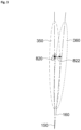
- Figure 3 shows focal volume positions with tilting in a side view.
- a first focal volume 350 is shown around the center axis 150 in a first state.
- this focal volume is displaced to second focal volume 360 around a tilted center axis 160.
- a tilt angle of approximately 4° is shown.
- a kidney stone 820 which may be centered to the center axis 150 in a first state, may move by respiration movement in a direction 822 to a second position, which then may be close to the tilted center axis 160.
- the kidney stone is always approximately at the center axis of the shock wave source and therefore within the focal volume. This ensures a high energy coupling into the stone at any time.
- Figure 4 shows a top view.
- the shock wave source may be rotated around the center axis 150 in a first direction, such that the tilt results in movement in a first tilt direction 311 under an angle to the longitudinal axis 112.
- the shock wave source may be rotated into an opposing second position, resulting in a tilting movement in a second tilt direction 321.
- the focal volume covered during the tilt movement is indicated with reference number 310 for the first tilt direction 311 and with reference number 320 for the second tilt direction 321.
- FIG. 5 shows a block diagram.
- a respiration sensor 410 produces a respiration signal or a signal related to respiration.
- a respiration signal may be a signal indicating the air flow into the body and/or out of the body, and/or a signal related to a movement of the body.
- a sensor measuring the circumference of the chest may be used to generate a signal for such an indication.
- the signal is coupled into a signal amplifier 420 which may further receive a gain signal 422 and an offset signal 424.
- the gain signal and the offset signal may either be manually set by an operator and/or may be set by a controller/computer 460. This signal allows to modify the amplitude of the signal received by the respiration sensor and to add an offset if desired.
- the output signal of the signal amplifier 420 may be fed to a computer/controller 460. It may also be fed to a motor controller 430 which generates a control signal for a tilt motor 440.
- the tilt motor 440 may tilt the shock wave source around the tilt axis 130. As mentioned above, it may be a rotating motor or a linear drive, depending on the mechanical design. In an embodiment, there may be a linear relationship between the input signal into the motor controller 430 and the tilt angle, further resulting in a linear relationship between the respiration sensor signal and the tilt angle. To prevent excessive tilt angles, the motor controller 430 and/or the signal amplifier 420 may have a limiter to limit the output signal.
- the controller/computer 460 may also receive a signal from an imaging system 450 which may be used to evaluate the position of the kidney stone.
- the controller/computer 460 may further be connected to a display 470 at which it may display an image from the imaging system 450 and/or an indication of the focal volume.
- the focal volume may be displayed in the same image, thus giving an indication of the overlapping of the focal volume with the kidney stone. This would allow to manually adjust the gain signal 422 and the offset signal 424 for best matching during respiration of the patient.
- the controller/computer 460 may also be connected to the motor controller 430 to control the motor e.g. based on the respiration sensor signal and/or a stone position derived from an image.
Landscapes
- Health & Medical Sciences (AREA)
- Surgery (AREA)
- Life Sciences & Earth Sciences (AREA)
- Nuclear Medicine, Radiotherapy & Molecular Imaging (AREA)
- Heart & Thoracic Surgery (AREA)
- Vascular Medicine (AREA)
- Engineering & Computer Science (AREA)
- Biomedical Technology (AREA)
- Orthopedic Medicine & Surgery (AREA)
- Medical Informatics (AREA)
- Molecular Biology (AREA)
- Animal Behavior & Ethology (AREA)
- General Health & Medical Sciences (AREA)
- Public Health (AREA)
- Veterinary Medicine (AREA)
- Radiology & Medical Imaging (AREA)
- Surgical Instruments (AREA)
Description
- The invention relates to an extracorporeal shock wave therapy system, e.g. a lithotripsy system or Lithotripter for non-invasive treatment of stones, like e.g. kidney stones, urinary stones, gallstones or other calculi within a mammal's body using acoustic pulses, or other applications of an extracorporeal shock wave therapy system where the treatment area is in motion during treatment.
- A device and a method for localizing stones and for targeting a shock wave source of a lithotripter is disclosed in
EP 2 340 781 A1 . Here a shockwave generator, a patient table and an ultrasound targeting device are provided with optical markers for tracking with a pair of infrared cameras. The body or parts of the body of a patient move slightly during breathing. This causes kidneys and other organs to move slightly such that they may move out of the focal volume of a shock wave source. -
DE 36 21 935 discloses a lithotripter which is synchronized to the signal of a respiration sensor. This allows only for short treatment periods with a comparatively low repetition frequency corresponding to the respiration frequency. -
EP 2 628 456 A1 discloses a shock wave therapy device with dynamic target tracking.US 2016/0114194 A1 discloses an optimized therapeutic energy delivery. - The problem to be solved by the invention is to provide a shock wave device, which allows treatment of organs or areas within organs independent of respiration. The shock wave device should be comparatively simple and avoid complex and expensive mechanics.
- Solutions of the problem are described in the independent claim.
- The dependent claims relate to further improvements of the invention.
- In an embodiment, a shock wave device, which may be a lithotripter includes a shock wave source and may further include a patient table. The shock wave source may be of any type suitable for generating shock waves. It may include a shock wave generator and/or transducer, which may include at least one of a coil, a spark gap or a Piezo transducer. The shock wave generator/transducer may be partially enclosed by a reflector. Depending on the type of transducer, the reflector may have a parabolic or half-elliptic shape. The shock wave source may have a focal volume which is distant from the shock wave source and normally around a center axis of the shock wave source. The focal volume may be defined as a volume, where the maximum shock wave intensity is maintained with a deviation of maximal -3 dB or -6 dB. If the focal volume is defined with a 6 dB deviation, the pressure at the limit of the zone is half of the maximum pressure inside the zone. The focal volume may have an elliptical shape with a length in an axial direction (defined by the center axis) of the shock wave source axis of 10 to 15 cm and a diameter between 5 and 15 mm. The focal volume normally is spaced from the shock wave generator and/or transducer.
- The patient table may have a basically planar surface defining a longitudinal axis. It is configured for accommodating a patient. The shock wave source may be mounted below the patient table. In general, a shockwave source may be mounted in alternative ways, e.g. on a stand or support.
- Due to movements of a patient's body, e.g. by respiration or heartbeat, an object to be treated may move out of the focal volume. For example, a movement of the chest causes a movement of the kidneys in a cranio-caudal direction, which is approximately parallel to the surface of the patient table accommodating the patient. The amplitude of displacement of the kidneys normally is in the range of 20 to 40 mm. As the center axis of a normal shock wave generator is approximately orthogonal to the surface of the patient table, a kidney stone may easily move out of the focal volume. The respiration frequency of an anesthetized person may be in the range of 0.3 to 0.5 Hz.
- In an embodiment, a shock wave source is arranged tiltable around at least one tilt axis which may be approximately parallel to a plane defined by a surface of a patient table, where a deviation in parallelism may be of +/- 30°. Further, the tilt axis may be orthogonal to a longitudinal axis of the patient table, where deviation in orthogonality of +/- 30° may be possible. The maximum angle of tilt may be in a range between 1° and 20°. It may be in a range between 1° and 10° or between 2° and 5°. A number of tests have shown that a typical angle of 2° is sufficient to track typical stone movements, whereas for larger movements an angle of 4° may be sufficient. Tilting of the shock wave source may be achieved by tilting the whole shock wave source including the shock wave generator/transducer and the reflector or only by tilting the shock wave generator/transducer. Tilting may be done by a tilting motor or a tilting drive, which may be a linear drive or any other suitable means. Tilting is synchronized to the motion of the patient body, which may be sensed by a motion sensor or by a respiration sensor. A respiration sensor may be a sensor configured for at least one of a chest movement of the patient due to respiration, a change of chest volume and/or size of the patient due to respiration, a change of position of an internal organ like kidney or heart by using ultrasound-imaging, a change of center of gravity of the patient and/or organ of interest which may be a kidney to be treated. Herein, for simplicity, such a sensor may be called a respiration sensor. The signal of the movement sensor/respiration sensor may be amplified with a variable gain. Further, an offset may be added to generate a tilt control signal defining the tilt angle. By this, a coupling of the tilt angle to the body movement and therefore to the movement of the kidney stone may be achieved.
- As the position of the focal volume moves in synchronicity with the kidney stone, generating of shock wave pulses at any time will result in a high energy coupling into the stone and a high treatment efficiency.
- For heart treatment, respiration and heartbeat may be considered. This may require a tilting movement about two different axes with different frequencies. Basically all parts of a body may be treated by compensating any movement by a tilting movement.
- A fine adjustment of the amplitude of the tilting movement may either be made manually by a user who may watch the imaging system and an indication of the focal volume. Further, adjustment of the amplitude may be made automatically, for example by a computer system, analyzing the images of the imaging system.
- A display may be provided indicating an image from an imaging system, like an x-ray image or and ultrasound image, which may further indicate the focal volume. Based on this, a user may estimate the quality of adjustment and treatment.
- Due to the body movement or respiration tracking of the shock wave source, any shock wave repetition frequency, may be selected independent of the respiration frequency.
- Due to the simple tilting movement of the shock wave source, only one movable axis is required, keeping the systems comparatively simple and efficient.
- In an embodiment, the shock wave source may be rotated around the center axis about an angle in a range between +/- 2° to +/- 20°. The range may be between +/- 5° and +/- 15°. In a typical application, a range of +/-10° would meet most requirements. Usually, kidneys and kidney stones have a slightly outward movement in addition to the movement parallel to the patient table, which may be compensated by such a rotation around the center axis. In a very simple embodiment, there may be only two discrete angle settings, for example at + 10° and at - 10°, one for the left kidney and the other for the right kidney, which would suit most patients. In another embodiment, a larger number of positions may be provided. Alternately, a drive like a motor may be provided to adjust the angle.
- The basic concept explains herein at the example of a kidney stone may also be applied to a urethra stone or other concrements in a body.
- The shock wave device or lithotripter may also include a linear drive for the shock wave source, which may be operating in 1, 2 or 3 axes. Such a drive may be used for general adjustment of the relative position of the shock wave source relative to the patient.
- The methods of operation disclosed are not explicitly recited by the wording of the claims but are considered useful for understanding the invention.
- A method of focusing a shock wave source to a kidney stone comprises the steps of:
- a) receiving a respiration signal indicative of a respiration,
- b) amplifying the signal and optionally adding an offset,
- c) tilting a shock wave source about an angle proportional to the signal.
- The tilt axis may be an axis in a plane essentially parallel to a plane of a patient table and essentially orthogonal to a longitudinal axis of the patient table, including deviations in parallelism and/or orthogonality of +/- 30°.
- The method may further include the steps of rotating the shock wave source around its center axis or a fixed angle before performing the steps a to c.
- In the following the invention will be described by way of example, without limitation of the general inventive concept, on examples of embodiment with reference to the drawings.
-
Figure 1 shows an embodiment. -
Figure 2 shows a side view. -
Figure 3 shows focal volume positions with tilting. -
Figure 4 shows a top view. -
Figure 5 shows a block diagram. - In
Figure 1 , a first embodiment is shown. A shock wave device, which may be alithotripter 100 may include a patient table 110 and ashock wave source 120. Theshock wave source 120 may be arranged below the patient table 110, such that a patient (not shown here) may be accommodated on top of the patient table. The patient table may have alongitudinal axis 112. There may be a hole or cutout in the patient table at the position of the shock wave source. Theshock wave source 120 may be tiltable in a direction oftilt 132 around atilt axis 130. The shock wave source may be held by atilt shaft 131 and operated by atilt drive motor 142. In another embodiment, alinear tilt drive 140 may be provided and configured for a linear movement in a lineartilt drive direction 141 to perform a tilt of theshock wave source 120. Basically, any kind of suspension and drive may be used, as long, as a tilt may be performed. This may also be a tripod drive. Further, theshock wave source 120 may have acenter axis 150, and it may be rotatable in arotation direction 151 around thecenter axis 150. -
Figure 2 shows a side view. In this figure, apatient 800 is positioned on top of the patient table 110. The patient may have akidney 810 with akidney stone 820. Below the table 110, theshock wave source 120 is shown in a sectional view. It may have a shock wave generator 128 which may be a coil as shown herein and which is at least partially enclosed by areflector 129. Further, thecenter axis 150 is marked as a dashed line and a tiltedcenter axis 160 of a tilted state of the shock wave source is marked as a second dashed line. Normally, the interior of the reflector and the space between the source and the patient is filled with a liquid like water or another shockwave conducting medium. To contain the water within the volume, acoupling bellow 125 may be provided. -
Figure 3 shows focal volume positions with tilting in a side view. On the left side, a firstfocal volume 350 is shown around thecenter axis 150 in a first state. When tilting the shock wave source about an angle, this focal volume is displaced to secondfocal volume 360 around a tiltedcenter axis 160. In this figure, a tilt angle of approximately 4° is shown. It can be seen that the first focal volume from a normal state and the second focal volume from a tilted state together cover roughly twice the volume at the center of the focal volumes. Akidney stone 820, which may be centered to thecenter axis 150 in a first state, may move by respiration movement in adirection 822 to a second position, which then may be close to the tiltedcenter axis 160. As the tilt of the shock wave source is synchronized with the respiration movement and therefore with the movement of thekidney 810 and with the movement of thekidney stone 820, the kidney stone is always approximately at the center axis of the shock wave source and therefore within the focal volume. This ensures a high energy coupling into the stone at any time. -
Figure 4 shows a top view. As the kidneys not only move roughly parallel to thelongitudinal axis 112 of the body and therefore of the patient table, but also move slightly sidewards, the shock wave source may be rotated around thecenter axis 150 in a first direction, such that the tilt results in movement in afirst tilt direction 311 under an angle to thelongitudinal axis 112. Alternatively, the shock wave source may be rotated into an opposing second position, resulting in a tilting movement in asecond tilt direction 321. The focal volume covered during the tilt movement is indicated withreference number 310 for thefirst tilt direction 311 and withreference number 320 for thesecond tilt direction 321. -
Figure 5 shows a block diagram. Arespiration sensor 410 produces a respiration signal or a signal related to respiration. Such a respiration signal may be a signal indicating the air flow into the body and/or out of the body, and/or a signal related to a movement of the body. For example, a sensor measuring the circumference of the chest may be used to generate a signal for such an indication. The signal is coupled into asignal amplifier 420 which may further receive again signal 422 and an offsetsignal 424. The gain signal and the offset signal may either be manually set by an operator and/or may be set by a controller/computer 460. This signal allows to modify the amplitude of the signal received by the respiration sensor and to add an offset if desired. The output signal of thesignal amplifier 420 may be fed to a computer/controller 460. It may also be fed to amotor controller 430 which generates a control signal for atilt motor 440. Thetilt motor 440 may tilt the shock wave source around thetilt axis 130. As mentioned above, it may be a rotating motor or a linear drive, depending on the mechanical design. In an embodiment, there may be a linear relationship between the input signal into themotor controller 430 and the tilt angle, further resulting in a linear relationship between the respiration sensor signal and the tilt angle. To prevent excessive tilt angles, themotor controller 430 and/or thesignal amplifier 420 may have a limiter to limit the output signal. - The controller/
computer 460 may also receive a signal from animaging system 450 which may be used to evaluate the position of the kidney stone. The controller/computer 460 may further be connected to adisplay 470 at which it may display an image from theimaging system 450 and/or an indication of the focal volume. The focal volume may be displayed in the same image, thus giving an indication of the overlapping of the focal volume with the kidney stone. This would allow to manually adjust thegain signal 422 and the offsetsignal 424 for best matching during respiration of the patient. The controller/computer 460 may also be connected to themotor controller 430 to control the motor e.g. based on the respiration sensor signal and/or a stone position derived from an image. -
- 100
- lithotripter
- 110
- patient table
- 112
- longitudinal axis
- 114
- table plane
- 116
- axis orthogonal to table plane
- 120
- shock wave source
- 125
- coupling bellow
- 128
- shock wave generator
- 129
- reflector
- 130
- tilt axis
- 131
- tilt shaft
- 132
- direction of tilt
- 140
- linear tilt drive
- 141
- linear tilt drive direction
- 142
- tilt drive motor
- 150
- center axis
- 151
- rotation direction
- 160
- tilted center axis
- 310
- first focal volume coverage
- 311
- first tilt direction
- 320
- second focal volume coverage
- 321
- second tilt direction
- 350
- first focal volume
- 360
- second focal volume
- 410
- respiration sensor
- 412
- respiration sensor signal
- 420
- signal amplifier
- 422
- gain signal
- 424
- offset signal
- 430
- motor controller
- 440
- tilt motor
- 450
- imaging system
- 460
- controller/computer
- 470
- display
- 800
- patient
- 810
- kidney
- 820
- kidney stone
- 822
- movement of kidney stone
Claims (10)
- A shock wave device (100) comprising a shock wave source (120),
characterized in, that
the shock wave source (120) being coupled to a tilt drive (140, 142) and configured for a tilting movement (132) around at least one tilt axis (130), the tilt drive (140, 142) being coupled to a movement sensor (410) and configured for a tilting movement (132) as a function of a movement sensor signal (412) from the movement sensor (410), and the movement sensor (410) is at least one of a respiration sensor or a heart pulse sensor. - The shock wave device (100) according to claim 1,
characterized in, thatthe shock wave device (100) is a lithotripter comprising a patient table (110), wherein the shock wave source (120) is arranged below the patient table (110),the patient table (110) defining a table plane (114) and a longitudinal axis (112),the shock wave source (120) is configured for a tilting movement (132) around a tilt axis (130) parallel to the table plane (114), andthe movement sensor (410) is a respiration sensor. - The shock wave device (100) according to any of the preceding claims,
characterized in, that
the tilting movement (132) is limited to an angle less than one of 20°, 10°, 5°, 4°, 2°. - The shock wave device (100) according to claim 2 or according to claim 3 in combination with claim 2,
characterized in, thatthe shock wave source (120) is held by a tilt mount (131) which is further configured to rotate around an axis (116) orthogonal to the table plane (114) and/orthe tilt mount (131) is configured to be locked for a fixed rotation position when the tilt drive is operative. - The shock wave device (100) according to claim 2 or according to any of the claims 3-4 in combination with claim 2 relating to the respiration sensor (410),
characterized in, that the respiration sensor (410) is configured to be coupled to a patient (800), the patient being positioned on the patient table. - The shock wave device (100) according to claim 2 or according to any of the claims 3-5 in combination with claim 2,
characterized in, that
the shock wave source (120) is configured to generate shock waves propagating in a direction to the patient table (110) and having a focal volume (350) above the patient table (110). - The shock wave device (100) according to claim 2 or according to any of the claims 3-6 in combination with claim 2,
characterized in, that
the shock wave source (120) is configured to move the focal volume (350) by tilting parallel to the longitudinal axis (112) of the patient table (110) with a deviation caused by rotation. - The shock wave device (100) according to any of the preceding claims,
characterized in, that
the respiration sensor (410) is configured for sensing at least one of- a respiration air flow in and/or out of the patient (800) coupled to a patient (800),- a chest movement of the patient (800) due to respiration, and- a change of chest volume and/or size of the patient (800) due to respiration- a change of position of an internal organ like kidney or heart by using ultrasound-imaging,- a change of center of gravity of an organ of interest. - The shock wave device (100) according to any of the preceding claims,
characterized in, that at least one imaging system (450) is provided and configured for generating images of a region of a patient. - The shock wave device (100) according to any of the preceding claims,
characterized in, that at least one controller/computer (460) is provided and configured to at least one of:- calculating an optimal tilt angle and/or rotation angle,- visualizing on a screen the position of an organ (810) and/or a stone (820) together with a focal volume (350),- visualizing the movement of a focal volume (350) due to tilt,- visualizing the total focal volume (310) covered by tilt.
Priority Applications (2)
| Application Number | Priority Date | Filing Date | Title |
|---|---|---|---|
| EP22155802.6A EP4226873B1 (en) | 2022-02-09 | 2022-02-09 | Shock wave device with motion compensation |
| US18/107,232 US12408935B2 (en) | 2022-02-09 | 2023-02-08 | Shock wave device having a source self aligning with an X-ray device |
Applications Claiming Priority (1)
| Application Number | Priority Date | Filing Date | Title |
|---|---|---|---|
| EP22155802.6A EP4226873B1 (en) | 2022-02-09 | 2022-02-09 | Shock wave device with motion compensation |
Publications (2)
| Publication Number | Publication Date |
|---|---|
| EP4226873A1 EP4226873A1 (en) | 2023-08-16 |
| EP4226873B1 true EP4226873B1 (en) | 2025-06-04 |
Family
ID=80446661
Family Applications (1)
| Application Number | Title | Priority Date | Filing Date |
|---|---|---|---|
| EP22155802.6A Active EP4226873B1 (en) | 2022-02-09 | 2022-02-09 | Shock wave device with motion compensation |
Country Status (1)
| Country | Link |
|---|---|
| EP (1) | EP4226873B1 (en) |
Family Cites Families (9)
| Publication number | Priority date | Publication date | Assignee | Title |
|---|---|---|---|---|
| US4763652A (en) * | 1986-04-16 | 1988-08-16 | Northgate Research, Inc. | Aiming system for kidney stone disintegrator |
| DE3621935C2 (en) | 1986-06-30 | 1996-12-12 | Siemens Ag | Lithotripter with a body function-controlled release device |
| US4984575A (en) * | 1987-04-16 | 1991-01-15 | Olympus Optical Co., Ltd. | Therapeutical apparatus of extracorporeal type |
| DE3943644C2 (en) * | 1988-01-13 | 1995-11-02 | Toshiba Kawasaki Kk | Shockwave treatment appts. e.g. for destroying caller cells |
| DE10260594B4 (en) * | 2002-12-23 | 2012-06-06 | Dornier Medtech Systems Gmbh | Device for extracorporeal generation of focused shock waves |
| US8979776B2 (en) * | 2008-05-02 | 2015-03-17 | Daniel Gelbart | Lithotripsy system with automatic 3D tracking |
| FR2954903B1 (en) | 2010-01-05 | 2012-03-02 | Edap Tms France | METHOD AND APPARATUS FOR LOCATING AND VISUALIZING A TARGET IN RELATION TO A FOCAL POINT OF A PROCESSING SYSTEM |
| EP2628456B1 (en) * | 2012-02-15 | 2015-08-12 | Dornier Med Tech Systems GmbH | Shock wave therapy device with dynamic target tracking |
| US10843012B2 (en) * | 2014-10-22 | 2020-11-24 | Otsuka Medical Devices Co., Ltd. | Optimized therapeutic energy delivery |
-
2022
- 2022-02-09 EP EP22155802.6A patent/EP4226873B1/en active Active
Also Published As
| Publication number | Publication date |
|---|---|
| EP4226873A1 (en) | 2023-08-16 |
Similar Documents
| Publication | Publication Date | Title |
|---|---|---|
| CA2167917C (en) | Therapy and imaging probe and therapeutic treatment apparatus utilizing it | |
| KR102427579B1 (en) | Ultrasound Imaging and Therapy Devices | |
| US4984575A (en) | Therapeutical apparatus of extracorporeal type | |
| JP2588938B2 (en) | Shock wave generator for calculus breaking | |
| KR101365242B1 (en) | Ultrasound diagnosis apparatus having pluraltiy of display units | |
| US5285772A (en) | Therapy apparatus for treating a patient with focused acoustic waves | |
| US10039938B2 (en) | System and method for variable depth ultrasound treatment | |
| US5060650A (en) | Lithotripter with x-ray and ultrasound location systems | |
| JPH0339150A (en) | biological treatment equipment | |
| JPS6131140A (en) | Position detecting and determining apparatus | |
| RU2379074C2 (en) | Ultrasonic therapeutic system | |
| JPH06233776A (en) | External medical treatment equipment | |
| US8088073B2 (en) | Device for the application of acoustic shock waves | |
| JPH1052434A (en) | Treatment equipment | |
| JPH0852151A (en) | Stone crushing device and stone position determining device | |
| US5388581A (en) | Extracorporeal therapy apparatus | |
| EP1521553A1 (en) | Therapy combination | |
| US4979500A (en) | Extracorporeal lithotripsy apparatus with transversely adjustable focus region | |
| EP4226873A1 (en) | Shock wave device with motion compensation | |
| JPH10165407A (en) | Focus tracking device for therapeutic instrument | |
| JP2003510157A (en) | Crushed stoneware | |
| US12408935B2 (en) | Shock wave device having a source self aligning with an X-ray device | |
| EP4226874A1 (en) | Ultrasound and/or shock wave device with hexapod platform mounted source | |
| WO1997029700A1 (en) | Multi-element energy focusing | |
| US4913156A (en) | Lithotripsy system having an ultrasonic calculi locator |
Legal Events
| Date | Code | Title | Description |
|---|---|---|---|
| PUAI | Public reference made under article 153(3) epc to a published international application that has entered the european phase |
Free format text: ORIGINAL CODE: 0009012 |
|
| STAA | Information on the status of an ep patent application or granted ep patent |
Free format text: STATUS: THE APPLICATION HAS BEEN PUBLISHED |
|
| AK | Designated contracting states |
Kind code of ref document: A1 Designated state(s): AL AT BE BG CH CY CZ DE DK EE ES FI FR GB GR HR HU IE IS IT LI LT LU LV MC MK MT NL NO PL PT RO RS SE SI SK SM TR |
|
| STAA | Information on the status of an ep patent application or granted ep patent |
Free format text: STATUS: REQUEST FOR EXAMINATION WAS MADE |
|
| 17P | Request for examination filed |
Effective date: 20240115 |
|
| RBV | Designated contracting states (corrected) |
Designated state(s): AL AT BE BG CH CY CZ DE DK EE ES FI FR GB GR HR HU IE IS IT LI LT LU LV MC MK MT NL NO PL PT RO RS SE SI SK SM TR |
|
| STAA | Information on the status of an ep patent application or granted ep patent |
Free format text: STATUS: EXAMINATION IS IN PROGRESS |
|
| 17Q | First examination report despatched |
Effective date: 20241018 |
|
| GRAP | Despatch of communication of intention to grant a patent |
Free format text: ORIGINAL CODE: EPIDOSNIGR1 |
|
| STAA | Information on the status of an ep patent application or granted ep patent |
Free format text: STATUS: GRANT OF PATENT IS INTENDED |
|
| RIC1 | Information provided on ipc code assigned before grant |
Ipc: A61B 17/00 20060101ALN20241220BHEP Ipc: A61B 17/225 20060101AFI20241220BHEP |
|
| RIC1 | Information provided on ipc code assigned before grant |
Ipc: A61B 17/00 20060101ALN20250121BHEP Ipc: A61B 17/225 20060101AFI20250121BHEP |
|
| INTG | Intention to grant announced |
Effective date: 20250129 |
|
| RIN1 | Information on inventor provided before grant (corrected) |
Inventor name: MARLINGHAUS, ERNST Inventor name: STORZ, RAFAEL |
|
| GRAS | Grant fee paid |
Free format text: ORIGINAL CODE: EPIDOSNIGR3 |
|
| GRAA | (expected) grant |
Free format text: ORIGINAL CODE: 0009210 |
|
| STAA | Information on the status of an ep patent application or granted ep patent |
Free format text: STATUS: THE PATENT HAS BEEN GRANTED |
|
| AK | Designated contracting states |
Kind code of ref document: B1 Designated state(s): AL AT BE BG CH CY CZ DE DK EE ES FI FR GB GR HR HU IE IS IT LI LT LU LV MC MK MT NL NO PL PT RO RS SE SI SK SM TR |
|
| REG | Reference to a national code |
Ref country code: GB Ref legal event code: FG4D |
|
| REG | Reference to a national code |
Ref country code: CH Ref legal event code: EP |
|
| REG | Reference to a national code |
Ref country code: DE Ref legal event code: R096 Ref document number: 602022015326 Country of ref document: DE |
|
| REG | Reference to a national code |
Ref country code: IE Ref legal event code: FG4D |
|
| REG | Reference to a national code |
Ref country code: NL Ref legal event code: MP Effective date: 20250604 |
|
| PG25 | Lapsed in a contracting state [announced via postgrant information from national office to epo] |
Ref country code: FI Free format text: LAPSE BECAUSE OF FAILURE TO SUBMIT A TRANSLATION OF THE DESCRIPTION OR TO PAY THE FEE WITHIN THE PRESCRIBED TIME-LIMIT Effective date: 20250604 Ref country code: ES Free format text: LAPSE BECAUSE OF FAILURE TO SUBMIT A TRANSLATION OF THE DESCRIPTION OR TO PAY THE FEE WITHIN THE PRESCRIBED TIME-LIMIT Effective date: 20250604 |
|
| REG | Reference to a national code |
Ref country code: LT Ref legal event code: MG9D |
|
| PG25 | Lapsed in a contracting state [announced via postgrant information from national office to epo] |
Ref country code: NO Free format text: LAPSE BECAUSE OF FAILURE TO SUBMIT A TRANSLATION OF THE DESCRIPTION OR TO PAY THE FEE WITHIN THE PRESCRIBED TIME-LIMIT Effective date: 20250904 Ref country code: GR Free format text: LAPSE BECAUSE OF FAILURE TO SUBMIT A TRANSLATION OF THE DESCRIPTION OR TO PAY THE FEE WITHIN THE PRESCRIBED TIME-LIMIT Effective date: 20250905 |
|
| PG25 | Lapsed in a contracting state [announced via postgrant information from national office to epo] |
Ref country code: PL Free format text: LAPSE BECAUSE OF FAILURE TO SUBMIT A TRANSLATION OF THE DESCRIPTION OR TO PAY THE FEE WITHIN THE PRESCRIBED TIME-LIMIT Effective date: 20250604 |
|
| PG25 | Lapsed in a contracting state [announced via postgrant information from national office to epo] |
Ref country code: BG Free format text: LAPSE BECAUSE OF FAILURE TO SUBMIT A TRANSLATION OF THE DESCRIPTION OR TO PAY THE FEE WITHIN THE PRESCRIBED TIME-LIMIT Effective date: 20250604 |
|
| PG25 | Lapsed in a contracting state [announced via postgrant information from national office to epo] |
Ref country code: HR Free format text: LAPSE BECAUSE OF FAILURE TO SUBMIT A TRANSLATION OF THE DESCRIPTION OR TO PAY THE FEE WITHIN THE PRESCRIBED TIME-LIMIT Effective date: 20250604 |
|
| PG25 | Lapsed in a contracting state [announced via postgrant information from national office to epo] |
Ref country code: RS Free format text: LAPSE BECAUSE OF FAILURE TO SUBMIT A TRANSLATION OF THE DESCRIPTION OR TO PAY THE FEE WITHIN THE PRESCRIBED TIME-LIMIT Effective date: 20250904 |
|
| PG25 | Lapsed in a contracting state [announced via postgrant information from national office to epo] |
Ref country code: LV Free format text: LAPSE BECAUSE OF FAILURE TO SUBMIT A TRANSLATION OF THE DESCRIPTION OR TO PAY THE FEE WITHIN THE PRESCRIBED TIME-LIMIT Effective date: 20250604 |
|
| PG25 | Lapsed in a contracting state [announced via postgrant information from national office to epo] |
Ref country code: NL Free format text: LAPSE BECAUSE OF FAILURE TO SUBMIT A TRANSLATION OF THE DESCRIPTION OR TO PAY THE FEE WITHIN THE PRESCRIBED TIME-LIMIT Effective date: 20250604 |
|
| PG25 | Lapsed in a contracting state [announced via postgrant information from national office to epo] |
Ref country code: PT Free format text: LAPSE BECAUSE OF FAILURE TO SUBMIT A TRANSLATION OF THE DESCRIPTION OR TO PAY THE FEE WITHIN THE PRESCRIBED TIME-LIMIT Effective date: 20251006 |
|
| REG | Reference to a national code |
Ref country code: AT Ref legal event code: MK05 Ref document number: 1799601 Country of ref document: AT Kind code of ref document: T Effective date: 20250604 |
|
| PG25 | Lapsed in a contracting state [announced via postgrant information from national office to epo] |
Ref country code: IS Free format text: LAPSE BECAUSE OF FAILURE TO SUBMIT A TRANSLATION OF THE DESCRIPTION OR TO PAY THE FEE WITHIN THE PRESCRIBED TIME-LIMIT Effective date: 20251004 |
|
| PG25 | Lapsed in a contracting state [announced via postgrant information from national office to epo] |
Ref country code: AT Free format text: LAPSE BECAUSE OF FAILURE TO SUBMIT A TRANSLATION OF THE DESCRIPTION OR TO PAY THE FEE WITHIN THE PRESCRIBED TIME-LIMIT Effective date: 20250604 Ref country code: SM Free format text: LAPSE BECAUSE OF FAILURE TO SUBMIT A TRANSLATION OF THE DESCRIPTION OR TO PAY THE FEE WITHIN THE PRESCRIBED TIME-LIMIT Effective date: 20250604 |
|
| PG25 | Lapsed in a contracting state [announced via postgrant information from national office to epo] |
Ref country code: CZ Free format text: LAPSE BECAUSE OF FAILURE TO SUBMIT A TRANSLATION OF THE DESCRIPTION OR TO PAY THE FEE WITHIN THE PRESCRIBED TIME-LIMIT Effective date: 20250604 |
|
| PG25 | Lapsed in a contracting state [announced via postgrant information from national office to epo] |
Ref country code: EE Free format text: LAPSE BECAUSE OF FAILURE TO SUBMIT A TRANSLATION OF THE DESCRIPTION OR TO PAY THE FEE WITHIN THE PRESCRIBED TIME-LIMIT Effective date: 20250604 |
|
| PG25 | Lapsed in a contracting state [announced via postgrant information from national office to epo] |
Ref country code: SK Free format text: LAPSE BECAUSE OF FAILURE TO SUBMIT A TRANSLATION OF THE DESCRIPTION OR TO PAY THE FEE WITHIN THE PRESCRIBED TIME-LIMIT Effective date: 20250604 |
|
| REG | Reference to a national code |
Ref country code: CH Ref legal event code: U11 Free format text: ST27 STATUS EVENT CODE: U-0-0-U10-U11 (AS PROVIDED BY THE NATIONAL OFFICE) Effective date: 20260301 |
|
| REG | Reference to a national code |
Ref country code: DE Ref legal event code: R097 Ref document number: 602022015326 Country of ref document: DE |
|
| PGFP | Annual fee paid to national office [announced via postgrant information from national office to epo] |
Ref country code: GB Payment date: 20260219 Year of fee payment: 5 |
|
| PLBE | No opposition filed within time limit |
Free format text: ORIGINAL CODE: 0009261 |
|
| STAA | Information on the status of an ep patent application or granted ep patent |
Free format text: STATUS: NO OPPOSITION FILED WITHIN TIME LIMIT |
|
| PG25 | Lapsed in a contracting state [announced via postgrant information from national office to epo] |
Ref country code: DK Free format text: LAPSE BECAUSE OF FAILURE TO SUBMIT A TRANSLATION OF THE DESCRIPTION OR TO PAY THE FEE WITHIN THE PRESCRIBED TIME-LIMIT Effective date: 20250604 |
|
| PGFP | Annual fee paid to national office [announced via postgrant information from national office to epo] |
Ref country code: DE Payment date: 20260223 Year of fee payment: 5 |
|
| PGFP | Annual fee paid to national office [announced via postgrant information from national office to epo] |
Ref country code: IT Payment date: 20260227 Year of fee payment: 5 |
|
| REG | Reference to a national code |
Ref country code: CH Ref legal event code: L10 Free format text: ST27 STATUS EVENT CODE: U-0-0-L10-L00 (AS PROVIDED BY THE NATIONAL OFFICE) Effective date: 20260416 |
|
| PGFP | Annual fee paid to national office [announced via postgrant information from national office to epo] |
Ref country code: FR Payment date: 20260223 Year of fee payment: 5 |
|
| PGFP | Annual fee paid to national office [announced via postgrant information from national office to epo] |
Ref country code: CH Payment date: 20260301 Year of fee payment: 5 |
|
| 26N | No opposition filed |
Effective date: 20260305 |