EP4226801A1 - Apparatus, computer program and method for detecting internal defect in protective headgear - Google Patents
Apparatus, computer program and method for detecting internal defect in protective headgear Download PDFInfo
- Publication number
- EP4226801A1 EP4226801A1 EP23169509.9A EP23169509A EP4226801A1 EP 4226801 A1 EP4226801 A1 EP 4226801A1 EP 23169509 A EP23169509 A EP 23169509A EP 4226801 A1 EP4226801 A1 EP 4226801A1
- Authority
- EP
- European Patent Office
- Prior art keywords
- protective headgear
- output
- ultrasonic wave
- processor
- examples
- Prior art date
- Legal status (The legal status is an assumption and is not a legal conclusion. Google has not performed a legal analysis and makes no representation as to the accuracy of the status listed.)
- Granted
Links
Images


Classifications
-
- G—PHYSICS
- G01—MEASURING; TESTING
- G01N—INVESTIGATING OR ANALYSING MATERIALS BY DETERMINING THEIR CHEMICAL OR PHYSICAL PROPERTIES
- G01N29/00—Investigating or analysing materials by the use of ultrasonic, sonic or infrasonic waves; Visualisation of the interior of objects by transmitting ultrasonic or sonic waves through the object
- G01N29/04—Analysing solids
- G01N29/043—Analysing solids in the interior, e.g. by shear waves
-
- A—HUMAN NECESSITIES
- A42—HEADWEAR
- A42B—HATS; HEAD COVERINGS
- A42B3/00—Helmets; Helmet covers ; Other protective head coverings
- A42B3/04—Parts, details or accessories of helmets
- A42B3/0406—Accessories for helmets
- A42B3/0433—Detecting, signalling or lighting devices
-
- G—PHYSICS
- G01—MEASURING; TESTING
- G01N—INVESTIGATING OR ANALYSING MATERIALS BY DETERMINING THEIR CHEMICAL OR PHYSICAL PROPERTIES
- G01N29/00—Investigating or analysing materials by the use of ultrasonic, sonic or infrasonic waves; Visualisation of the interior of objects by transmitting ultrasonic or sonic waves through the object
- G01N29/04—Analysing solids
-
- A—HUMAN NECESSITIES
- A42—HEADWEAR
- A42B—HATS; HEAD COVERINGS
- A42B3/00—Helmets; Helmet covers ; Other protective head coverings
- A42B3/04—Parts, details or accessories of helmets
- A42B3/0406—Accessories for helmets
- A42B3/0433—Detecting, signalling or lighting devices
- A42B3/0453—Signalling devices, e.g. auxiliary brake or indicator lights
-
- A—HUMAN NECESSITIES
- A42—HEADWEAR
- A42B—HATS; HEAD COVERINGS
- A42B3/00—Helmets; Helmet covers ; Other protective head coverings
- A42B3/04—Parts, details or accessories of helmets
- A42B3/0406—Accessories for helmets
- A42B3/0433—Detecting, signalling or lighting devices
- A42B3/046—Means for detecting hazards or accidents
-
- A—HUMAN NECESSITIES
- A42—HEADWEAR
- A42B—HATS; HEAD COVERINGS
- A42B3/00—Helmets; Helmet covers ; Other protective head coverings
- A42B3/04—Parts, details or accessories of helmets
- A42B3/30—Mounting radio sets or communication systems
-
- G—PHYSICS
- G01—MEASURING; TESTING
- G01N—INVESTIGATING OR ANALYSING MATERIALS BY DETERMINING THEIR CHEMICAL OR PHYSICAL PROPERTIES
- G01N29/00—Investigating or analysing materials by the use of ultrasonic, sonic or infrasonic waves; Visualisation of the interior of objects by transmitting ultrasonic or sonic waves through the object
- G01N29/04—Analysing solids
- G01N29/11—Analysing solids by measuring attenuation of acoustic waves
-
- G—PHYSICS
- G01—MEASURING; TESTING
- G01N—INVESTIGATING OR ANALYSING MATERIALS BY DETERMINING THEIR CHEMICAL OR PHYSICAL PROPERTIES
- G01N29/00—Investigating or analysing materials by the use of ultrasonic, sonic or infrasonic waves; Visualisation of the interior of objects by transmitting ultrasonic or sonic waves through the object
- G01N29/44—Processing the detected response signal, e.g. electronic circuits specially adapted therefor
- G01N29/4409—Processing the detected response signal, e.g. electronic circuits specially adapted therefor by comparison
- G01N29/4427—Processing the detected response signal, e.g. electronic circuits specially adapted therefor by comparison with stored values, e.g. threshold values
-
- G—PHYSICS
- G01—MEASURING; TESTING
- G01N—INVESTIGATING OR ANALYSING MATERIALS BY DETERMINING THEIR CHEMICAL OR PHYSICAL PROPERTIES
- G01N2291/00—Indexing codes associated with group G01N29/00
- G01N2291/02—Indexing codes associated with the analysed material
- G01N2291/028—Material parameters
- G01N2291/0289—Internal structure, e.g. defects, grain size, texture
-
- G—PHYSICS
- G01—MEASURING; TESTING
- G01N—INVESTIGATING OR ANALYSING MATERIALS BY DETERMINING THEIR CHEMICAL OR PHYSICAL PROPERTIES
- G01N2291/00—Indexing codes associated with group G01N29/00
- G01N2291/10—Number of transducers
-
- G—PHYSICS
- G01—MEASURING; TESTING
- G01N—INVESTIGATING OR ANALYSING MATERIALS BY DETERMINING THEIR CHEMICAL OR PHYSICAL PROPERTIES
- G01N2291/00—Indexing codes associated with group G01N29/00
- G01N2291/26—Scanned objects
- G01N2291/269—Various geometry objects
- G01N2291/2698—Other discrete objects, e.g. bricks
Definitions
- the present disclosure relates generally to methods, apparatuses, and systems associated with a protective headgear, and more particularly, to methods, apparatuses, and systems for providing a protective headgear comprising integrated actuator element(s) and sensor element(s) for detecting internal defect in the protective headgear.
- Protective headgear is a type of personal protective equipment (PPE) that may reduce head injury risks while a user is wearing the protective headgear.
- Example forms of protective headgear may include, but not limited to, safety helmet, bump hat, and hard hat.
- hard hats may protect workers from impact forces and penetration hazards to the head, and may also reduce the risk of being exposed to electric shock. Further, wearing a hard hat may make the worker more visible to others in the workplace environment.
- existing systems and methods do not overcome many technical challenges and difficulties associated with protective headgear.
- existing systems and methods fail to provide an effective and efficient way to detect internal defect(s) of protective headgear.
- Example internal defects may include, but not limited to, perforation, deformity, cracking, tearing, aging, and injection defects in or on the protective headgear.
- internal defect(s) may not be visible when the protective headgear is inspected with a naked eye.
- a worker may unknowingly wear a protective headgear provided by the existing systems and methods that comprise internal defect(s), which may pose safety risks to the worker.
- Various embodiments described herein relate to methods, apparatuses, and systems for providing a protective headgear.
- various embodiments are related to detecting internal defect(s) of protective headgear based on, for example, actuator element(s) and sensor element(s) that are integrated within the protective headgear.
- an example apparatus may comprise a protective headgear, an actuator element integrated within the protective headgear, a sensor element integrated within the protective headgear, and a processor element electronically coupled to the actuator element and the sensor element.
- the processor element may be configured to: cause the actuator element to generate a first ultrasonic wave, and receive a first output from the sensor element in response to the first ultrasonic wave.
- the first ultrasonic wave may be propagated in the protective headgear.
- the processor element may be further configured to cause the actuator element to generate a second ultrasonic wave, receive a second output from the sensor element in response to the second ultrasonic wave, and determine whether the protective headgear comprises an internal defect based on the first output and the second output.
- the second ultrasonic wave is propagated in the protective headgear.
- the processor element when determining whether the protective headgear comprises the internal defect, may be further configured to calculate an output difference between the second output and the first output, and determine whether the output difference satisfies a pre-determined threshold.
- the example apparatus may further comprise a speaker element that is disposed on an outer surface of the protective headgear and electronically coupled to the processor element.
- the processor element may be further configured to: determine that the output difference does not satisfy the pre-determined threshold, and in response to determining that the output difference does not satisfy the pre-determined threshold, cause the speaker element to output an audio alert.
- the example apparatus may further comprise a light-emitting diode (LED) element that is disposed on an outer surface of the protective headgear and electronically coupled to the processor element.
- the processor element may be further configured to: determine that the output difference does not satisfy the pre-determined threshold, and in response to determining that the output difference does not satisfy the pre-determined threshold, cause the LED element to generate a visual alert.
- the example apparatus may further comprise a vibrator element that is integrated within the protective headgear and electronically coupled to the processor element.
- the processor element may be further configured to: determine that the output difference does not satisfy the pre-determined threshold, and in response to determining that the output difference does not satisfy the pre-determined threshold, cause the vibrator element to generate a vibration.
- the processor element may be further configured to transmit the first output and the second output to a computing device, and cause a rendering of the first output and the second output on a display of the computing device.
- an example method for detecting an internal defect of a protective headgear may comprise causing an actuator element to generate a first ultrasonic wave, and receiving a first output from a sensor element in response to the first ultrasonic wave.
- the actuator element is integrated within the protective headgear.
- the sensor element is integrated within the protective headgear.
- the first ultrasonic wave is propagated in the protective headgear.
- the example method may further comprise causing the actuator element to generate a second ultrasonic wave, receiving a second output from the sensor element in response to the second ultrasonic wave, and determining whether the protective headgear comprises the internal defect based on the first output and the second output.
- the second ultrasonic wave is propagated in the protective headgear.
- an example computer program product comprises at least one non-transitory computer-readable storage medium having computer-readable program code portions stored therein, the computer-readable program code portions comprising an executable portion configured to: cause an actuator element to generate a first ultrasonic wave, and receive a first output from a sensor element in response to the first ultrasonic wave.
- the actuator element is integrated within a protective headgear
- the sensor element is integrated within the protective headgear.
- the first ultrasonic wave is propagated in the protective headgear.
- an example system may comprise a plurality of protective headgears in electronic communication with a computing device.
- Each of the protective headgears may comprise an actuator element, a sensor element, and a processor element that are integrated within the protective headgear.
- the computing device may provide a user interface that facilitates status management of the protective headgears.
- component or feature may,” “can,” “could,” “should,” “would,” “preferably,” “possibly,” “typically,” “optionally,” “for example,” “often,” or “might” (or other such language) be included or have a characteristic, that specific component or feature is not required to be included or to have the characteristic. Such component or feature may be optionally included in some embodiments, or it may be excluded.
- electrostatically coupled in the present disclosure refers to two or more components (for example but not limited to, actuator element(s), sensor element(s), processor element(s), speaker element(s), light-emitting diode (LED) element(s), vibrator element(s)) and/or electric circuit(s) being connected through wired means (for example but not limited to, conductive wires or traces) and/or wireless means (for example but not limited to, electromagnetic field), such that data and/or information may be transmitted to and/or received from the components that are electronically coupled.
- wired means for example but not limited to, conductive wires or traces
- wireless means for example but not limited to, electromagnetic field
- example methods, systems, and apparatuses may provide an effective way to detect internal defect(s) of a protective headgear by, for example, integrating an actuator element, a sensor element, and a processor element within the protective headgear.
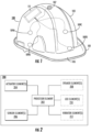
- the example apparatus 100 may comprise a protective headgear 101, an actuator element 107, a plurality of sensor elements (including sensor elements 109A, 109B, 109C, and 109D), and a processor element 111.
- the protective headgear 101 may comprise a shell portion 103 and a brim portion 105.
- the shell portion 103 of the protective headgear 101 may be in a shape similar to a hollow hemisphere or a hollow hemi-ellipsoid such that, when a user wears the protective headgear 101, the shell portion 103 of the protective headgear 101 may provide a covering for the user's head.
- the brim portion 105 may be attached to, molded with, or otherwise connected around the bottom edge of the shell portion 103. In some examples, the brim portion 105 of the protective headgear 101 may protect a user from environmental hazards such as falling debris, rain, or sunlight.
- the protective headgear 101 may comprise material(s) that have durable characteristics so that the protective headgear 101 may, for example, protect the wearer's head from impacts.
- the protective headgear 101 may be at least partially made of metal material, such as aluminum.
- the protective headgear 101 may be at least partially made of plastic material, such as polyethylene (e.g. high-density polyethylene) and/or polycarbonate resin.
- the protective headgear 101 (including the shell portion 103 and/or the brim portion 105) may comprise other suitable materials (such as, for example, fiberglass) without deviating from the scope of the present disclosure.
- the protective headgear 101 may comprise one or more additional components.
- the protective headgear 101 may comprise one or more linings disposed on an inner surface of the protective headgear 101.
- Such linings may incorporate, for example, a headband and suspension bands, which may provide shock absorption during an impact and ventilation during normal wear.
- the user's head may be in contact with the headband and the suspension bands.
- the headband and the suspension bands may suspend the shell portion 103 away from the user's head (for example, 2 centimeters to 3 centimeters above the user's head).
- the protective headgear 101 may comprise a sweatband disposed on an inner surface of the protective headgear 101.
- the sweatband may comprise fabric material (such as cotton) that may absorb sweat from a user's head.
- the protective headgear 101 may comprise a chin strap, and both ends of the chin strap may be connected to the brim portion 105 of the protective headgear 101.
- the protective headgear 101 is in the form of a hard hat, it is noted that the scope of the present disclosure is not limited to hard hat. In some examples, the protective headgear 101 may be in other suitable form(s), such as, for example, safety helmet, bump cap, without deviating from the scope of the present disclosure.
- the apparatus 100 may comprise one or more electronic elements, such as, for example, an actuator element 107 and one or more sensor elements (for example, sensor elements 109A, 109B, 109C, and 109D).
- electronic elements such as, for example, an actuator element 107 and one or more sensor elements (for example, sensor elements 109A, 109B, 109C, and 109D).
- an actuator element in the present disclosure refers to an electronic component or device that may be configured to generate and/or stimulate ultrasonic wave.
- an actuator element may be in the form of, for example but not limited to, an ultrasonic transducer, which may perform the conversion of electrical energy into mechanical energy ( i . e . ultrasonic wave).
- an actuator element of the present disclosure may be in other suitable form(s) without deviating from the scope of the present disclosure.
- a sensor element in the present disclosure refers to an electronic component or device that may be configured to detect and/or measure ultrasonic wave.
- a sensor element may be in the form of, for example but not limited to, an ultrasonic receiver, which may perform the conversion of mechanical energy (i . e . ultrasonic wave) into electrical energy, and/or may generate an output ( e.g. an electric current) based on the detected ultrasonic wave.
- a sensor element of the present disclosure may be in other suitable form(s) without deviating from the scope of the present disclosure.
- the actuator element 107 and the one or more sensor elements may be integrated within the protective headgear 101.
- the term "integrated within” refers to a rigid, structural connection between two structural members that prevents one from rotating or moving with respect to the other.
- the actuator element 107 and/or the sensor elements 109A, 109B, 109C, 109D may be implanted into the protective headgear 101 ( e . g . disposed inside a layer of the shell portion 103).
- the actuator element 107 and/or the sensor elements 109A, 109B, 109C, 109D may be rigidly bonded or attached on an inner surface of the protective headgear 101 through, for example, an adhesive.
- the actuator element 107 may be configured to generate and/or stimulate ultrasonic waves. Because the actuator element 107 is integrated within the protective headgear 101, the ultrasonic waves generated and/or stimulated by the actuator element 107 may be propagated in the protective headgear 101 (including, for example, the shell portion 103 and the brim portion 105). Further, because the sensor elements 109A, 109B, 109C, and 109D are integrated within the protective headgear 101, these sensor elements (109A, 109B, 109C, and 109D) may detect and/or measure ultrasonic waves that have been propagated at various locations of the protective headgear 101.
- the apparatus 100 may also include a processor element 111 that is electronically coupled to the actuator element 107 and the sensor elements 109A, 109B, 109C, and 109D.
- the processor element 111, the actuator element 107, and/or the sensor elements 109A, 109B, 109C, and 109D may be powered by one or more power sources, such as, for example, a battery and/or a power supply unit (PSU).
- PSU power supply unit
- the processor element 111 may be in the form of, for example but not limited to, an application-specific integrated circuit (ASIC) or a central processing unit (CPU). In some examples, the processor element 111 may be in other suitable form(s) without deviating from the scope of the present disclosure.
- ASIC application-specific integrated circuit
- CPU central processing unit
- the processor element 111 may cause the actuator element 107 to generate one or more ultrasonic waves that are propagated in the protective headgear 101, and may receive one or more outputs from the sensor elements 109A, 109B, 109C, and 109D in response to the one or more ultrasonic waves. Based on the one or more outputs, internal defect(s) of the protective headgear 101 may be detected, details of which are described in the present disclosure.
- FIG. 1 shows one actuator element 107
- the scope of the present disclosure is not limited to one actuator element.
- more than one actuator element may be integrated within the protective headgear 101, without deviating from the scope of the present disclosure.
- FIG. 1 shows four sensor elements (sensor elements 109A, 109B, 109C, and 109D), it is noted that the scope of the present disclosure is not limited to four actuator elements. In some examples, less than four or more than four actuator elements may be integrated within the protective headgear 101, without deviating from the scope of the present disclosure.
- FIG. 1 shows that the actuator element 107 is integrated at a top location of the shell portion 103, and that the sensor elements 109A, 109B, 109C, and 109D are integrated at bottom locations of the shell portion 103, it is noted that the scope of the present disclosure is not limited to integrating the actuator element 107 and the sensor elements 109A, 109B, 109C, and 109D at these specific locations. In some examples, an actuator element and/or a sensor element may be integrated at different location(s) than those illustrated in FIG. 1 , without deviating from the scope of the present disclosure.
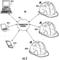
- the example apparatus 200 may comprise a processor element 202 that is electronically coupled to the actuator element(s) 204 and the sensor element(s) 206.
- the processor element 202 may be similar to the processor element 111 described above in connection with FIG. 1 .
- the actuator element(s) 204 may be similar to the actuator element 107 described above in connection with FIG. 1 .
- the sensor element(s) 206 may be similar to the sensor element described above in connection with FIG. 1 (for example, sensor elements 109A, 109B, 109C, and 109D).
- the example apparatus 200 may optionally comprise one or more additional electronic elements, including, for example, speaker element(s) 208, light-emitting diode (LED) element(s) 210, and/or vibrator element(s) 212.
- the processor element 202 may be electronically coupled to the speaker element(s) 208, the light-emitting diode (LED) element(s) 210, and/or the vibrator element(s) 212.
- the speaker element(s) 208 may be disposed on an outer surface of a protective headgear (such as, for example, the protective headgear 101 described above in connection with FIG. 1 ), and may be configured to output audio alerts (for example, an alarm sound and/or a pre-recorded audio message).
- a protective headgear such as, for example, the protective headgear 101 described above in connection with FIG. 1
- the speaker element(s) 208 may be in the form of a printed circuit board (PCB) micro speaker.
- PCB printed circuit board
- the speaker element(s) 208 may be in other suitable form(s), without deviating from the scope of the present disclosure.
- the light-emitting diode (LED) element(s) 210 may be disposed on an outer surface of a protective headgear (such as, for example, the protective headgear 101 described above in connection with FIG. 1 ), and may be configured to output a visual alert (for example, a flashing light and/or a red light).
- a protective headgear such as, for example, the protective headgear 101 described above in connection with FIG. 1
- a visual alert for example, a flashing light and/or a red light
- the vibrator element(s) 212 may be integrated within a protective headgear (such as, for example, the protective headgear 101 described above in connection with FIG. 1 ), and may be configured to output a vibration.
- a protective headgear such as, for example, the protective headgear 101 described above in connection with FIG. 1 .
- the example system 300 may comprise one or more example computing devices (such as, for example, example computing devices 301A, 301B, . . ., 301N) in electronic communication with one or more example apparatuses (such as, for example, apparatuses 305A, 305B, ..., 305N) via one or more communication networks (such as, for example, a communication network 303).
- example computing devices such as, for example, example computing devices 301A, 301B, . . ., 301N
- example apparatuses such as, for example, apparatuses 305A, 305B, ..., 305N
- communication networks such as, for example, a communication network 303.
- the communication network 303 may include one or more wired or wireless communication networks including, for example, a wired or wireless local area network (LAN), personal area network (PAN), metropolitan area network (MAN), wide area network (WAN), or the like, as well as any hardware, software and/or firmware required to implement the one or more networks (such as, for example, network routers).
- LAN local area network
- PAN personal area network
- MAN metropolitan area network
- WAN wide area network
- any hardware, software and/or firmware required to implement the one or more networks such as, for example, network routers.
- communication network 303 may include general packet radio service (GPRS) network, Code Division Multiple Access 2000 (CDMA2000) network, Wideband Code Division Multiple Access (WCDMA) network, Global System for Mobile Communications (GSM) network, Enhanced Data rates for GSM Evolution (EDGE) network, Time Division-Synchronous Code Division Multiple Access (TD-SCDMA) network, Long Term Evolution (LTE) network, High Speed Packet Access (HSPA) network, High-Speed Downlink Packet Access (HSDPA) network, IEEE 802.11 (Wi-Fi), Wi-Fi Direct, and/or IEEE 802.16 (WiMAX).
- GPRS general packet radio service
- CDMA2000 Code Division Multiple Access 2000
- WCDMA Wideband Code Division Multiple Access
- GSM Global System for Mobile Communications
- EDGE Enhanced Data rates for GSM Evolution
- TD-SCDMA Time Division-Synchronous Code Division Multiple Access
- LTE Long Term Evolution
- HSPA High Speed Packet Access
- HSDPA High-Speed Downlink Pack
- the communication network 303 may include a public network (such as the Internet), a private network (such as an intranet), or combinations thereof, and may utilize a variety of networking protocols including, but not limited to, TCP/IP based networking protocols, near field communication (NFC) protocols, Bluetooth protocols, and/or ZigBee protocols.
- a public network such as the Internet
- a private network such as an intranet
- networking protocols including, but not limited to, TCP/IP based networking protocols, near field communication (NFC) protocols, Bluetooth protocols, and/or ZigBee protocols.
- the one or more example computing devices 301A, 301B, ..., 301N may communicate among each other, and may communicate with the one or more example apparatuses 305A, 305B, ..., 305N.
- the one or more example computing devices 301A, 301B, ..., 301N may include servers, desktop computers, laptop computers, smartphones, netbooks, tablet computers, wearables, and the like.
- the one or more example computing devices 301A, 301B, ..., 301N may include one or more processors, such as, for example, single core processor(s) and/or multi-core processor(s).
- the one or more processors may be electronically coupled to one or more memory circuitries, such as, for example, volatile memories and/or non-volatile memories.
- the one or more example computing devices 301A, 301B, ..., 301N may include one or more input/output circuitries (for example, display, touch screen, keyboard, mouse, speaker, and/or microphone coupled to one or more processors).
- one or more input/output circuitries may be configured to provide an application, browser, user interface, dashboard, and/or webpage executing on and/or accessible via an example computing device to cause display of information/data and for user interaction therewith via one or more user interfaces.
- Example user interfaces are illustrated and described at least in connection with FIGS. 5 and 6 .
- the one or more example apparatuses 305A, 305B, ..., 305N may be similar to the example apparatus 100 described above in connection with FIG. 1 . Further, the one or more example apparatuses 305A, 305B, ..., 305N may comprise one or more communications circuitries.
- the communications circuitries may be, for example, a device or circuitry embodied in either hardware or a combination of hardware and software that is configured to receive and/or transmit data from/to the communication network 303.
- Such data may include, for example, output(s) from the processor element(s) and/or sensor element(s) of the one or more example apparatuses 305A, 305B, ..., 305N.
- each block of the flowchart, and combinations of blocks in the flowchart may be implemented by various means such as hardware, firmware, circuitry and/or other devices associated with execution of software including one or more computer program instructions.
- one or more of the procedures described in figures may be embodied by computer program instructions, which may be stored by a memory circuitry (such as a non-transitory memory) of an apparatus employing an embodiment of the present disclosure and executed by a processing circuitry (such as a processor) of the apparatus.
- These computer program instructions may direct the apparatus to function in a particular manner, such that the instructions stored in the memory circuitry produce an article of manufacture, the execution of which implements the function specified in the flowchart block(s).
- the apparatus may comprise one or more other components, such as, for example, actuator element(s) and sensor element(s) described above in connection with FIG. 1 .
- Various components of the apparatus may be in electronic communication between and/or among each other to transmit data to and/or receive data from each other.
- embodiments may take the form of a computer program product on a non-transitory computer-readable storage medium storing computer-readable program instructions (e . g . computer software). Any suitable computer-readable storage medium may be utilized including non-transitory hard disks, CD-ROMs, flash memory, optical storage devices, or magnetic storage devices.
- the example method 400 illustrates example embodiments of calculating various parameters for detecting an internal defect of a protective headgear.
- the method 400 may be performed by a processing circuitry (for example, the processor element 111 described above in connection with FIG. 1 and/or processors of the one or more example computing devices 301A, 301B, .. ., 301N described above in connection with FIG. 3 ).
- the method 400 starts at block 402.
- a processing circuitry may cause an actuator element of an example apparatus (for example, the actuator element 107 of the example apparatus 100 described above in connection with FIG. 1 ) to generate a first ultrasonic wave.
- the actuator element may be integrated within the protective headgear, and the first ultrasonic wave may be propagated in the protective headgear.
- the actuator element may be configured to generate an ultrasonic wave at a fixed frequency. In some examples, the actuator element may be configured to generate ultrasonic waves at different frequencies, without deviating from the scope of the present disclosure.
- a processing circuitry may receive a first output from a sensor element of the example apparatus (for example, the sensor elements 109A, 109B, 109C, or 109D of the example apparatus 100 described above in connection with FIG. 1 ) in response to the first ultrasonic wave.
- a sensor element of the example apparatus for example, the sensor elements 109A, 109B, 109C, or 109D of the example apparatus 100 described above in connection with FIG. 1
- the sensor element may be integrated within the protective headgear, and the ultrasonic wave detected by the sensor element may have been propagated in the protective headgear.
- the output generated by the sensor element at block 406 may correspond to a wavelength of the ultrasonic wave as detected by the sensor element.
- the sensor element may generate one or more output(s) correspond to other properties of the detected ultrasonic wave (for example, amplitude), without deviating from the scope of the present disclosure.
- a processing circuitry may cause the actuator element (for example, the actuator element 107 of the example apparatus 100 described above in connection with FIG. 1 ) to generate a second ultrasonic wave.
- the second ultrasonic wave is propagated in the protective headgear.
- the second ultrasonic wave may have one or more same properties as the first ultrasonic wave generated by the actuator element as described above in connection with block 404.
- the second ultrasonic wave may have the same frequency as the first ultrasonic wave.
- a processing circuitry may receive a second output from the sensor element (for example, the sensor elements 109A, 109B, 109C, or 109D of the example apparatus 100 described above in connection with FIG. 1 ) in response to the second ultrasonic wave.
- the sensor element for example, the sensor elements 109A, 109B, 109C, or 109D of the example apparatus 100 described above in connection with FIG. 1
- the output generated by the sensor element at block 410 may correspond to the same property of the detected ultrasonic wave as the output generated by the sensor element at block 406. For example, when the output generated by the sensor element at block 406 indicates a wavelength detected by the sensor element in response to the first ultrasonic wave, the output generated by the sensor element at block 410 may indicate a wavelength detected by the sensor element in response to the second ultrasonic wave.
- a processing circuitry may determine whether the protective headgear comprises an internal defect. For example, at block 412, the processing circuitry may calculate an output difference between the second output and the first output.
- the output generated by the sensor element at block 406 may indicate a wavelength detected by the sensor element in response to the first ultrasonic wave
- the output generated by the sensor element at block 410 may indicate a wavelength detected by the sensor element in response to the second ultrasonic wave.
- the output difference between the second output and the first output may correspond to a wavelength difference.
- the output difference may correspond to other properties of the detected ultrasonic wave (for example, amplitude), without deviating from the scope of the present disclosure.
- a processing circuitry may determine whether the output difference satisfies a pre-determined threshold.
- the one or more internal defects may create one or more discontinuities in the wave path as the ultrasonic wave being propagated in the protective headgear.
- the one or more discontinuities may reflect back at least part of the ultrasonic wave, creating one or more irregularities in the output generated by the sensor element.
- blocks 404 and 406 may be performed prior to the initial wearing of a protective headgear.
- the first output received by the processor element at block 406 may indicate one or more properties of an ultrasonic wave propagated in a protective headgear that does not comprise any internal defect.
- Blocks 408 and 410 may be performed after the protective headgear has been used. As such, the output difference between the second output and the first output may indicate whether there is any internal defect in the protective headgear.
- blocks 404 and 406 may be performed after the initial wearing of a protective headgear, without deviating from the scope of the present disclosure.
- an example method may compare the first output (or the second output) with a pre-determined value to calculate an output difference, and the pre-determined value may indicate one or more properties of an ultrasonic wave propagated in a protective headgear that does not comprise any internal defect.
- the output difference between the second output and the first output may correspond to a wavelength difference.
- the pre-determined threshold may be set based on the wavelength of the first ultrasonic wave (for example, less than half of the wavelength of the first ultrasonic wave) to reduce the likelihood of erroneous detection and false alarm due to, for example, environmental noise.
- the pre-determined threshold may be set based at least in part on other suitable parameters (for example, the sensitivity and/or resolution of the sensor element), without deviating from the scope of the present disclosure.
- the processing circuitry may determine that there is no internal defect in the protective headgear, and the method 400 ends at block 416.
- the method 400 proceed to block 414.
- the processing circuitry may trigger a warning in response to determining that the output difference does not satisfy the pre-determined threshold.
- the processing circuitry may cause an example speaker element to output an audio alert.
- an example speaker element may be disposed on an outer surface of the protective headgear. Additionally or alternatively, an example speaker element may be separated from the protective headgear.
- the processing circuitry may cause an example light-emitting diode (LED) element to output an audio alert.
- LED light-emitting diode
- an example LED element may be disposed on an outer surface of the protective headgear. Additionally or alternatively, an example LED element may be separated from the protective headgear.
- the processing circuitry may cause an example vibrator element to output a vibration.
- an example vibrator element may be integrated within the protective headgear. Additionally or alternatively, an example vibrator element may be separated from the protective headgear.
- the method 400 ends at block 416.
- example user interfaces in accordance with various examples of the present disclosure are illustrated.
- a user may operate an example computing device (such as, for example, example computing devices 301A, 301B, ..., 301N described above in connection with FIG. 3 ) to view and/or interact with example user interfaces as illustrated in FIGS. 5-6 via a display of the example computing device.
- an example computing device such as, for example, example computing devices 301A, 301B, ..., 301N described above in connection with FIG. 3
- example computing device such as, for example computing devices 301A, 301B, ..., 301N described above in connection with FIG. 3
- example computing device such as, for example computing devices 301A, 301B, ..., 301N described above in connection with FIG. 3
- the scope of the present disclosure is not limited to desktop computer or mobile phone, and other devices may be used in accordance with embodiments of the present disclosure (including, for example, wearable devices) to view and/or interact with example user interfaces in accordance
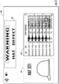
- an example user interface 500 is shown.
- the example user interface 500 illustrates an example dashboard interface for monitoring a single protective headgear.
- the user interface 500 may comprise a protective headgear identification portion 501 and an output rendering portion 503.
- the protective headgear identification portion 501 may display a graphic representation of the protective headgear, and/or an identification number of the protective headgear.
- the output rendering portion 503 may comprise rendering of output(s) associated with sensor element(s) and/or the processor element integrated within the protective headgear.
- the processor element may (process and) transmit the first output and the second output to the computing device, and may cause the rendering of the first output and the second output on the output rendering portion 503 of the user interface 500.
- the output rendering portion 503 may also display date and time associated with each output.
- the user interface 500 may further comprise a warning portion 505, which may display a warning message that there may be internal defect(s) in the protective headgear.
- a plurality of example apparatuses in accordance with the present disclosure may be in electronic communication with one or more computing device.
- one computing device may be configured to receive data from a group of example apparatuses.
- FIG. 6 an example user interface 600 is shown.
- the example user interface 600 illustrates an example dashboard interface for monitoring a group of protective headgears.
- the user interface 600 may comprise a headgear identification portion 602 and an output rendering portion 604.
- the headgear identification portion 602 may display graphic representations of protective headgears within the group.
- each of the protective headgears may be associated with a unique identifier, and unique identifiers of protective headgears in the group may be stored in a memory circuitry of the computing device.
- the unique identifier may be in the form of a number string, an American Standard Code for Information Interchange (ASCII) text, a pointer, and/or the like.
- ASCII American Standard Code for Information Interchange
- the headgear identification portion 602 may indicate the status of each protective headgear in the group.
- a shaded graphic representation of a protective headgear may indicate that the corresponding protective headgear may comprise one or more defects.
- a color-filled graphic representation of a protective headgear may indicate that the corresponding protective headgear may soon be affected by one or more internal defects, as described below.
- the output rendering portion 604 may comprise rendering of one or more output(s) associated with sensor element(s) and/or the processor element integrated within the protective headgears in the group, similar to the output rendering portion 503 described above in connection with FIG. 5 .
- each of the outputs may be associated with a unique identifier.
- the outputs may be rendered as bars in the bar graph in the output rendering portion 604.
- the user interface 600 may also comprise a group status portion 606.
- the group status portion 606 may display information such as, for example, the unique identifiers of protective headgears that may comprise one or more internal defects (for example, based on the method 400 described above in connection with FIG. 4 ). Additionally or alternatively, the group status portion 606 may display information indicating the "health status" of protective headgear group, which may be calculated based on dividing the number of protective headgears that do not comprise internal defect by the total number of protective headgears in the group.
- the computing device may implement machine learning models (such as, for example, time-series forecasting models) based on historical data associated with the protective headgears in the group to generate a forecast of protective headgear(s) that may soon be affected by one or more internal defects.
- the group status portion 606 may display information indicating the unique identifier(s) of protective headgear(s) that may soon be affected by one or more internal defects.
- the user interface 600 may display these unique identifiers after the "Replacement Forecast" button 608 is clicked, tapped, or otherwise selected by a user operating the computing device.
- the user interface 600 may comprise one or more buttons, such as the "Stock” button 610, the "Order” button 612, and the "More Information” button 614.
- the user interface 600 may display the total number of protective headgears in the group.
- the computing device may render one or more user interfaces that may facilitate the ordering of an example apparatus in accordance with the present disclosure.
- the user interface 600 may display additional information associated with the protective headgear group.
Landscapes
- Physics & Mathematics (AREA)
- Biochemistry (AREA)
- General Physics & Mathematics (AREA)
- Life Sciences & Earth Sciences (AREA)
- Chemical & Material Sciences (AREA)
- Analytical Chemistry (AREA)
- Pathology (AREA)
- General Health & Medical Sciences (AREA)
- Health & Medical Sciences (AREA)
- Immunology (AREA)
- Acoustics & Sound (AREA)
- Engineering & Computer Science (AREA)
- Signal Processing (AREA)
- Helmets And Other Head Coverings (AREA)
- User Interface Of Digital Computer (AREA)
Abstract
Description
- The present disclosure relates generally to methods, apparatuses, and systems associated with a protective headgear, and more particularly, to methods, apparatuses, and systems for providing a protective headgear comprising integrated actuator element(s) and sensor element(s) for detecting internal defect in the protective headgear.
- In workplace environments (such as, but not limited to, construction sites, demolition sites, warehouse sites), workers may be exposed to head injurie risks due to, for example, accidentally dropped objects that may strike worker's head, worker accidentally bumping his head against fixtures (such as exposed beams), and electric shock resulting from accidental head contact. In many situations, protecting workers from head injury risks may be an important element in a workplace safety program.
- Protective headgear is a type of personal protective equipment (PPE) that may reduce head injury risks while a user is wearing the protective headgear. Example forms of protective headgear may include, but not limited to, safety helmet, bump hat, and hard hat. For example, hard hats may protect workers from impact forces and penetration hazards to the head, and may also reduce the risk of being exposed to electric shock. Further, wearing a hard hat may make the worker more visible to others in the workplace environment.
- However, existing systems and methods do not overcome many technical challenges and difficulties associated with protective headgear. For example, existing systems and methods fail to provide an effective and efficient way to detect internal defect(s) of protective headgear. Example internal defects may include, but not limited to, perforation, deformity, cracking, tearing, aging, and injection defects in or on the protective headgear. In some examples, internal defect(s) may not be visible when the protective headgear is inspected with a naked eye. A worker may unknowingly wear a protective headgear provided by the existing systems and methods that comprise internal defect(s), which may pose safety risks to the worker.
- Various embodiments described herein relate to methods, apparatuses, and systems for providing a protective headgear. In particular, various embodiments are related to detecting internal defect(s) of protective headgear based on, for example, actuator element(s) and sensor element(s) that are integrated within the protective headgear.
- In accordance with various embodiments of the present disclosure, an example apparatus is provided. The example apparatus may comprise a protective headgear, an actuator element integrated within the protective headgear, a sensor element integrated within the protective headgear, and a processor element electronically coupled to the actuator element and the sensor element. In some examples, the processor element may be configured to: cause the actuator element to generate a first ultrasonic wave, and receive a first output from the sensor element in response to the first ultrasonic wave. In some examples, the first ultrasonic wave may be propagated in the protective headgear.
- In some examples, the processor element may be further configured to cause the actuator element to generate a second ultrasonic wave, receive a second output from the sensor element in response to the second ultrasonic wave, and determine whether the protective headgear comprises an internal defect based on the first output and the second output. In some examples, the second ultrasonic wave is propagated in the protective headgear.
- In some examples, when determining whether the protective headgear comprises the internal defect, the processor element may be further configured to calculate an output difference between the second output and the first output, and determine whether the output difference satisfies a pre-determined threshold.
- In some examples, the example apparatus may further comprise a speaker element that is disposed on an outer surface of the protective headgear and electronically coupled to the processor element. In some examples, the processor element may be further configured to: determine that the output difference does not satisfy the pre-determined threshold, and in response to determining that the output difference does not satisfy the pre-determined threshold, cause the speaker element to output an audio alert.
- In some examples, the example apparatus may further comprise a light-emitting diode (LED) element that is disposed on an outer surface of the protective headgear and electronically coupled to the processor element. In some examples, the processor element may be further configured to: determine that the output difference does not satisfy the pre-determined threshold, and in response to determining that the output difference does not satisfy the pre-determined threshold, cause the LED element to generate a visual alert.
- In some examples, the example apparatus may further comprise a vibrator element that is integrated within the protective headgear and electronically coupled to the processor element. In some examples, the processor element may be further configured to: determine that the output difference does not satisfy the pre-determined threshold, and in response to determining that the output difference does not satisfy the pre-determined threshold, cause the vibrator element to generate a vibration.
- In some examples, the processor element may be further configured to transmit the first output and the second output to a computing device, and cause a rendering of the first output and the second output on a display of the computing device.
- In accordance with various embodiments of the present disclosure, an example method for detecting an internal defect of a protective headgear is provided. The example method may comprise causing an actuator element to generate a first ultrasonic wave, and receiving a first output from a sensor element in response to the first ultrasonic wave. In some examples, the actuator element is integrated within the protective headgear. In some examples, the sensor element is integrated within the protective headgear. In some examples, the first ultrasonic wave is propagated in the protective headgear.
- In some examples, the example method may further comprise causing the actuator element to generate a second ultrasonic wave, receiving a second output from the sensor element in response to the second ultrasonic wave, and determining whether the protective headgear comprises the internal defect based on the first output and the second output. In some examples, the second ultrasonic wave is propagated in the protective headgear.
- In accordance with various embodiments of the present disclosure, an example computer program product is provided. The example computer program product comprises at least one non-transitory computer-readable storage medium having computer-readable program code portions stored therein, the computer-readable program code portions comprising an executable portion configured to: cause an actuator element to generate a first ultrasonic wave, and receive a first output from a sensor element in response to the first ultrasonic wave. In some examples, the actuator element is integrated within a protective headgear, and the sensor element is integrated within the protective headgear. In some examples, the first ultrasonic wave is propagated in the protective headgear.
- In accordance with various embodiments of the present disclosure, an example system is provided. The example system may comprise a plurality of protective headgears in electronic communication with a computing device. Each of the protective headgears may comprise an actuator element, a sensor element, and a processor element that are integrated within the protective headgear. The computing device may provide a user interface that facilitates status management of the protective headgears.
- The foregoing illustrative summary, as well as other exemplary objectives and/or advantages of the disclosure, and the manner in which the same are accomplished, are further explained in the following detailed description and its accompanying drawings.
- The description of the illustrative embodiments may be read in conjunction with the accompanying figures. It will be appreciated that, for simplicity and clarity of illustration, elements illustrated in the figures have not necessarily been drawn to scale, unless described otherwise. For example, the dimensions of some of the elements may be exaggerated relative to other elements, unless described otherwise. Embodiments incorporating teachings of the present disclosure are shown and described with respect to the figures presented herein, in which:
-
FIG. 1 illustrates an example schematic diagram of an example apparatus in accordance with various embodiments of the present disclosure; -
FIG. 2 illustrates an example block diagram of an example apparatus in accordance with various embodiments of the present disclosure; -
FIG. 3 illustrates an example schematic diagram of an example system in accordance with various embodiments of the present disclosure; -
FIG. 4 illustrates an example flow diagram in accordance with various embodiments of the present disclosure; -
FIG. 5 illustrates an example user interface in accordance with various embodiments of the present disclosure; and -
FIG. 6 illustrates an example user interface in accordance with various embodiments of the present disclosure. - Some embodiments of the present disclosure will now be described more fully hereinafter with reference to the accompanying drawings, in which some, but not all embodiments of the disclosure are shown. Indeed, these disclosures may be embodied in many different forms and should not be construed as limited to the embodiments set forth herein; rather, these embodiments are provided so that this disclosure will satisfy applicable legal requirements. Like numbers refer to like elements throughout.
- The phrases "in one embodiment," "according to one embodiment," and the like generally mean that the particular feature, structure, or characteristic following the phrase may be included in at least one embodiment of the present disclosure, and may be included in more than one embodiment of the present disclosure (importantly, such phrases do not necessarily refer to the same embodiment).
- The word "example" or "exemplary" is used herein to mean "serving as an example, instance, or illustration." Any implementation described herein as "exemplary" is not necessarily to be construed as preferred or advantageous over other implementations.
- If the specification states a component or feature "may," "can," "could," "should," "would," "preferably," "possibly," "typically," "optionally," "for example," "often," or "might" (or other such language) be included or have a characteristic, that specific component or feature is not required to be included or to have the characteristic. Such component or feature may be optionally included in some embodiments, or it may be excluded.
- The term "electronically coupled" in the present disclosure refers to two or more components (for example but not limited to, actuator element(s), sensor element(s), processor element(s), speaker element(s), light-emitting diode (LED) element(s), vibrator element(s)) and/or electric circuit(s) being connected through wired means (for example but not limited to, conductive wires or traces) and/or wireless means (for example but not limited to, electromagnetic field), such that data and/or information may be transmitted to and/or received from the components that are electronically coupled.
- As described above, existing systems and methods do not overcome many technical challenges and difficulties associated with protective headgear. In accordance with various embodiments of the present disclosure, example methods, systems, and apparatuses may provide an effective way to detect internal defect(s) of a protective headgear by, for example, integrating an actuator element, a sensor element, and a processor element within the protective headgear.
- Referring now to
FIG. 1 , anexample apparatus 100 in accordance with various embodiments of the present disclosure is shown. In the example embodiment as shown inFIG. 1 , theexample apparatus 100 may comprise aprotective headgear 101, anactuator element 107, a plurality of sensor elements (includingsensor elements processor element 111. Theprotective headgear 101 may comprise ashell portion 103 and abrim portion 105. - In some examples, the
shell portion 103 of theprotective headgear 101 may be in a shape similar to a hollow hemisphere or a hollow hemi-ellipsoid such that, when a user wears theprotective headgear 101, theshell portion 103 of theprotective headgear 101 may provide a covering for the user's head. - In some examples, the
brim portion 105 may be attached to, molded with, or otherwise connected around the bottom edge of theshell portion 103. In some examples, thebrim portion 105 of theprotective headgear 101 may protect a user from environmental hazards such as falling debris, rain, or sunlight. - In some examples, the protective headgear 101 (including the
shell portion 103 and/or the brim portion 105) may comprise material(s) that have durable characteristics so that theprotective headgear 101 may, for example, protect the wearer's head from impacts. In some examples, the protective headgear 101 (including theshell portion 103 and/or the brim portion 105) may be at least partially made of metal material, such as aluminum. In some examples, the protective headgear 101 (including theshell portion 103 and/or the brim portion 105) may be at least partially made of plastic material, such as polyethylene (e.g. high-density polyethylene) and/or polycarbonate resin. In some examples, the protective headgear 101 (including theshell portion 103 and/or the brim portion 105) may comprise other suitable materials (such as, for example, fiberglass) without deviating from the scope of the present disclosure. - In some examples, the
protective headgear 101 may comprise one or more additional components. For example, theprotective headgear 101 may comprise one or more linings disposed on an inner surface of theprotective headgear 101. Such linings may incorporate, for example, a headband and suspension bands, which may provide shock absorption during an impact and ventilation during normal wear. For example, when a user wears theprotective headgear 101, the user's head may be in contact with the headband and the suspension bands. The headband and the suspension bands may suspend theshell portion 103 away from the user's head (for example, 2 centimeters to 3 centimeters above the user's head). - As another example, the
protective headgear 101 may comprise a sweatband disposed on an inner surface of theprotective headgear 101. The sweatband may comprise fabric material (such as cotton) that may absorb sweat from a user's head. As another example, theprotective headgear 101 may comprise a chin strap, and both ends of the chin strap may be connected to thebrim portion 105 of theprotective headgear 101. - While the example embodiment as illustrated in
FIG. 1 shows that theprotective headgear 101 is in the form of a hard hat, it is noted that the scope of the present disclosure is not limited to hard hat. In some examples, theprotective headgear 101 may be in other suitable form(s), such as, for example, safety helmet, bump cap, without deviating from the scope of the present disclosure. - Referring back to
FIG. 1 , theapparatus 100 may comprise one or more electronic elements, such as, for example, anactuator element 107 and one or more sensor elements (for example,sensor elements - The term "actuator element" in the present disclosure refers to an electronic component or device that may be configured to generate and/or stimulate ultrasonic wave. In some examples, an actuator element may be in the form of, for example but not limited to, an ultrasonic transducer, which may perform the conversion of electrical energy into mechanical energy (i.e. ultrasonic wave). In some examples, an actuator element of the present disclosure may be in other suitable form(s) without deviating from the scope of the present disclosure.
- The term "sensor element" in the present disclosure refers to an electronic component or device that may be configured to detect and/or measure ultrasonic wave. In some examples, a sensor element may be in the form of, for example but not limited to, an ultrasonic receiver, which may perform the conversion of mechanical energy (i.e. ultrasonic wave) into electrical energy, and/or may generate an output (e.g. an electric current) based on the detected ultrasonic wave. In some examples, a sensor element of the present disclosure may be in other suitable form(s) without deviating from the scope of the present disclosure.
- In some examples, the
actuator element 107 and the one or more sensor elements (for example,sensor elements protective headgear 101. The term "integrated within" refers to a rigid, structural connection between two structural members that prevents one from rotating or moving with respect to the other. For example, theactuator element 107 and/or thesensor elements actuator element 107 and/or thesensor elements protective headgear 101 through, for example, an adhesive. - As described above, the
actuator element 107 may be configured to generate and/or stimulate ultrasonic waves. Because theactuator element 107 is integrated within theprotective headgear 101, the ultrasonic waves generated and/or stimulated by theactuator element 107 may be propagated in the protective headgear 101 (including, for example, theshell portion 103 and the brim portion 105). Further, because thesensor elements protective headgear 101, these sensor elements (109A, 109B, 109C, and 109D) may detect and/or measure ultrasonic waves that have been propagated at various locations of theprotective headgear 101. - Referring back to
FIG. 1 , theapparatus 100 may also include aprocessor element 111 that is electronically coupled to theactuator element 107 and thesensor elements processor element 111, theactuator element 107, and/or thesensor elements - In some examples, the
processor element 111 may be in the form of, for example but not limited to, an application-specific integrated circuit (ASIC) or a central processing unit (CPU). In some examples, theprocessor element 111 may be in other suitable form(s) without deviating from the scope of the present disclosure. - In some examples, the
processor element 111 may cause theactuator element 107 to generate one or more ultrasonic waves that are propagated in theprotective headgear 101, and may receive one or more outputs from thesensor elements protective headgear 101 may be detected, details of which are described in the present disclosure. - While the example embodiment as illustrated in
FIG. 1 shows oneactuator element 107, it is noted that the scope of the present disclosure is not limited to one actuator element. In some examples, more than one actuator element may be integrated within theprotective headgear 101, without deviating from the scope of the present disclosure. - While the example embodiment as illustrated in
FIG. 1 shows four sensor elements (sensor elements protective headgear 101, without deviating from the scope of the present disclosure. - While the example embodiment as illustrated in
FIG. 1 shows that theactuator element 107 is integrated at a top location of theshell portion 103, and that thesensor elements shell portion 103, it is noted that the scope of the present disclosure is not limited to integrating theactuator element 107 and thesensor elements FIG. 1 , without deviating from the scope of the present disclosure. - Referring now to
FIG. 2 , an example block diagram illustrate various electronic elements of anexample apparatus 200 in accordance of the present disclosure is shown. For example, theexample apparatus 200 may comprise aprocessor element 202 that is electronically coupled to the actuator element(s) 204 and the sensor element(s) 206. - In some examples, the
processor element 202 may be similar to theprocessor element 111 described above in connection withFIG. 1 . In some examples, the actuator element(s) 204 may be similar to theactuator element 107 described above in connection withFIG. 1 . In some examples, the sensor element(s) 206 may be similar to the sensor element described above in connection withFIG. 1 (for example,sensor elements - Further, as shown in
FIG. 2 , theexample apparatus 200 may optionally comprise one or more additional electronic elements, including, for example, speaker element(s) 208, light-emitting diode (LED) element(s) 210, and/or vibrator element(s) 212. In some examples, theprocessor element 202 may be electronically coupled to the speaker element(s) 208, the light-emitting diode (LED) element(s) 210, and/or the vibrator element(s) 212. - In some examples, the speaker element(s) 208 may be disposed on an outer surface of a protective headgear (such as, for example, the
protective headgear 101 described above in connection withFIG. 1 ), and may be configured to output audio alerts (for example, an alarm sound and/or a pre-recorded audio message). In some examples, the speaker element(s) 208 may be in the form of a printed circuit board (PCB) micro speaker. In some examples, the speaker element(s) 208 may be in other suitable form(s), without deviating from the scope of the present disclosure. - In some examples, the light-emitting diode (LED) element(s) 210 may be disposed on an outer surface of a protective headgear (such as, for example, the
protective headgear 101 described above in connection withFIG. 1 ), and may be configured to output a visual alert (for example, a flashing light and/or a red light). - In some examples, the vibrator element(s) 212 may be integrated within a protective headgear (such as, for example, the
protective headgear 101 described above in connection withFIG. 1 ), and may be configured to output a vibration. - Referring now to
FIG. 3 , anexample system 300 in accordance with various embodiments of the present disclosure is shown. In some examples, theexample system 300 may comprise one or more example computing devices (such as, for example,example computing devices apparatuses - The
communication network 303 may include one or more wired or wireless communication networks including, for example, a wired or wireless local area network (LAN), personal area network (PAN), metropolitan area network (MAN), wide area network (WAN), or the like, as well as any hardware, software and/or firmware required to implement the one or more networks (such as, for example, network routers). For example,communication network 303 may include general packet radio service (GPRS) network, Code Division Multiple Access 2000 (CDMA2000) network, Wideband Code Division Multiple Access (WCDMA) network, Global System for Mobile Communications (GSM) network, Enhanced Data rates for GSM Evolution (EDGE) network, Time Division-Synchronous Code Division Multiple Access (TD-SCDMA) network, Long Term Evolution (LTE) network, High Speed Packet Access (HSPA) network, High-Speed Downlink Packet Access (HSDPA) network, IEEE 802.11 (Wi-Fi), Wi-Fi Direct, and/or IEEE 802.16 (WiMAX). Additionally or alternatively, thecommunication network 303 may include a public network (such as the Internet), a private network (such as an intranet), or combinations thereof, and may utilize a variety of networking protocols including, but not limited to, TCP/IP based networking protocols, near field communication (NFC) protocols, Bluetooth protocols, and/or ZigBee protocols. - Via the
communication network 303, the one or moreexample computing devices more example apparatuses example computing devices - In some examples, the one or more
example computing devices - In some examples, the one or more
example computing devices FIGS. 5 and6 . - Referring back to
FIG. 3 , the one ormore example apparatuses example apparatus 100 described above in connection withFIG. 1 . Further, the one ormore example apparatuses communication network 303. Such data may include, for example, output(s) from the processor element(s) and/or sensor element(s) of the one ormore example apparatuses - Referring now to
FIG. 4 , example methods in accordance with various embodiments of the present disclosure are illustrated. In some examples, each block of the flowchart, and combinations of blocks in the flowchart, may be implemented by various means such as hardware, firmware, circuitry and/or other devices associated with execution of software including one or more computer program instructions. - In some examples, one or more of the procedures described in figures may be embodied by computer program instructions, which may be stored by a memory circuitry (such as a non-transitory memory) of an apparatus employing an embodiment of the present disclosure and executed by a processing circuitry (such as a processor) of the apparatus. These computer program instructions may direct the apparatus to function in a particular manner, such that the instructions stored in the memory circuitry produce an article of manufacture, the execution of which implements the function specified in the flowchart block(s). Further, the apparatus may comprise one or more other components, such as, for example, actuator element(s) and sensor element(s) described above in connection with
FIG. 1 . Various components of the apparatus may be in electronic communication between and/or among each other to transmit data to and/or receive data from each other. - In some examples, embodiments may take the form of a computer program product on a non-transitory computer-readable storage medium storing computer-readable program instructions (e.g. computer software). Any suitable computer-readable storage medium may be utilized including non-transitory hard disks, CD-ROMs, flash memory, optical storage devices, or magnetic storage devices.
- Referring back to
FIG. 4 , anexample method 400 in accordance with some embodiments of the present disclosure is illustrated. In particular, theexample method 400 illustrates example embodiments of calculating various parameters for detecting an internal defect of a protective headgear. In some examples, themethod 400 may be performed by a processing circuitry (for example, theprocessor element 111 described above in connection withFIG. 1 and/or processors of the one or moreexample computing devices FIG. 3 ). - The
method 400 starts atblock 402. - At block 404, a processing circuitry (for example, the
processor element 111 described above in connection withFIG. 1 and/or processors of the one or moreexample computing devices FIG. 3 ) may cause an actuator element of an example apparatus (for example, theactuator element 107 of theexample apparatus 100 described above in connection withFIG. 1 ) to generate a first ultrasonic wave. As described above in connection withFIG. 1 , the actuator element may be integrated within the protective headgear, and the first ultrasonic wave may be propagated in the protective headgear. - In some examples, the actuator element may be configured to generate an ultrasonic wave at a fixed frequency. In some examples, the actuator element may be configured to generate ultrasonic waves at different frequencies, without deviating from the scope of the present disclosure.
- At
block 406, a processing circuitry (for example, theprocessor element 111 described above in connection withFIG. 1 and/or processors of the one or moreexample computing devices FIG. 3 ) may receive a first output from a sensor element of the example apparatus (for example, thesensor elements example apparatus 100 described above in connection withFIG. 1 ) in response to the first ultrasonic wave. As described above in connection withFIG. 1 , the sensor element may be integrated within the protective headgear, and the ultrasonic wave detected by the sensor element may have been propagated in the protective headgear. - In some examples, the output generated by the sensor element at
block 406 may correspond to a wavelength of the ultrasonic wave as detected by the sensor element. In some examples, the sensor element may generate one or more output(s) correspond to other properties of the detected ultrasonic wave (for example, amplitude), without deviating from the scope of the present disclosure. - At block 408, a processing circuitry (for example, the
processor element 111 described above in connection withFIG. 1 and/or processors of the one or moreexample computing devices FIG. 3 ) may cause the actuator element (for example, theactuator element 107 of theexample apparatus 100 described above in connection withFIG. 1 ) to generate a second ultrasonic wave. - In some examples, the second ultrasonic wave is propagated in the protective headgear. In some examples, the second ultrasonic wave may have one or more same properties as the first ultrasonic wave generated by the actuator element as described above in connection with block 404. For example, the second ultrasonic wave may have the same frequency as the first ultrasonic wave.
- At
block 410, a processing circuitry (for example, theprocessor element 111 described above in connection withFIG. 1 and/or processors of the one or moreexample computing devices FIG. 3 ) may receive a second output from the sensor element (for example, thesensor elements example apparatus 100 described above in connection withFIG. 1 ) in response to the second ultrasonic wave. - In some examples, the output generated by the sensor element at
block 410 may correspond to the same property of the detected ultrasonic wave as the output generated by the sensor element atblock 406. For example, when the output generated by the sensor element atblock 406 indicates a wavelength detected by the sensor element in response to the first ultrasonic wave, the output generated by the sensor element atblock 410 may indicate a wavelength detected by the sensor element in response to the second ultrasonic wave. - Based on the first output and the second output, a processing circuitry (for example, the
processor element 111 described above in connection withFIG. 1 and/or processors of the one or moreexample computing devices FIG. 3 ) may determine whether the protective headgear comprises an internal defect. For example, atblock 412, the processing circuitry may calculate an output difference between the second output and the first output. - As described above, in some examples, the output generated by the sensor element at
block 406 may indicate a wavelength detected by the sensor element in response to the first ultrasonic wave, and the output generated by the sensor element atblock 410 may indicate a wavelength detected by the sensor element in response to the second ultrasonic wave. In such examples, the output difference between the second output and the first output may correspond to a wavelength difference. In some examples, the output difference may correspond to other properties of the detected ultrasonic wave (for example, amplitude), without deviating from the scope of the present disclosure. - Referring back to block 412, a processing circuitry (for example, the
processor element 111 described above in connection withFIG. 1 and/or processors of the one or moreexample computing devices FIG. 3 ) may determine whether the output difference satisfies a pre-determined threshold. - In some examples, when one or more internal defects (for example, a crack) exist in a protective headgear, the one or more internal defects may create one or more discontinuities in the wave path as the ultrasonic wave being propagated in the protective headgear. The one or more discontinuities may reflect back at least part of the ultrasonic wave, creating one or more irregularities in the output generated by the sensor element.
- In some examples, blocks 404 and 406 may be performed prior to the initial wearing of a protective headgear. In such examples, the first output received by the processor element at
block 406 may indicate one or more properties of an ultrasonic wave propagated in a protective headgear that does not comprise any internal defect.Blocks 408 and 410 may be performed after the protective headgear has been used. As such, the output difference between the second output and the first output may indicate whether there is any internal defect in the protective headgear. In some examples, blocks 404 and 406 may be performed after the initial wearing of a protective headgear, without deviating from the scope of the present disclosure. - Additionally or alternatively, an example method may compare the first output (or the second output) with a pre-determined value to calculate an output difference, and the pre-determined value may indicate one or more properties of an ultrasonic wave propagated in a protective headgear that does not comprise any internal defect.
- As described above, in some examples, the output difference between the second output and the first output may correspond to a wavelength difference. In such examples, the pre-determined threshold may be set based on the wavelength of the first ultrasonic wave (for example, less than half of the wavelength of the first ultrasonic wave) to reduce the likelihood of erroneous detection and false alarm due to, for example, environmental noise. In some examples, the pre-determined threshold may be set based at least in part on other suitable parameters (for example, the sensitivity and/or resolution of the sensor element), without deviating from the scope of the present disclosure.
- Referring back to
FIG. 4 , in response to determining that the output difference satisfies the pre-determined threshold (for example, the output difference being less than half of the wavelength of the first ultrasonic wave), the processing circuitry may determine that there is no internal defect in the protective headgear, and themethod 400 ends atblock 416. - In response to determining that the output difference does not satisfy the pre-determined threshold (for example, the output difference being equal to or more than half of the wavelength of the first ultrasonic wave), the
method 400 proceed to block 414. Atblock 414, the processing circuitry may trigger a warning in response to determining that the output difference does not satisfy the pre-determined threshold. - For example, the processing circuitry may cause an example speaker element to output an audio alert. As described in connection with
FIG. 2 above, an example speaker element may be disposed on an outer surface of the protective headgear. Additionally or alternatively, an example speaker element may be separated from the protective headgear. - As another example, the processing circuitry may cause an example light-emitting diode (LED) element to output an audio alert. As described in connection with
FIG. 2 above, an example LED element may be disposed on an outer surface of the protective headgear. Additionally or alternatively, an example LED element may be separated from the protective headgear. - As another example, the processing circuitry may cause an example vibrator element to output a vibration. As described in connection with
FIG. 2 above, an example vibrator element may be integrated within the protective headgear. Additionally or alternatively, an example vibrator element may be separated from the protective headgear. - The
method 400 ends atblock 416. - Referring now to
FIGS. 5-6 , example user interfaces in accordance with various examples of the present disclosure are illustrated. In particular, a user may operate an example computing device (such as, for example,example computing devices FIG. 3 ) to view and/or interact with example user interfaces as illustrated inFIGS. 5-6 via a display of the example computing device. It is noted that the scope of the present disclosure is not limited to desktop computer or mobile phone, and other devices may be used in accordance with embodiments of the present disclosure (including, for example, wearable devices) to view and/or interact with example user interfaces in accordance with various embodiments of the present disclosure. - Referring now to
FIG. 5 , anexample user interface 500 is shown. In particular, theexample user interface 500 illustrates an example dashboard interface for monitoring a single protective headgear. As shown inFIG. 5 , theuser interface 500 may comprise a protectiveheadgear identification portion 501 and anoutput rendering portion 503. - The protective
headgear identification portion 501 may display a graphic representation of the protective headgear, and/or an identification number of the protective headgear. Theoutput rendering portion 503 may comprise rendering of output(s) associated with sensor element(s) and/or the processor element integrated within the protective headgear. For example, the processor element may (process and) transmit the first output and the second output to the computing device, and may cause the rendering of the first output and the second output on theoutput rendering portion 503 of theuser interface 500. In the example embodiment as shown inFIG. 5 , theoutput rendering portion 503 may also display date and time associated with each output. - In some examples, when a processing circuitry (for example, the
processor element 111 described above in connection withFIG. 1 and/or processors of the one or moreexample computing devices FIG. 3 ) determine that the protective headgear (as indicated in the protective headgear identification portion 501) comprises one or more internal defects (for example, based on themethod 400 described above in connection withFIG. 4 ), theuser interface 500 may further comprise awarning portion 505, which may display a warning message that there may be internal defect(s) in the protective headgear. - As illustrated above in connection with
FIG. 3 , a plurality of example apparatuses in accordance with the present disclosure may be in electronic communication with one or more computing device. As such, one computing device may be configured to receive data from a group of example apparatuses. Referring now toFIG. 6 , anexample user interface 600 is shown. In particular, theexample user interface 600 illustrates an example dashboard interface for monitoring a group of protective headgears. - As shown in
FIG. 6 , theuser interface 600 may comprise aheadgear identification portion 602 and anoutput rendering portion 604. - The
headgear identification portion 602 may display graphic representations of protective headgears within the group. In some examples, each of the protective headgears may be associated with a unique identifier, and unique identifiers of protective headgears in the group may be stored in a memory circuitry of the computing device. In some examples, the unique identifier may be in the form of a number string, an American Standard Code for Information Interchange (ASCII) text, a pointer, and/or the like. - In some examples, the
headgear identification portion 602 may indicate the status of each protective headgear in the group. For example, a shaded graphic representation of a protective headgear may indicate that the corresponding protective headgear may comprise one or more defects. As another example, a color-filled graphic representation of a protective headgear may indicate that the corresponding protective headgear may soon be affected by one or more internal defects, as described below. - The
output rendering portion 604 may comprise rendering of one or more output(s) associated with sensor element(s) and/or the processor element integrated within the protective headgears in the group, similar to theoutput rendering portion 503 described above in connection withFIG. 5 . In some examples, each of the outputs may be associated with a unique identifier. In the example embodiment as shown inFIG. 6 , the outputs may be rendered as bars in the bar graph in theoutput rendering portion 604. - In some examples, the
user interface 600 may also comprise agroup status portion 606. Thegroup status portion 606 may display information such as, for example, the unique identifiers of protective headgears that may comprise one or more internal defects (for example, based on themethod 400 described above in connection withFIG. 4 ). Additionally or alternatively, thegroup status portion 606 may display information indicating the "health status" of protective headgear group, which may be calculated based on dividing the number of protective headgears that do not comprise internal defect by the total number of protective headgears in the group. - In some examples, the computing device may implement machine learning models (such as, for example, time-series forecasting models) based on historical data associated with the protective headgears in the group to generate a forecast of protective headgear(s) that may soon be affected by one or more internal defects. In some examples, the
group status portion 606 may display information indicating the unique identifier(s) of protective headgear(s) that may soon be affected by one or more internal defects. In some examples, theuser interface 600 may display these unique identifiers after the "Replacement Forecast"button 608 is clicked, tapped, or otherwise selected by a user operating the computing device. - In some examples, the
user interface 600 may comprise one or more buttons, such as the "Stock"button 610, the "Order"button 612, and the "More Information"button 614. When a user clicks, taps, or otherwise selects the "Stock"button 610, theuser interface 600 may display the total number of protective headgears in the group. When a user clicks, taps, or otherwise selects the "Order"button 612, the computing device may render one or more user interfaces that may facilitate the ordering of an example apparatus in accordance with the present disclosure. When a user clicks, taps, or otherwise selects the "More Information"button 614, theuser interface 600 may display additional information associated with the protective headgear group. - It is to be understood that the disclosure is not to be limited to the specific embodiments disclosed, and that modifications and other embodiments are intended to be included within the scope of the appended claims. Although specific terms are employed herein, they are used in a generic and descriptive sense only and not for purposes of limitation, unless described otherwise.
- Apparatus and methods are described in the following numbered Statements:
- Statement 1: An apparatus, comprising: a protective headgear; an actuator element integrated within the protective headgear; a sensor element integrated within the protective headgear; and a processor element electronically coupled to the actuator element and the sensor element, wherein the processor element is configured to: cause the actuator element to generate a first ultrasonic wave, wherein the first ultrasonic wave is propagated in the protective headgear; and receive a first output from the sensor element in response to the first ultrasonic wave.
- Statement 2. The apparatus of
Statement 1, wherein the processor element is further configured to: cause the actuator element to generate a second ultrasonic wave, wherein the second ultrasonic wave is propagated in the protective headgear; receive a second output from the sensor element in response to the second ultrasonic wave; and determine whether the protective headgear comprises an internal defect based on the first output and the second output. -
Statement 3. The apparatus of Statement 2, wherein, when determining whether the protective headgear comprises the internal defect, the processor element is further configured to: calculate an output difference between the second output and the first output; and determine whether the output difference satisfies a pre-determined threshold. - Statement 4. The apparatus of
Statement 3, further comprising a speaker element disposed on an outer surface of the protective headgear and electronically coupled to the processor element, wherein the processor element is further configured to: determine that the output difference does not satisfy the pre-determined threshold; and in response to determining that the output difference does not satisfy the pre-determined threshold, cause the speaker element to output an audio alert. - Statement 5. The apparatus of
Statement 3, further comprising a light-emitting diode (LED) element disposed on an outer surface the protective headgear and electronically coupled to the processor element, wherein the processor element is further configured to: determine that the output difference does not satisfy the pre-determined threshold; and in response to determining that the output difference does not satisfy the pre-determined threshold, cause the LED element to generate a visual alert. -
Statement 6. The apparatus ofStatement 3, further comprising a vibrator element integrated within the protective headgear and electronically coupled to the processor element, wherein the processor element is further configured to: determine that the output difference does not satisfy the pre-determined threshold; and in response to determining that the output difference does not satisfy the pre-determined threshold, cause the vibrator element to generate a vibration. - Statement 7. The apparatus of Statement 2, wherein the processor element is further configured to: transmit the first output and the second output to a computing device; and cause a rendering of the first output and the second output on a display of the computing device.
- Statement 8. A method for detecting an internal defect of a protective headgear, comprising: causing an actuator element to generate a first ultrasonic wave, wherein the actuator element is integrated within the protective headgear, wherein the first ultrasonic wave is propagated in the protective headgear; and receiving a first output from a sensor element in response to the first ultrasonic wave, wherein the sensor element is integrated within the protective headgear.
-
Statement 9. The method of Statement 8, further comprising: causing the actuator element to generate a second ultrasonic wave, wherein the second ultrasonic wave is propagated in the protective headgear; receiving a second output from the sensor element in response to the second ultrasonic wave; and determining whether the protective headgear comprises the internal defect based on the first output and the second output. - Statement 10. The method of
Statement 9, wherein determining whether the protective headgear comprises the internal defect further comprises: calculating an output difference between the second output and the first output; and determining whether the output difference satisfies a pre-determined threshold. - Statement 11. The method of Statement 10, further comprising: determining that the output difference does not satisfy the pre-determined threshold; and in response to determining that the output difference does not satisfy the pre-determined threshold, causing a speaker element to output an audio alert, wherein the speaker element is disposed on an outer surface of the protective headgear.
-
Statement 12. The method of Statement 10, further comprising: determining that the output difference does not satisfy the pre-determined threshold; and in response to determining that the output difference does not satisfy the pre-determined threshold, causing a light-emitting diode (LED) element to output an audio alert, wherein the LED element is disposed on an outer surface of the protective headgear. - Statement 13. The method of Statement 10, further comprising: determining that the output difference does not satisfy the pre-determined threshold; and in response to determining that the output difference does not satisfy the pre-determined threshold, causing a vibrator element to output a vibration, wherein the vibrator element is integrated within the protective headgear.
- Statement 14. The method of
Statement 9, further comprising: transmitting the first output and the second output to a computing device; and causing a rendering of the first output and the second output on a display of the computing device.
Claims (13)
- An apparatus (100), comprising:a protective headgear (101);an actuator element (107) integrated within the protective headgear (101);a sensor element (109A) attached on an inner surface of the protective headgear (101);a processor element (111) electronically coupled to the actuator element (107) and the sensor element (109A), wherein the processor element (111) is configured to:cause the actuator element to generate a first ultrasonic wave, wherein the first ultrasonic wave is propagated in the protective headgear;receive a first output generated from the sensor element (109A) in response to the first ultrasonic wave generated by the actuator element (107),calculate an output difference by comparing the first output with a pre-determined value;determine whether the output difference satisfies a pre-determined threshold; andin response to determining that the output difference does not satisfy the pre-determined threshold, trigger a warning.
- The apparatus (100) of claim 1, further comprising a vibrator element (212) integrated within the protective headgear (101) and electronically coupled to the processor element (111), wherein to trigger the warning, the processor element (111) is further configured to:
cause the vibrator element (212) to generate a vibration. - The apparatus (100) of claim 1, further comprising a speaker element (208) disposed on an outer surface of the protective headgear (101) and electronically coupled to the processor element (111), wherein to trigger the warning, the processor element (111) is further configured to:
cause a speaker element (208) to output an audio alert. - The apparatus (100) of claim 1, further comprising a light-emitting diode (LED) element disposed on an outer surface of the protective headgear (101) and electronically coupled to the processor element (111), wherein to trigger the warning, the processor element (111) is further configured to:
cause the LED element (210) to generate a visual alert. - The apparatus (100) of claim 1, wherein the pre-determined threshold may be set based at least in part on a sensitivity or a resolution of the sensor element (109A).
- The apparatus (100) of claim 1, wherein the pre-determined value indicates one or more properties of an ultrasonic wave propagated in a protective headgear that does not comprise any internal defect.
- A computer program comprising at least one computer-readable storage medium having computer-readable program code portions stored therein, the computer-readable program code portions comprising an executable portion configured to cause a processor to:cause an actuator element to generate a first ultrasonic wave, wherein the actuator element is integrated within a protective headgear, wherein the first ultrasonic wave is propagated in the protective headgear;receive a first output from a sensor element in response to the first ultrasonic wave, wherein the sensor element is integrated within the protective headgear;calculate an output difference by comparing the first output with a pre-determined value;determine whether the output difference satisfies a pre-determined threshold; andin response to determining that the output difference does not satisfy the pre-determined threshold, trigger a warning.
- The computer program of claim 7, wherein the executable portion is configured to cause the processor to: trigger the warning, by causing a vibrator element (212) to generate a vibration, the vibrator element (212) being integrated within the protective headgear (101) and electronically coupled to the processor element (111).
- The computer program of claim 7, wherein the executable portion is configured to cause the processor to: trigger the warning, by causing a speaker element (208) disposed on an outer surface of the protective headgear (101) and electronically coupled to the processor element (111), to output an audio alert.
- The computer program of claim 7, wherein the executable portion is configured to cause the processor to: trigger the warning, by causing a light-emitting diode (LED) element disposed on an outer surface of the protective headgear (101) and electronically coupled to the processor element (111), to generate a visual alert.
- The computer program of claim 7, wherein the pre-determined threshold may be set based at least in part on a sensitivity or a resolution of the sensor element (109A).
- The computer program of claim 7, wherein the pre-determined value indicates one or more properties of an ultrasonic wave propagated in a protective headgear that does not comprise any internal defect.
- A method (100), comprising:at an actuator element integrated within a protective headgear (101), generating a first ultrasonic wave, wherein the first ultrasonic wave is propagated in the protective headgear;at a sensor element (109A) attached on an inner surface of the protective headgear (101), receiving a first output generated from the sensor element (109A) in response to the first ultrasonic wave generated by the actuator element (107),at a processor element (111) electronically coupled to the actuator element (107) and the sensor element (109A):calculating an output difference by comparing the first output with a pre-determined value;determining whether the output difference satisfies a pre-determined threshold; andin response to determining that the output difference does not satisfy the pre-determined threshold, triggering a warning.
Applications Claiming Priority (2)
| Application Number | Priority Date | Filing Date | Title |
|---|---|---|---|
| CN201910536202.0A CN112114036B (en) | 2019-06-20 | 2019-06-20 | Methods, apparatus, and systems for detecting internal defects in protective helmets. |
| EP20180641.1A EP3753436B1 (en) | 2019-06-20 | 2020-06-17 | Apparatus and method for detecting internal defect in protective headgear |
Related Parent Applications (2)
| Application Number | Title | Priority Date | Filing Date |
|---|---|---|---|
| EP20180641.1A Division EP3753436B1 (en) | 2019-06-20 | 2020-06-17 | Apparatus and method for detecting internal defect in protective headgear |
| EP20180641.1A Division-Into EP3753436B1 (en) | 2019-06-20 | 2020-06-17 | Apparatus and method for detecting internal defect in protective headgear |
Publications (2)
| Publication Number | Publication Date |
|---|---|
| EP4226801A1 true EP4226801A1 (en) | 2023-08-16 |
| EP4226801B1 EP4226801B1 (en) | 2025-02-19 |
Family
ID=71108384
Family Applications (2)
| Application Number | Title | Priority Date | Filing Date |
|---|---|---|---|
| EP23169509.9A Active EP4226801B1 (en) | 2019-06-20 | 2020-06-17 | Apparatus, computer program and method for detecting internal defect in protective headgear |
| EP20180641.1A Active EP3753436B1 (en) | 2019-06-20 | 2020-06-17 | Apparatus and method for detecting internal defect in protective headgear |
Family Applications After (1)
| Application Number | Title | Priority Date | Filing Date |
|---|---|---|---|
| EP20180641.1A Active EP3753436B1 (en) | 2019-06-20 | 2020-06-17 | Apparatus and method for detecting internal defect in protective headgear |
Country Status (4)
| Country | Link |
|---|---|
| US (1) | US11408857B2 (en) |
| EP (2) | EP4226801B1 (en) |
| CN (1) | CN112114036B (en) |
| CA (1) | CA3083441C (en) |
Families Citing this family (1)
| Publication number | Priority date | Publication date | Assignee | Title |
|---|---|---|---|---|
| CN118488086A (en) * | 2023-02-10 | 2024-08-13 | 北京三快在线科技有限公司 | Intelligent helmet state or fault detection method, device, system and storage medium |
Citations (3)
| Publication number | Priority date | Publication date | Assignee | Title |
|---|---|---|---|---|
| JPH0585821U (en) * | 1992-04-20 | 1993-11-19 | 株式会社フジクラ | Helmet |
| US20090283596A1 (en) * | 2008-05-13 | 2009-11-19 | Ian Stewart Grummett | Safety equipment |
| WO2016086230A1 (en) * | 2014-11-28 | 2016-06-02 | Tammam Eric S | Augmented audio enhanced perception system |
Family Cites Families (10)
| Publication number | Priority date | Publication date | Assignee | Title |
|---|---|---|---|---|
| GB0323781D0 (en) | 2003-10-10 | 2003-11-12 | Bodycage Ltd | Safety helmet |
| US7592911B1 (en) * | 2006-12-12 | 2009-09-22 | Accu-Spatial Llc | Construction hard hat having electronic circuitry |
| FR2925690B1 (en) * | 2007-12-21 | 2010-01-01 | V & M France | NON-DESTRUCTIVE CONTROL, ESPECIALLY FOR TUBES DURING MANUFACTURING OR IN THE FINAL STATE. |
| GB2488770A (en) | 2011-03-05 | 2012-09-12 | Paul Perry | Vicinity indicator for a helmet |
| CN104034799A (en) * | 2014-03-18 | 2014-09-10 | 国家电网公司 | Ultrasonic phased array detection method for surface and near-surface defects of pillar porcelain insulators |
| WO2017183816A1 (en) | 2016-04-22 | 2017-10-26 | 삼성전자 주식회사 | Audio apparatus and control method therefor |
| CN106018551A (en) * | 2016-05-03 | 2016-10-12 | 中国计量大学 | Aluminum pipe defect detecting and positioning method based on multi-channel time reversal method |
| FR3051913B1 (en) * | 2016-05-25 | 2020-12-11 | Electricite De France | ULTRASONIC DETECTION PROCESS OF DEFECTS IN A MATERIAL |
| WO2019100119A1 (en) * | 2017-11-23 | 2019-05-31 | Mickelbobs BBC Patents Pty Ltd | Helmet testing |
| EP3958699B1 (en) * | 2019-04-24 | 2026-03-04 | Northern Sports Insight and Intelligence Oy | A wearable device and an arrangement of a wearable device |
-
2019
- 2019-06-20 CN CN201910536202.0A patent/CN112114036B/en active Active
-
2020
- 2020-06-11 US US16/898,944 patent/US11408857B2/en active Active
- 2020-06-12 CA CA3083441A patent/CA3083441C/en active Active
- 2020-06-17 EP EP23169509.9A patent/EP4226801B1/en active Active
- 2020-06-17 EP EP20180641.1A patent/EP3753436B1/en active Active
Patent Citations (3)
| Publication number | Priority date | Publication date | Assignee | Title |
|---|---|---|---|---|
| JPH0585821U (en) * | 1992-04-20 | 1993-11-19 | 株式会社フジクラ | Helmet |
| US20090283596A1 (en) * | 2008-05-13 | 2009-11-19 | Ian Stewart Grummett | Safety equipment |
| WO2016086230A1 (en) * | 2014-11-28 | 2016-06-02 | Tammam Eric S | Augmented audio enhanced perception system |
Also Published As
| Publication number | Publication date |
|---|---|
| CA3083441A1 (en) | 2020-12-20 |
| US20200400616A1 (en) | 2020-12-24 |
| EP3753436B1 (en) | 2023-09-06 |
| EP3753436A1 (en) | 2020-12-23 |
| CN112114036B (en) | 2026-04-28 |
| CA3083441C (en) | 2022-10-25 |
| EP4226801B1 (en) | 2025-02-19 |
| CN112114036A (en) | 2020-12-22 |
| US11408857B2 (en) | 2022-08-09 |
Similar Documents
| Publication | Publication Date | Title |
|---|---|---|
| AU2020201047B2 (en) | Personal protective equipment system having analytics engine with integrated monitoring, alerting, and predictive safety event avoidance | |
| TWI759339B (en) | Fall protective system and fall protective self-retracting lifeline apparatus | |
| EP3682393B1 (en) | Remote interface for digital configuration and security of safety equipment | |
| US20180211345A1 (en) | Automated system and process for providing personal safety | |
| RU2019136838A (en) | Modified sensor module for head protector | |
| EP4718349A2 (en) | Personal protective equipment (ppe) with analytical stream processing for safety event detection | |
| EP4226801B1 (en) | Apparatus, computer program and method for detecting internal defect in protective headgear | |
| CN113679136A (en) | Device and method for detecting wearing state of helmet | |
| CN219422300U (en) | Low-power consumption mandibular belt correctly wears check out test set based on wireless transmission | |
| KR102842283B1 (en) | Safety device that recognizes environment of construction site and prevents user from falling accidents | |
| WO2022224062A1 (en) | Audio identification system for personal protective equipment | |
| CN218127167U (en) | Mining safety helmet | |
| CN106072963A (en) | A kind of construction safety cap | |
| KR20190137648A (en) | Electronic body Protector of hapkido | |
| TWM520273U (en) | Helmet structure having damage alert function |
Legal Events
| Date | Code | Title | Description |
|---|---|---|---|
| PUAI | Public reference made under article 153(3) epc to a published international application that has entered the european phase |
Free format text: ORIGINAL CODE: 0009012 |
|
| STAA | Information on the status of an ep patent application or granted ep patent |
Free format text: STATUS: THE APPLICATION HAS BEEN PUBLISHED |
|
| AC | Divisional application: reference to earlier application |
Ref document number: 3753436 Country of ref document: EP Kind code of ref document: P |
|
| AK | Designated contracting states |
Kind code of ref document: A1 Designated state(s): AL AT BE BG CH CY CZ DE DK EE ES FI FR GB GR HR HU IE IS IT LI LT LU LV MC MK MT NL NO PL PT RO RS SE SI SK SM TR |
|
| STAA | Information on the status of an ep patent application or granted ep patent |
Free format text: STATUS: REQUEST FOR EXAMINATION WAS MADE |
|
| 17P | Request for examination filed |
Effective date: 20240216 |
|
| RBV | Designated contracting states (corrected) |
Designated state(s): AL AT BE BG CH CY CZ DE DK EE ES FI FR GB GR HR HU IE IS IT LI LT LU LV MC MK MT NL NO PL PT RO RS SE SI SK SM TR |
|
| GRAP | Despatch of communication of intention to grant a patent |
Free format text: ORIGINAL CODE: EPIDOSNIGR1 |
|
| STAA | Information on the status of an ep patent application or granted ep patent |
Free format text: STATUS: GRANT OF PATENT IS INTENDED |
|
| INTG | Intention to grant announced |
Effective date: 20240417 |
|
| GRAJ | Information related to disapproval of communication of intention to grant by the applicant or resumption of examination proceedings by the epo deleted |
Free format text: ORIGINAL CODE: EPIDOSDIGR1 |
|
| STAA | Information on the status of an ep patent application or granted ep patent |
Free format text: STATUS: REQUEST FOR EXAMINATION WAS MADE |
|
| INTC | Intention to grant announced (deleted) | ||
| GRAP | Despatch of communication of intention to grant a patent |
Free format text: ORIGINAL CODE: EPIDOSNIGR1 |
|
| STAA | Information on the status of an ep patent application or granted ep patent |
Free format text: STATUS: GRANT OF PATENT IS INTENDED |
|
| INTG | Intention to grant announced |
Effective date: 20240919 |
|
| GRAS | Grant fee paid |
Free format text: ORIGINAL CODE: EPIDOSNIGR3 |
|
| GRAA | (expected) grant |
Free format text: ORIGINAL CODE: 0009210 |
|
| STAA | Information on the status of an ep patent application or granted ep patent |
Free format text: STATUS: THE PATENT HAS BEEN GRANTED |
|
| AC | Divisional application: reference to earlier application |
Ref document number: 3753436 Country of ref document: EP Kind code of ref document: P |
|
| AK | Designated contracting states |
Kind code of ref document: B1 Designated state(s): AL AT BE BG CH CY CZ DE DK EE ES FI FR GB GR HR HU IE IS IT LI LT LU LV MC MK MT NL NO PL PT RO RS SE SI SK SM TR |
|
| REG | Reference to a national code |
Ref country code: GB Ref legal event code: FG4D |
|
| REG | Reference to a national code |
Ref country code: CH Ref legal event code: EP |
|
| REG | Reference to a national code |
Ref country code: DE Ref legal event code: R096 Ref document number: 602020046615 Country of ref document: DE |
|
| REG | Reference to a national code |
Ref country code: IE Ref legal event code: FG4D |
|
| REG | Reference to a national code |
Ref country code: DE Ref legal event code: R081 Ref document number: 602020046615 Country of ref document: DE Owner name: HONEYWELL SAFETY PRODUCTS USA, INC., WILMINGTO, US Free format text: FORMER OWNER: HONEYWELL INTERNATIONAL INC., MORRIS PLAINS, NJ, US |
|
| REG | Reference to a national code |
Ref country code: GB Ref legal event code: 732E Free format text: REGISTERED BETWEEN 20250515 AND 20250521 |
|
| REG | Reference to a national code |
Ref country code: NL Ref legal event code: MP Effective date: 20250219 |
|
| PG25 | Lapsed in a contracting state [announced via postgrant information from national office to epo] |
Ref country code: RS Free format text: LAPSE BECAUSE OF FAILURE TO SUBMIT A TRANSLATION OF THE DESCRIPTION OR TO PAY THE FEE WITHIN THE PRESCRIBED TIME-LIMIT Effective date: 20250519 |
|
| PG25 | Lapsed in a contracting state [announced via postgrant information from national office to epo] |
Ref country code: FI Free format text: LAPSE BECAUSE OF FAILURE TO SUBMIT A TRANSLATION OF THE DESCRIPTION OR TO PAY THE FEE WITHIN THE PRESCRIBED TIME-LIMIT Effective date: 20250219 |
|
| PG25 | Lapsed in a contracting state [announced via postgrant information from national office to epo] |
Ref country code: PL Free format text: LAPSE BECAUSE OF FAILURE TO SUBMIT A TRANSLATION OF THE DESCRIPTION OR TO PAY THE FEE WITHIN THE PRESCRIBED TIME-LIMIT Effective date: 20250219 |
|
| PGFP | Annual fee paid to national office [announced via postgrant information from national office to epo] |
Ref country code: DE Payment date: 20250626 Year of fee payment: 6 |
|
| PG25 | Lapsed in a contracting state [announced via postgrant information from national office to epo] |
Ref country code: ES Free format text: LAPSE BECAUSE OF FAILURE TO SUBMIT A TRANSLATION OF THE DESCRIPTION OR TO PAY THE FEE WITHIN THE PRESCRIBED TIME-LIMIT Effective date: 20250219 |
|
| PGFP | Annual fee paid to national office [announced via postgrant information from national office to epo] |
Ref country code: GB Payment date: 20250617 Year of fee payment: 6 |
|
| REG | Reference to a national code |
Ref country code: LT Ref legal event code: MG9D |
|
| PG25 | Lapsed in a contracting state [announced via postgrant information from national office to epo] |
Ref country code: NO Free format text: LAPSE BECAUSE OF FAILURE TO SUBMIT A TRANSLATION OF THE DESCRIPTION OR TO PAY THE FEE WITHIN THE PRESCRIBED TIME-LIMIT Effective date: 20250519 Ref country code: IS Free format text: LAPSE BECAUSE OF FAILURE TO SUBMIT A TRANSLATION OF THE DESCRIPTION OR TO PAY THE FEE WITHIN THE PRESCRIBED TIME-LIMIT Effective date: 20250619 |
|
| PG25 | Lapsed in a contracting state [announced via postgrant information from national office to epo] |
Ref country code: NL Free format text: LAPSE BECAUSE OF FAILURE TO SUBMIT A TRANSLATION OF THE DESCRIPTION OR TO PAY THE FEE WITHIN THE PRESCRIBED TIME-LIMIT Effective date: 20250219 |
|
| PG25 | Lapsed in a contracting state [announced via postgrant information from national office to epo] |
Ref country code: HR Free format text: LAPSE BECAUSE OF FAILURE TO SUBMIT A TRANSLATION OF THE DESCRIPTION OR TO PAY THE FEE WITHIN THE PRESCRIBED TIME-LIMIT Effective date: 20250219 |
|
| PG25 | Lapsed in a contracting state [announced via postgrant information from national office to epo] |
Ref country code: LV Free format text: LAPSE BECAUSE OF FAILURE TO SUBMIT A TRANSLATION OF THE DESCRIPTION OR TO PAY THE FEE WITHIN THE PRESCRIBED TIME-LIMIT Effective date: 20250219 Ref country code: PT Free format text: LAPSE BECAUSE OF FAILURE TO SUBMIT A TRANSLATION OF THE DESCRIPTION OR TO PAY THE FEE WITHIN THE PRESCRIBED TIME-LIMIT Effective date: 20250620 |
|
| PGFP | Annual fee paid to national office [announced via postgrant information from national office to epo] |
Ref country code: FR Payment date: 20250624 Year of fee payment: 6 |
|
| PG25 | Lapsed in a contracting state [announced via postgrant information from national office to epo] |
Ref country code: GR Free format text: LAPSE BECAUSE OF FAILURE TO SUBMIT A TRANSLATION OF THE DESCRIPTION OR TO PAY THE FEE WITHIN THE PRESCRIBED TIME-LIMIT Effective date: 20250520 Ref country code: BG Free format text: LAPSE BECAUSE OF FAILURE TO SUBMIT A TRANSLATION OF THE DESCRIPTION OR TO PAY THE FEE WITHIN THE PRESCRIBED TIME-LIMIT Effective date: 20250219 |
|
| REG | Reference to a national code |
Ref country code: AT Ref legal event code: MK05 Ref document number: 1767447 Country of ref document: AT Kind code of ref document: T Effective date: 20250219 |
|
| PG25 | Lapsed in a contracting state [announced via postgrant information from national office to epo] |
Ref country code: SE Free format text: LAPSE BECAUSE OF FAILURE TO SUBMIT A TRANSLATION OF THE DESCRIPTION OR TO PAY THE FEE WITHIN THE PRESCRIBED TIME-LIMIT Effective date: 20250219 |
|
| PG25 | Lapsed in a contracting state [announced via postgrant information from national office to epo] |
Ref country code: SM Free format text: LAPSE BECAUSE OF FAILURE TO SUBMIT A TRANSLATION OF THE DESCRIPTION OR TO PAY THE FEE WITHIN THE PRESCRIBED TIME-LIMIT Effective date: 20250219 |
|
| PG25 | Lapsed in a contracting state [announced via postgrant information from national office to epo] |
Ref country code: DK Free format text: LAPSE BECAUSE OF FAILURE TO SUBMIT A TRANSLATION OF THE DESCRIPTION OR TO PAY THE FEE WITHIN THE PRESCRIBED TIME-LIMIT Effective date: 20250219 |
|
| PG25 | Lapsed in a contracting state [announced via postgrant information from national office to epo] |
Ref country code: IT Free format text: LAPSE BECAUSE OF FAILURE TO SUBMIT A TRANSLATION OF THE DESCRIPTION OR TO PAY THE FEE WITHIN THE PRESCRIBED TIME-LIMIT Effective date: 20250219 |
|
| PG25 | Lapsed in a contracting state [announced via postgrant information from national office to epo] |
Ref country code: AT Free format text: LAPSE BECAUSE OF FAILURE TO SUBMIT A TRANSLATION OF THE DESCRIPTION OR TO PAY THE FEE WITHIN THE PRESCRIBED TIME-LIMIT Effective date: 20250219 |
|
| PG25 | Lapsed in a contracting state [announced via postgrant information from national office to epo] |
Ref country code: EE Free format text: LAPSE BECAUSE OF FAILURE TO SUBMIT A TRANSLATION OF THE DESCRIPTION OR TO PAY THE FEE WITHIN THE PRESCRIBED TIME-LIMIT Effective date: 20250219 Ref country code: CZ Free format text: LAPSE BECAUSE OF FAILURE TO SUBMIT A TRANSLATION OF THE DESCRIPTION OR TO PAY THE FEE WITHIN THE PRESCRIBED TIME-LIMIT Effective date: 20250219 |
|
| PG25 | Lapsed in a contracting state [announced via postgrant information from national office to epo] |
Ref country code: RO Free format text: LAPSE BECAUSE OF FAILURE TO SUBMIT A TRANSLATION OF THE DESCRIPTION OR TO PAY THE FEE WITHIN THE PRESCRIBED TIME-LIMIT Effective date: 20250219 |
|
| PG25 | Lapsed in a contracting state [announced via postgrant information from national office to epo] |
Ref country code: SK Free format text: LAPSE BECAUSE OF FAILURE TO SUBMIT A TRANSLATION OF THE DESCRIPTION OR TO PAY THE FEE WITHIN THE PRESCRIBED TIME-LIMIT Effective date: 20250219 |
|
| REG | Reference to a national code |
Ref country code: DE Ref legal event code: R097 Ref document number: 602020046615 Country of ref document: DE |
|
| PLBE | No opposition filed within time limit |
Free format text: ORIGINAL CODE: 0009261 |
|
| STAA | Information on the status of an ep patent application or granted ep patent |
Free format text: STATUS: NO OPPOSITION FILED WITHIN TIME LIMIT |
|
| REG | Reference to a national code |
Ref country code: CH Ref legal event code: L10 Free format text: ST27 STATUS EVENT CODE: U-0-0-L10-L00 (AS PROVIDED BY THE NATIONAL OFFICE) Effective date: 20251231 |
|
| REG | Reference to a national code |
Ref country code: CH Ref legal event code: H13 Free format text: ST27 STATUS EVENT CODE: U-0-0-H10-H13 (AS PROVIDED BY THE NATIONAL OFFICE) Effective date: 20260127 |
|
| 26N | No opposition filed |
Effective date: 20251120 |
|
| PG25 | Lapsed in a contracting state [announced via postgrant information from national office to epo] |
Ref country code: MC Free format text: LAPSE BECAUSE OF FAILURE TO SUBMIT A TRANSLATION OF THE DESCRIPTION OR TO PAY THE FEE WITHIN THE PRESCRIBED TIME-LIMIT Effective date: 20250219 |
|
| PG25 | Lapsed in a contracting state [announced via postgrant information from national office to epo] |
Ref country code: LU Free format text: LAPSE BECAUSE OF NON-PAYMENT OF DUE FEES Effective date: 20250617 |
|
| REG | Reference to a national code |
Ref country code: BE Ref legal event code: MM Effective date: 20250630 |
|
| PG25 | Lapsed in a contracting state [announced via postgrant information from national office to epo] |
Ref country code: IE Free format text: LAPSE BECAUSE OF NON-PAYMENT OF DUE FEES Effective date: 20250617 |
|
| PG25 | Lapsed in a contracting state [announced via postgrant information from national office to epo] |
Ref country code: BE Free format text: LAPSE BECAUSE OF NON-PAYMENT OF DUE FEES Effective date: 20250630 |
|
| PG25 | Lapsed in a contracting state [announced via postgrant information from national office to epo] |
Ref country code: CH Free format text: LAPSE BECAUSE OF NON-PAYMENT OF DUE FEES Effective date: 20250630 |